Download to read offline
![International Research Journal of Engineering and Technology (IRJET) e-ISSN: 2395-0056 Volume: 06 Issue: 06 | June 2019 www.irjet.net p-ISSN: 2395-0072 © 2019, IRJET | Impact Factor value: 7.211 | ISO 9001:2008 Certified Journal | Page 2171 MODELLING AND CONTROL OF VARIABLE FREQUENCY DRIVE USING PLC AND MATLAB APPROACH CH. B.R. Srikanth 1, Mr. B. Rajasekhar 2 1M.Tech Student (Control Systems Engineering) EEE, Anil Neerukonda Institute of Technology and Sciences, Visakhapatnam, India 2Assistant professor, EEE Anil Neerukonda Institute of Technology and Sciences, Visakhapatnam, India, ---------------------------------------------------------------------***---------------------------------------------------------------------- Abstract - Variable frequency drives (VFD) are widely used in industrial facilities, however, dynamic models for VFD-motor systems suitable for power system dynamic studies are not available. In this paper, agenericVFD-motorsystemmodelling technique is proposed for the case that VFDs are able to ride through the fault. Programmable Logic Controller (PLC) - based controller is one of the control device used in industrial automation drive applications, the important aspect is to control speed of an induction motor inthepresenceofvariable load through Image Acquisition. The plant model in this project is developed using MATLAB/Simulinkandtheaimis to simulate and analyze the appropriate control technique suitable for implementation onto thePLCtoperformreal-time implementation of the VSD (variable speed drive) control. Key Words: Automation, Simulation, Modelling variable speed drive, PLC-Based controller, Induction motor.. 1. INTRODUCTION: Simplification of engineering and precise control of manufacturing process can result in significant cost savings. The most cost-effective way, which can pay big dividends in the long run, is flexible automation, a planned approach towards integrated control systems. It requires a conscious effort on the part of plant managers to identify areas where automation can result in better deployment utilization of human resources and savings in man-hours, down time. In order to test developed PLC (Programmable Logic Controller) control programs several measures can be adopted. One can use scale models, batteries of led’s and switches and Human Machine Interfaces (HMI), Supervisory Control and Data Acquisition (SCADA) systems or simulationtools.However, eachofthese approaches presents advantages and problems [1-3]. Automation need not be high ended and too sophisticated; it is the phased, step-by-step effort to automate, employing control systems tailored to one’s specific requirements that achieves the most attractive results. ThatiswhereIndustrial electronics has been a breakthrough in the field of automation and control techniques. 1.1 BLOCK DIAGRAM: Fig.1. Block Diagram of Project In this block diagram shown our project. In this first single phase power supply connect with SMPS and SMPSisconvert 230V AC to 24V DC and its 24V given in Delta PLC for power of PLC. Here we have MATLAB softwarewiththehelpofcoding we create the obstacles on the face by using the MATLAB video player and it helps to Recognize the face. When the Number of obstacles is high the signal will send to the interface that we use is KEPSERVER or we can use MODBUS. The KEPSERVER is used tocommunicatetheMATLABwith PLC. We use TIA portal i.e. software of PLC and by coding we communicate these. We can communicate the PLC with DRIVE manuallyandby face acquisition also. This above connection we control load by Manually and Automatically](https://image.slidesharecdn.com/irjet-v6i6465-191126064808/75/IRJET-Modelling-and-Control-of-Variable-Frequency-Drive-using-PLC-and-Matlab-Approach-1-2048.jpg)
![International Research Journal of Engineering and Technology (IRJET) e-ISSN: 2395-0056 Volume: 06 Issue: 06 | June 2019 www.irjet.net p-ISSN: 2395-0072 © 2019, IRJET | Impact Factor value: 7.211 | ISO 9001:2008 Certified Journal | Page 2172 1.2 Circuit Diagram & Analysis: By using PLC and MATLAB Controlling System, we can operate our DRIVE and control the INDUCTION MOTOR, by using this method we can have power controlling, power safety, security, fault findings etc. We know about all problem solution and controlling is much difficult in developed country. That’s way we need some intelligent control system for theseproblemsolved in our city That’s why for this problem I can use best power management using PLC and MATLABControllingSystem. Fig.2. Overall Circuit Diagram of Hardware Fig. 3. PLC Program and Industrial Process interaction. Fig.4. PLC and G-120S (Drive) Commissioning 2. PLC MODELING: A PLC is basically composed by power supply, control program and working memories, input/output circuits and a central control unit. PLCs arethemost suitable and widely used technology in nowadays-industrial processes. A PLC can be seen as an integrated circuit that consists of logic elements with an interconnection pattern, parts of which are user programmable [7]. The PLC modelling issue can be reduced to the emulation of the PLC control program. The PLC control program is cyclically executed in the flowing way: The central control unit copies the state of the industrial process (PLC input circuits) into the internal working memory area, then executes the PLC control program stored in the control program memory area, and finally acts over the industrial process by transmitting its control actions through the output circuits to the industrial process actuators. The proposed methodology approach will consider that the PLC is essentially modelled by emulating its control program, which interacts with the controlled industrial process itself, as presented in Fig. 5. The PLC control program will generate outputs that will be the inputs of the industrial process, as the outputs of the industrial process will be the inputs of the PLC control program. Fig.5. Program and Industrial Process interaction. 3. Hardware Model :](https://image.slidesharecdn.com/irjet-v6i6465-191126064808/75/IRJET-Modelling-and-Control-of-Variable-Frequency-Drive-using-PLC-and-Matlab-Approach-2-2048.jpg)
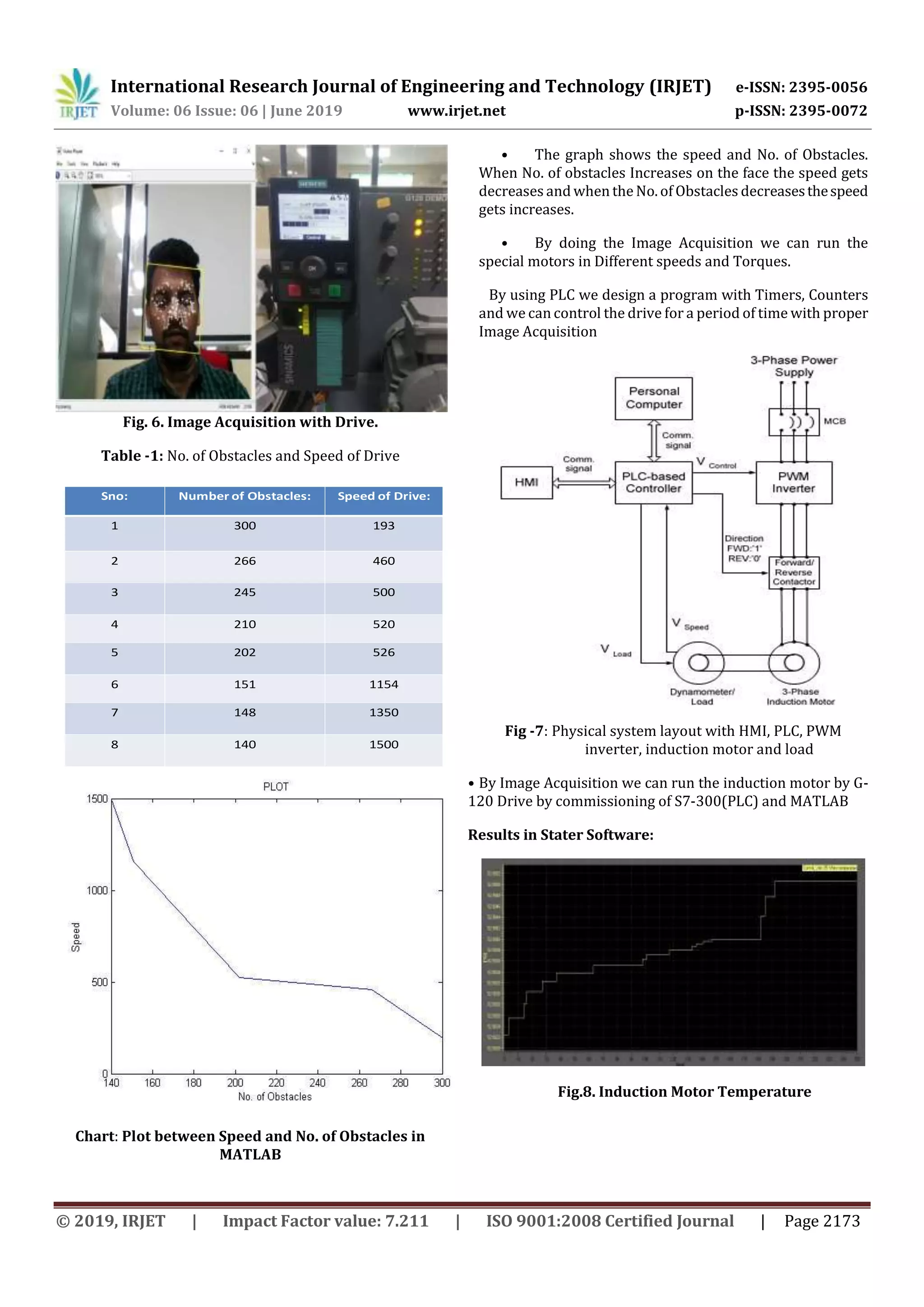
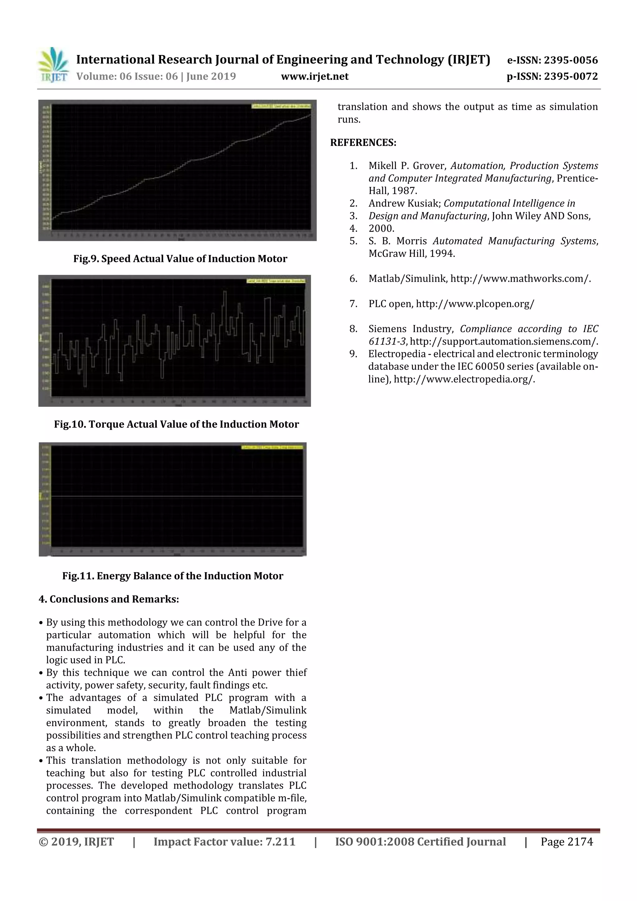

This document discusses modeling and controlling a variable frequency drive (VFD) system using a programmable logic controller (PLC) and MATLAB. A generic VFD-motor system model is proposed. The plant model is developed in MATLAB/Simulink. The aim is to simulate and analyze appropriate control techniques for real-time PLC implementation of variable speed drive control. A PLC-based controller controls motor speed in the presence of variable load through image acquisition. The PLC program is translated to MATLAB/Simulink for testing. Results show the induction motor's temperature, actual speed and torque values, and energy balance at different operating conditions when controlled by the PLC and drive.