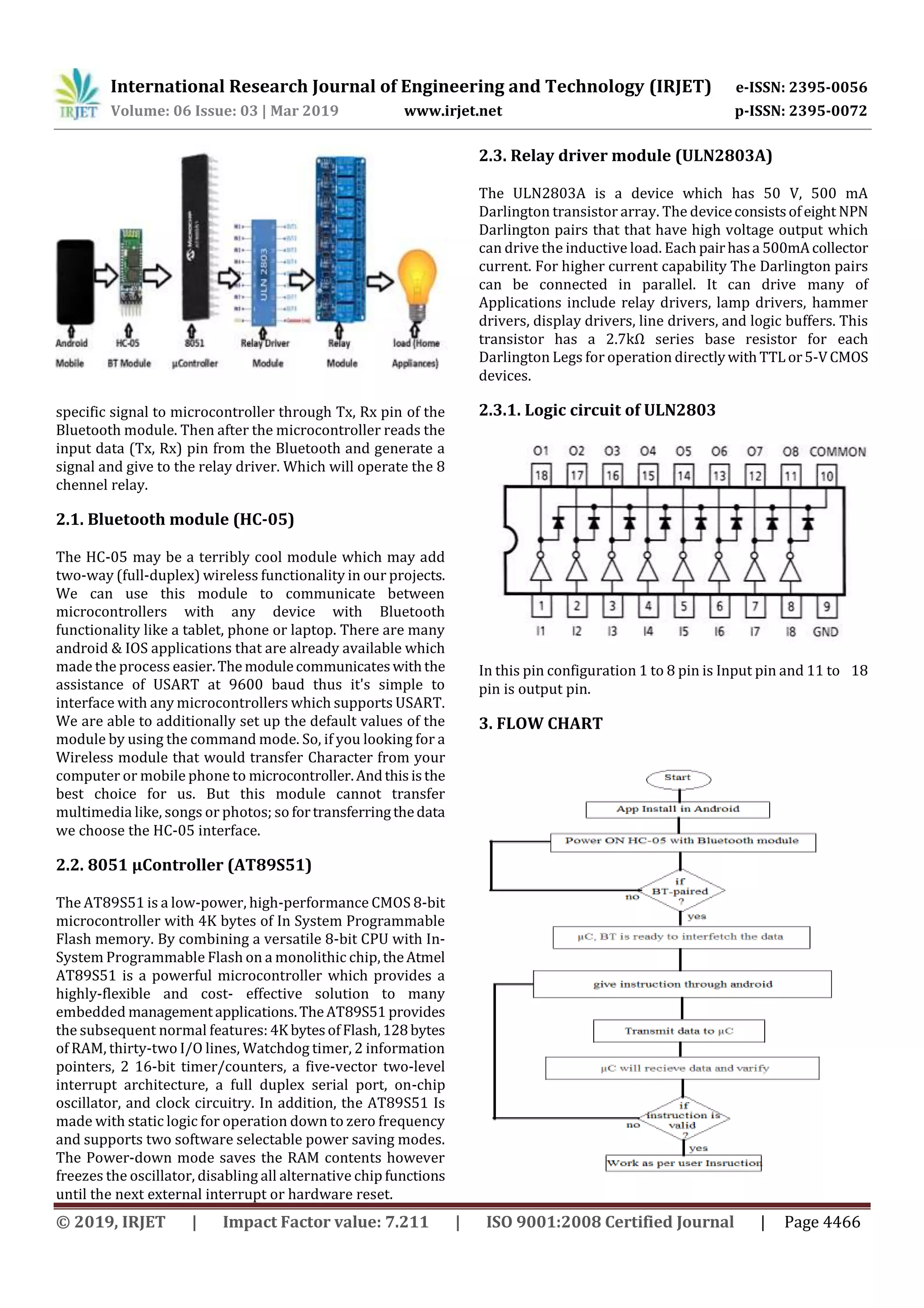
Download to read offline
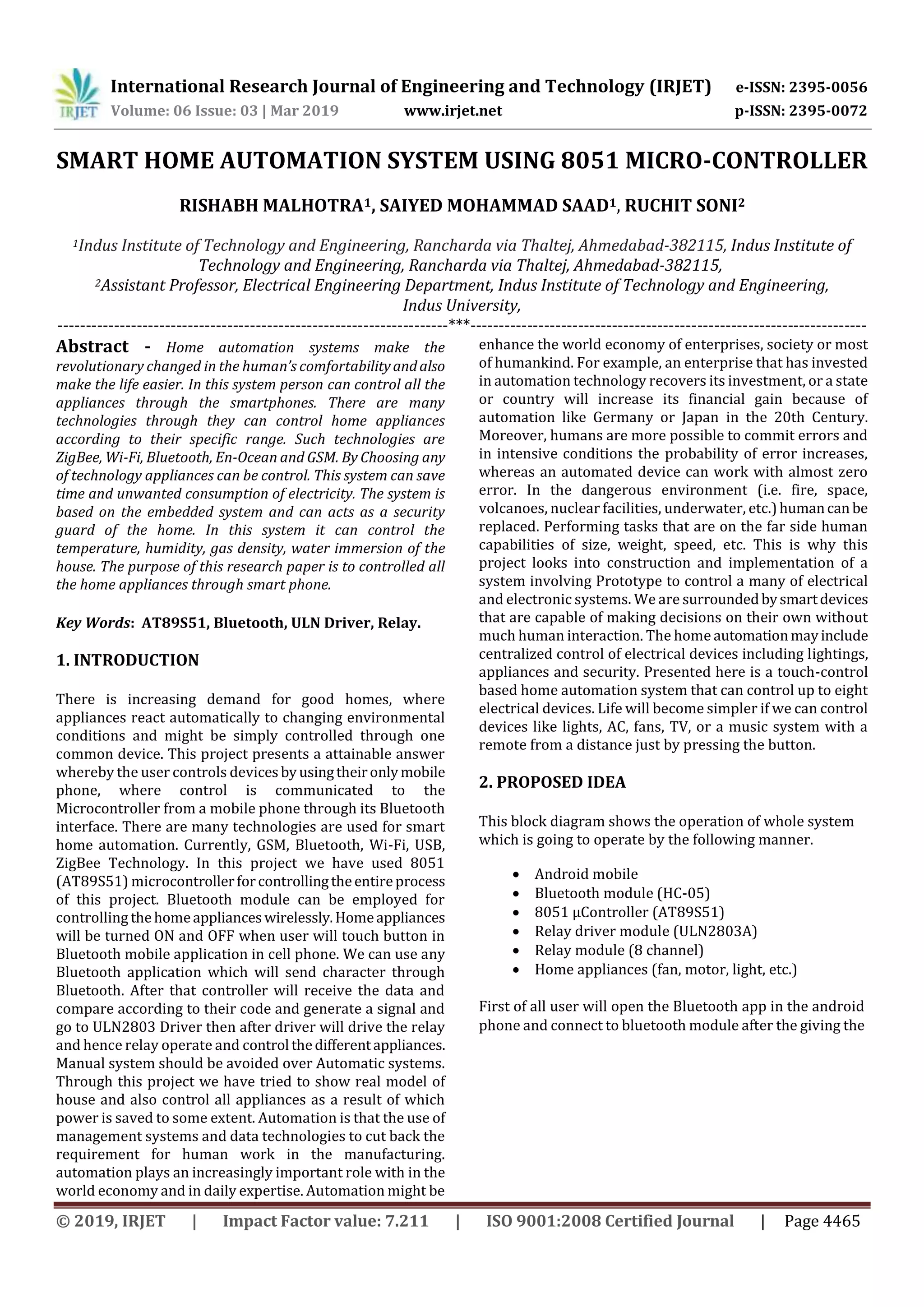


This document describes a smart home automation system that allows users to control home appliances remotely using a smartphone. The system uses an 8051 microcontroller connected to a Bluetooth module to receive control signals from a mobile app. When the user presses buttons in the app, characters are transmitted via Bluetooth to the microcontroller. It decodes the signals and activates relays connected to home appliances like lights and fans, turning them on and off. The system is designed to automate home appliances and save energy by remote control using Bluetooth communication between a smartphone and microcontroller.