The document provides a comprehensive overview of the 8051 microcontroller, including its internal architecture, comparison to microprocessors, and various applications in home, office, and automotive systems. It covers the features, memory structure, instruction set, and addressing modes, along with guidance for selecting an appropriate microcontroller based on specific criteria. Additionally, it delves into programming aspects and examples of operations in assembly language for the 8051.
![Special Function Registers [SFR] 8051 Microcontroller 26](https://image.slidesharecdn.com/unit1-240621044110-2cd739b1/75/INTRODUCTION-TO-MICROCONTROLLERS-8051-ARCHITECTURE-INSTRUCTION-SET-ADDRESSING-MODES-26-2048.jpg)
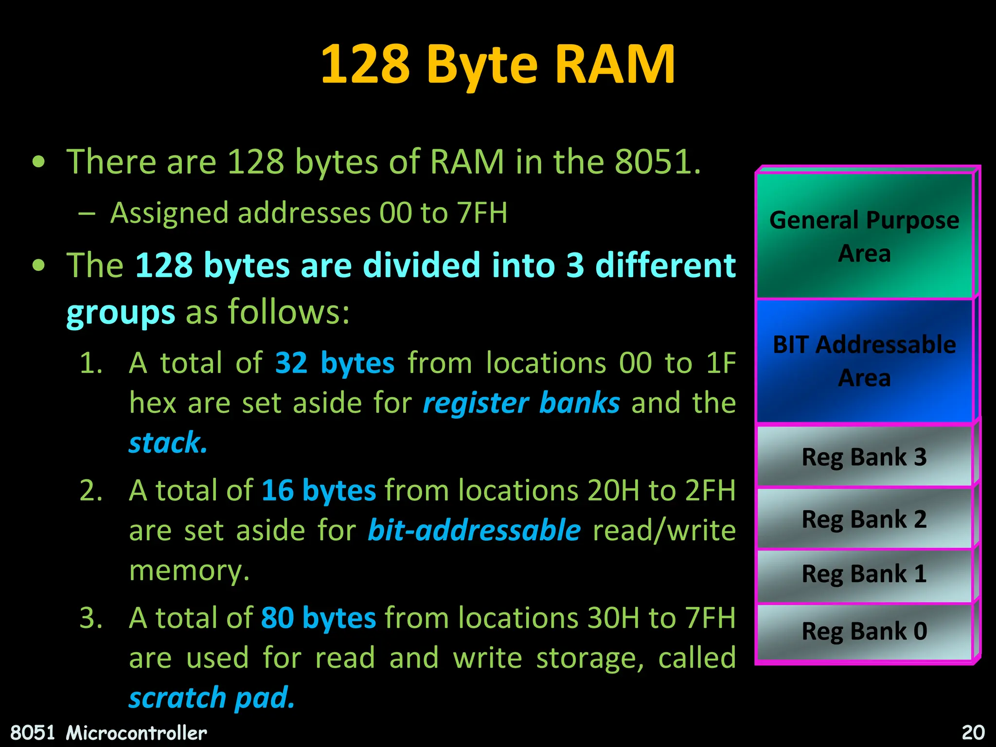
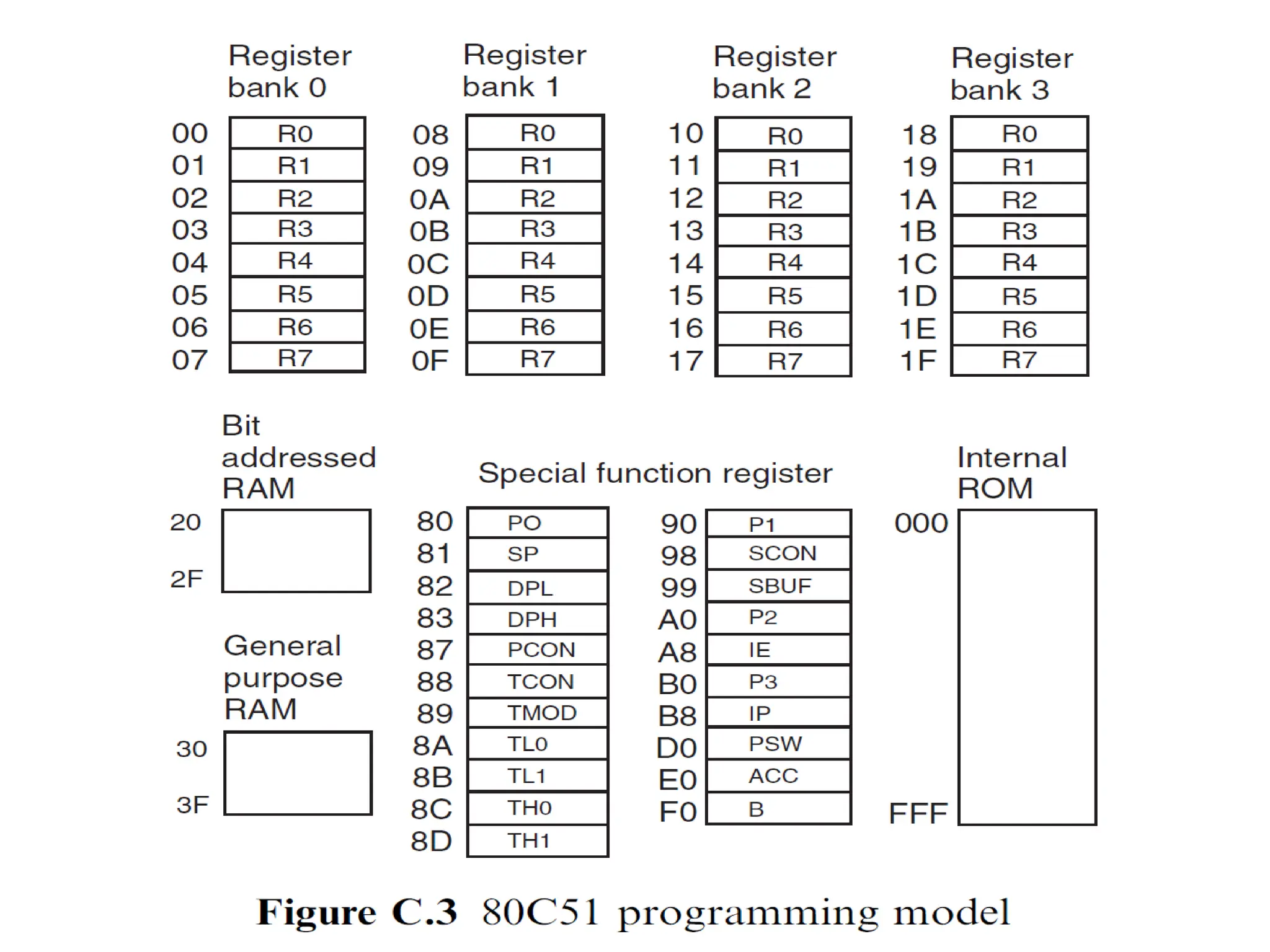
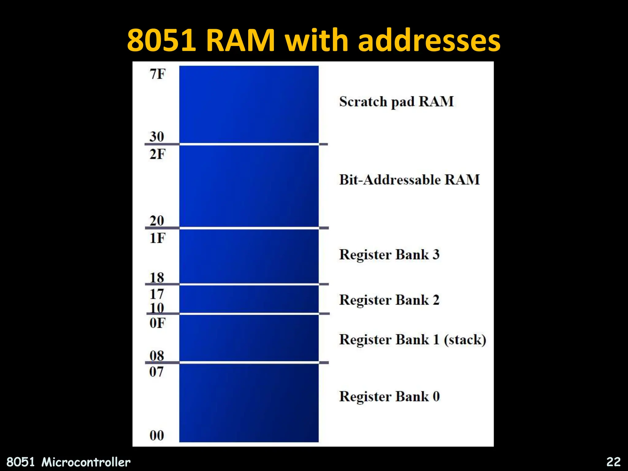
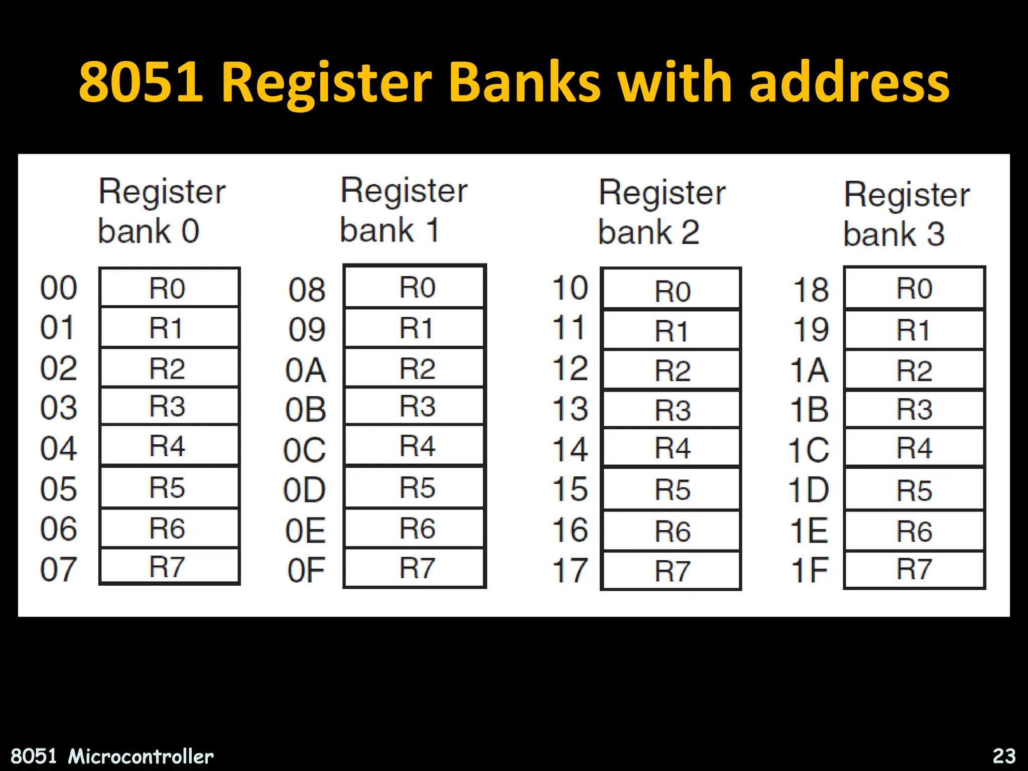
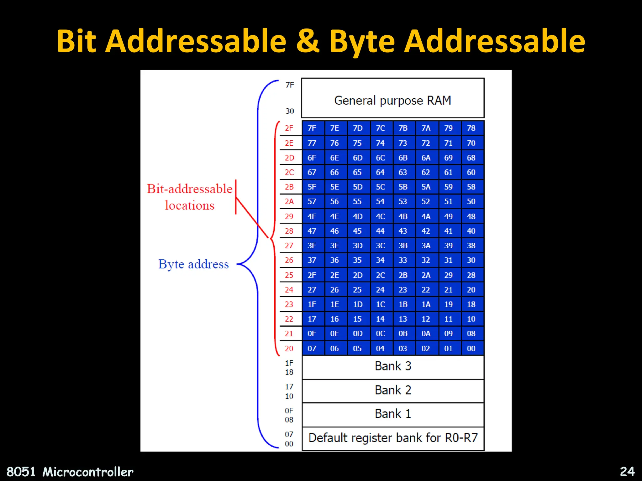
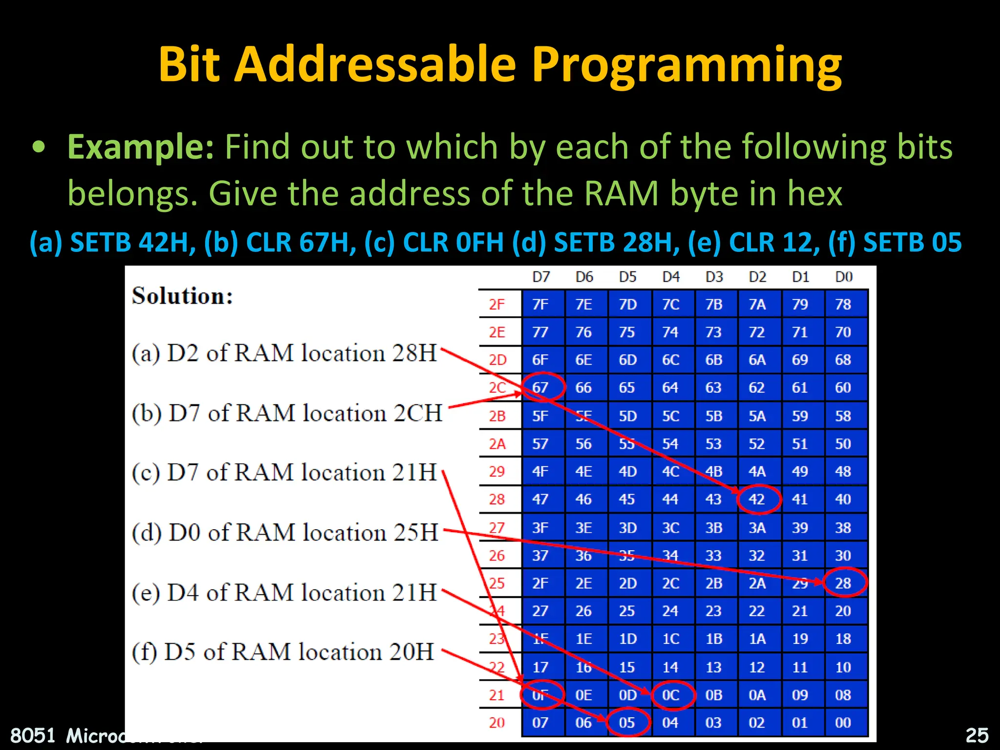
![Internal RAM Structure Direct & Indirect Addressing Direct Addressing Only SFR [ Special Function Registers] 128 Byte Internal RAM 8051 Microcontroller 27](https://image.slidesharecdn.com/unit1-240621044110-2cd739b1/75/INTRODUCTION-TO-MICROCONTROLLERS-8051-ARCHITECTURE-INSTRUCTION-SET-ADDRESSING-MODES-27-2048.jpg)
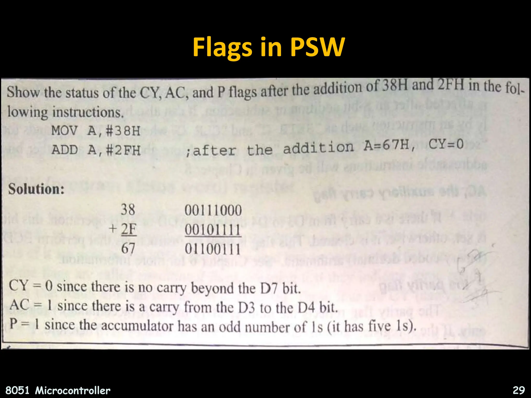
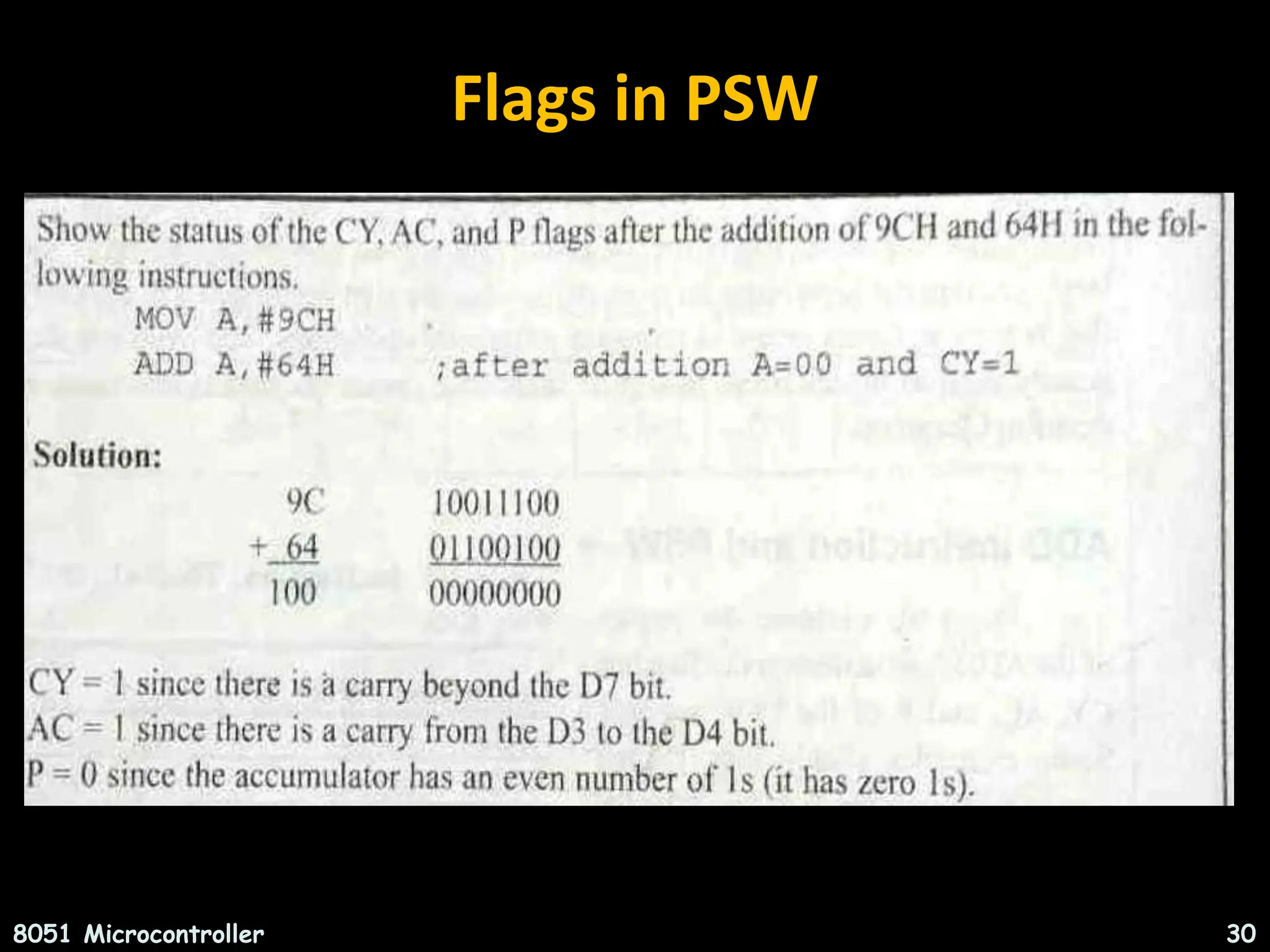
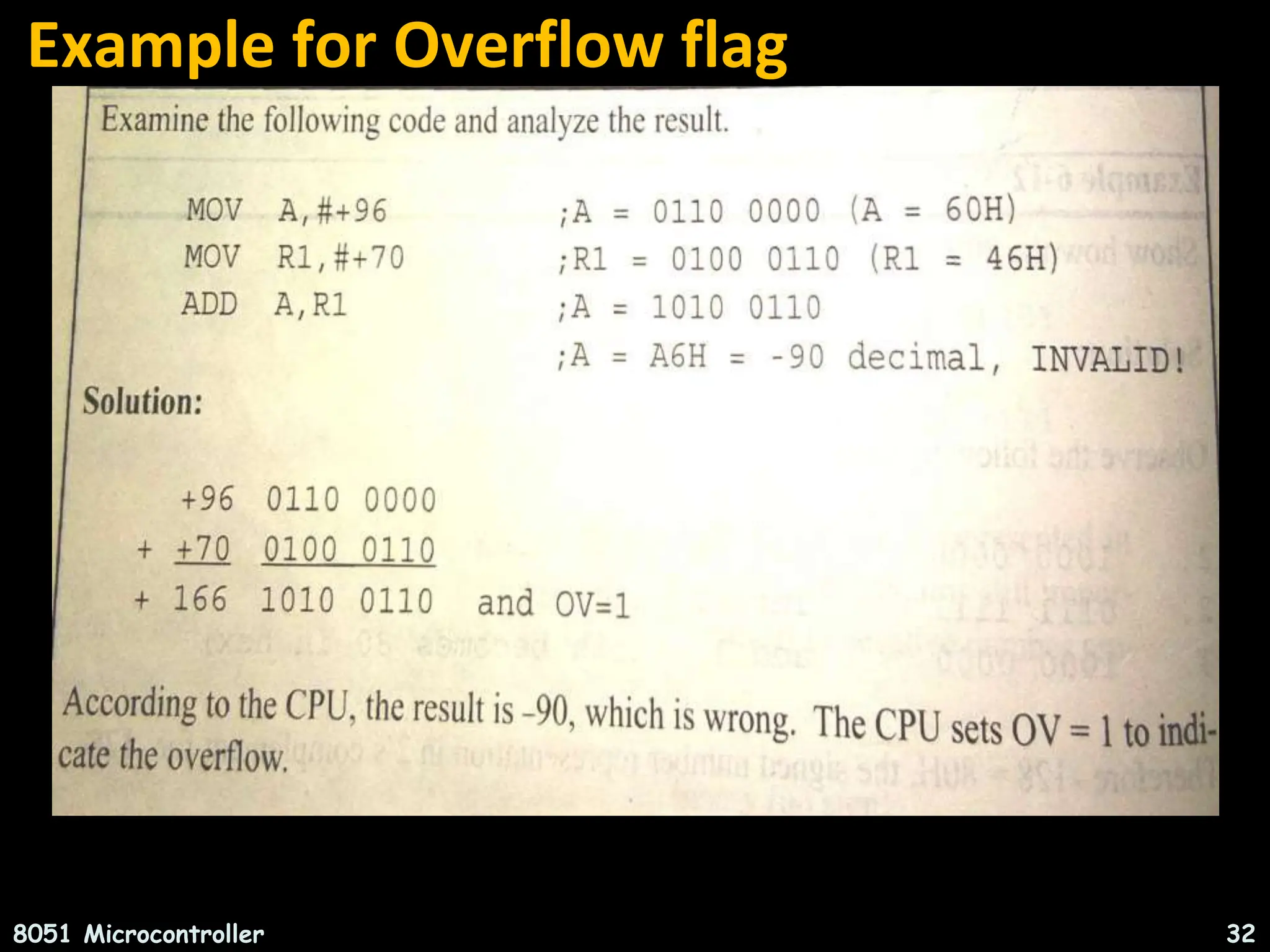
![Program Status Word [PSW] 8051 Microcontroller 28 C AC F0 RS1 RS0 OV -- P Register Bank Select Carry Auxiliary Carry User Flag 0 Parity Reserved for future use Overflow](https://image.slidesharecdn.com/unit1-240621044110-2cd739b1/75/INTRODUCTION-TO-MICROCONTROLLERS-8051-ARCHITECTURE-INSTRUCTION-SET-ADDRESSING-MODES-28-2048.jpg)


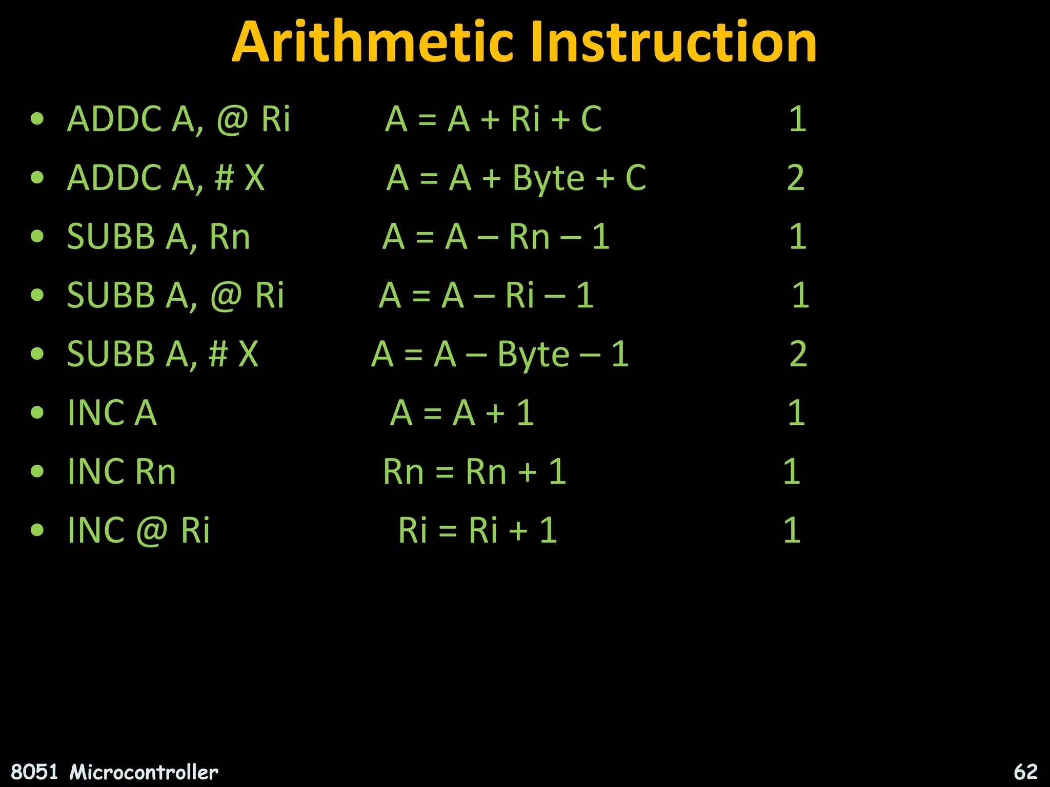
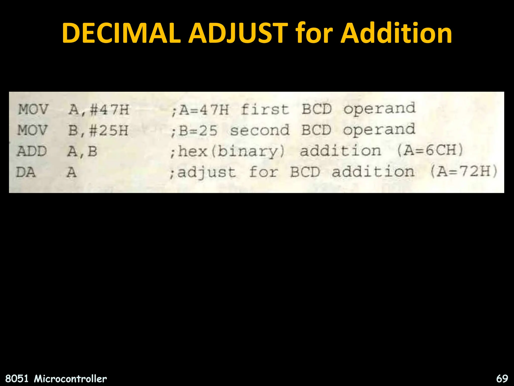
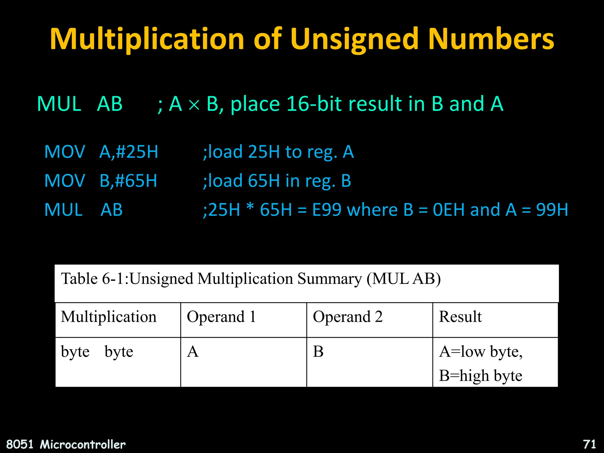
![Arithmetic Instruction • DEC A A = A – 1 1 • DEC Rn Rn = Rn – 1 1 • DEC @ Ri Ri = Ri – 1 1 • INC DPTR DPTR = DPTR + 1 1 • MUL AB B:A = A * B 1 • DIV AB A = [A/B] 1 • DA A Decimal adjustment of 1 accumulator according to BCD code 8051 Microcontroller 63](https://image.slidesharecdn.com/unit1-240621044110-2cd739b1/75/INTRODUCTION-TO-MICROCONTROLLERS-8051-ARCHITECTURE-INSTRUCTION-SET-ADDRESSING-MODES-63-2048.jpg)