
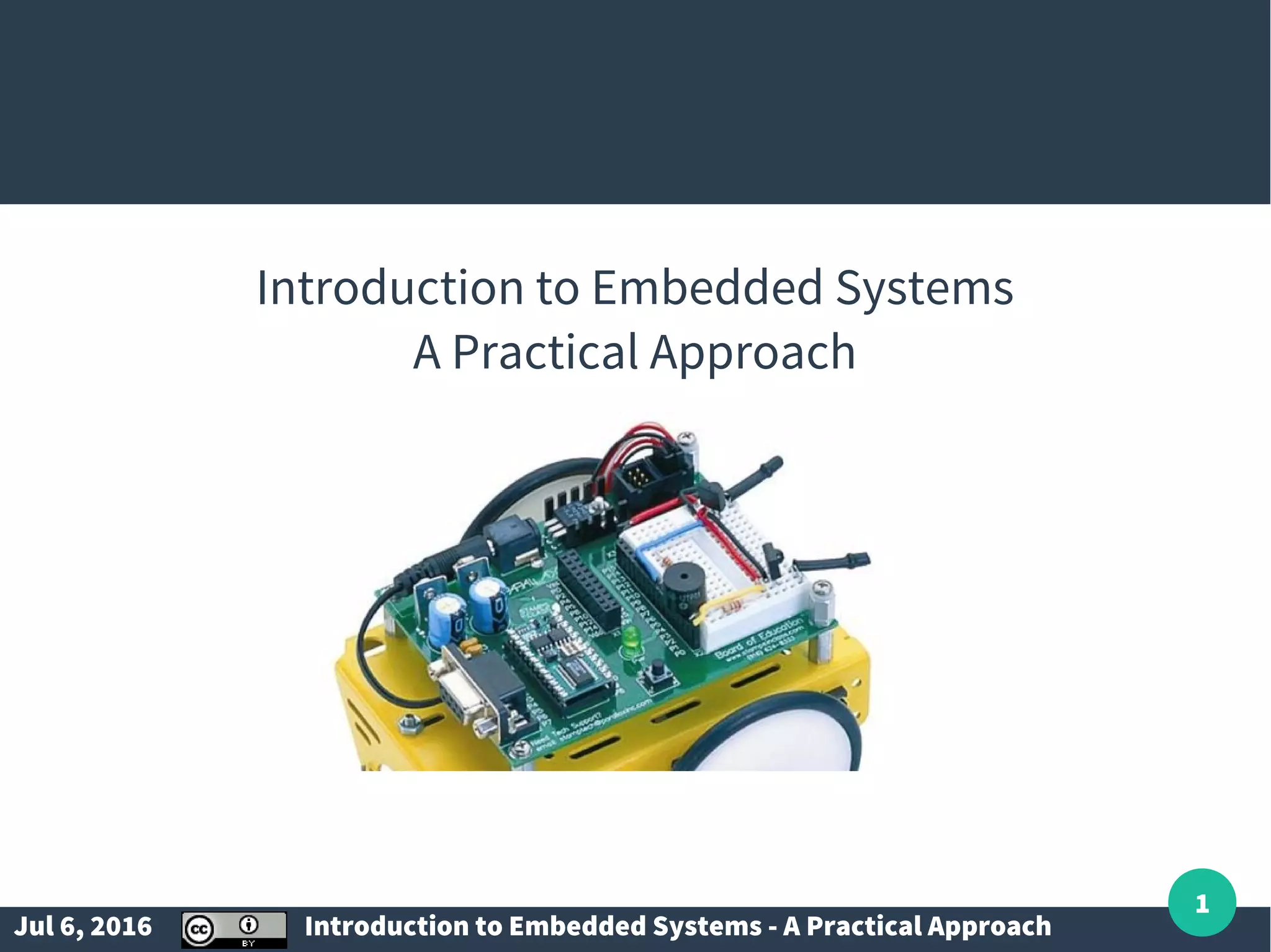


The document serves as an introduction to embedded systems, focusing on understanding microcontrollers and designing software for them. It outlines prerequisites, objectives, and a comprehensive course structure, covering topics such as programming in C, interfacing, real-time constraints, and case studies. Additionally, it discusses the PIC16F887 microcontroller, memory types, interrupts, and various embedded system design concepts.
Overview and objectives of the presentation on Embedded Systems; importance of µ-Controllers.
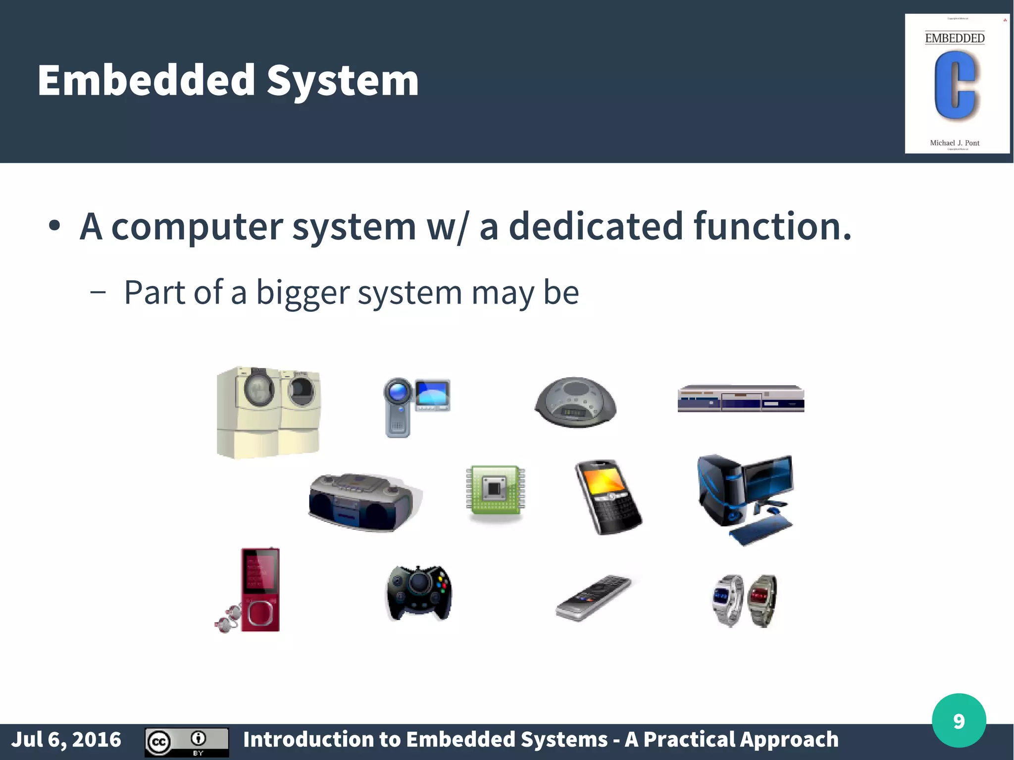
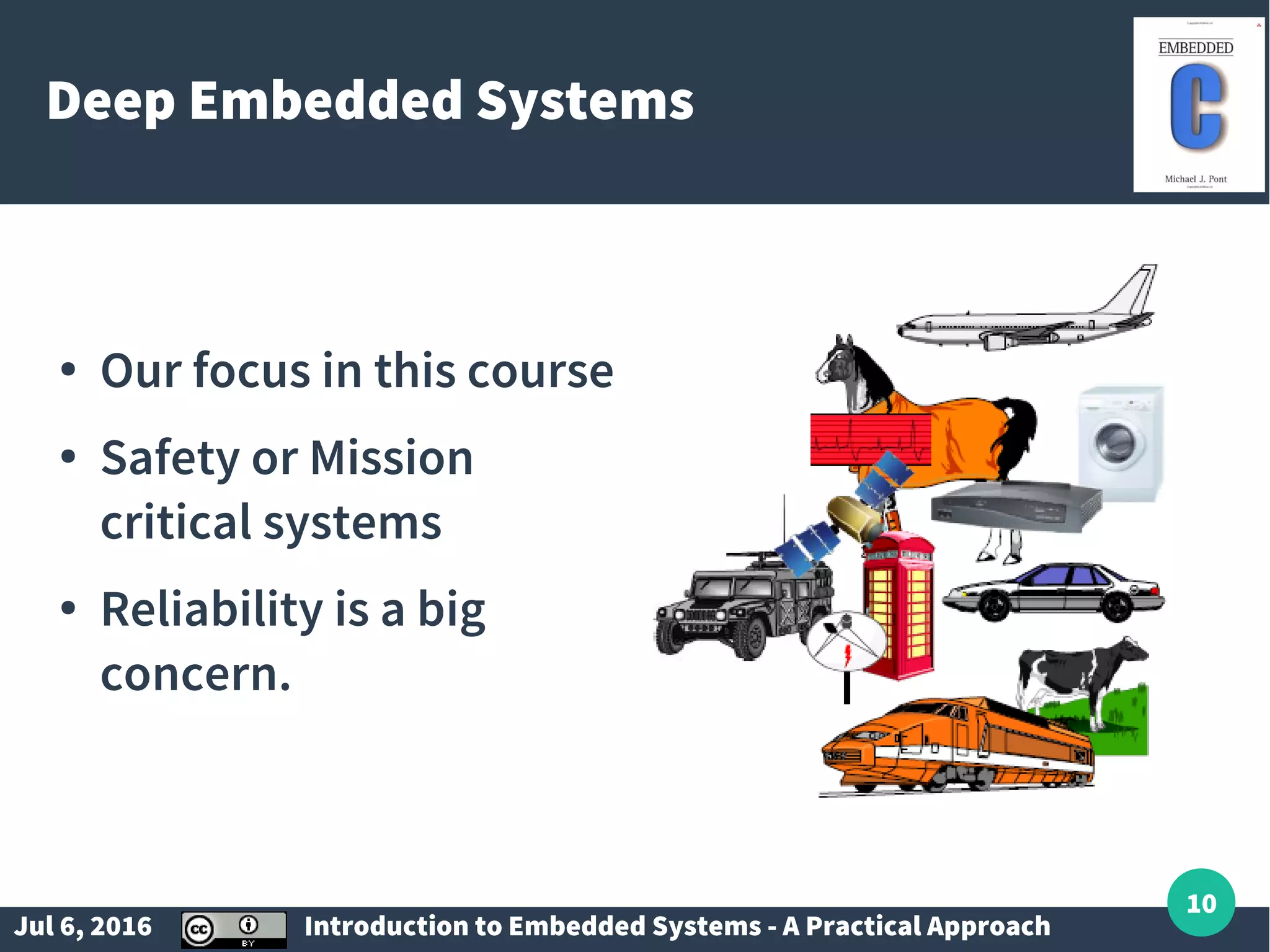
Definition and features of embedded systems; focusing on deep embedded systems critical for safety and reliability.
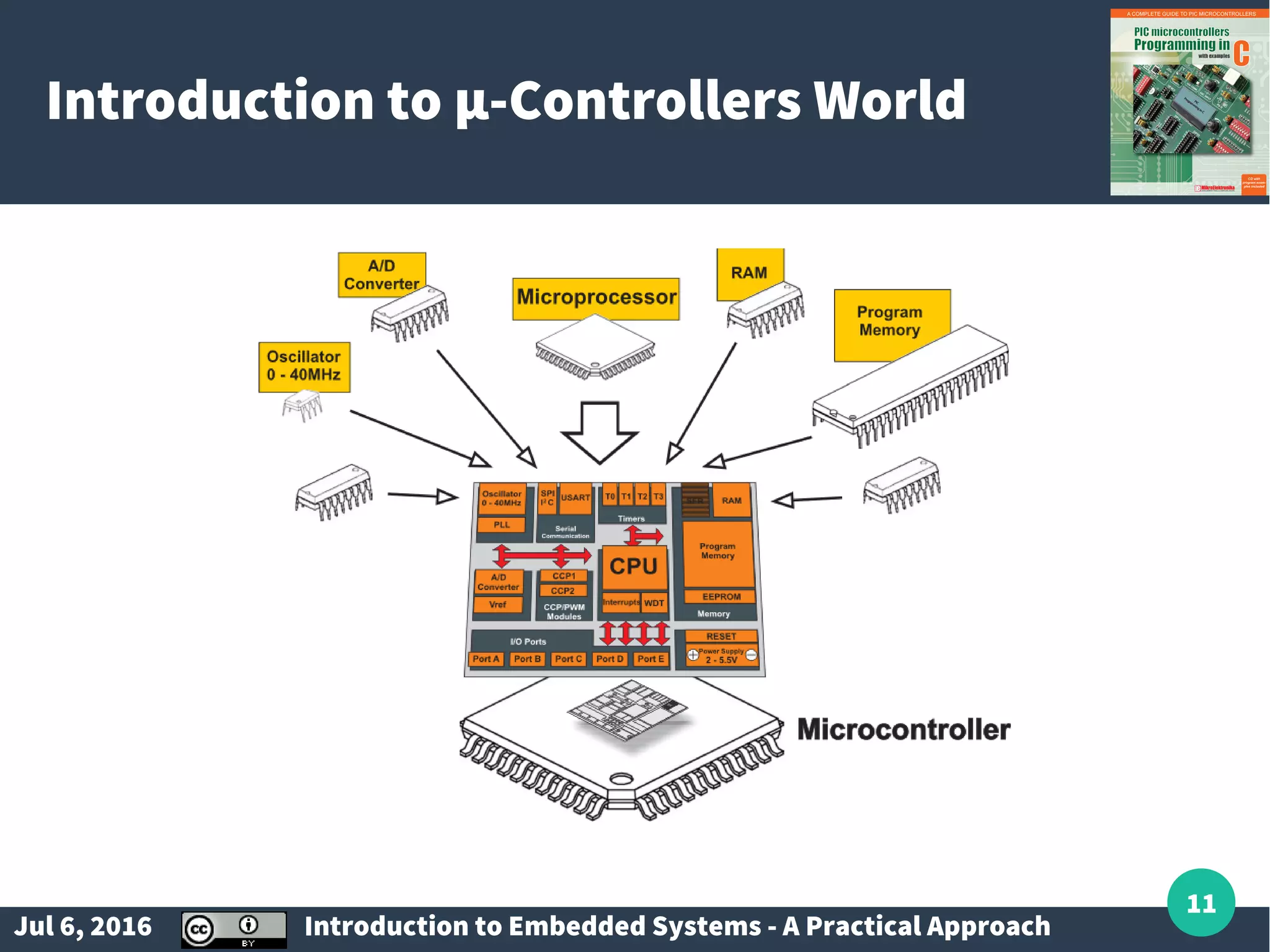
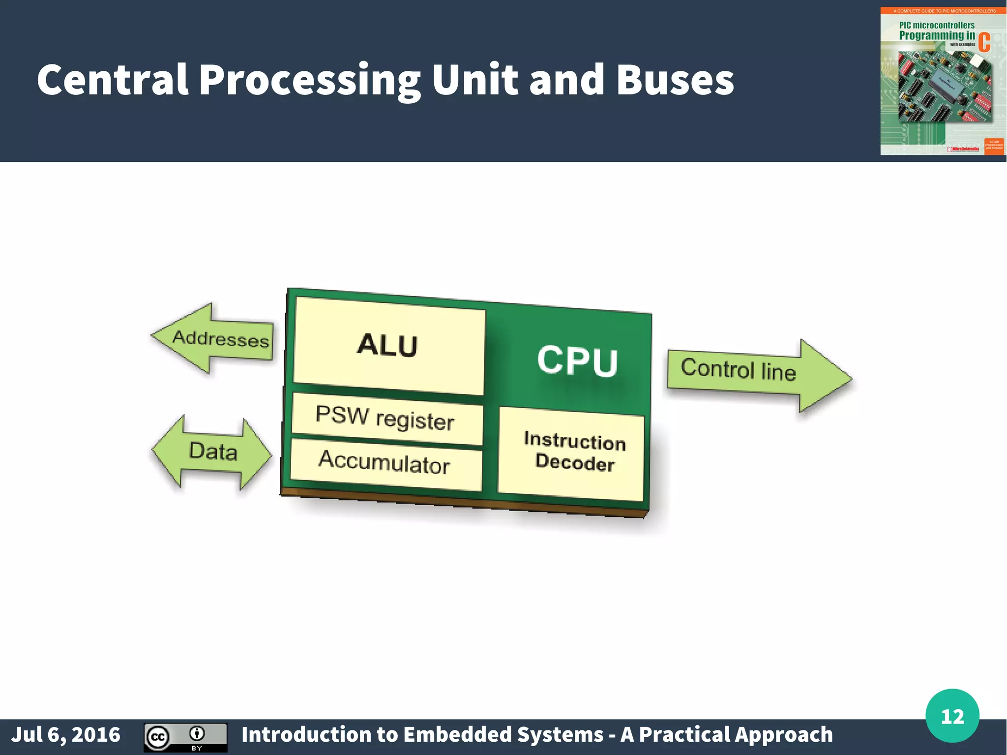
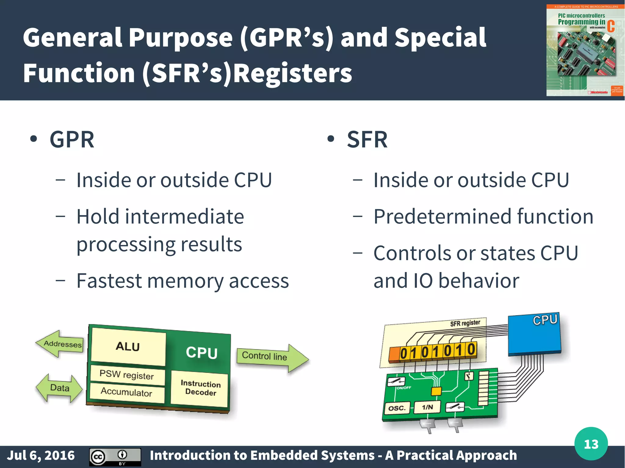
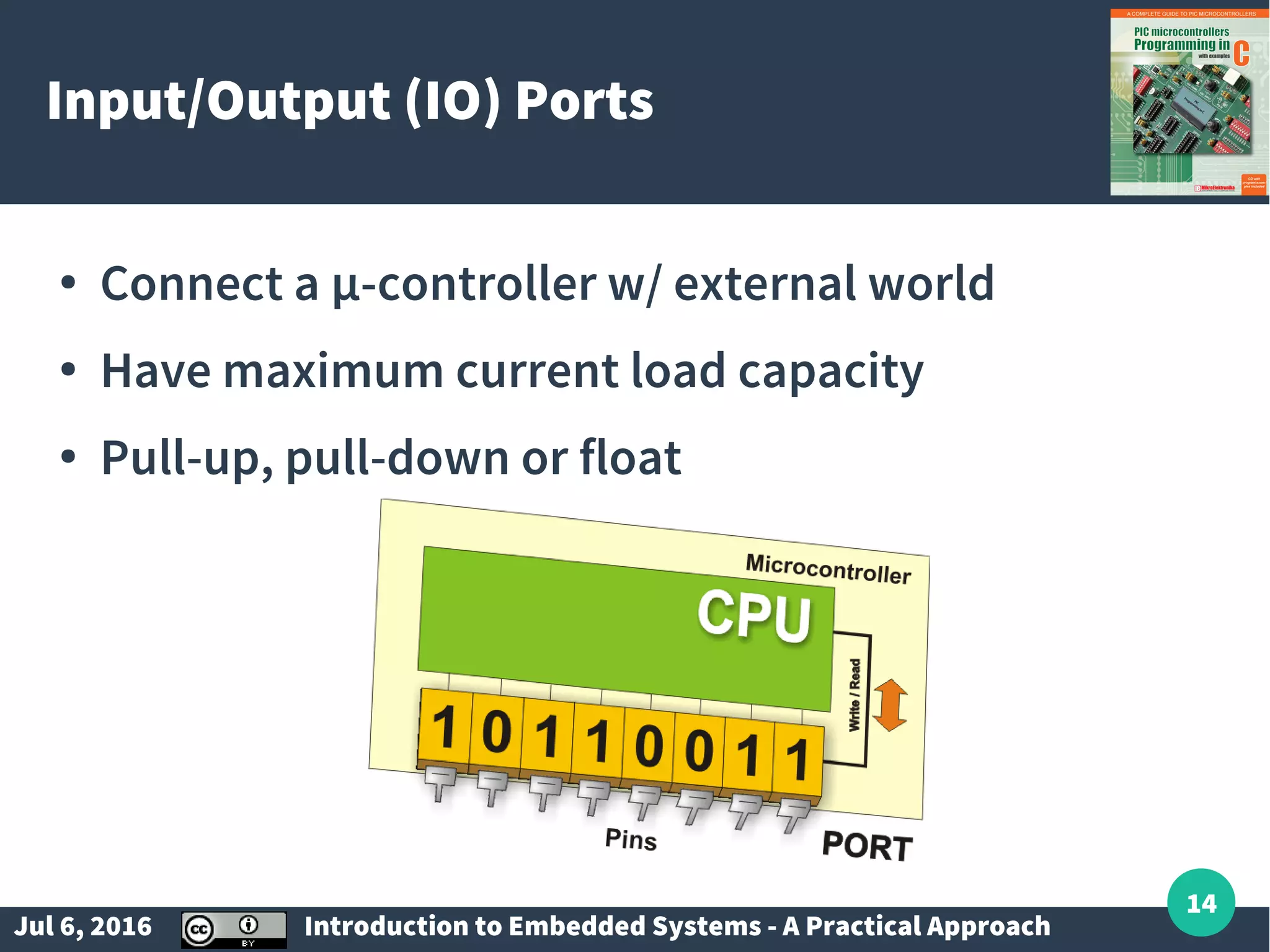
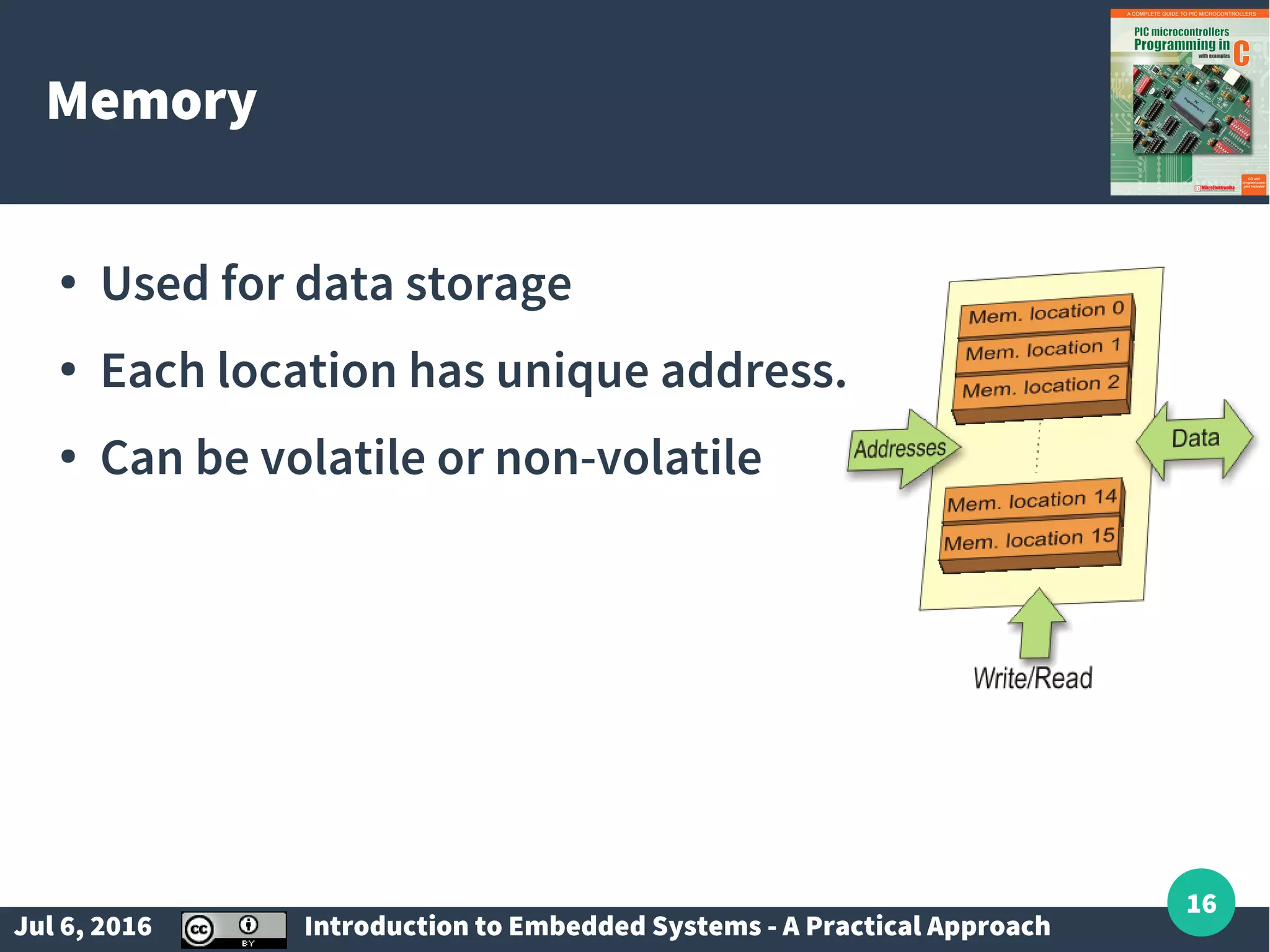
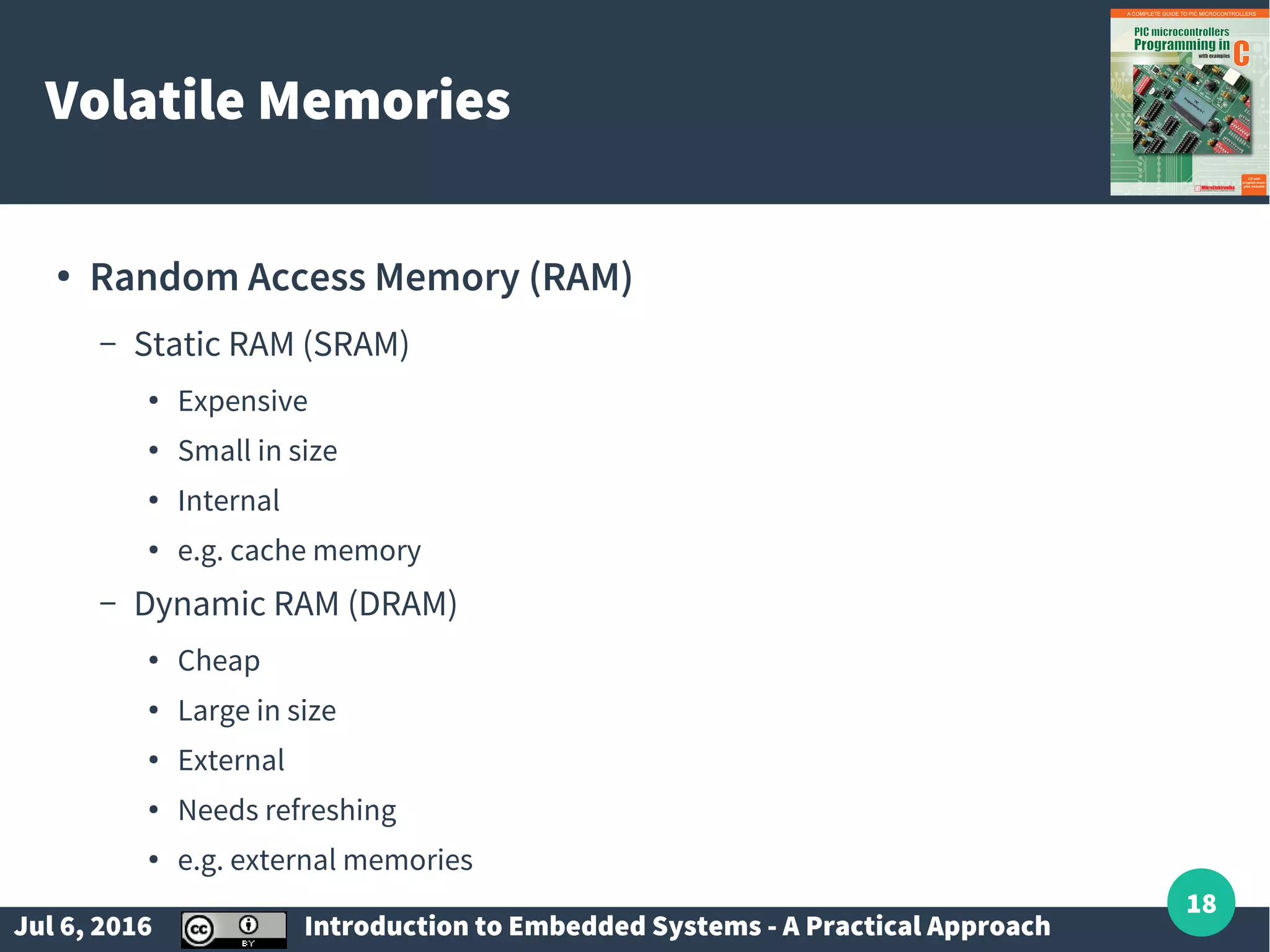
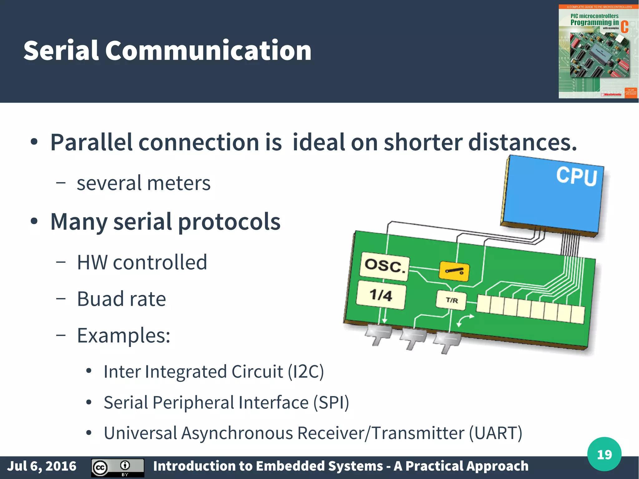
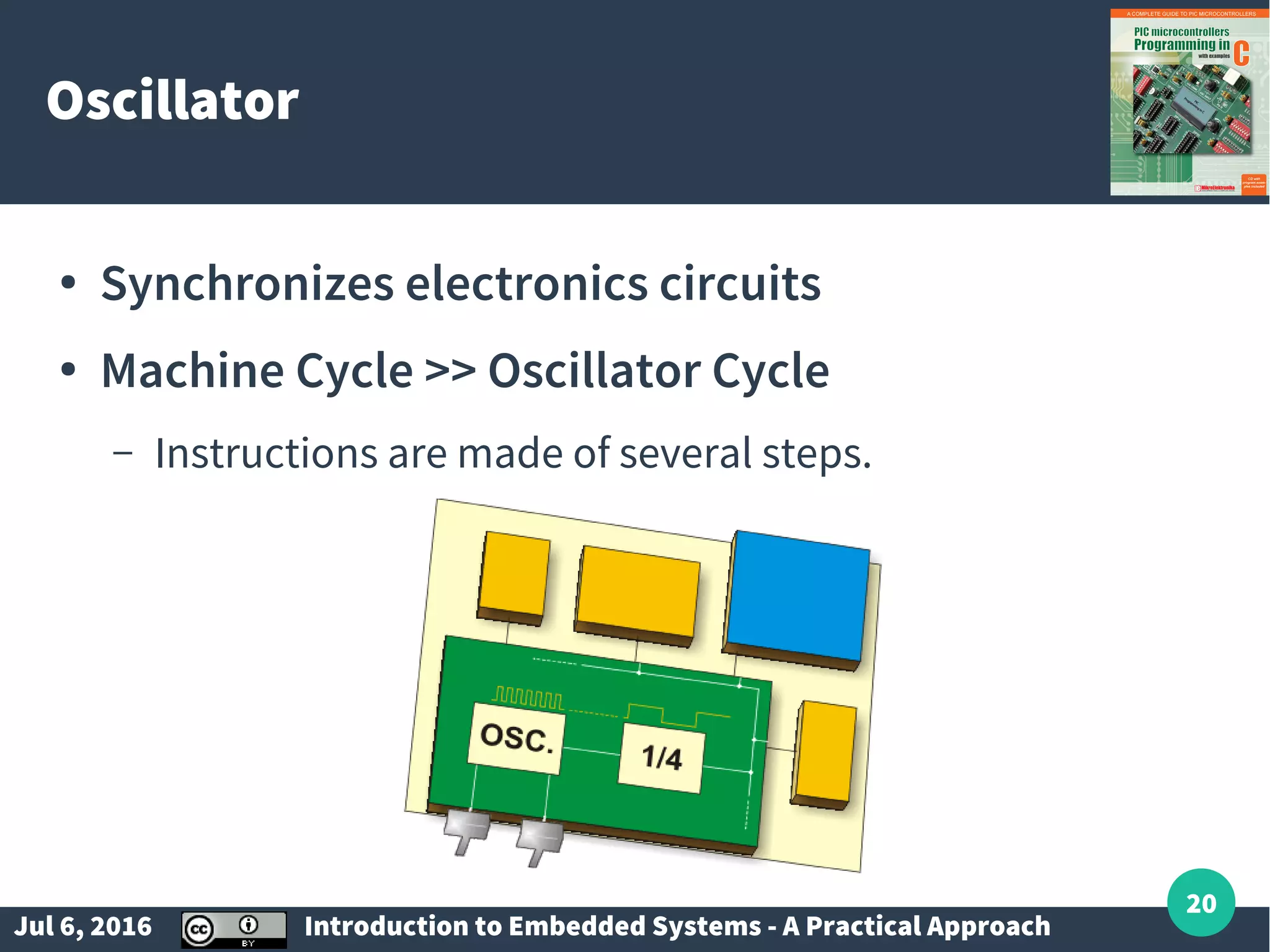
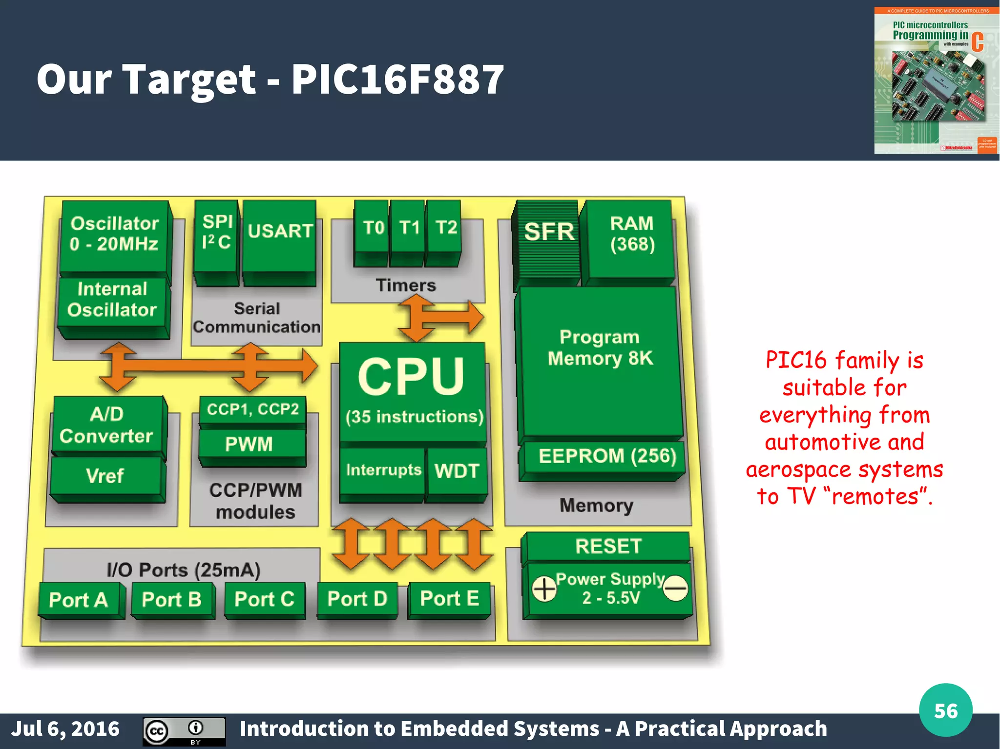
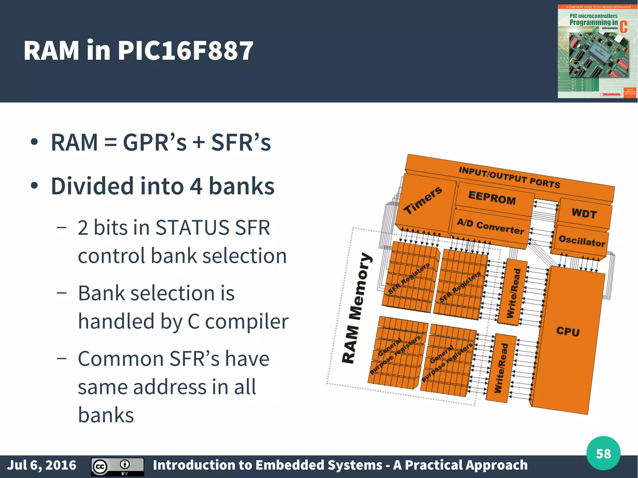
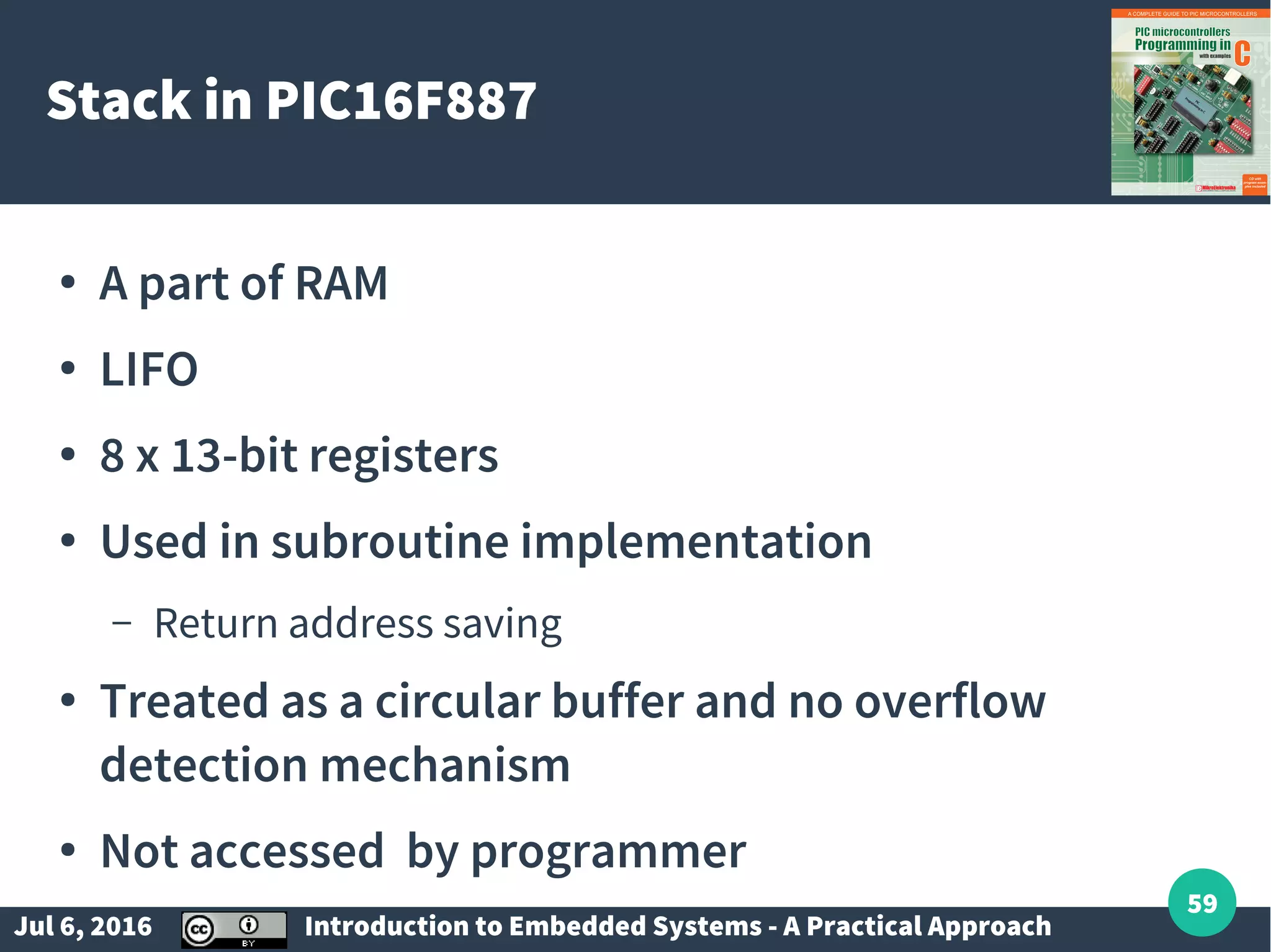
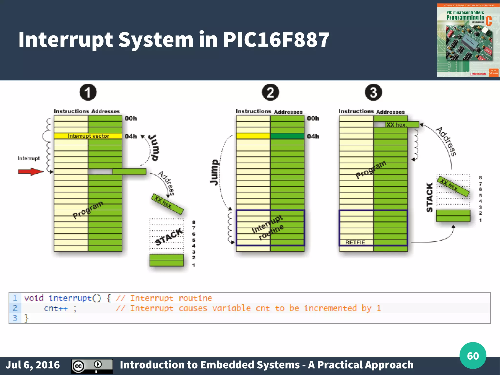
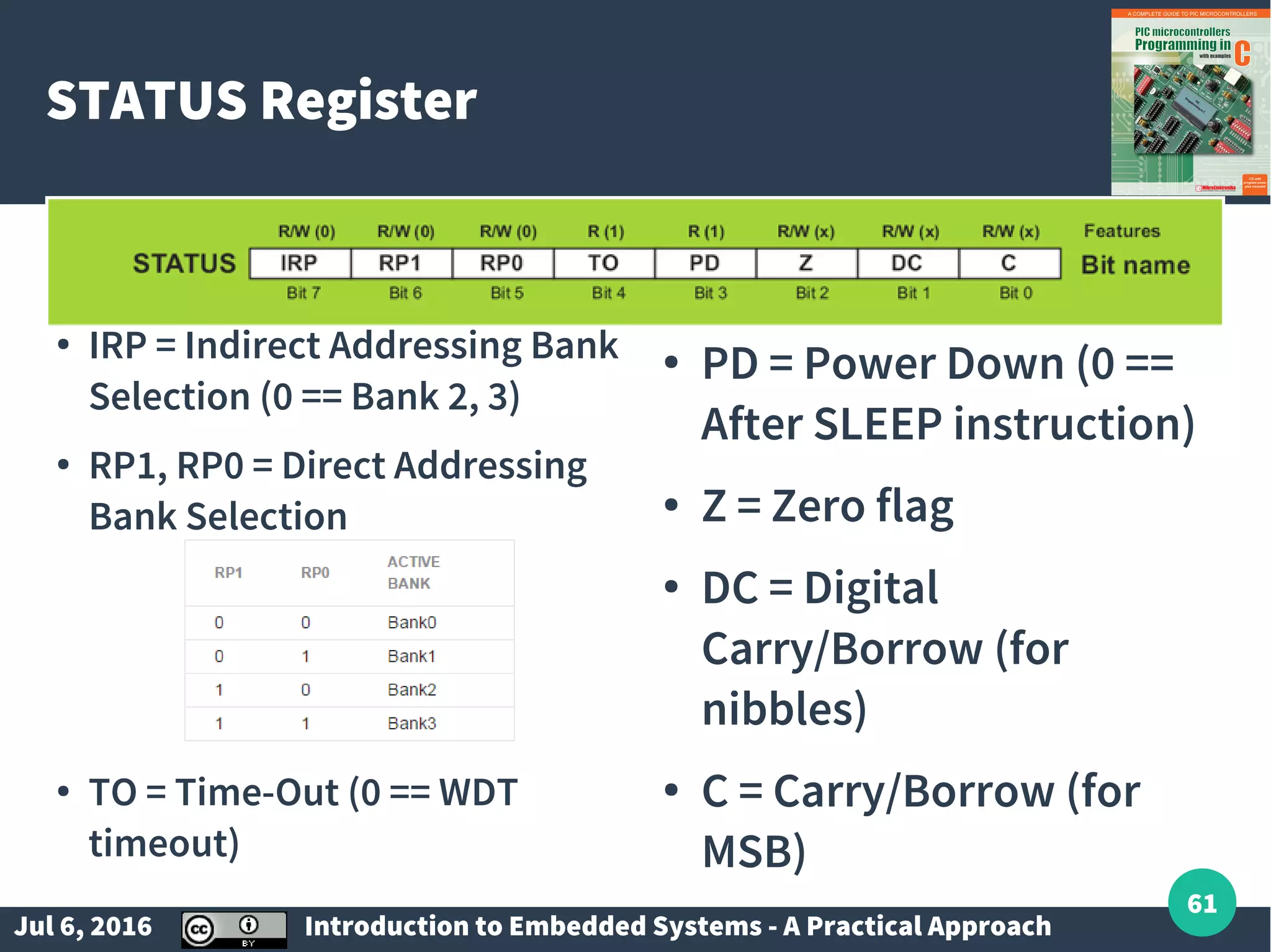
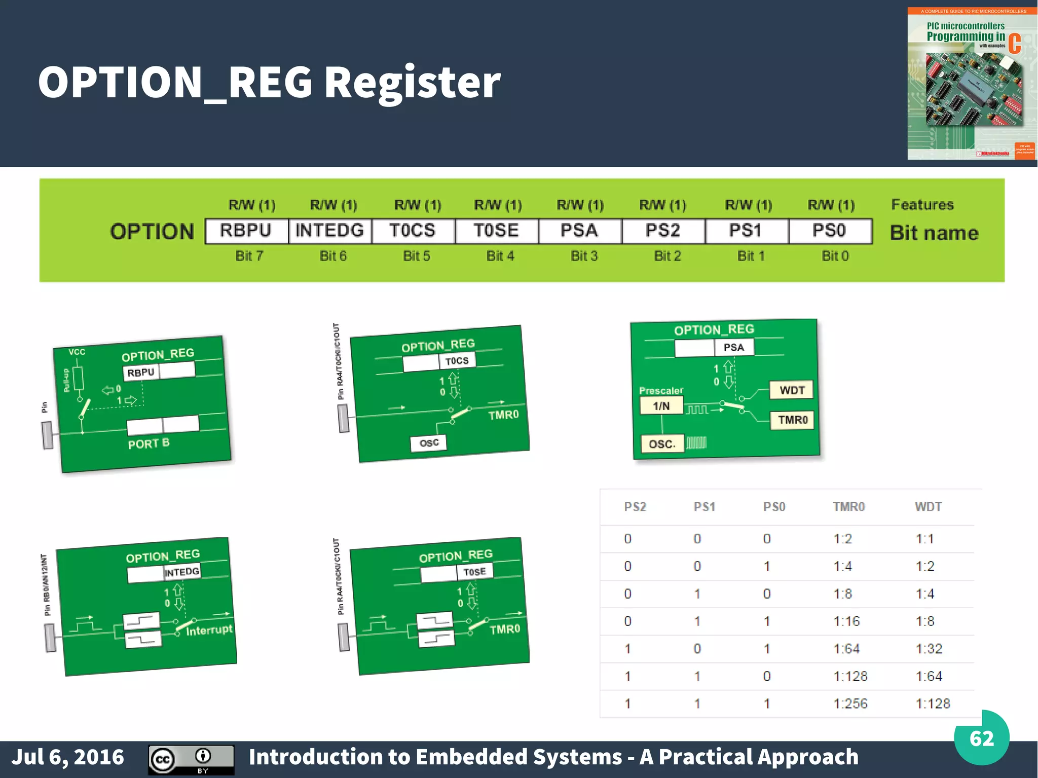
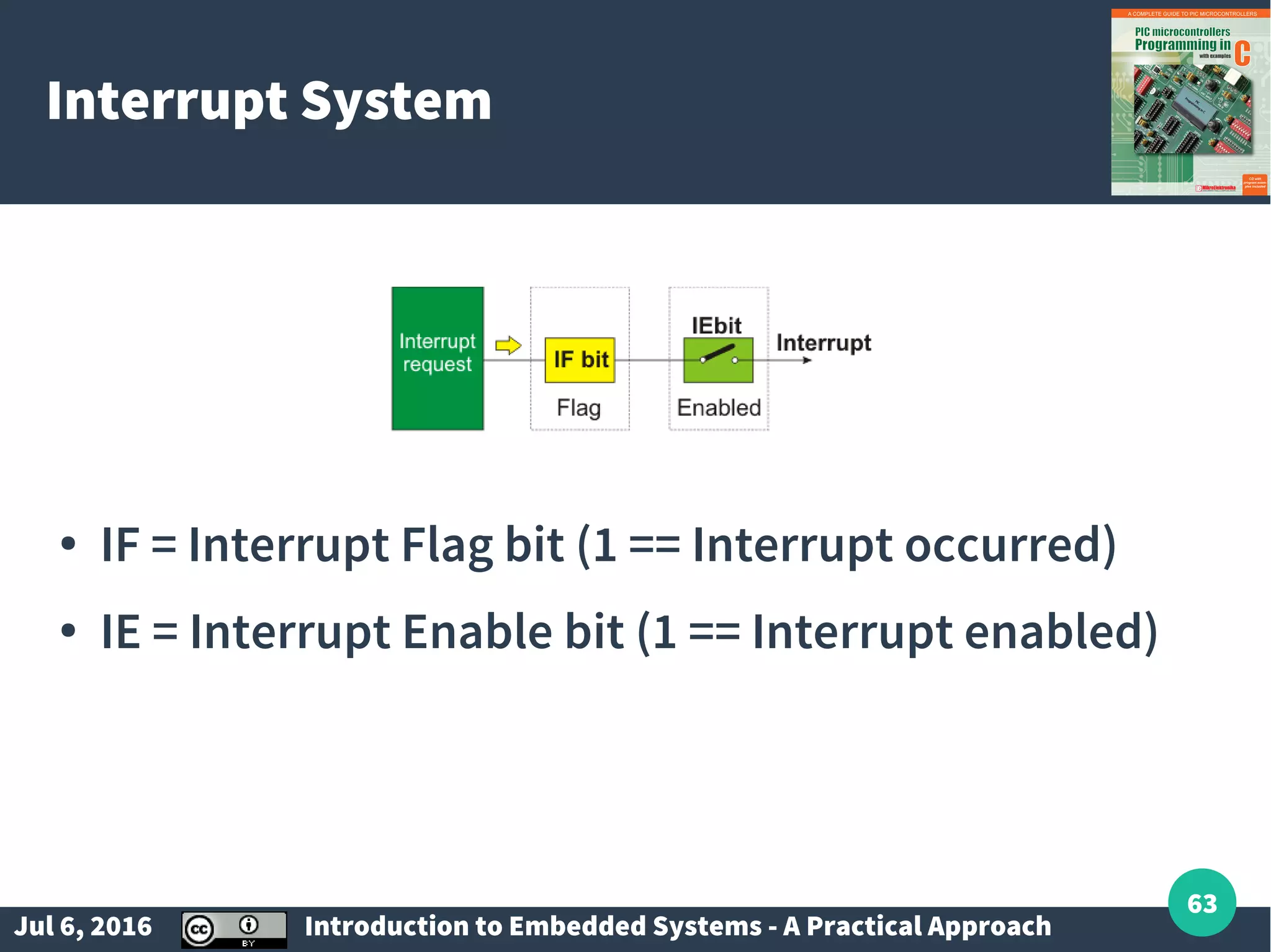
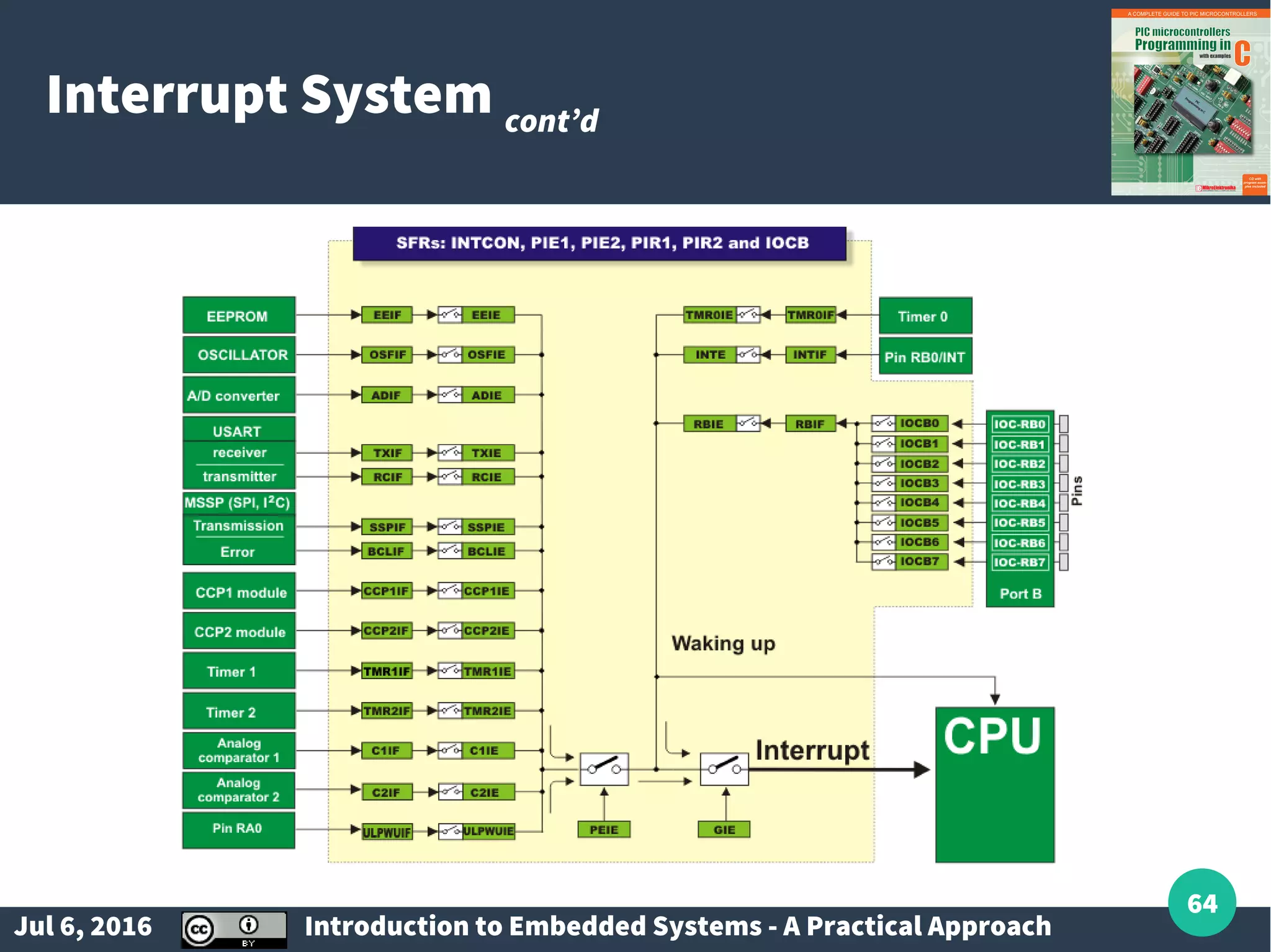
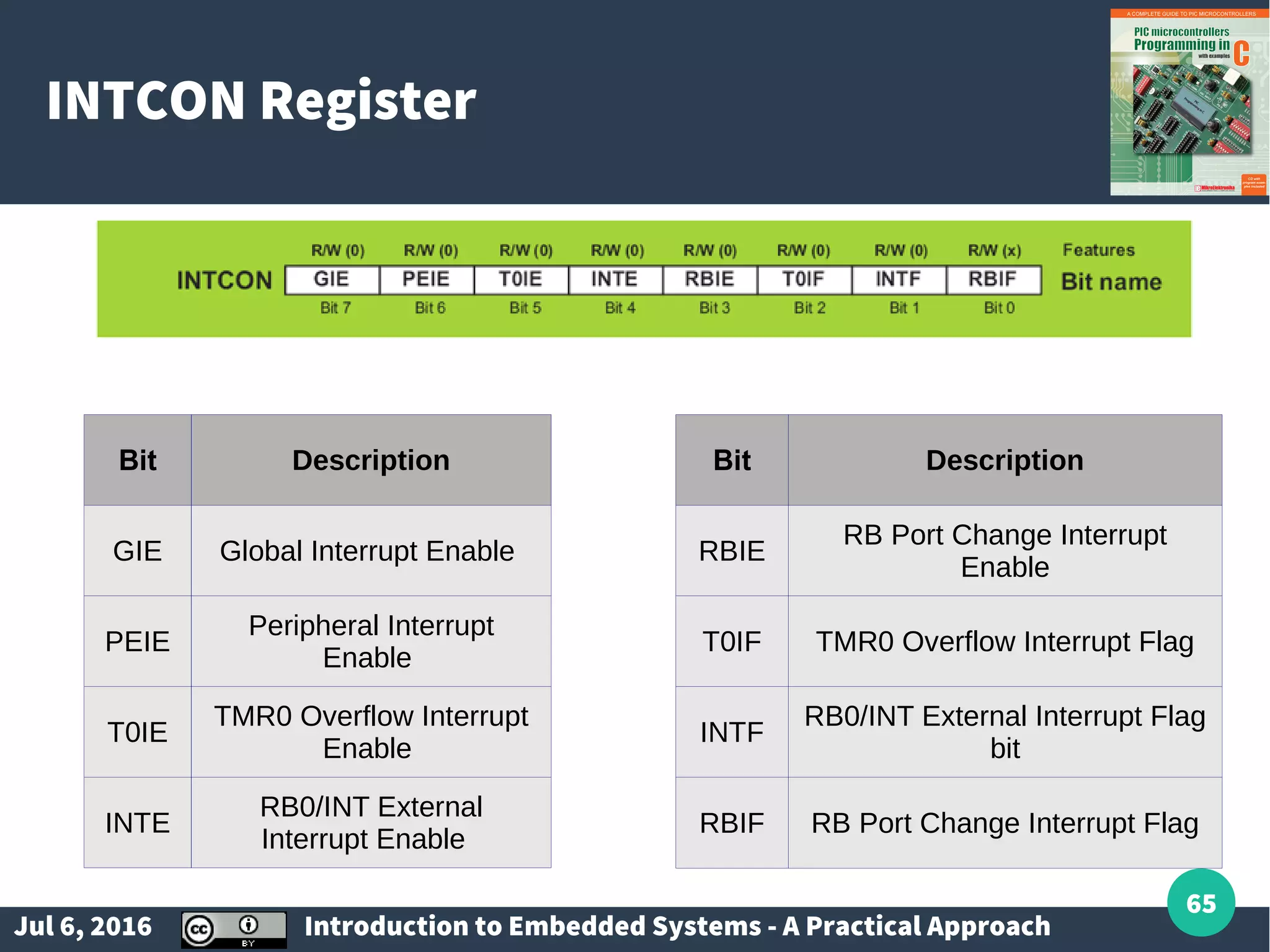
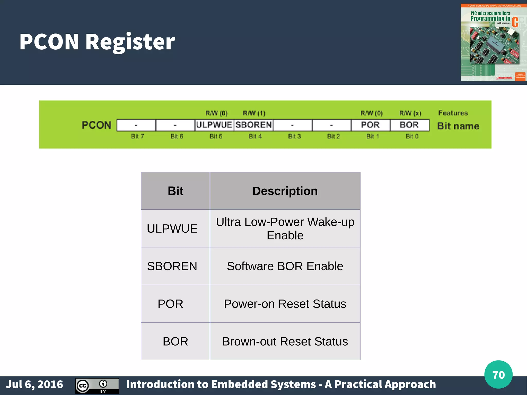
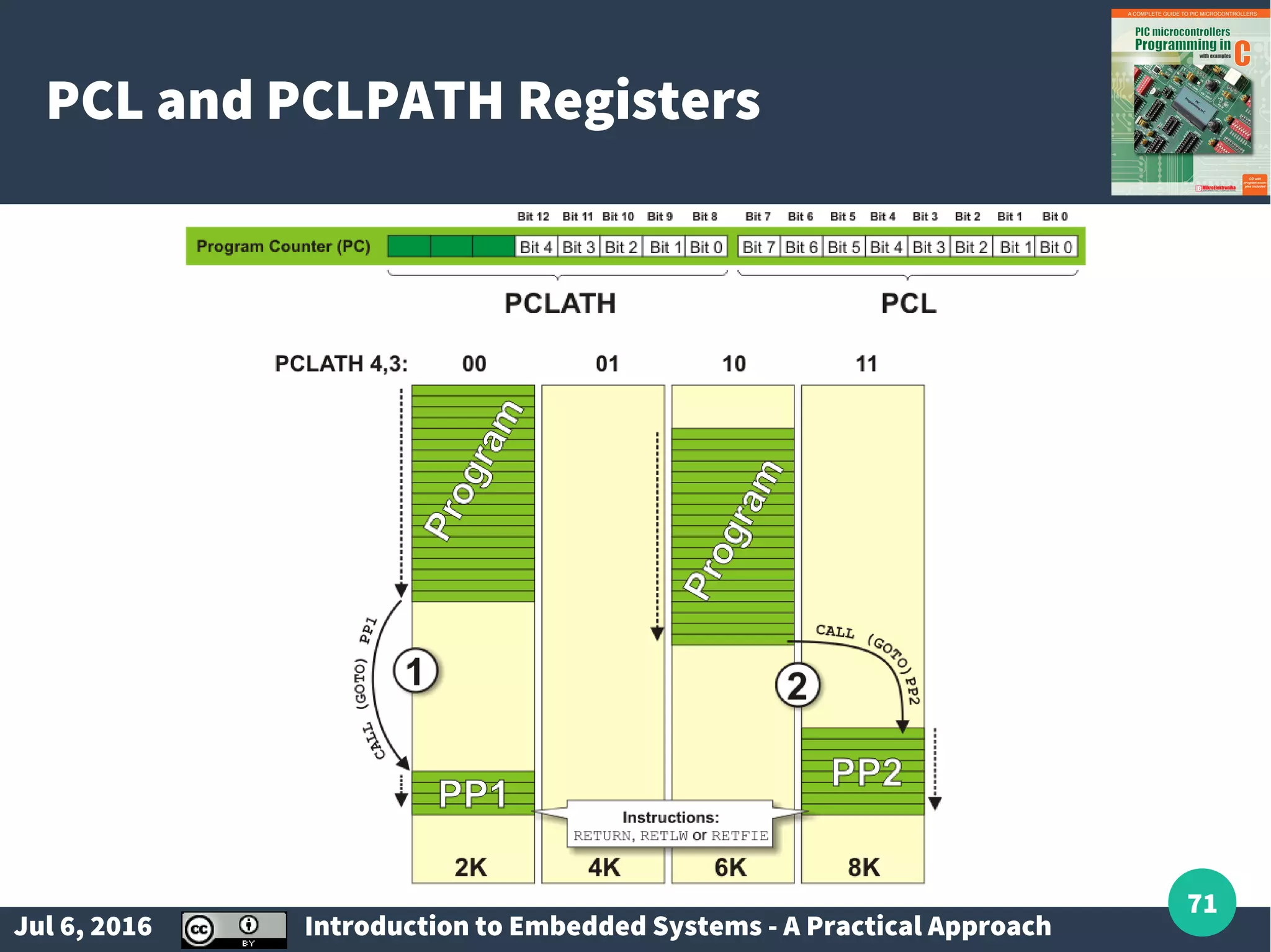
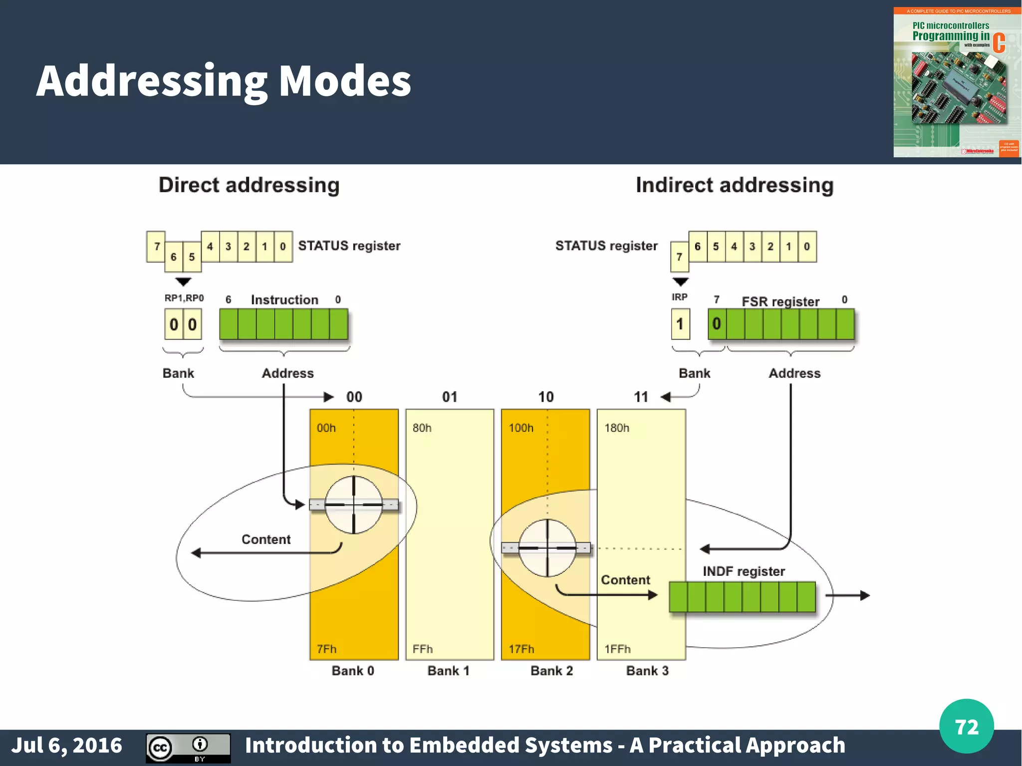
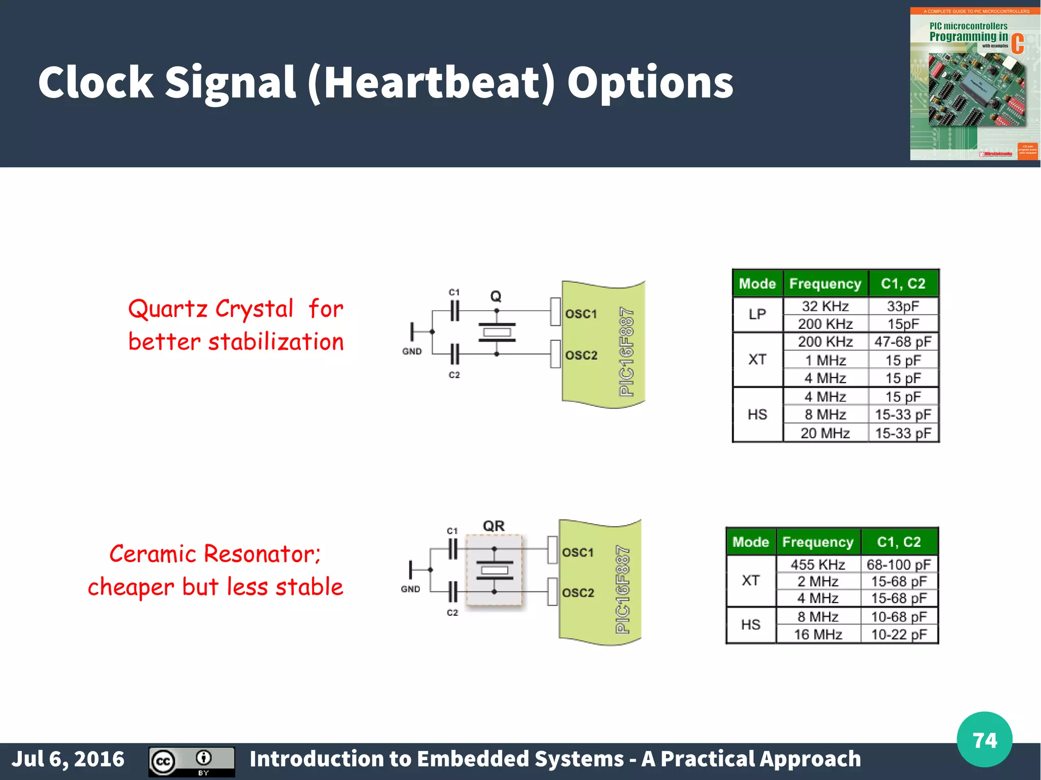
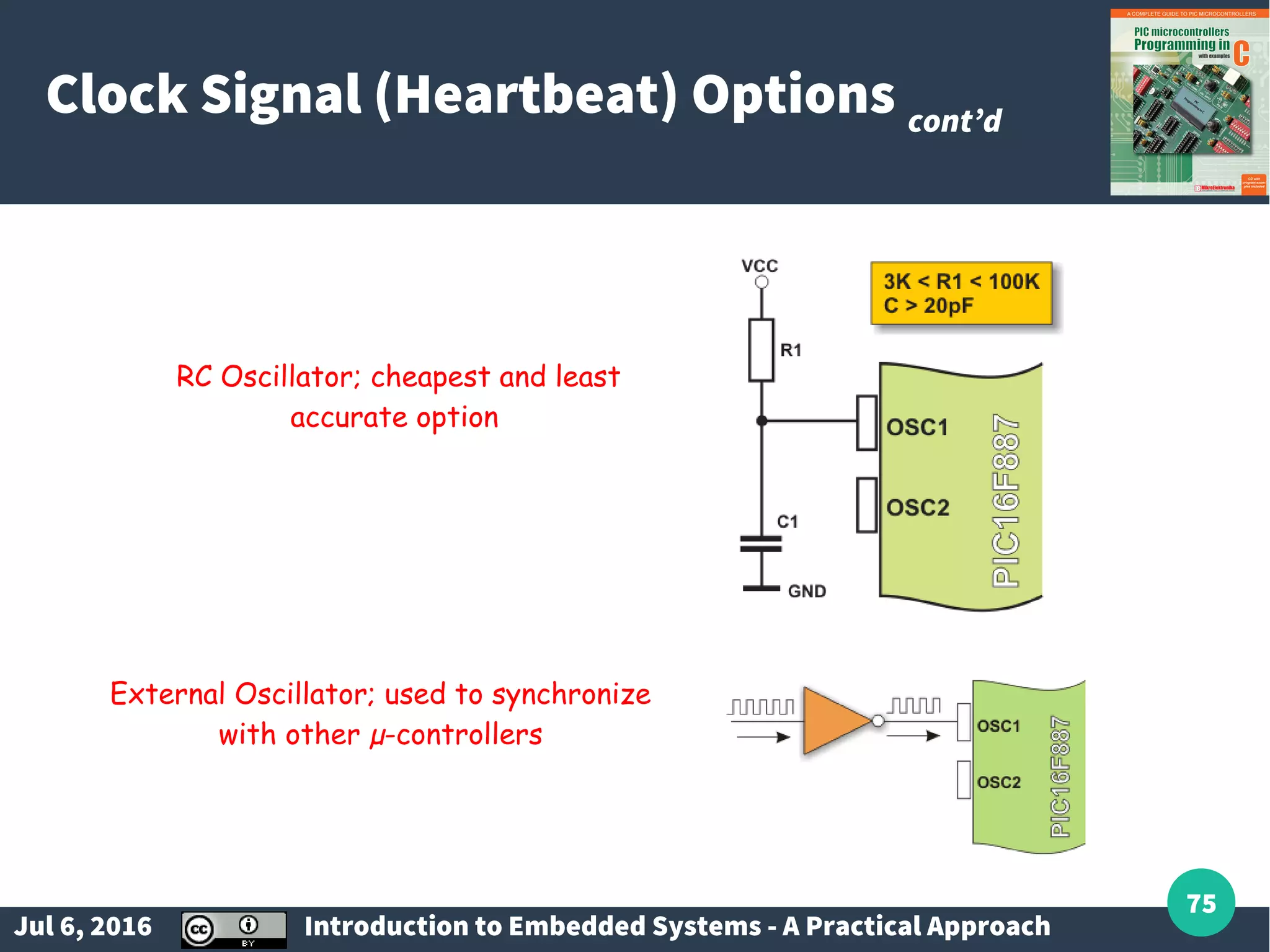
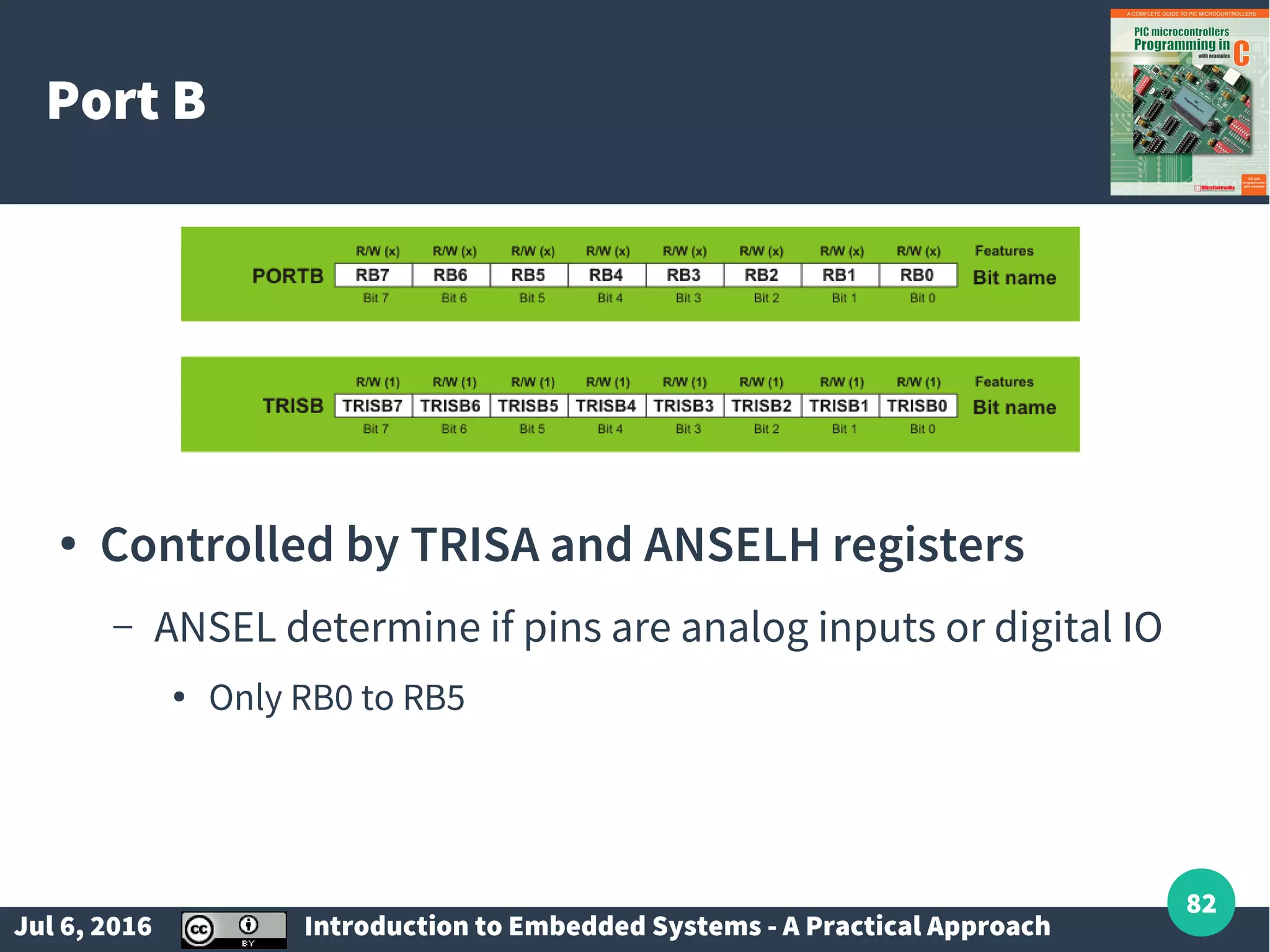
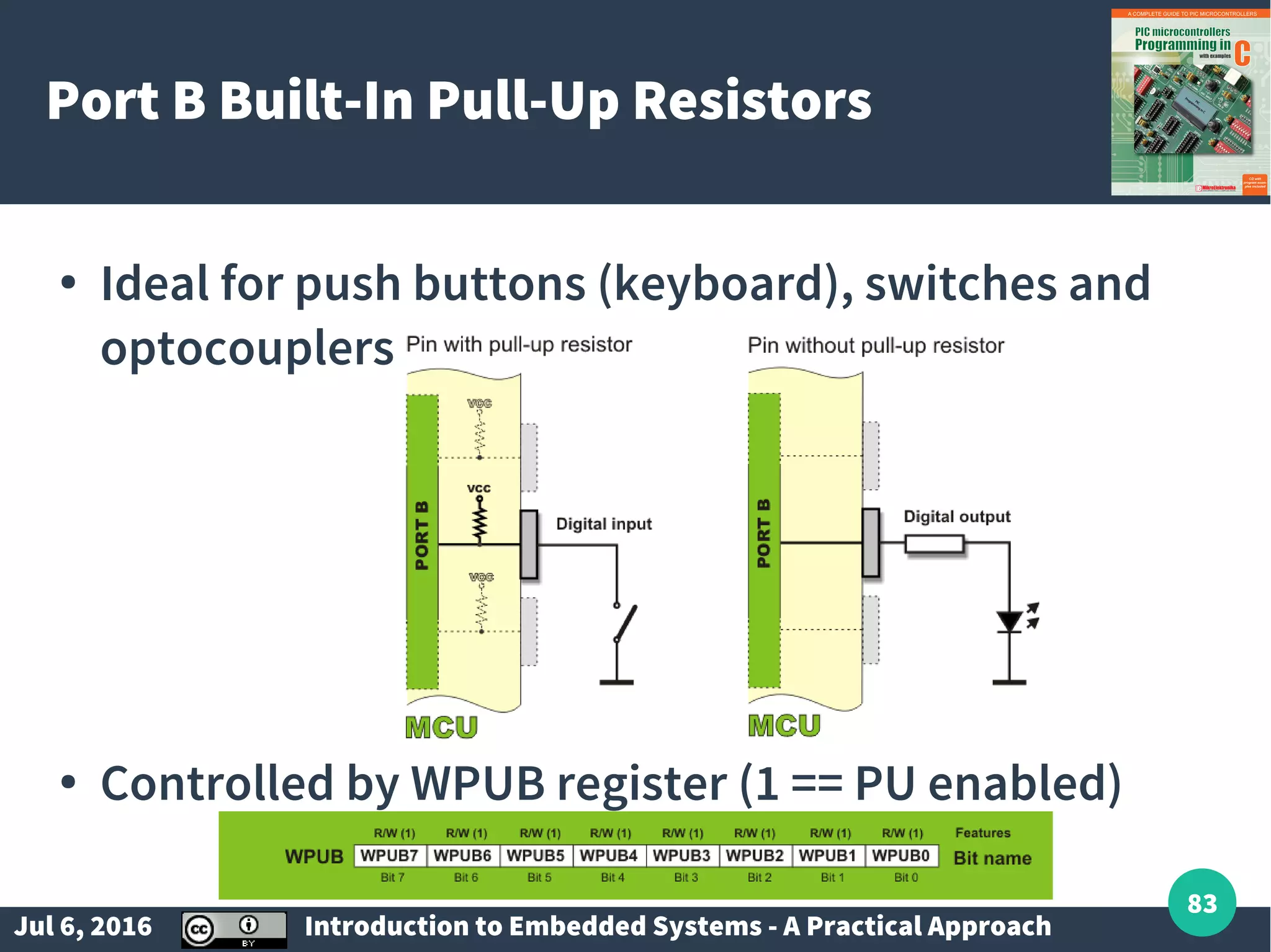
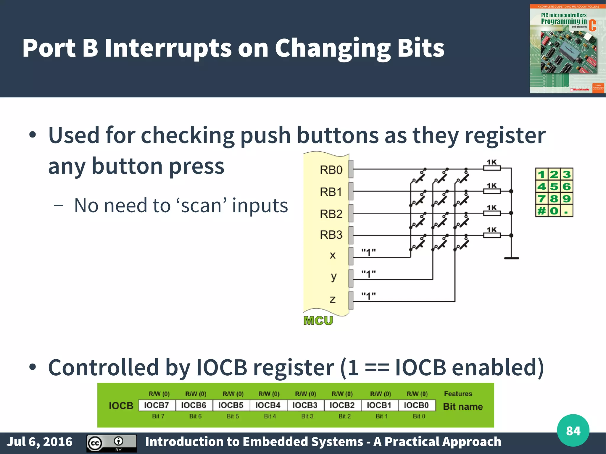
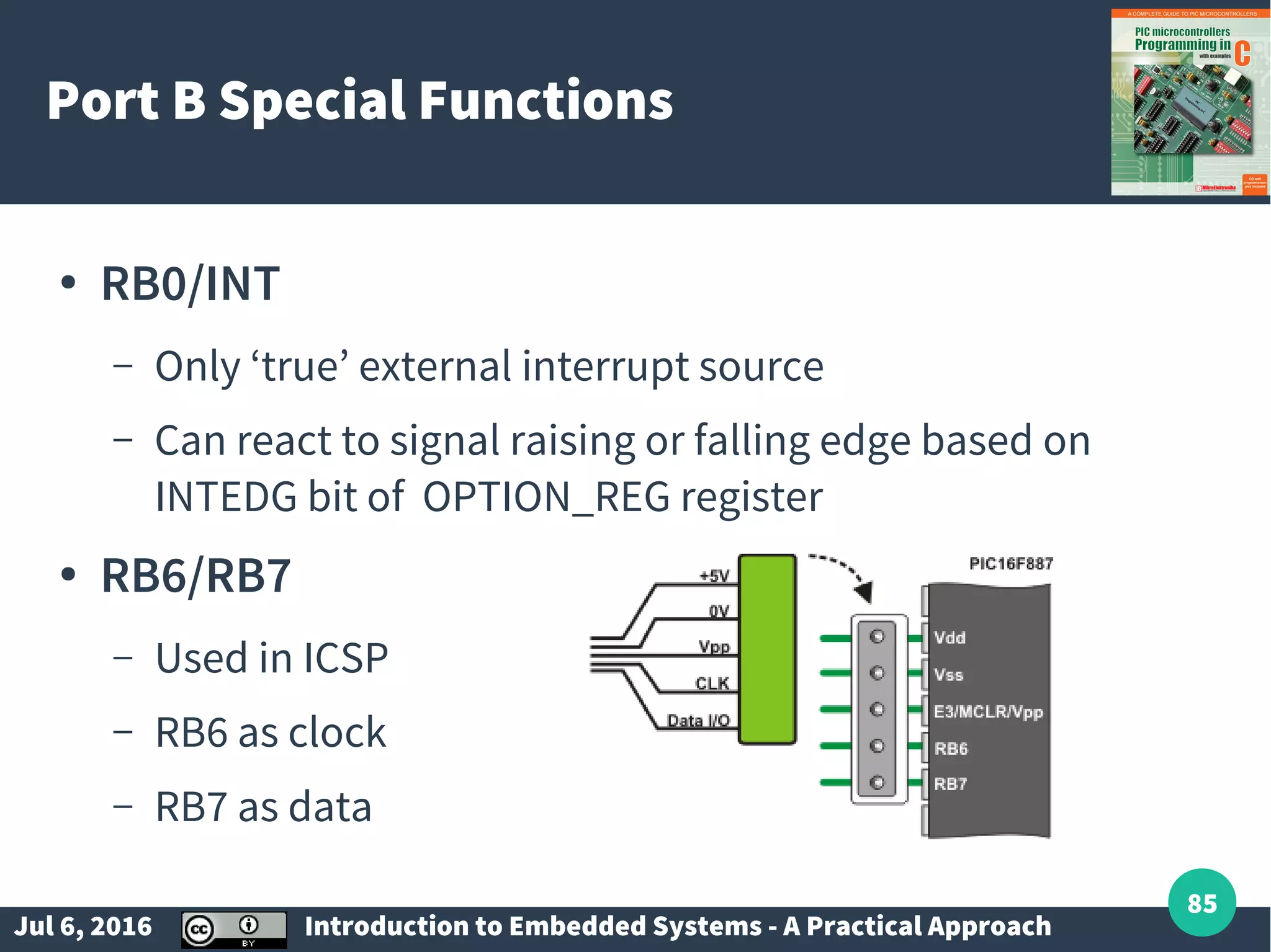
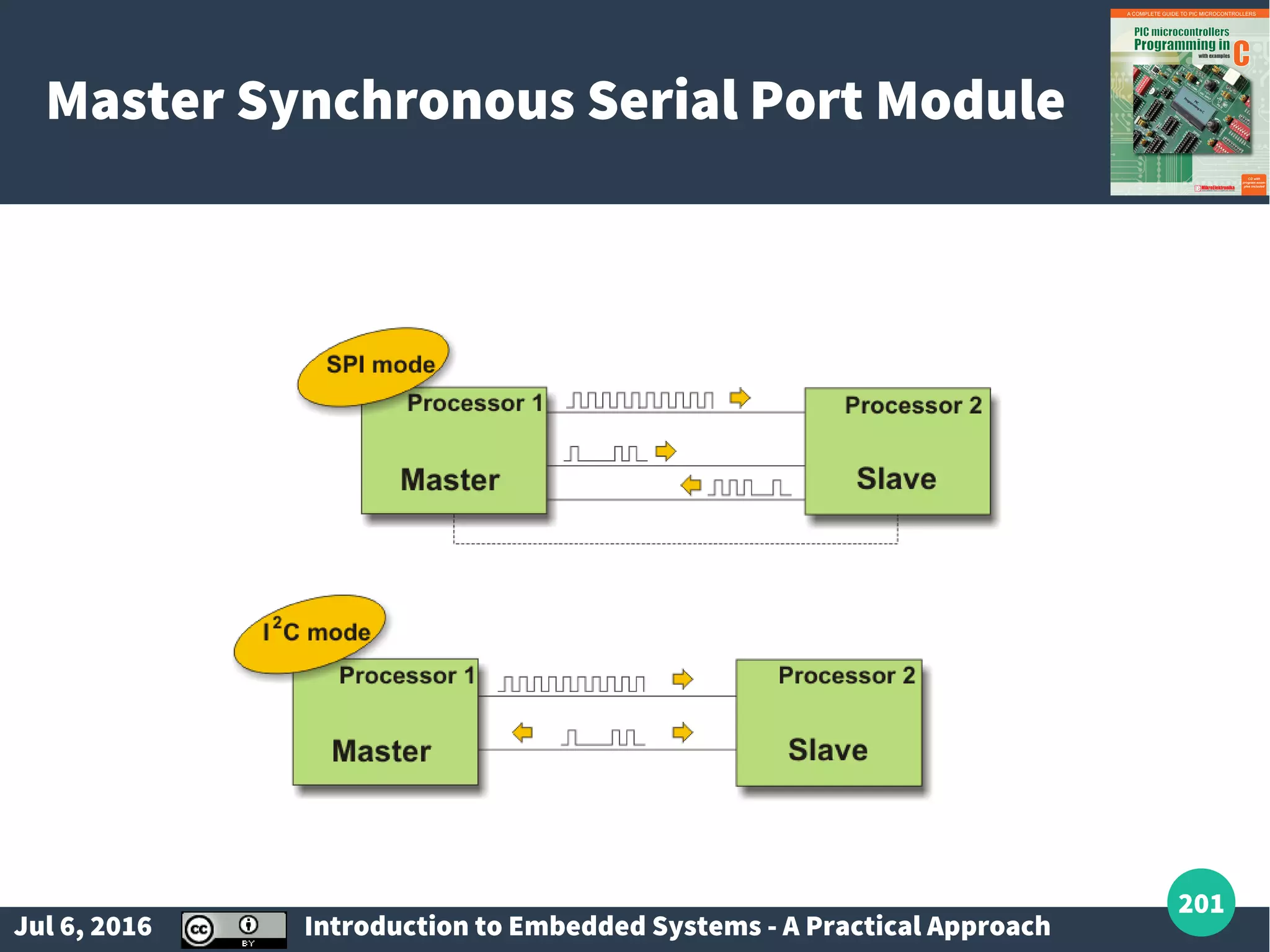
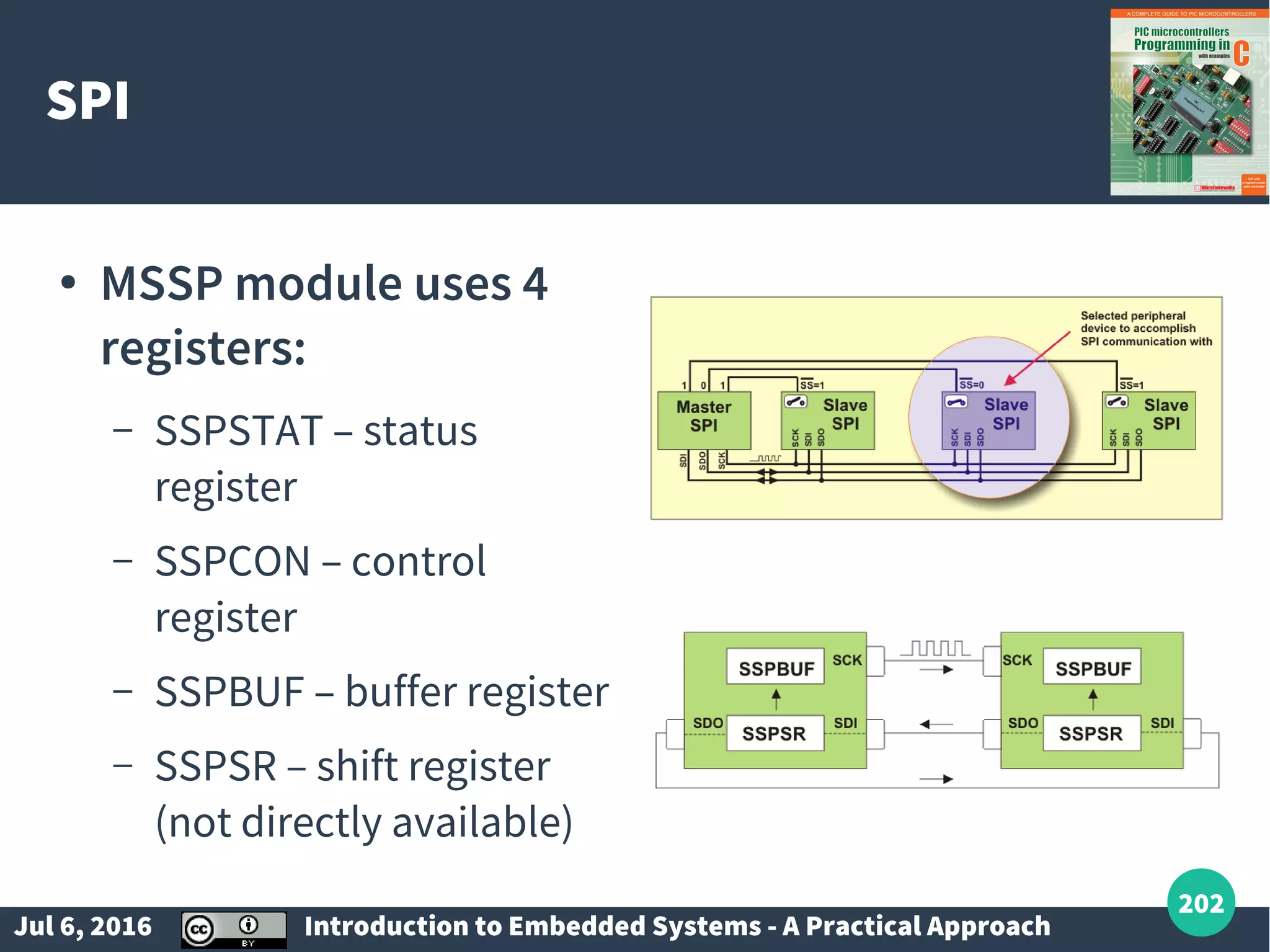
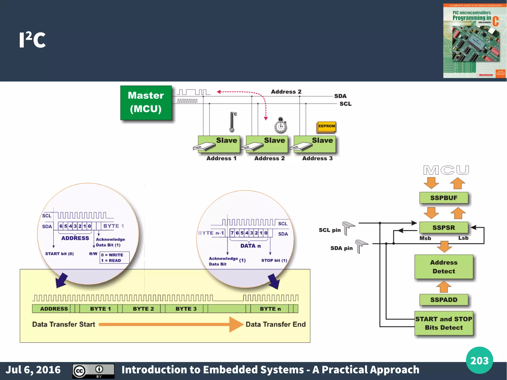
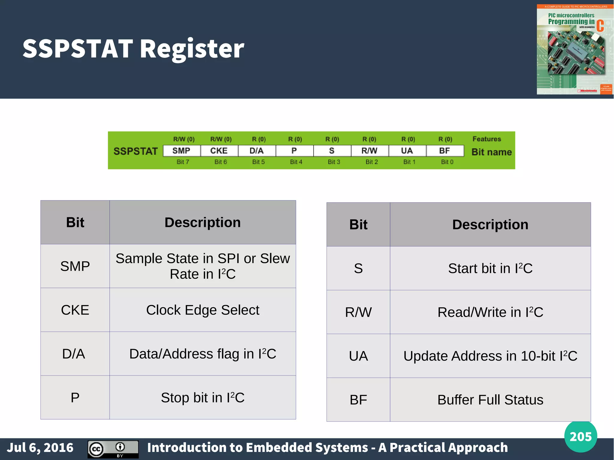
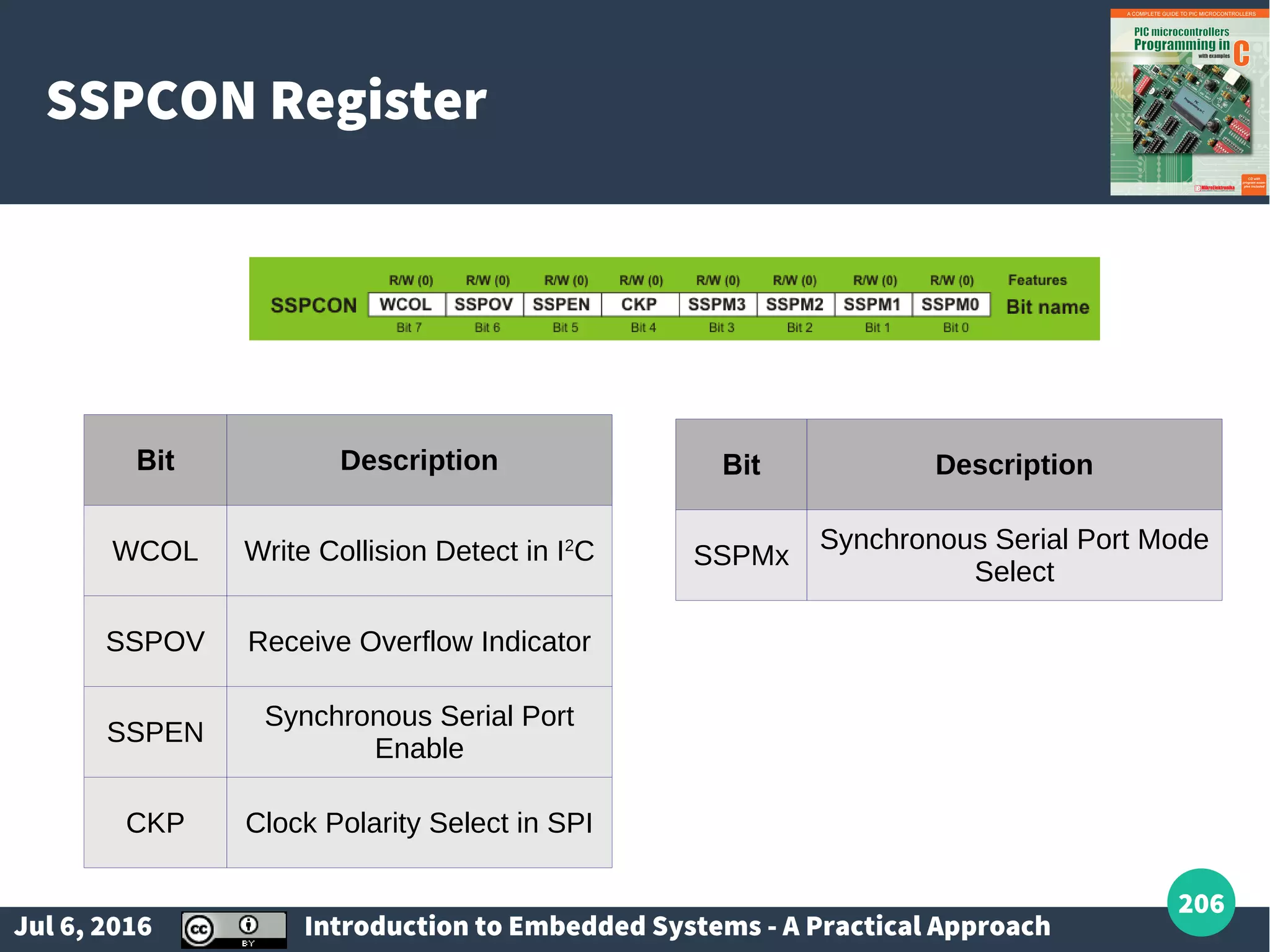
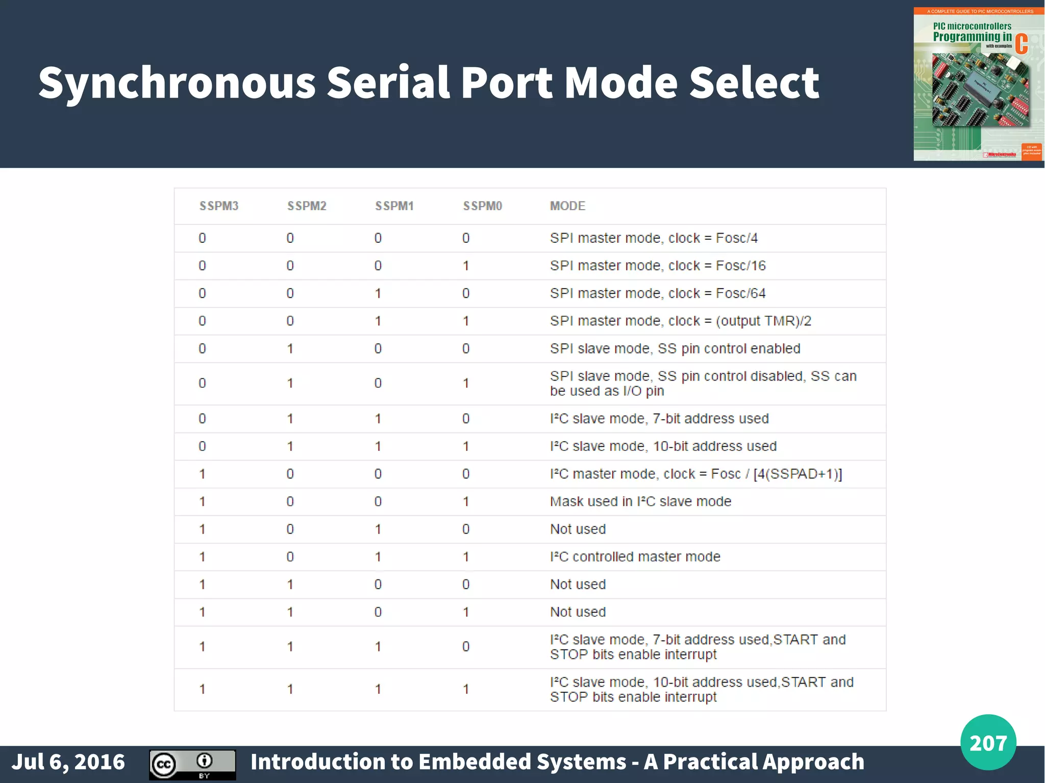
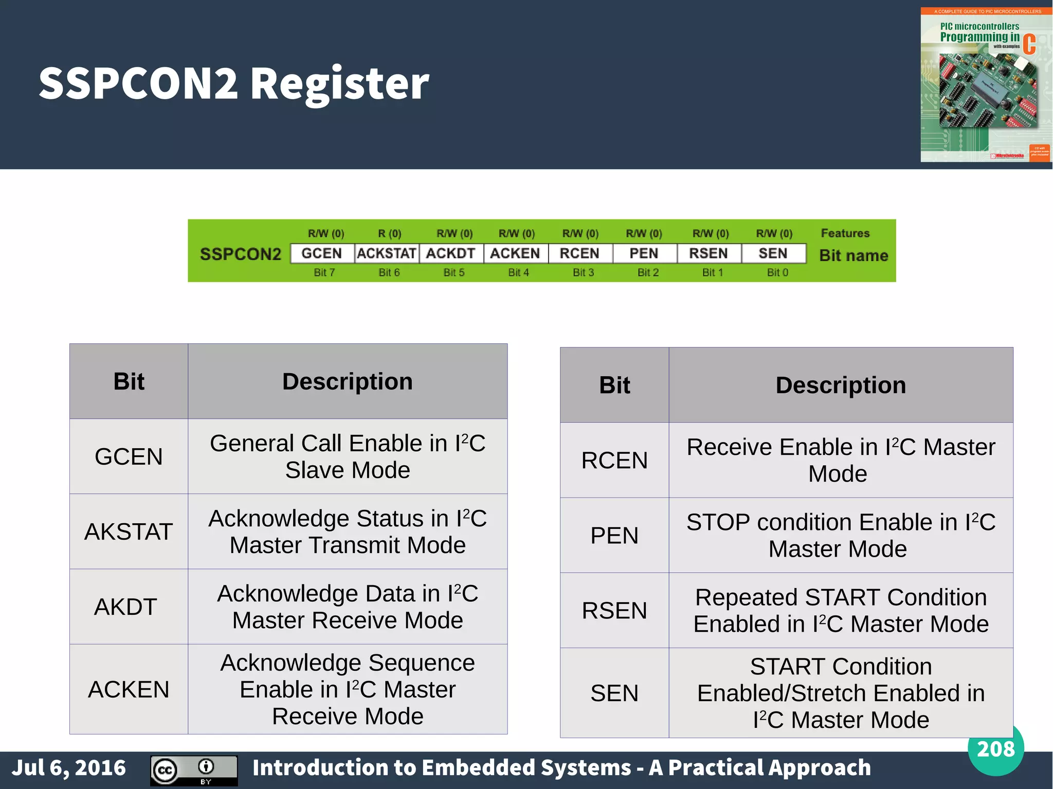
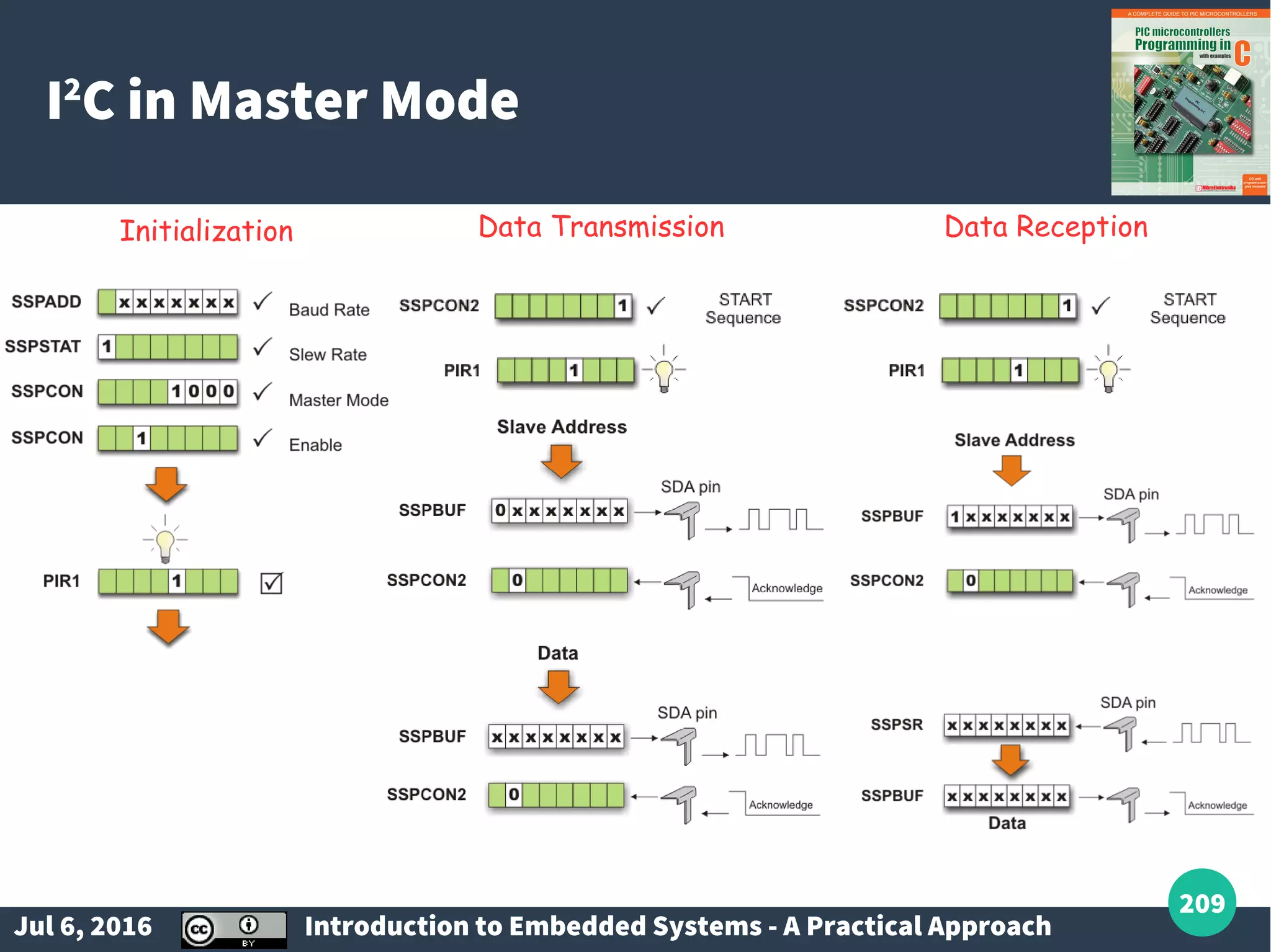
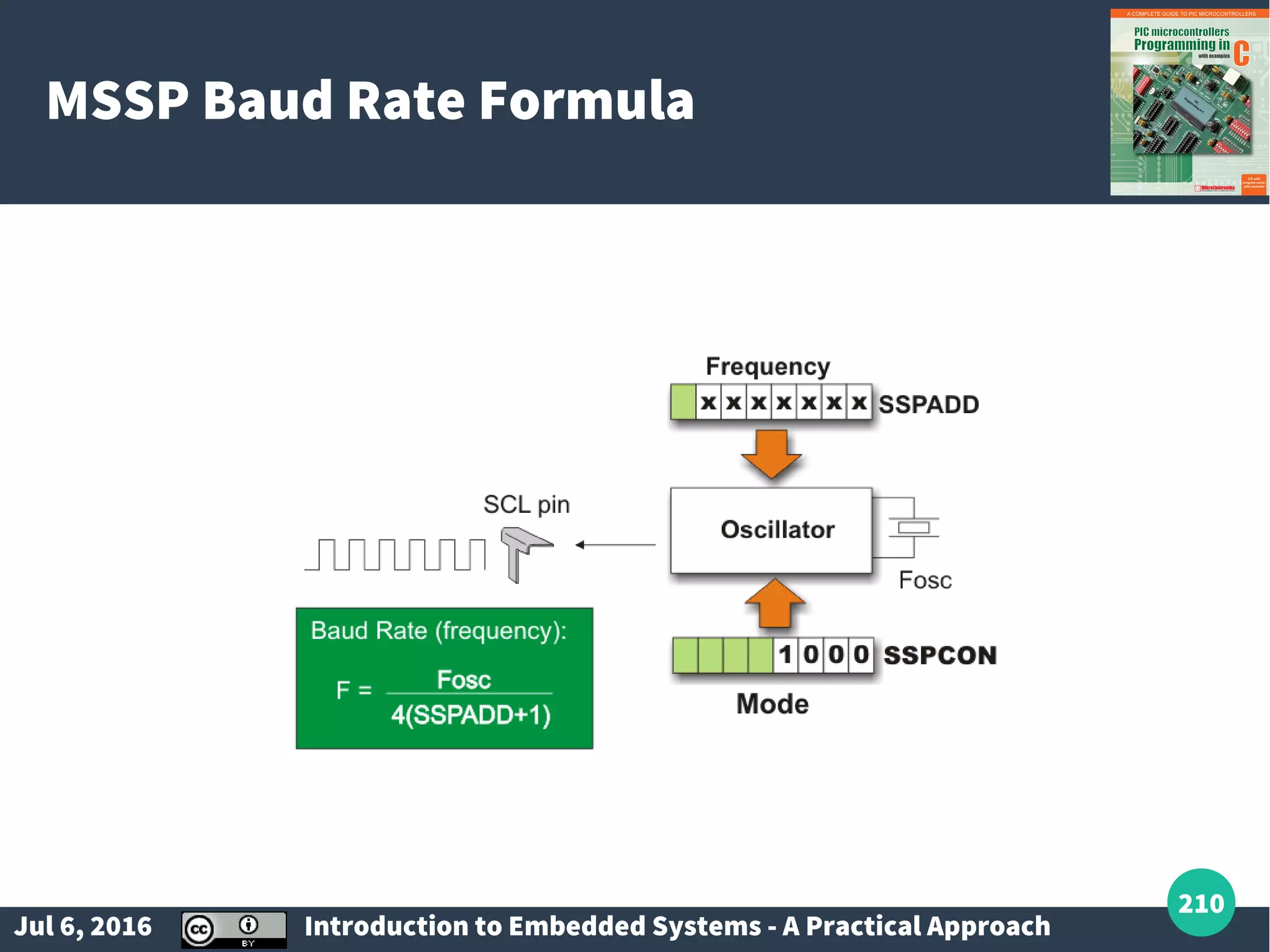
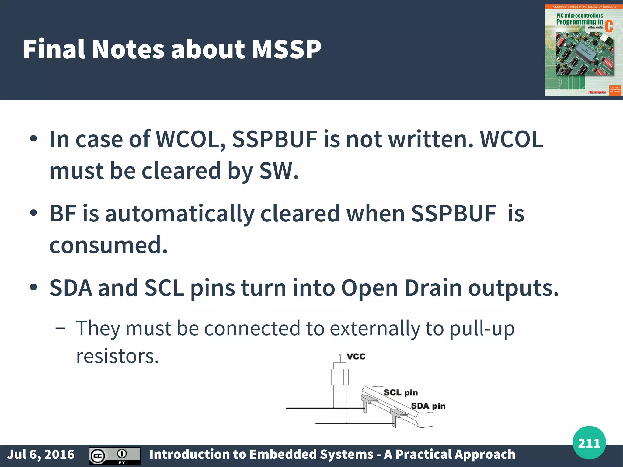
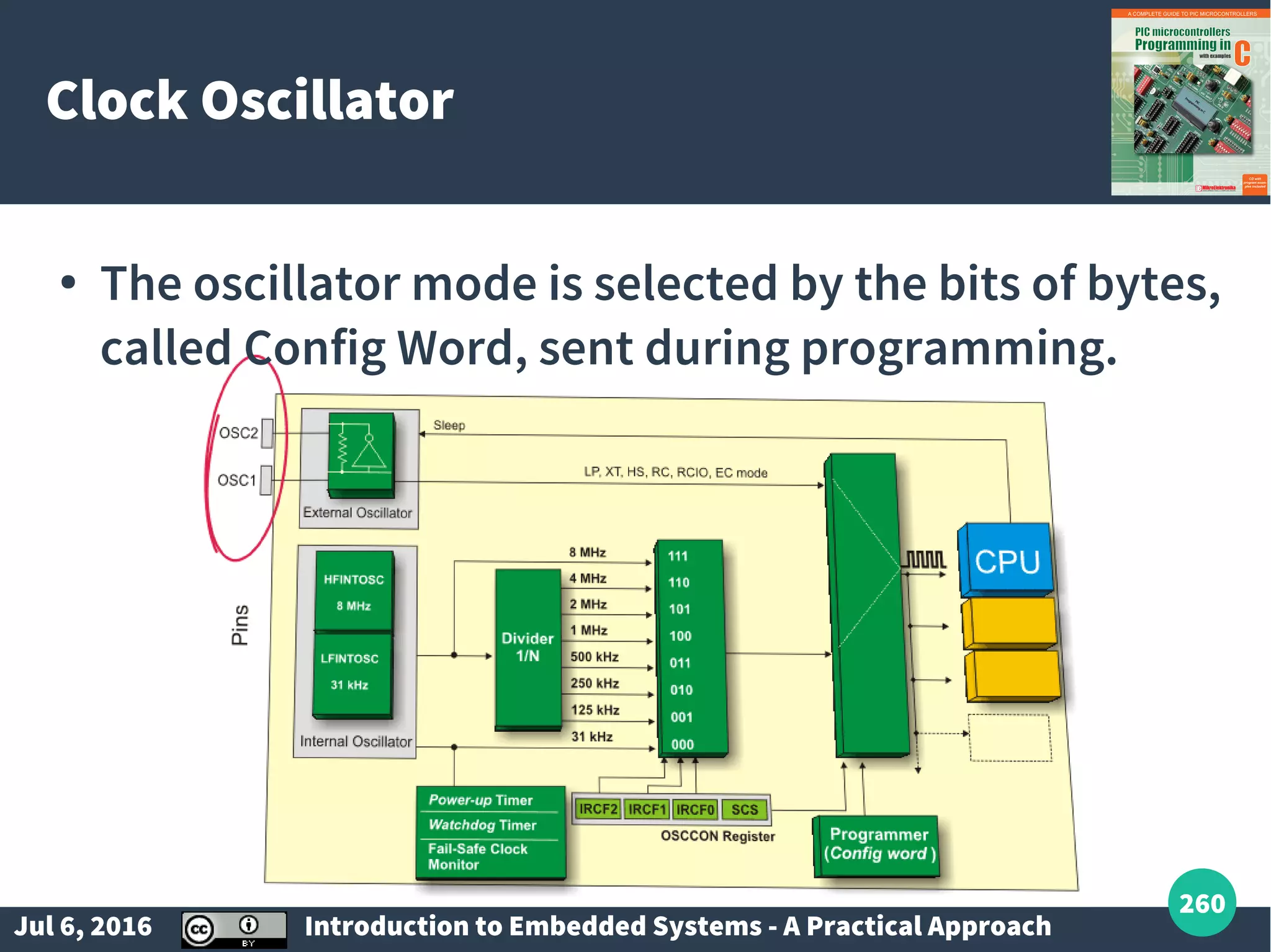
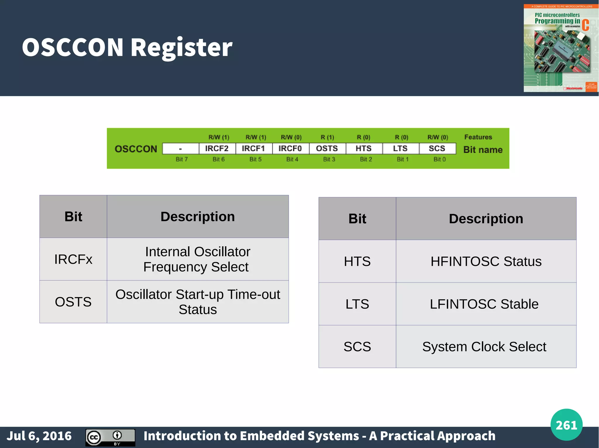
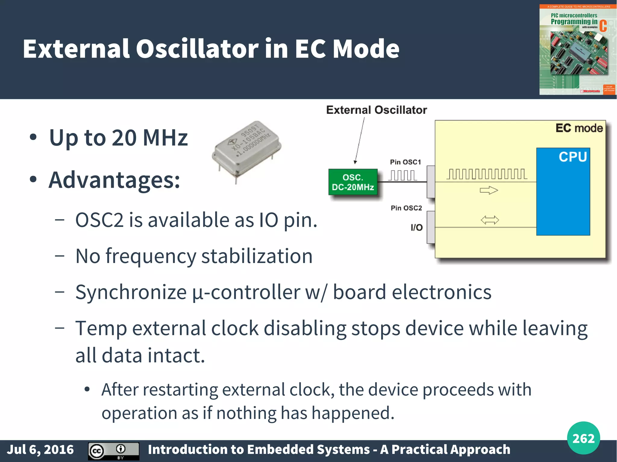
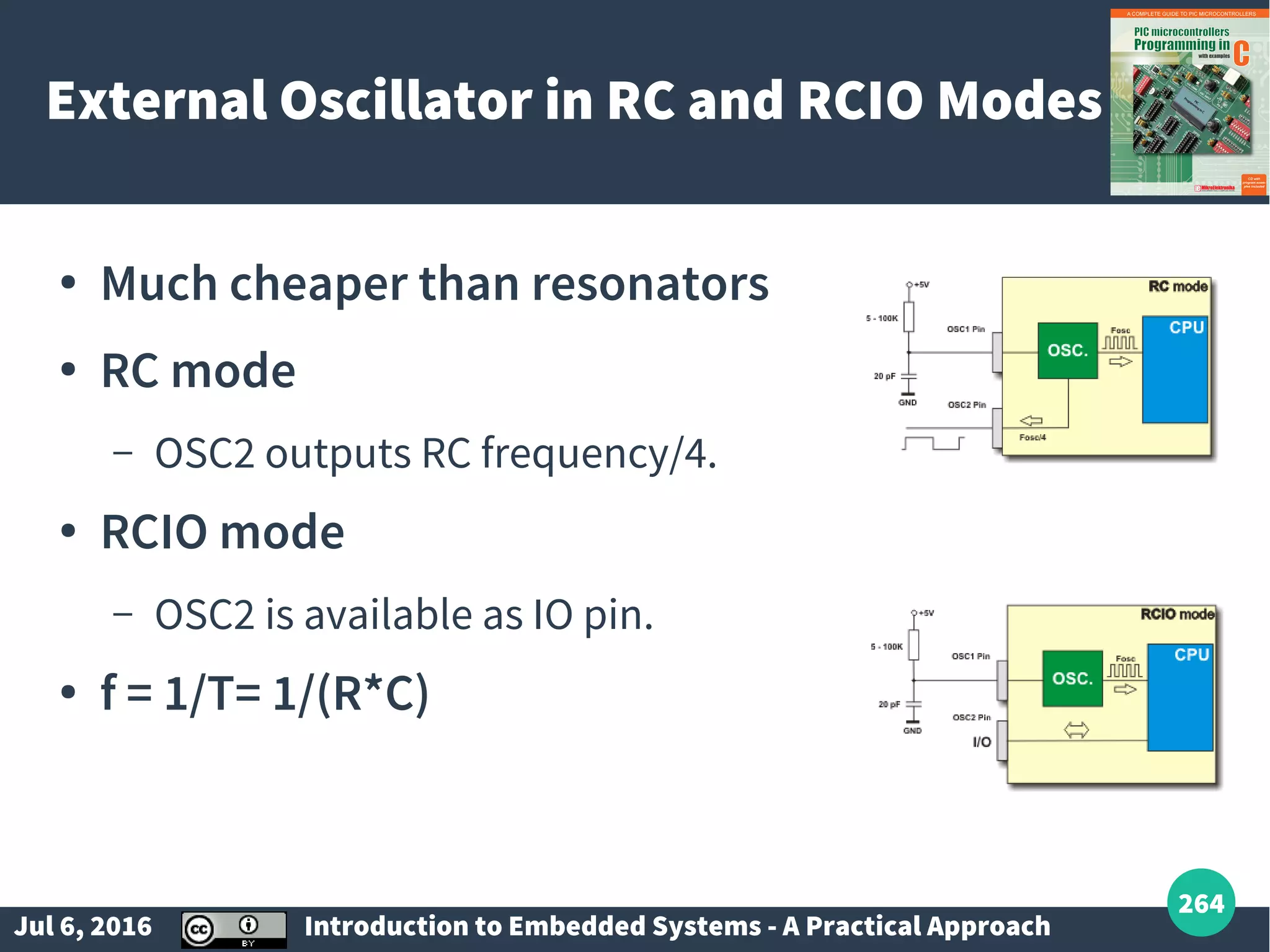
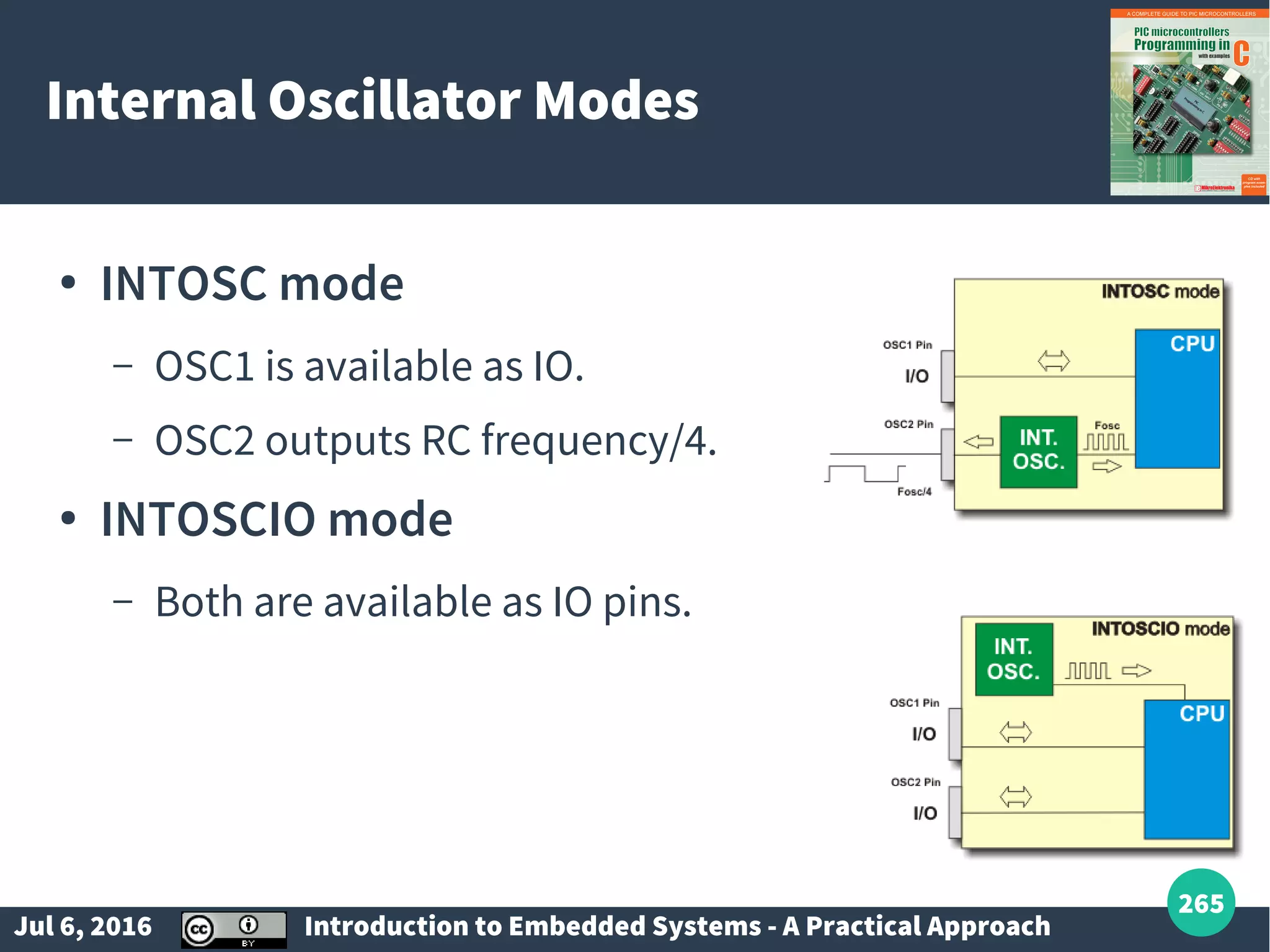
Introduction to microcontrollers, CPU, registers (GPRs and SFRs), IO ports, interrupts, and memory types. Details on volatile and non-volatile memory and basics of serial communication protocols.
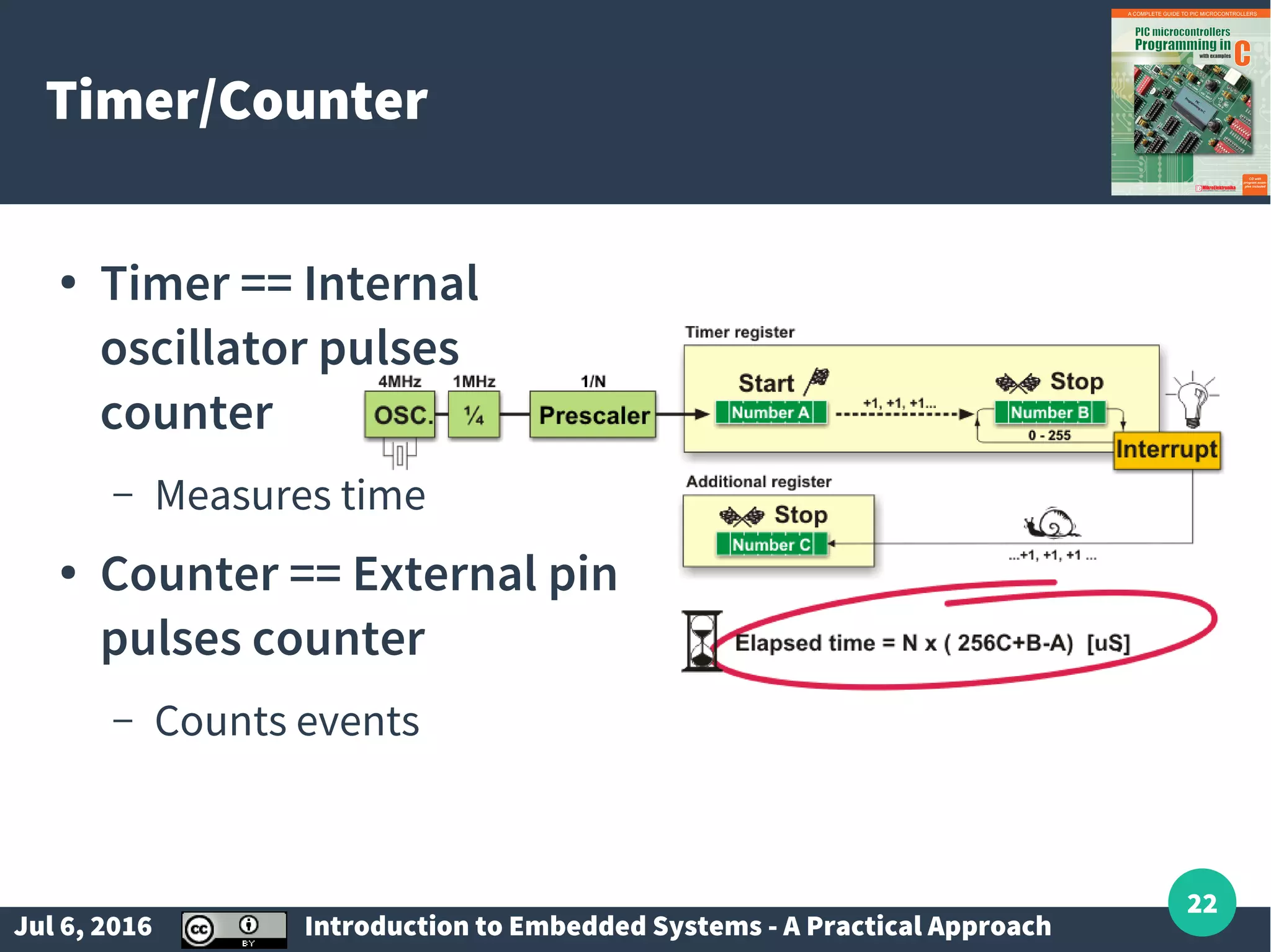
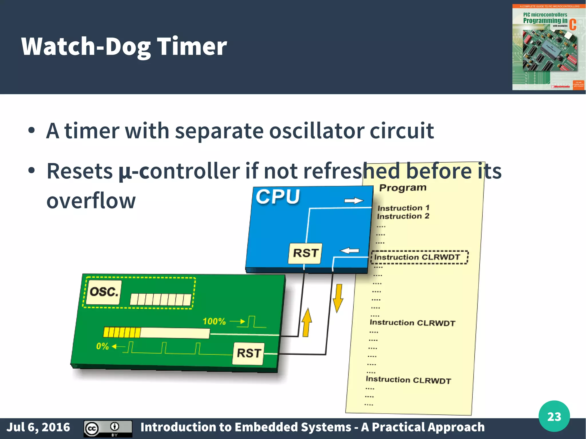
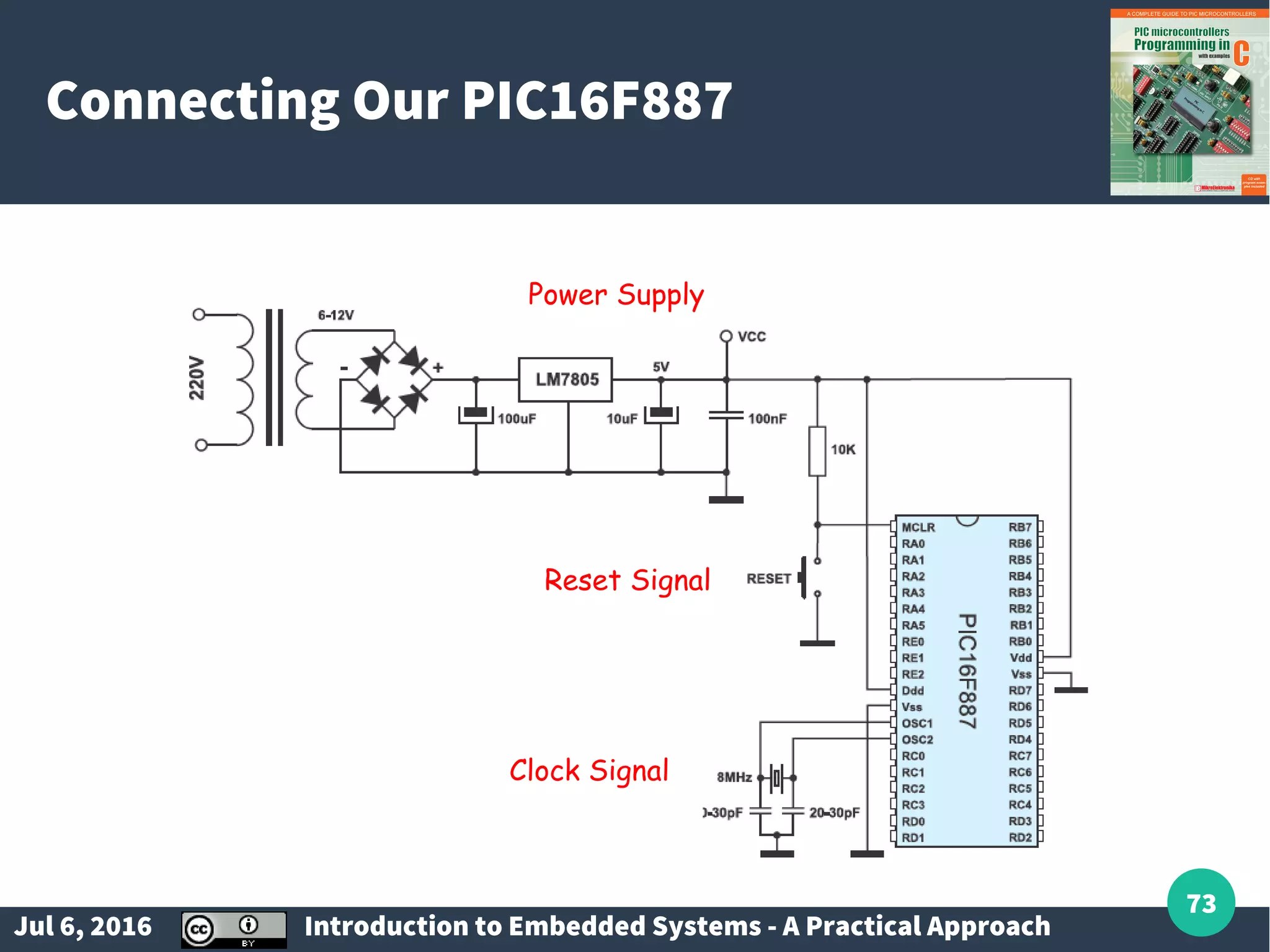
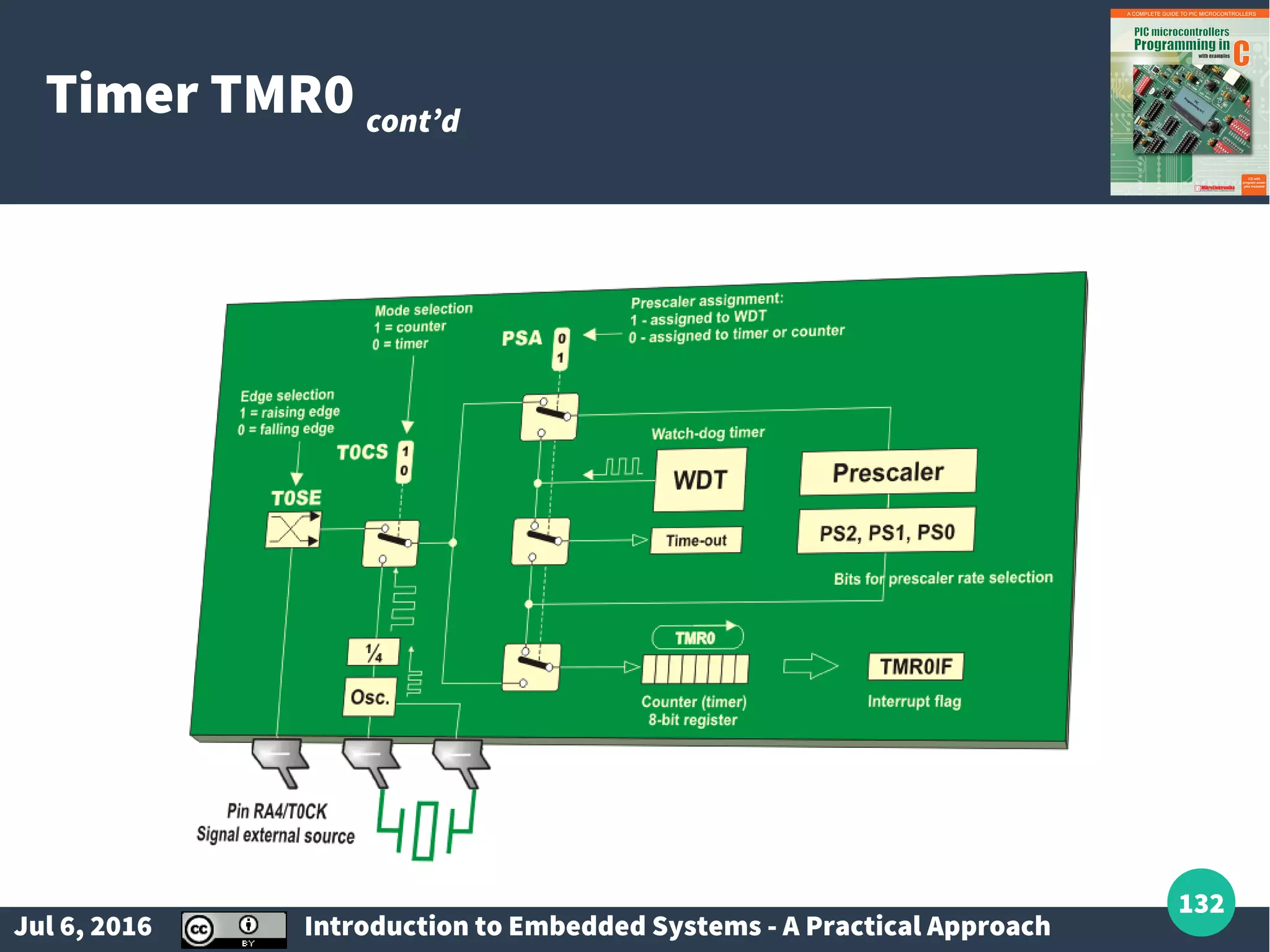
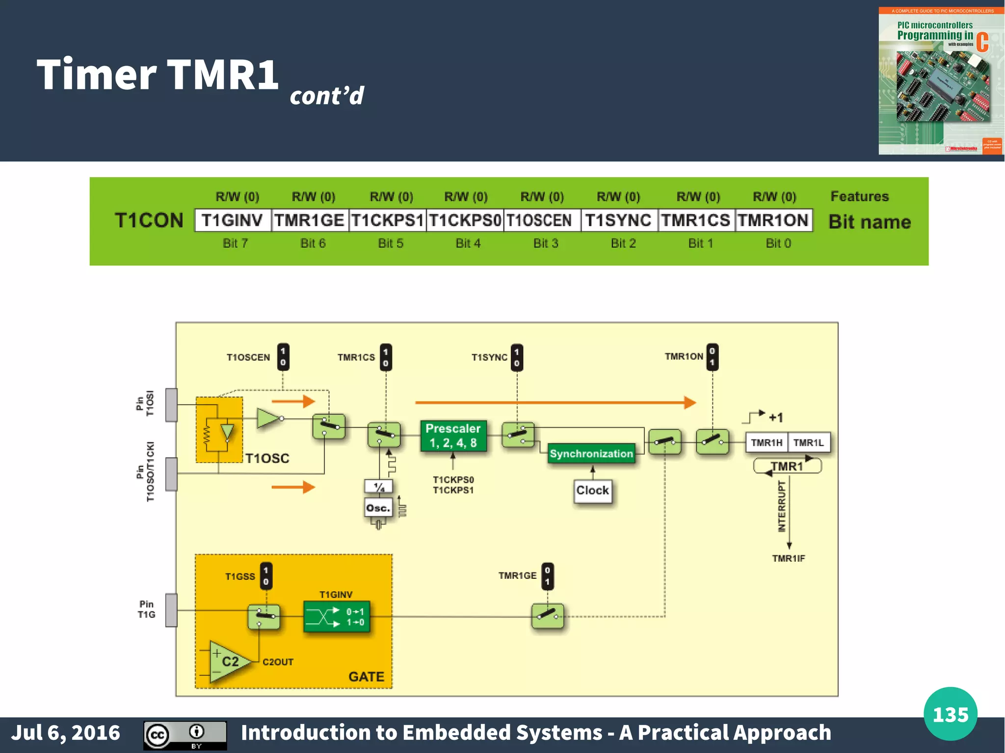
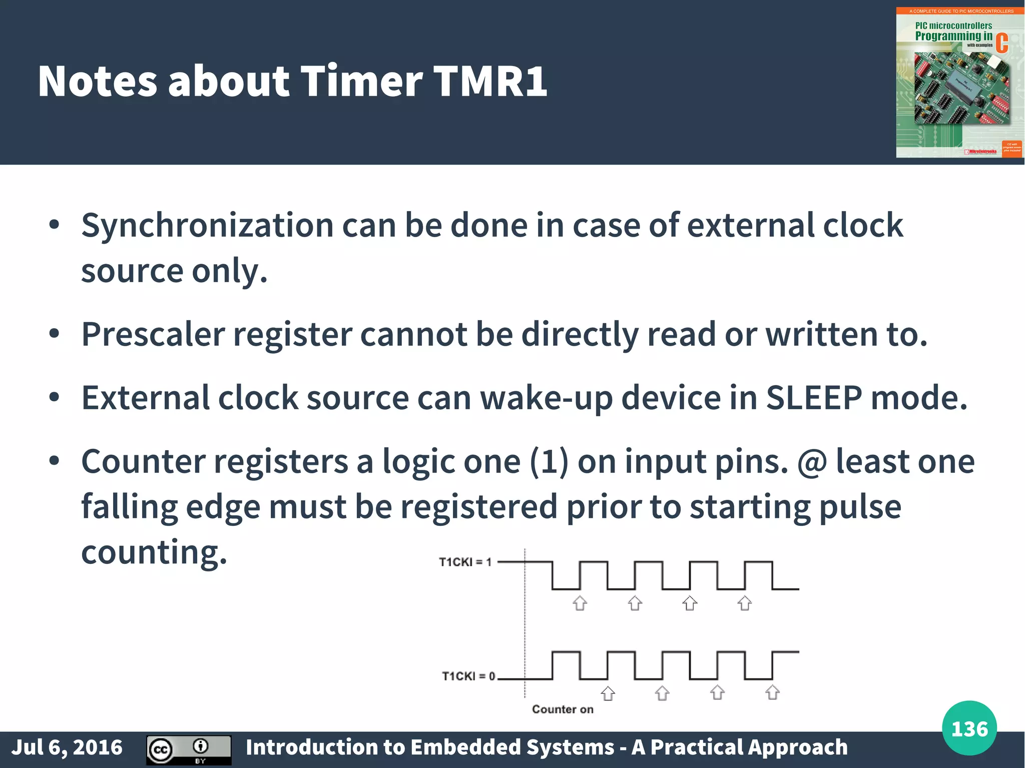
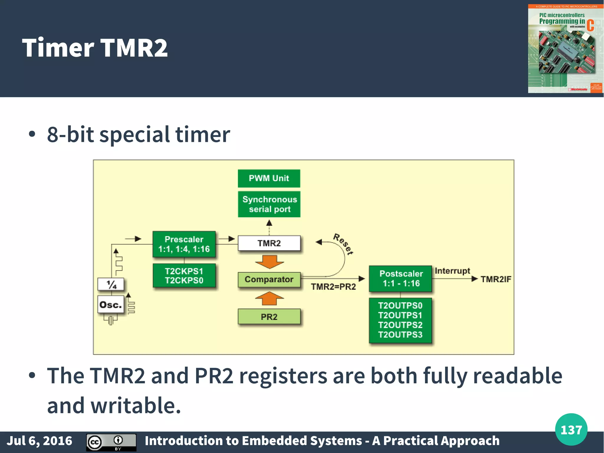
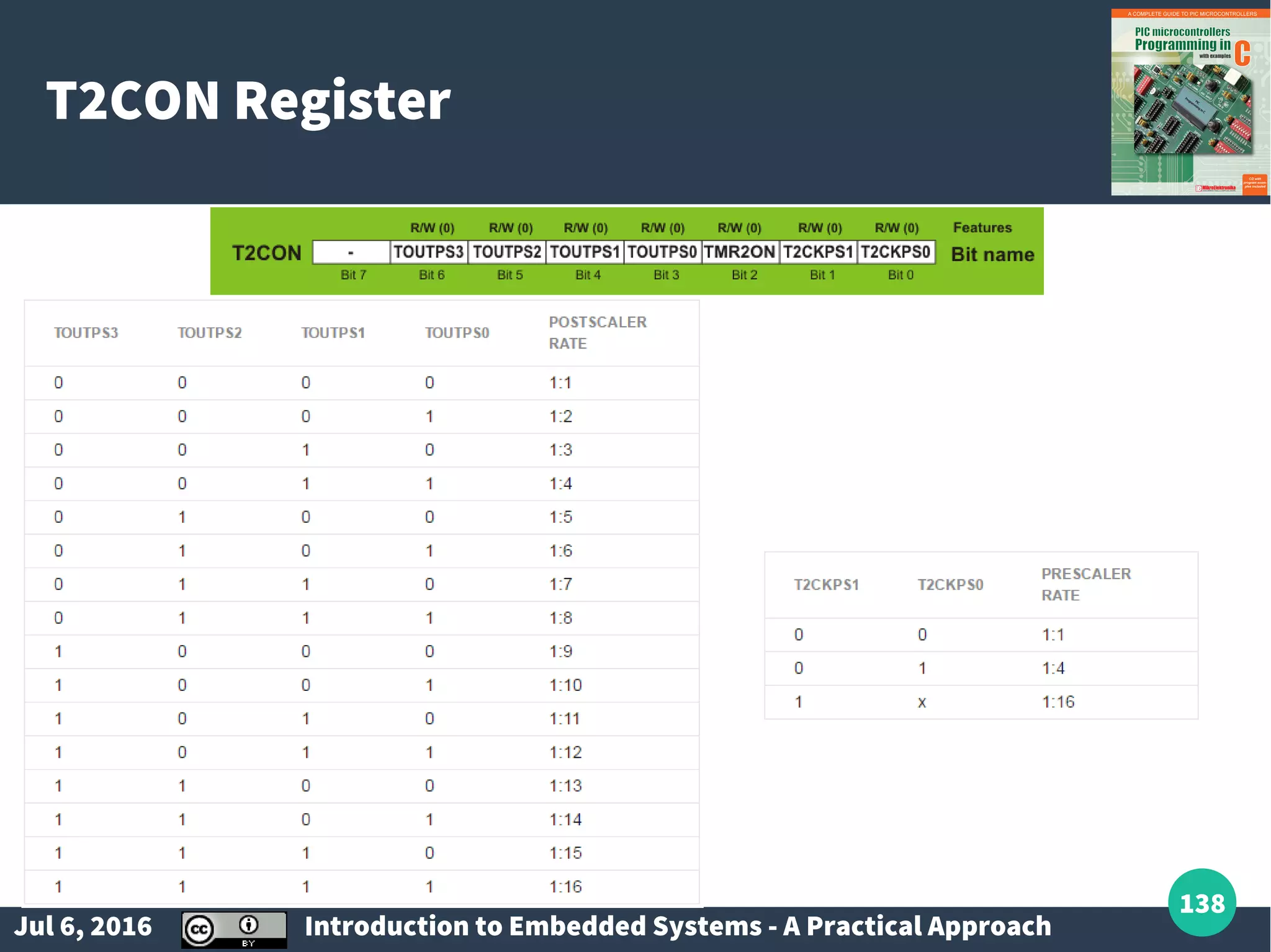
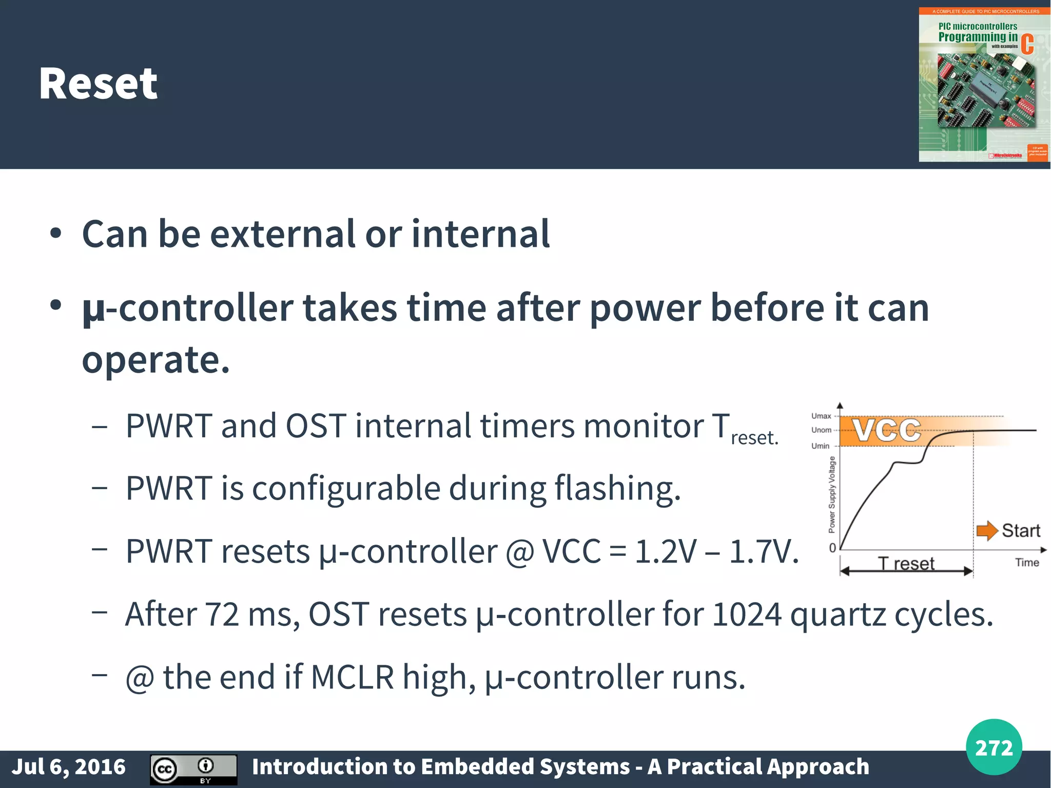
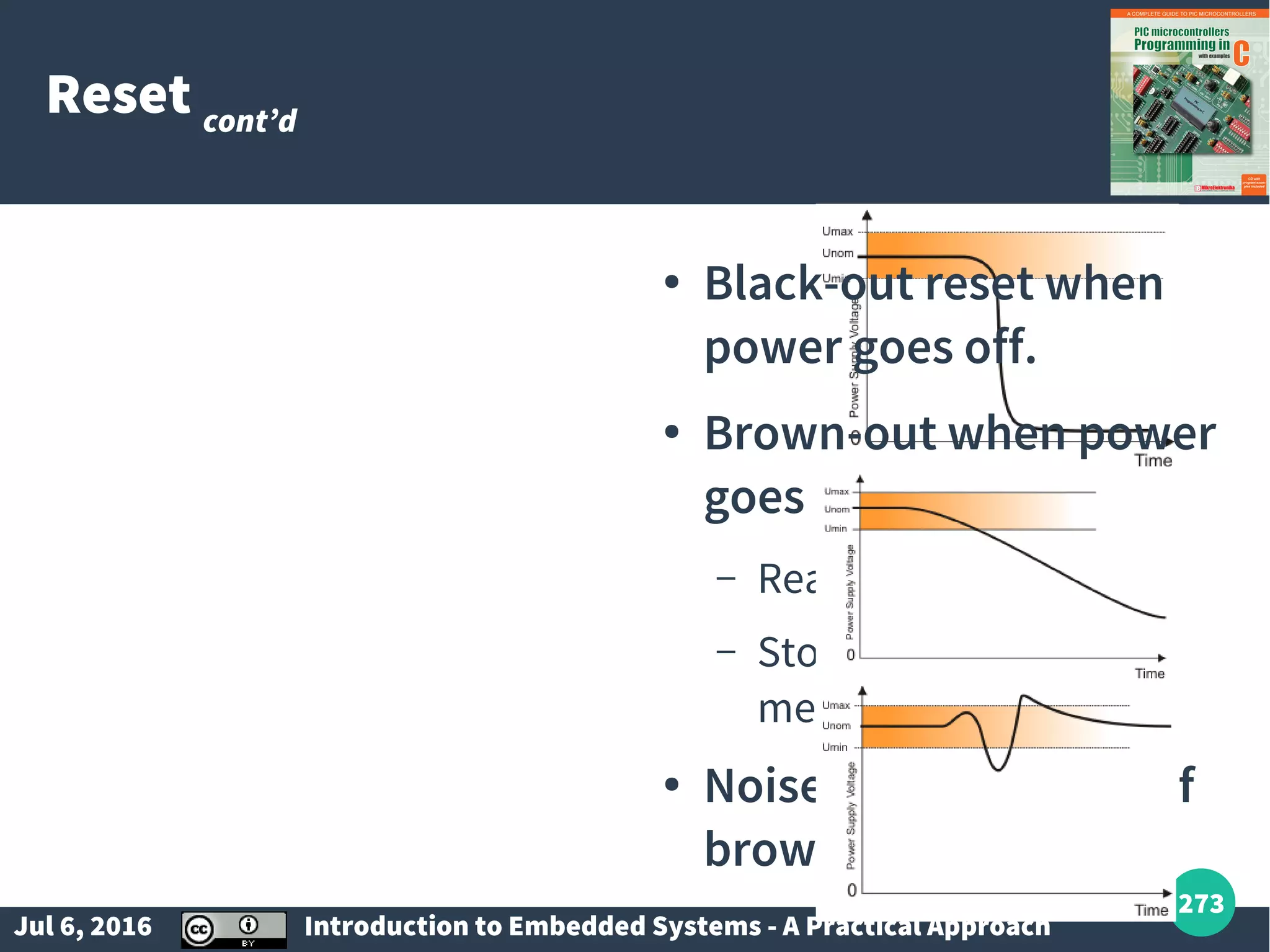
Power supply circuits, reset mechanisms, timers/counters, and watchdog timers.
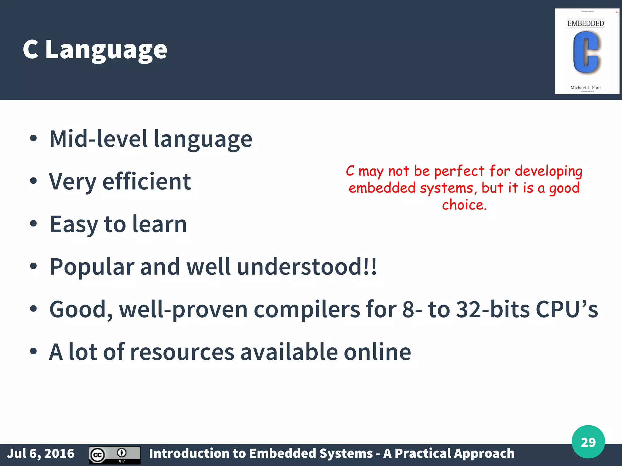
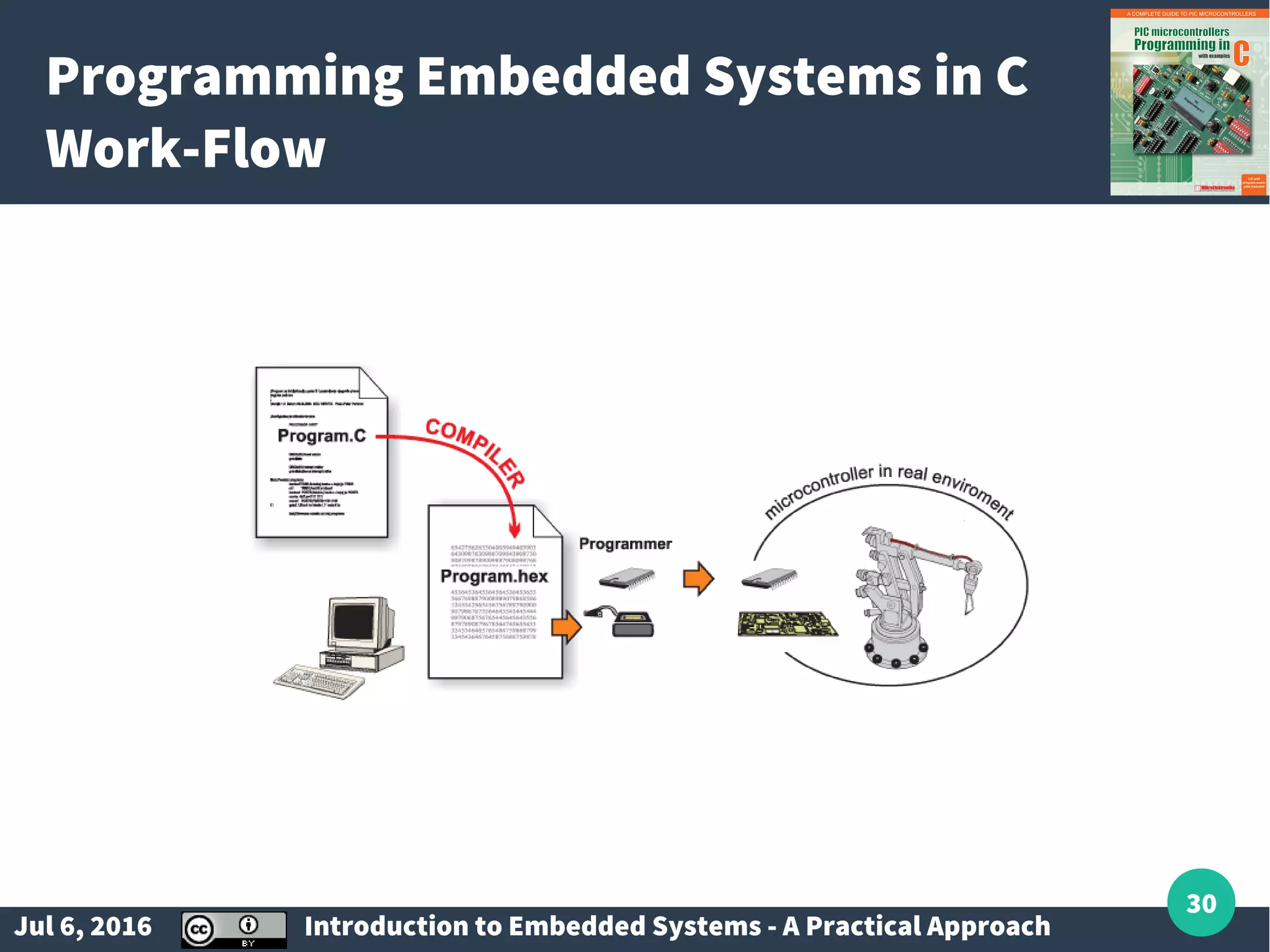
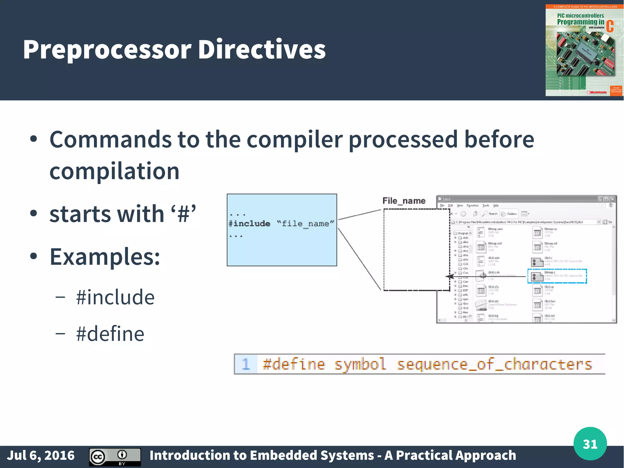
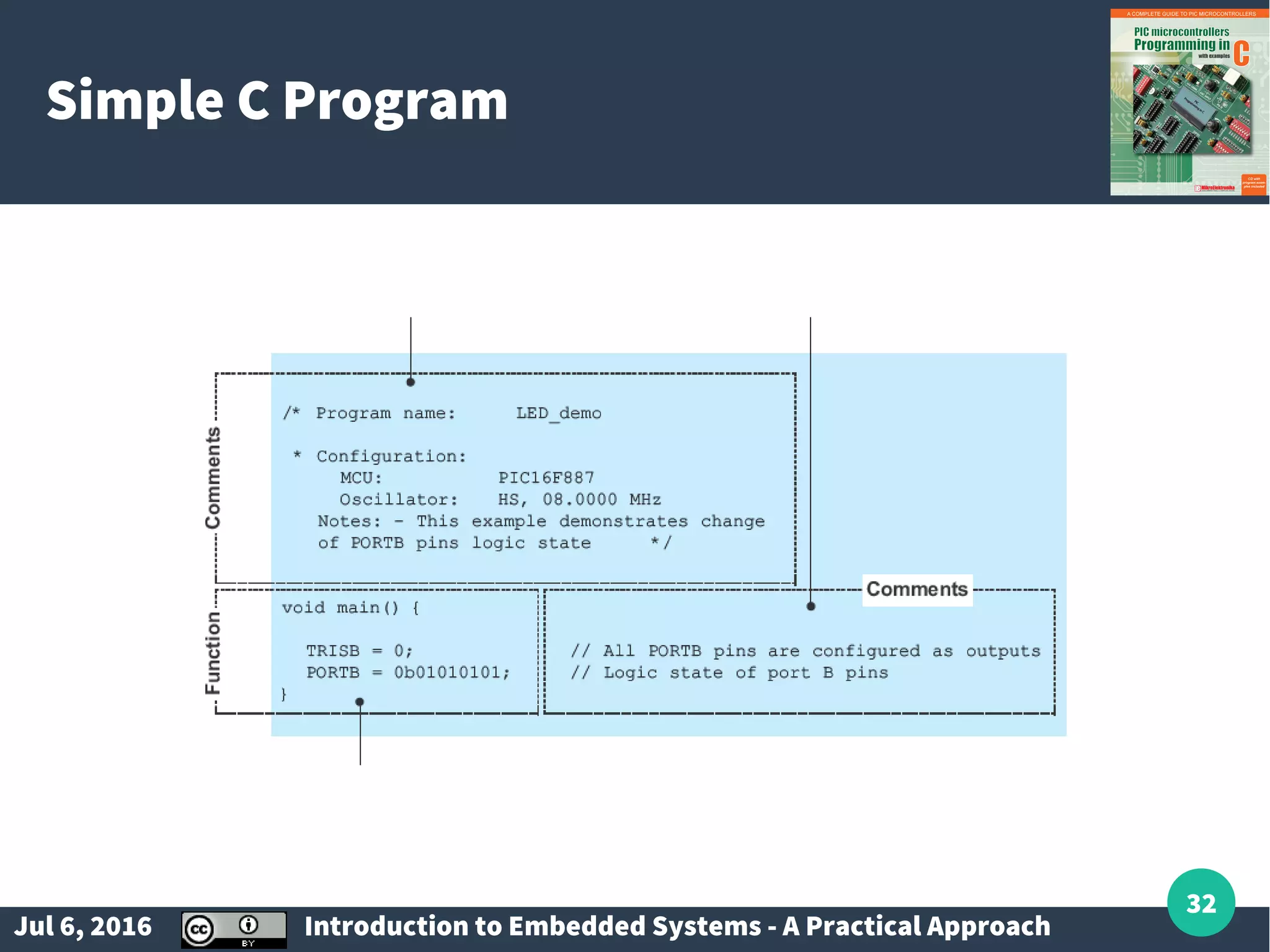
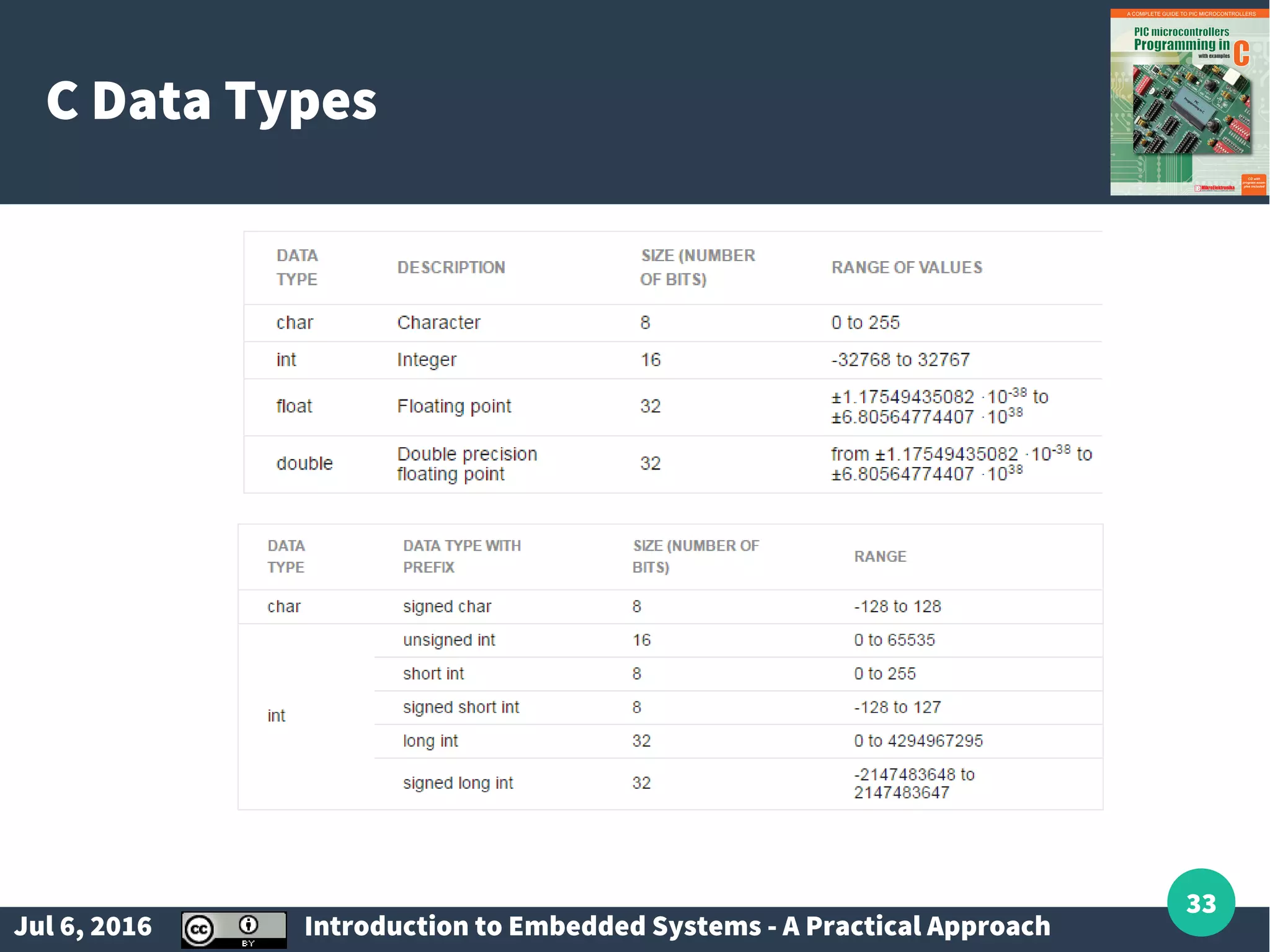
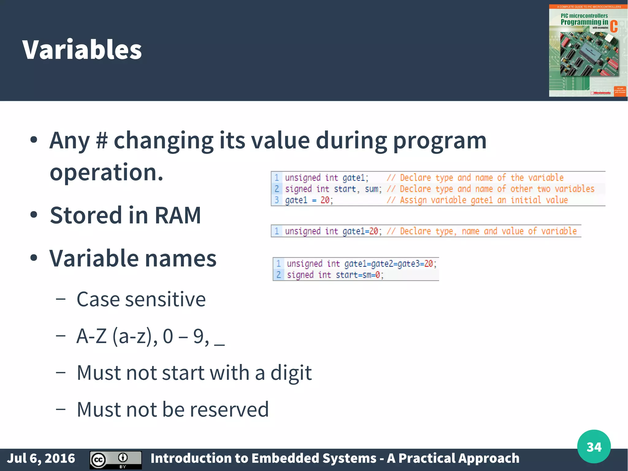
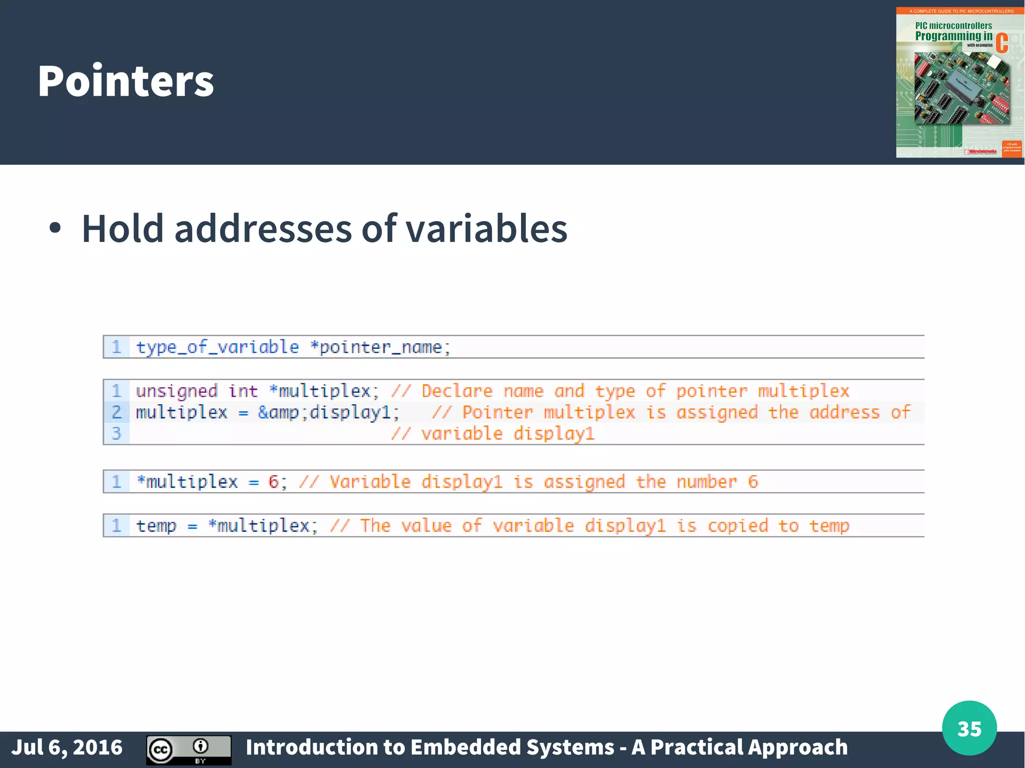
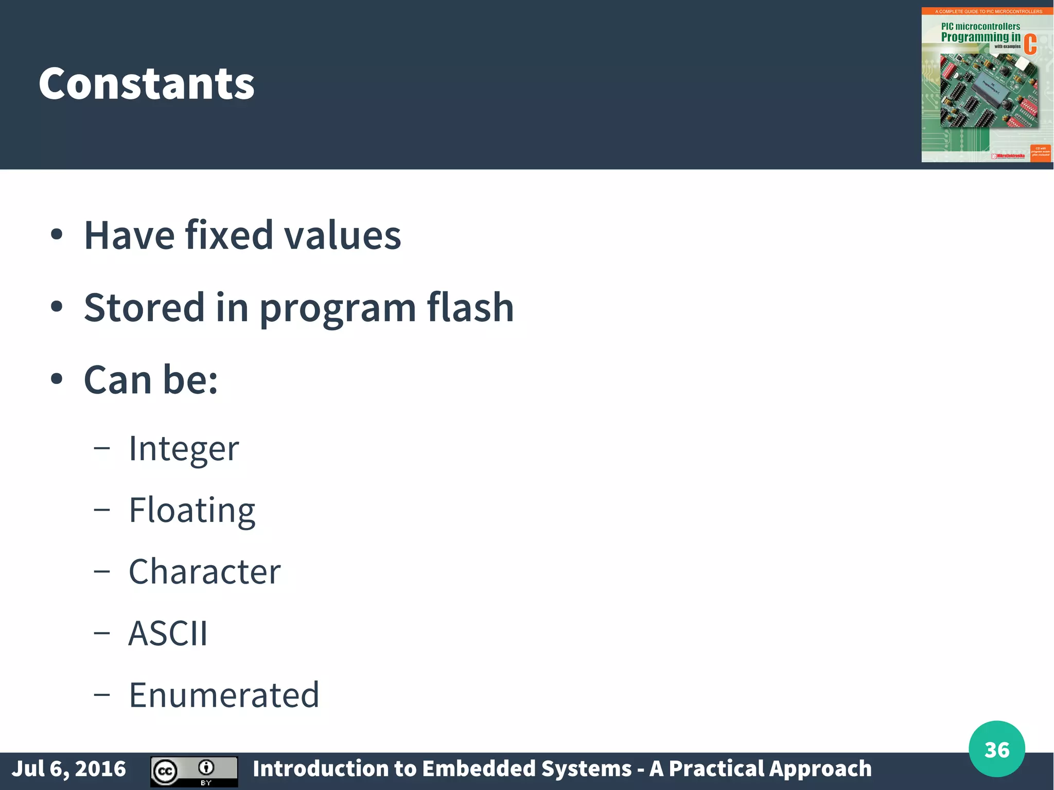
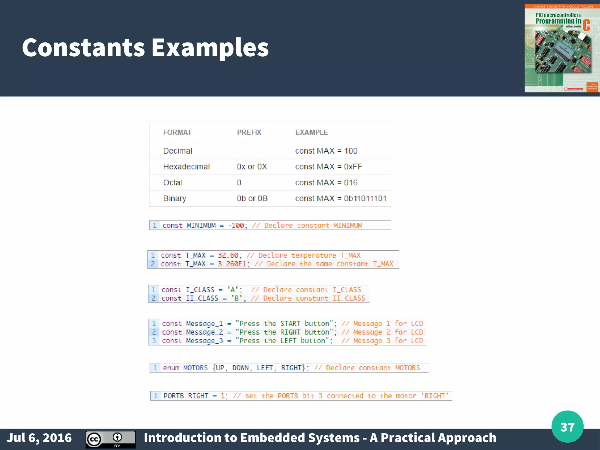
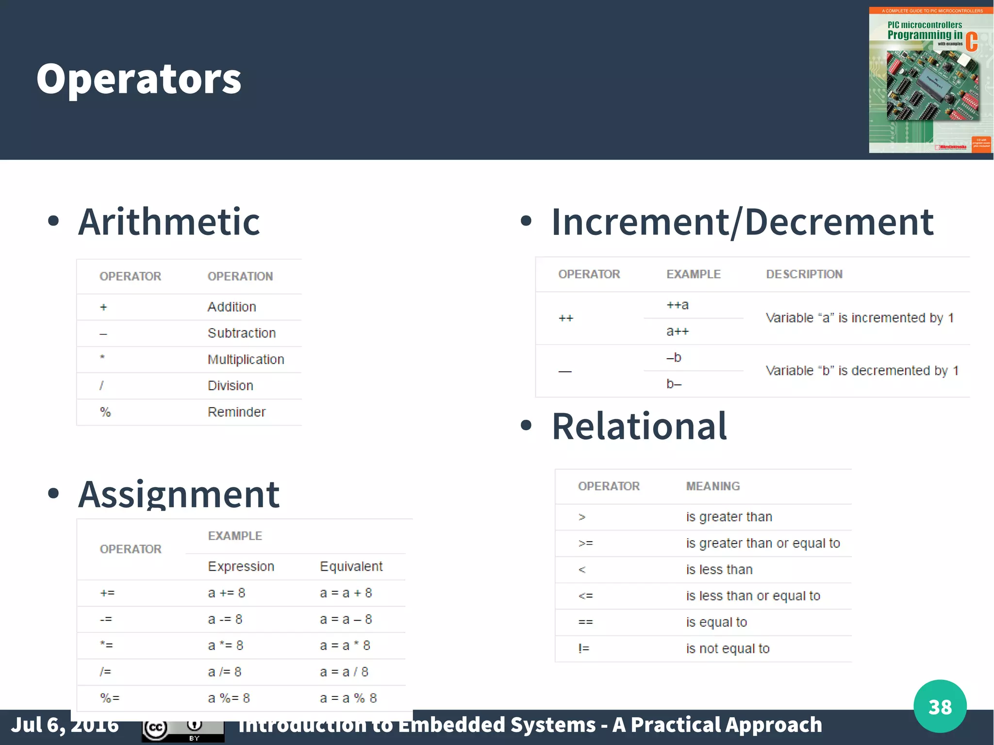
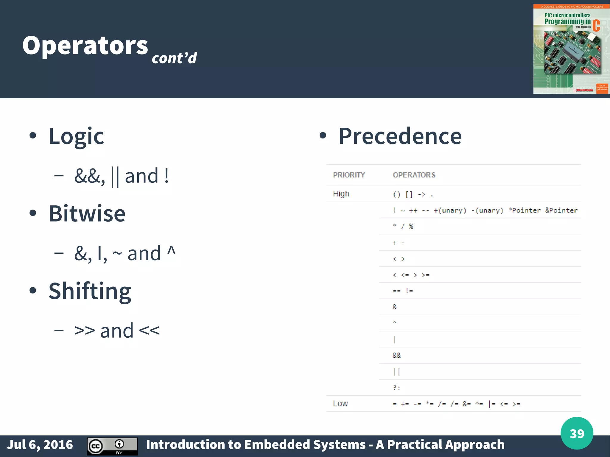
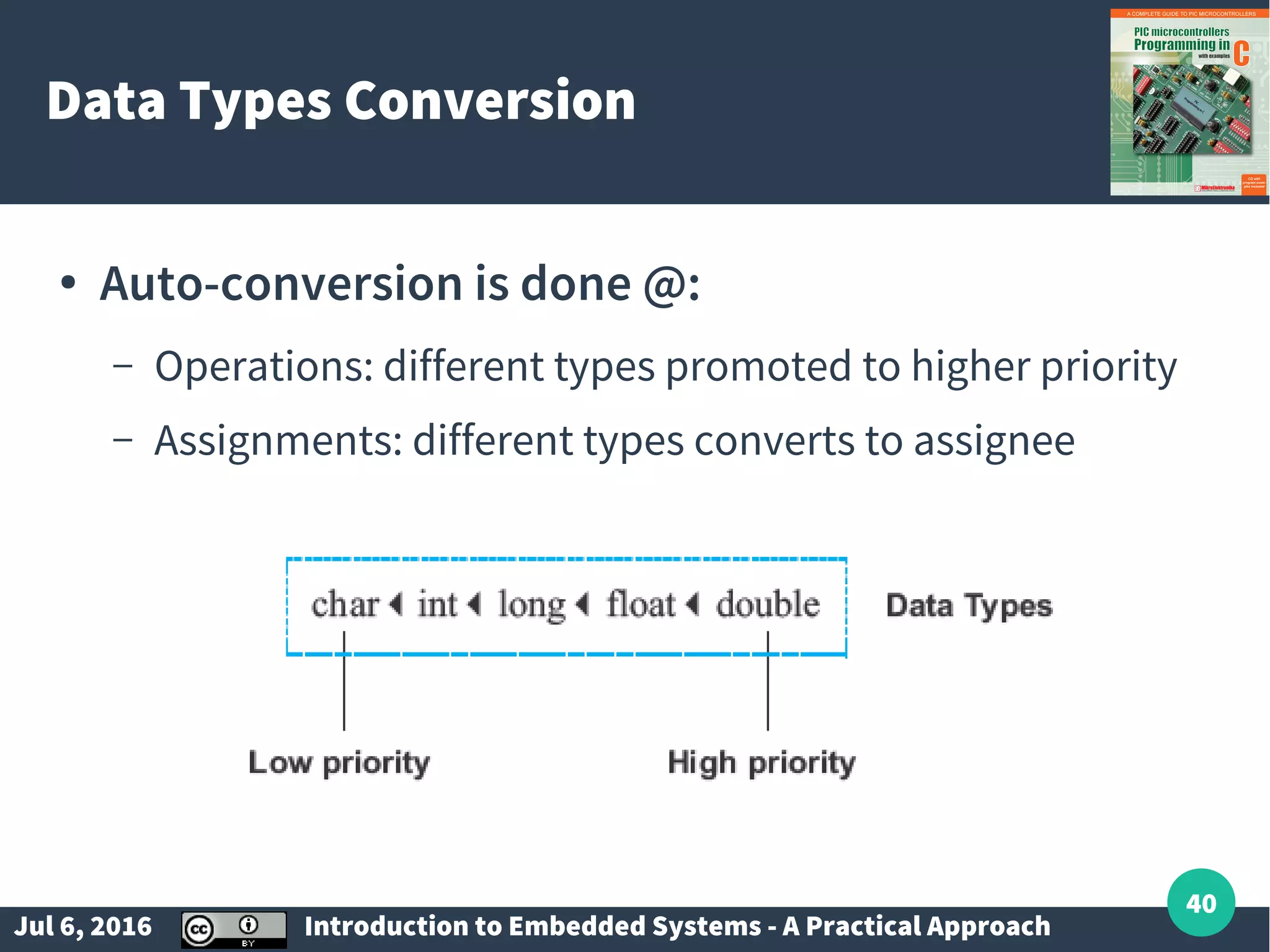
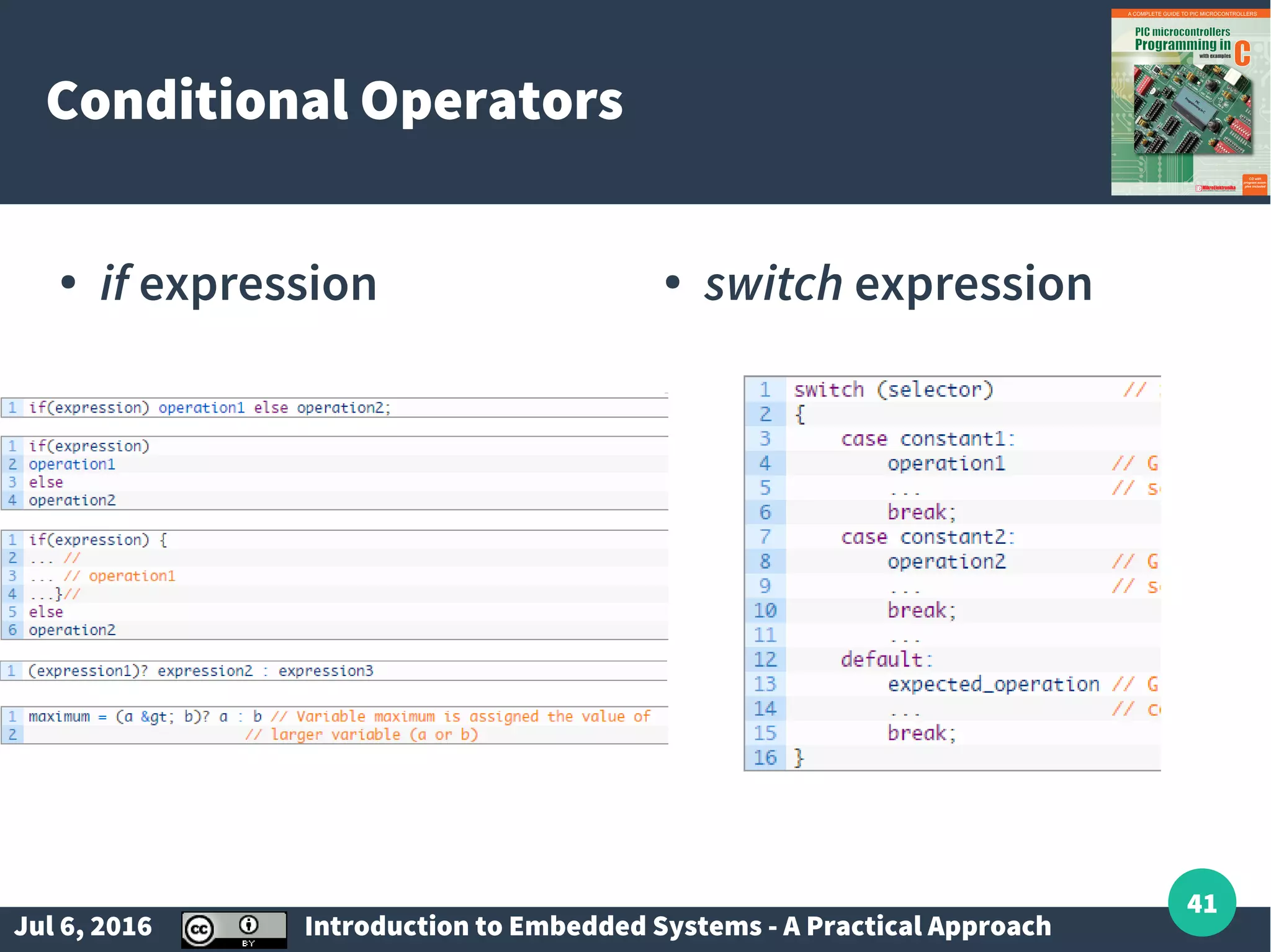
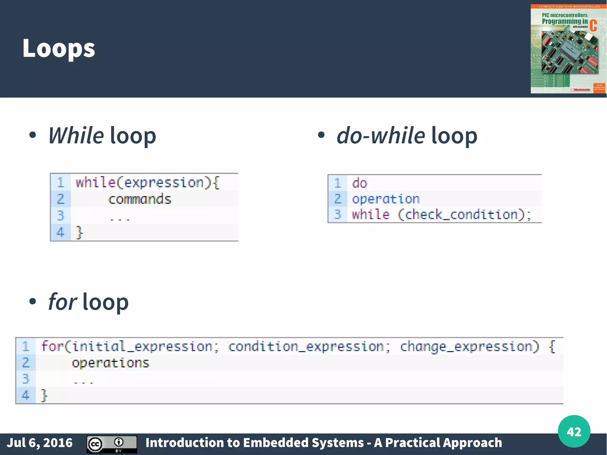
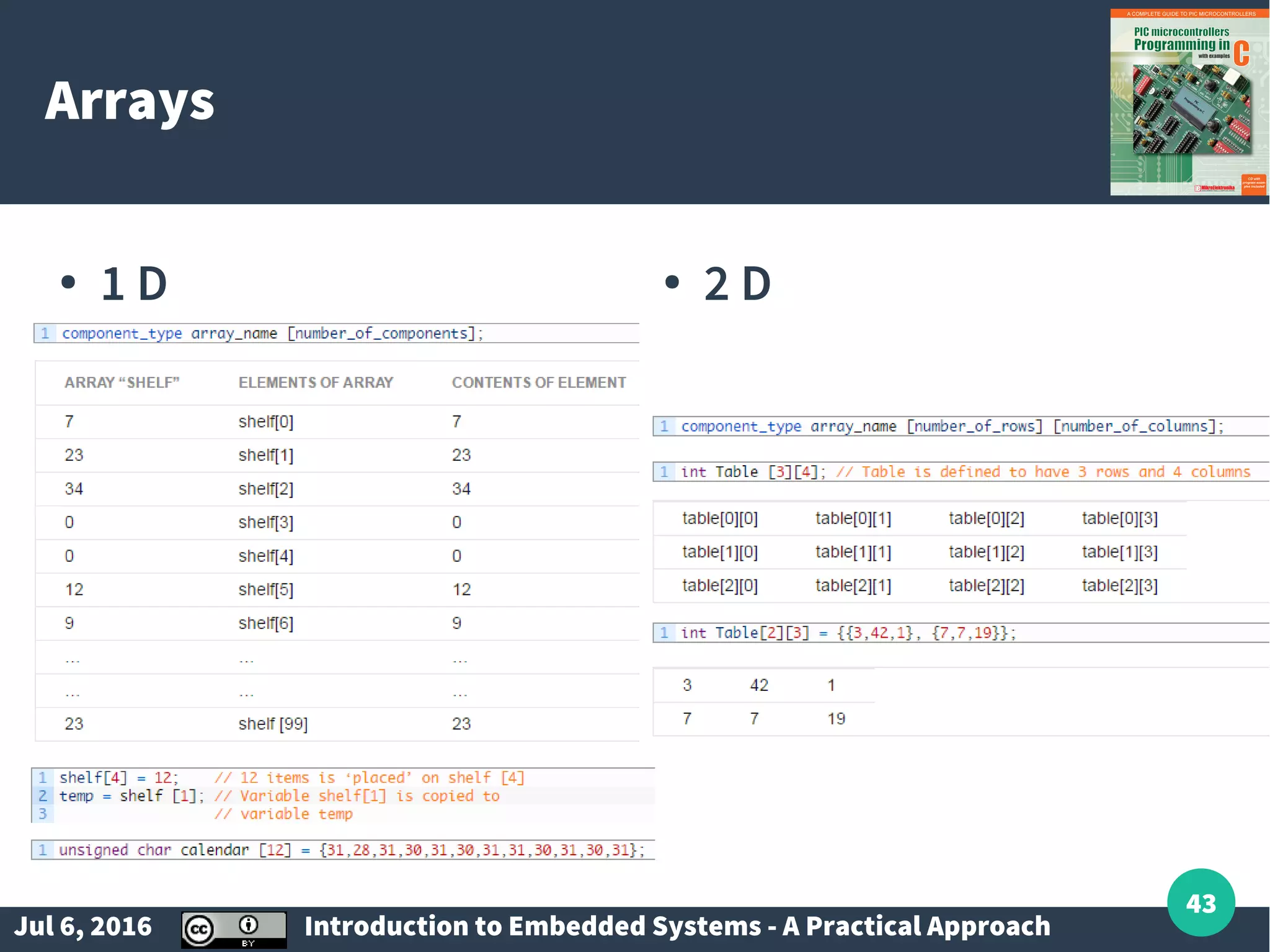
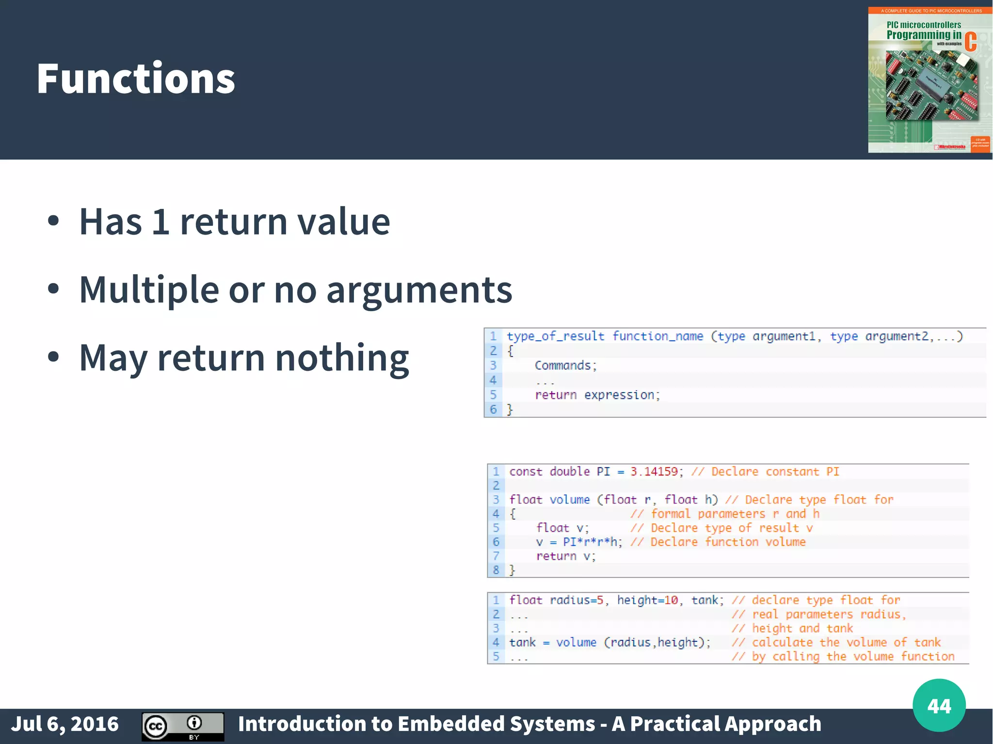
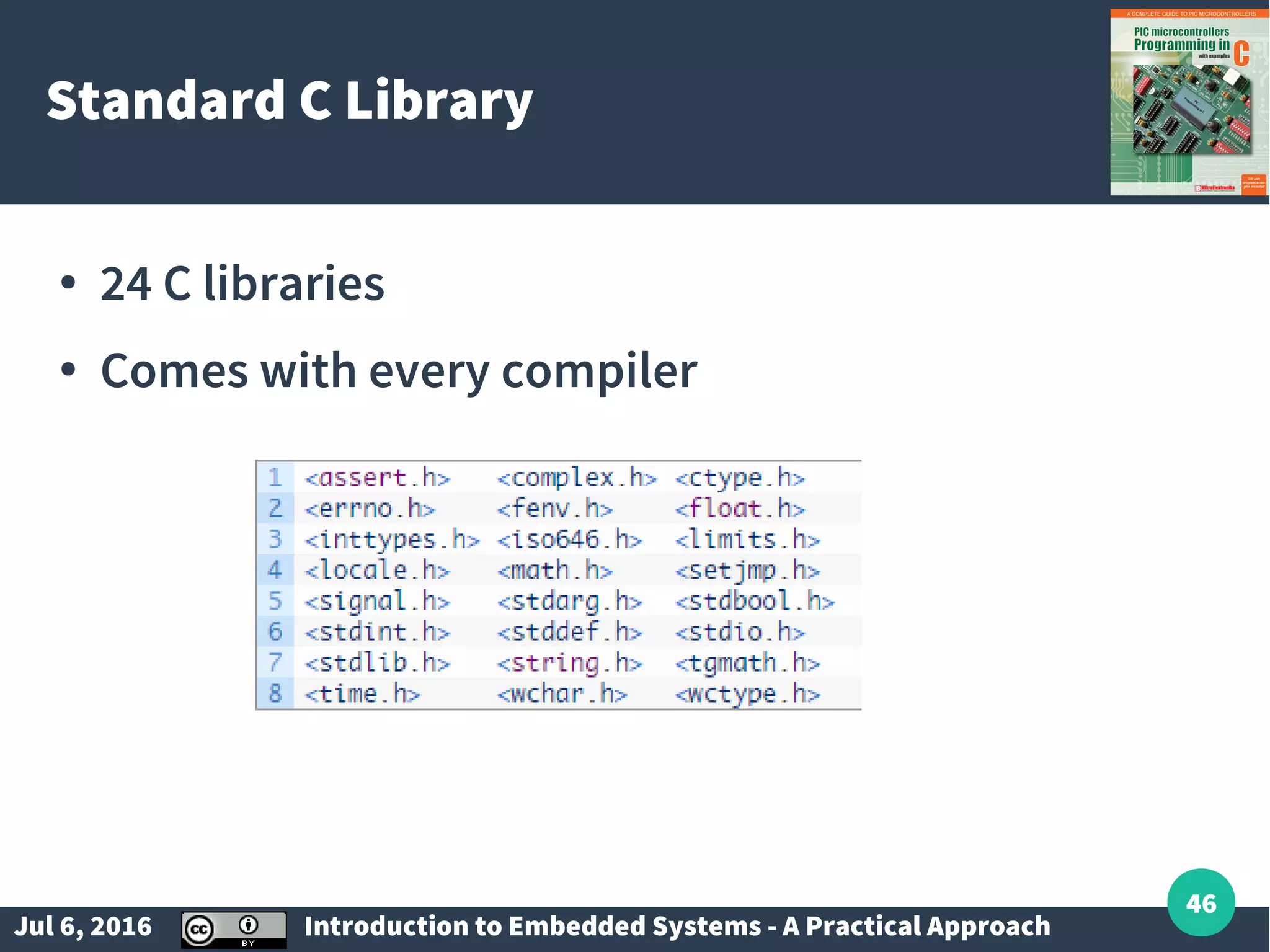
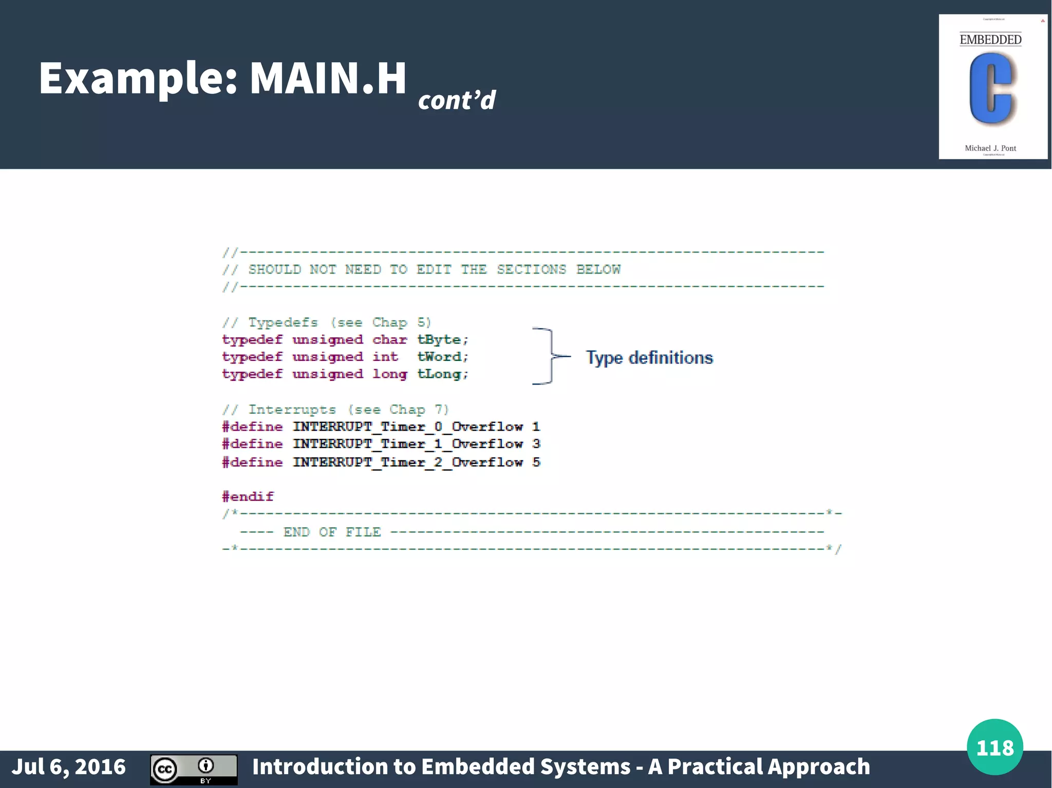
Essentials of programming embedded systems using C, including data types, variables, functions, and libraries.
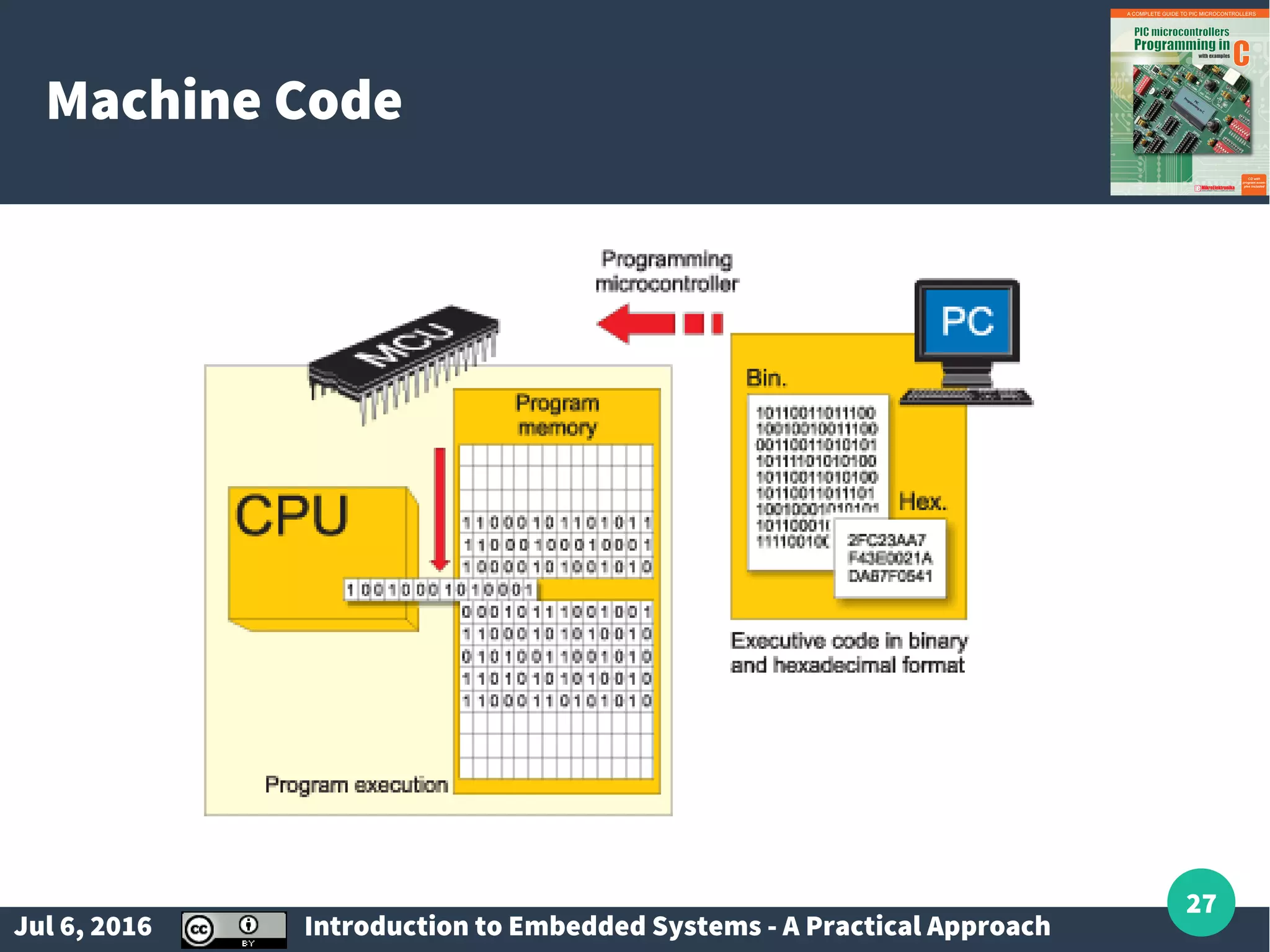
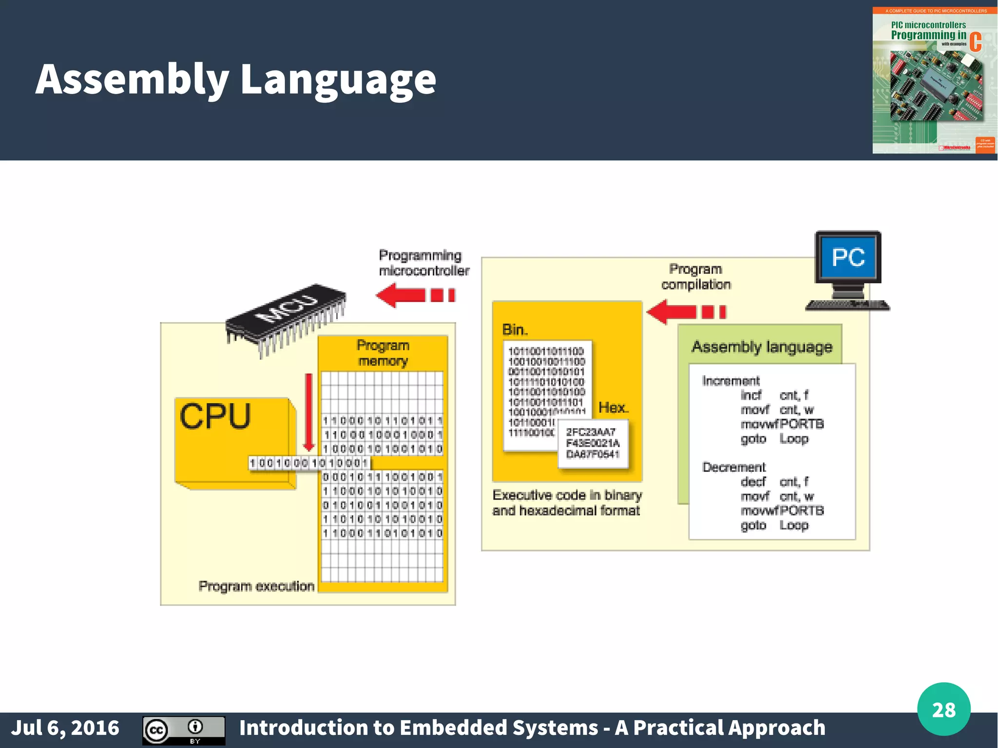
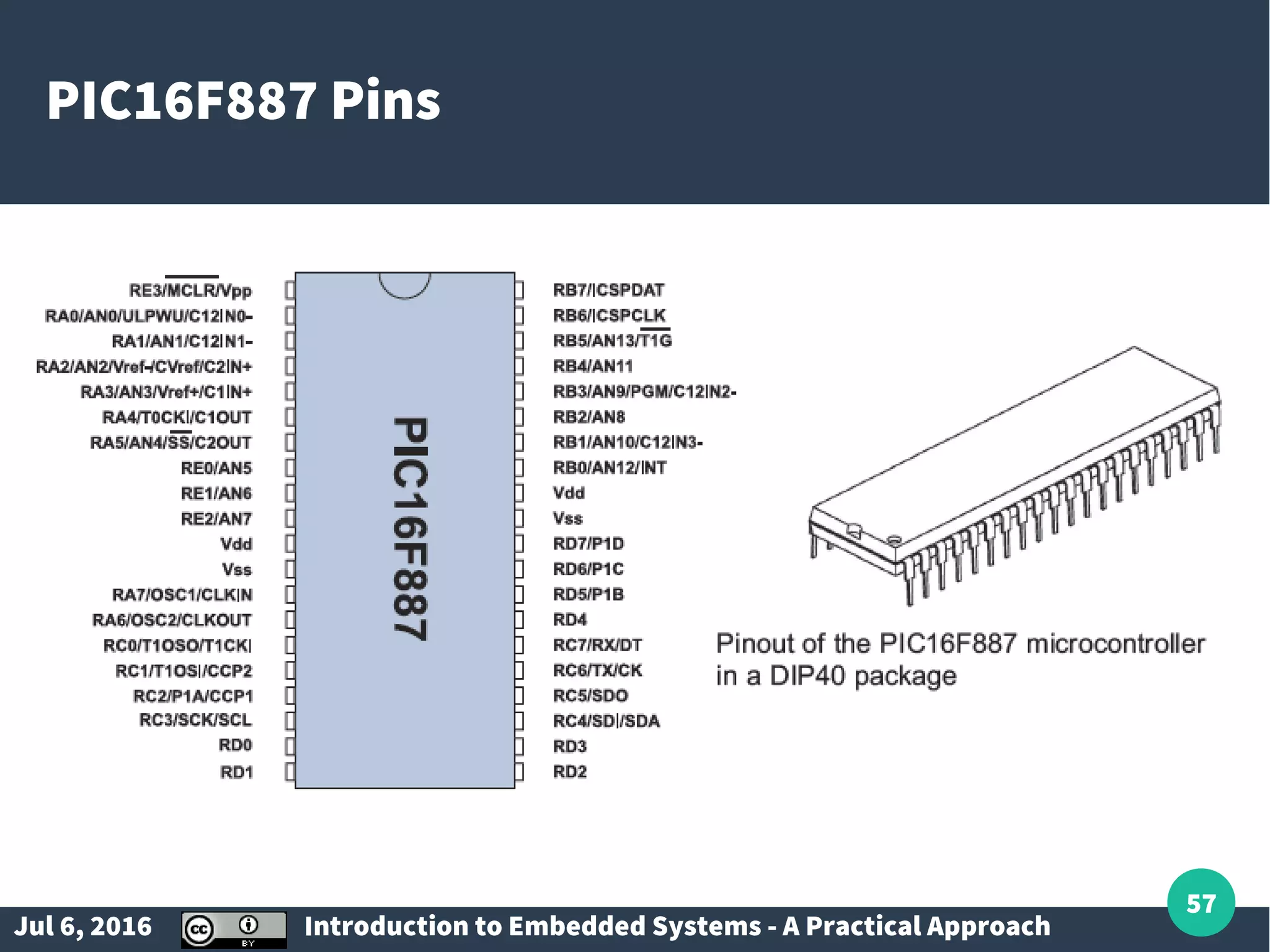
Instructions on programming structure, standard libraries, machine code, assembly, and the PIC16F887 architecture.
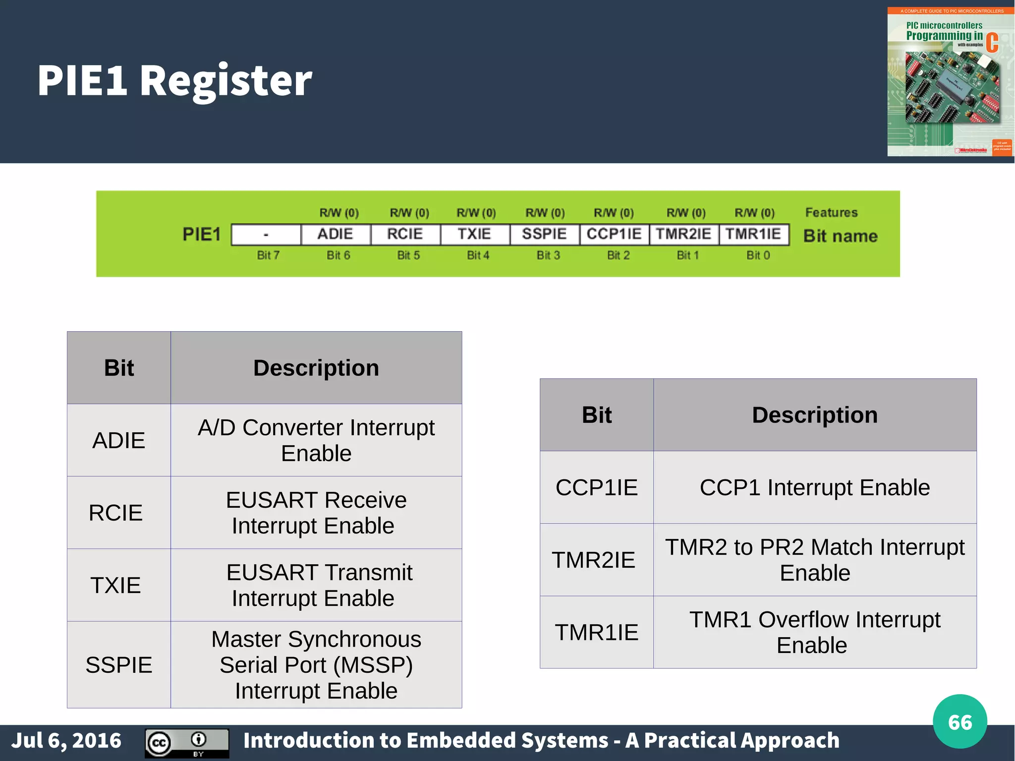
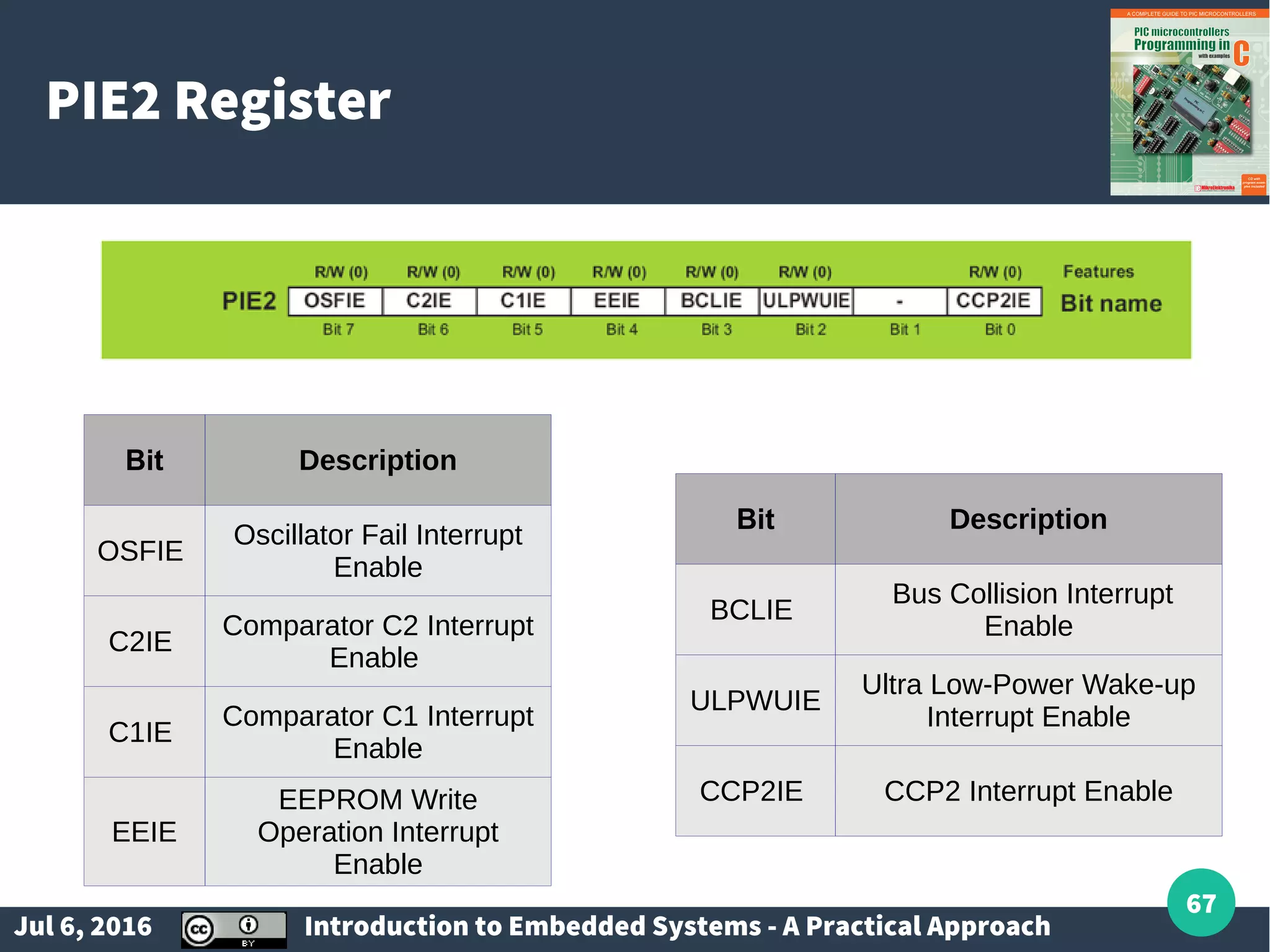
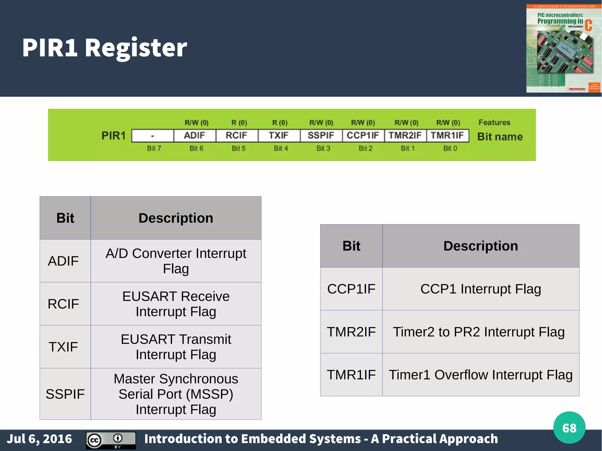
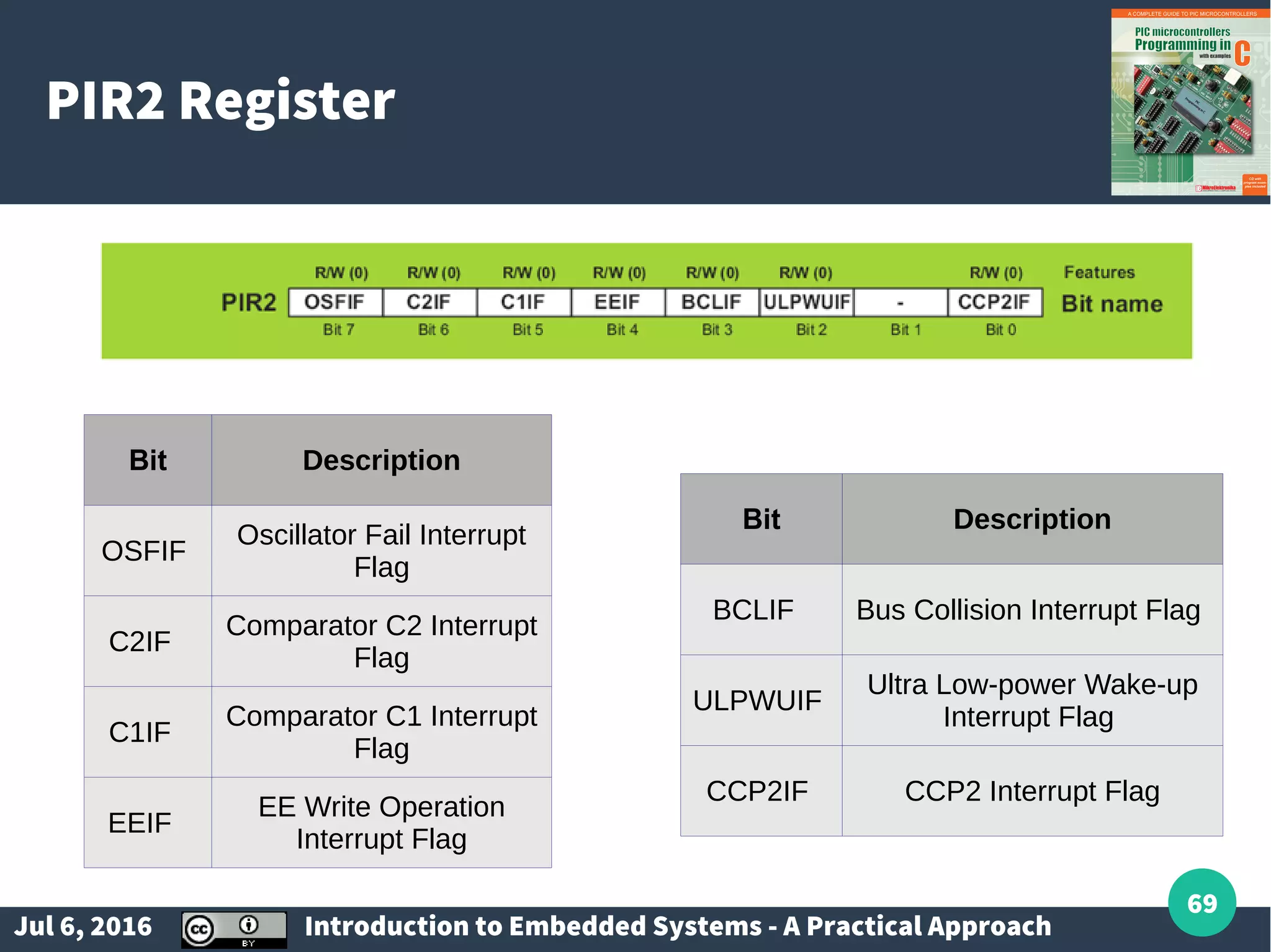
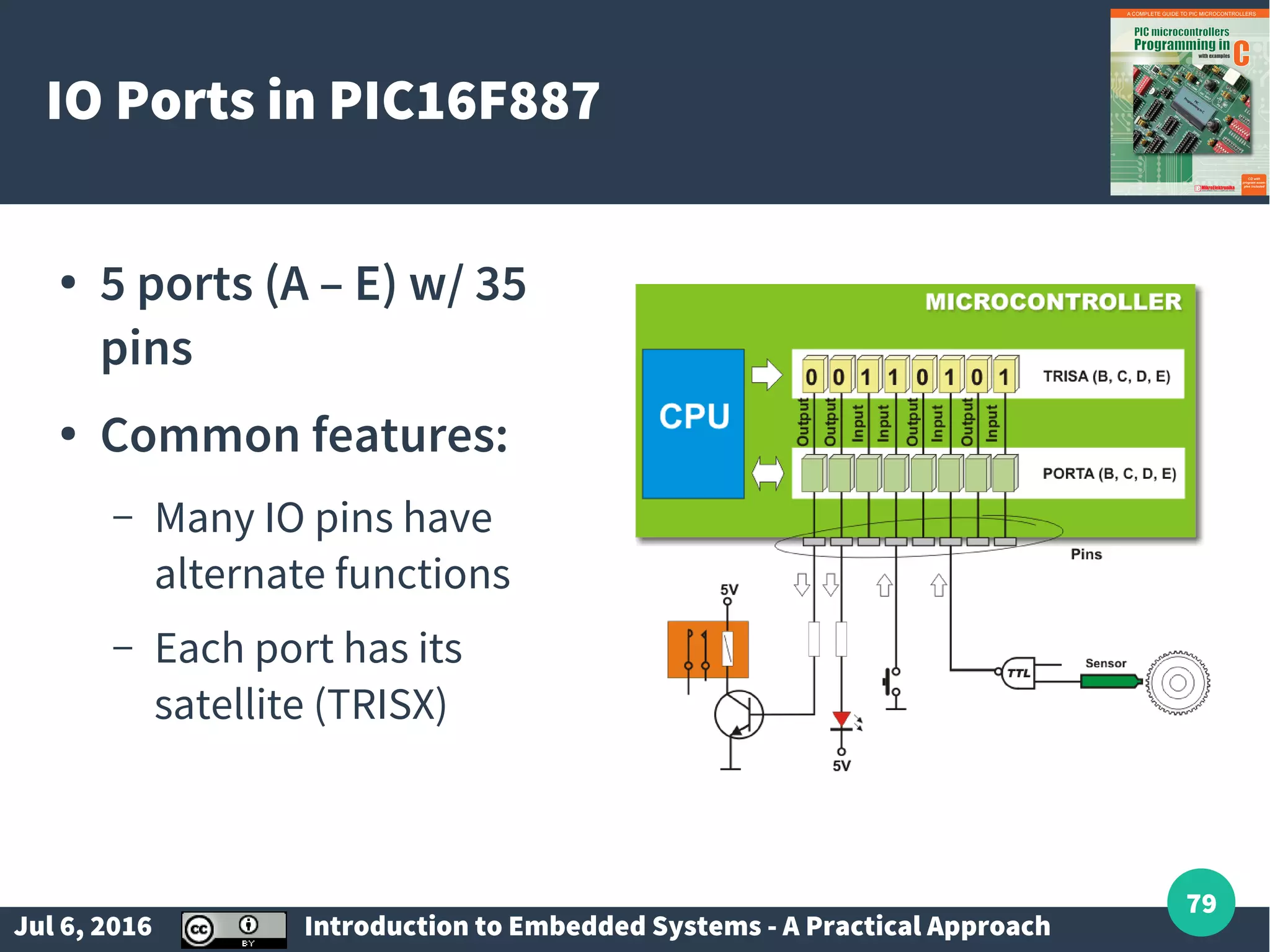
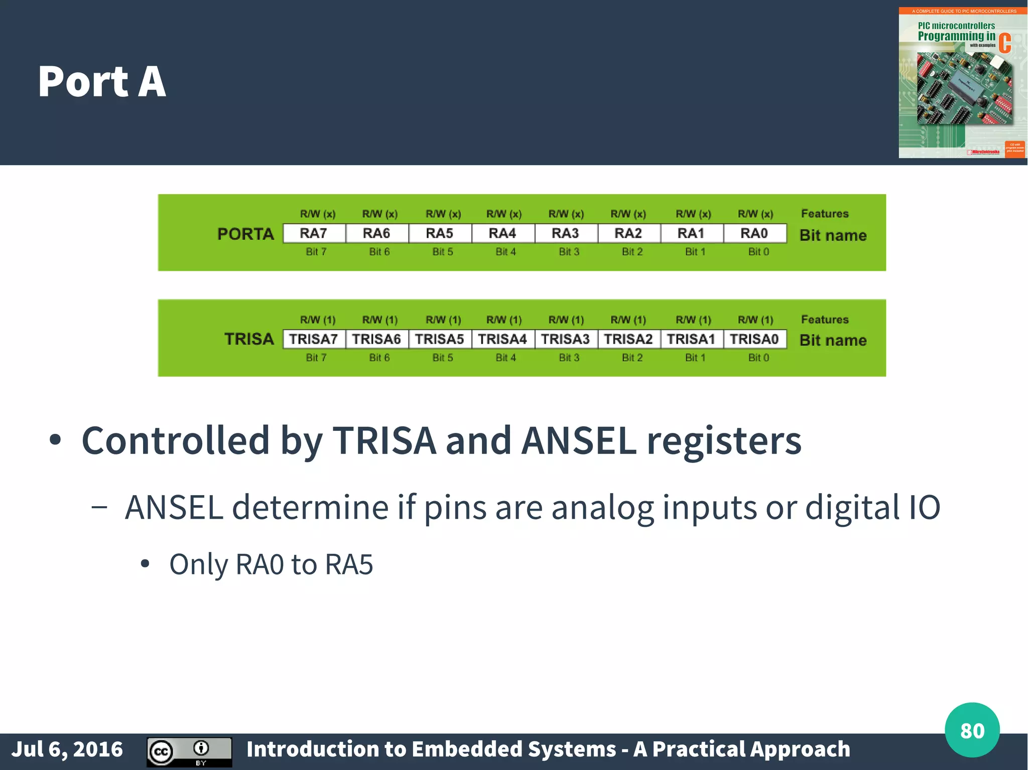
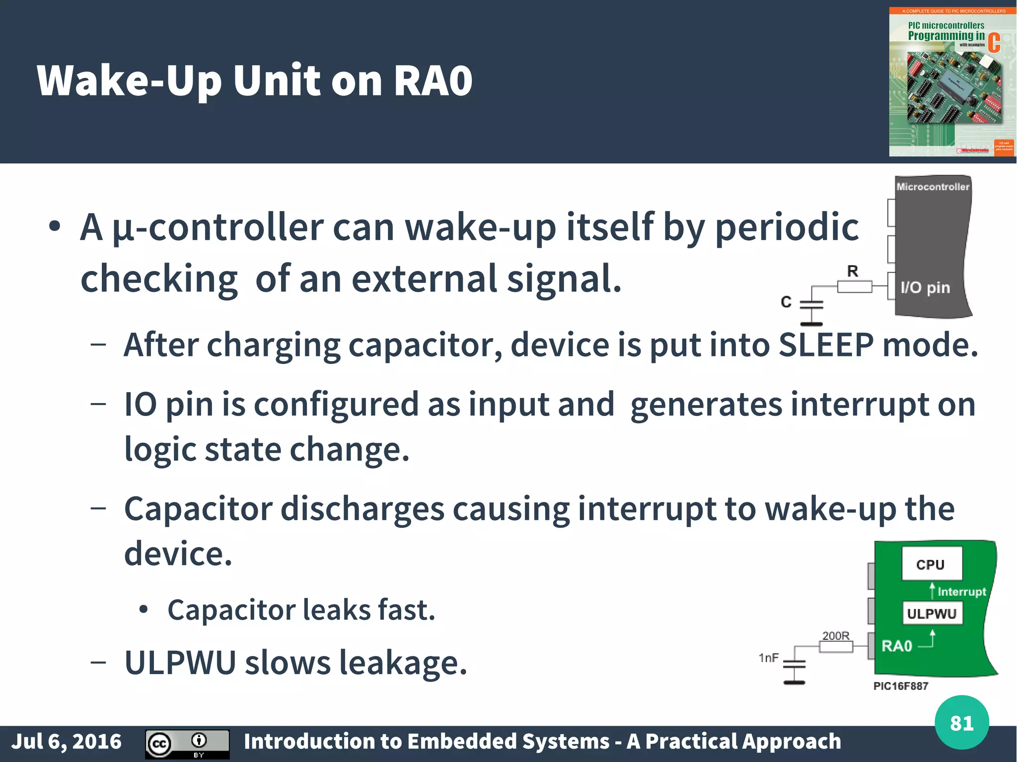
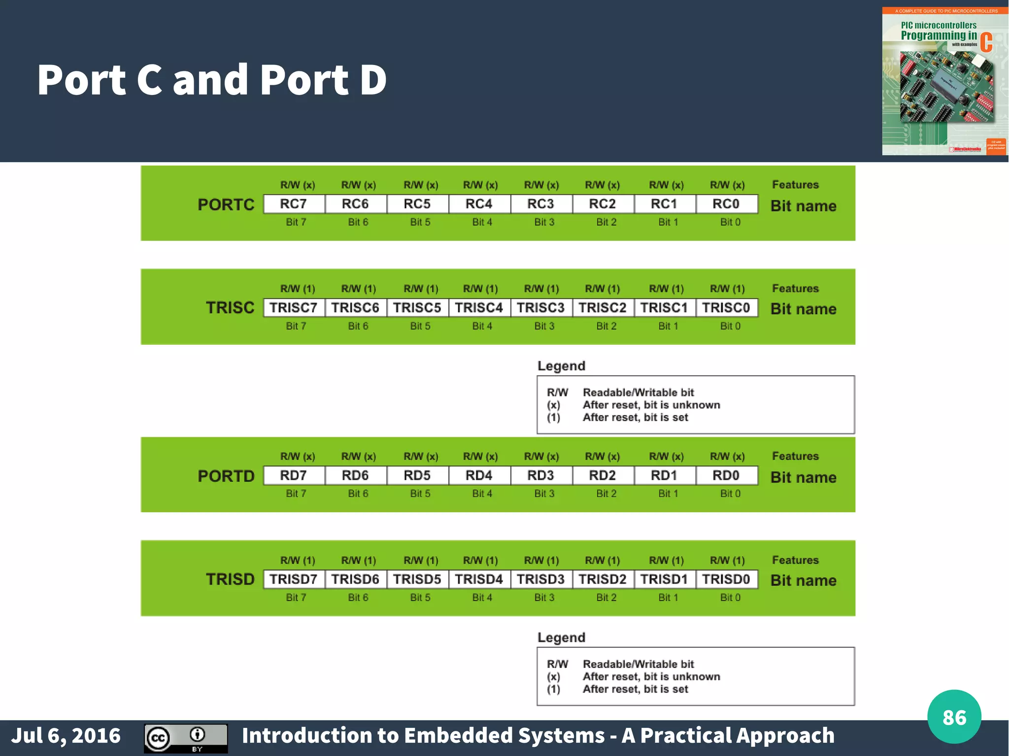
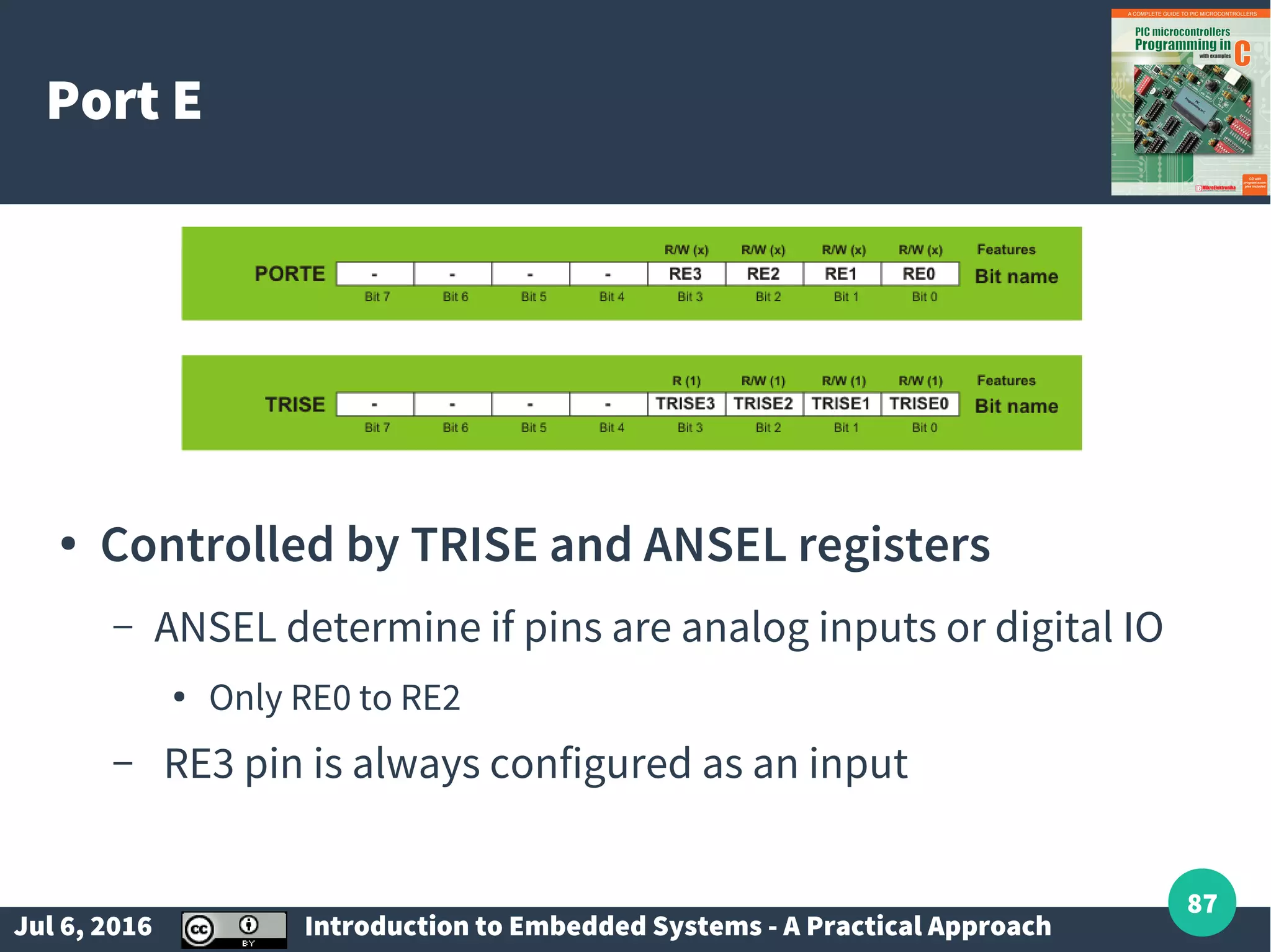
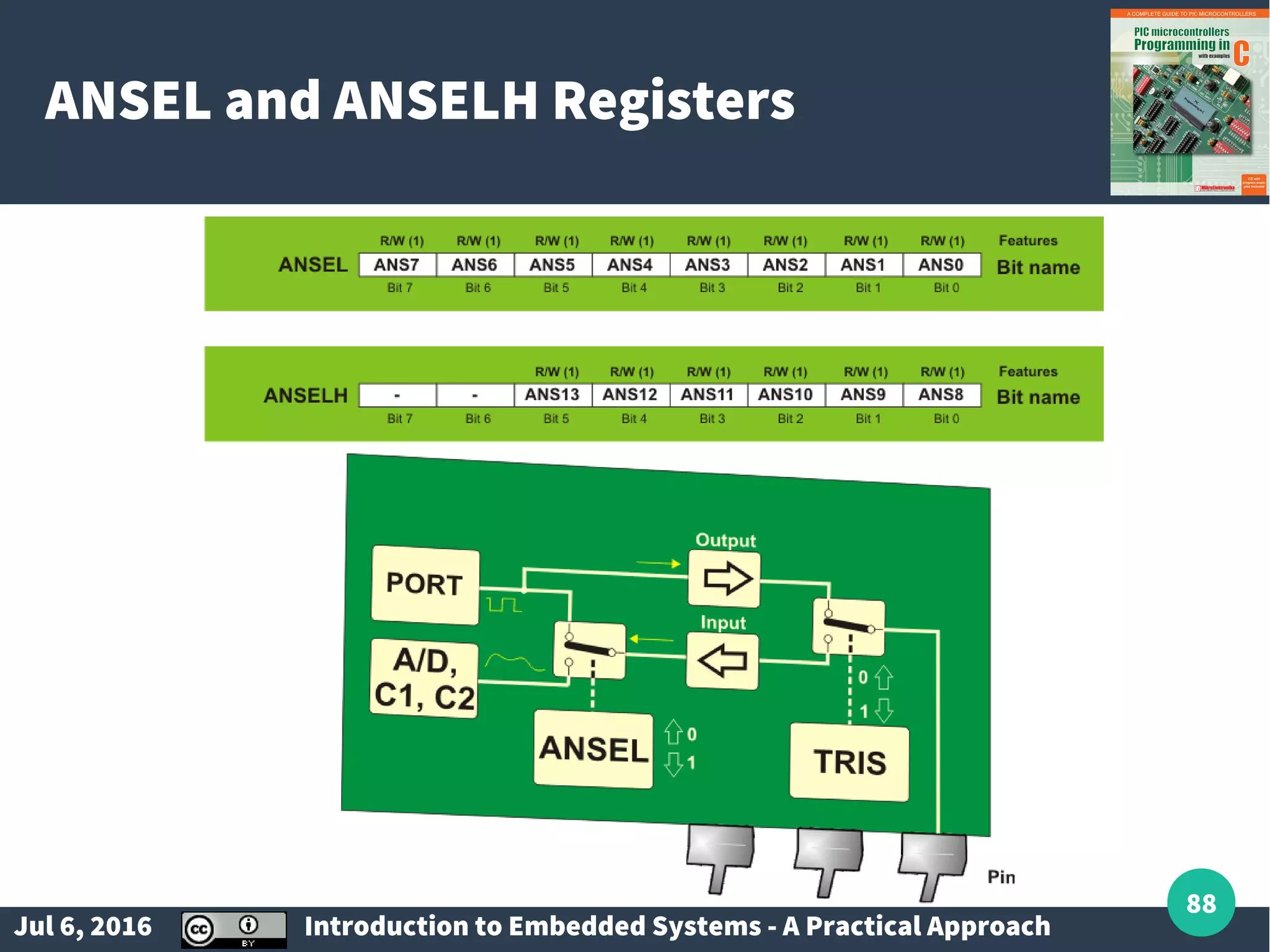
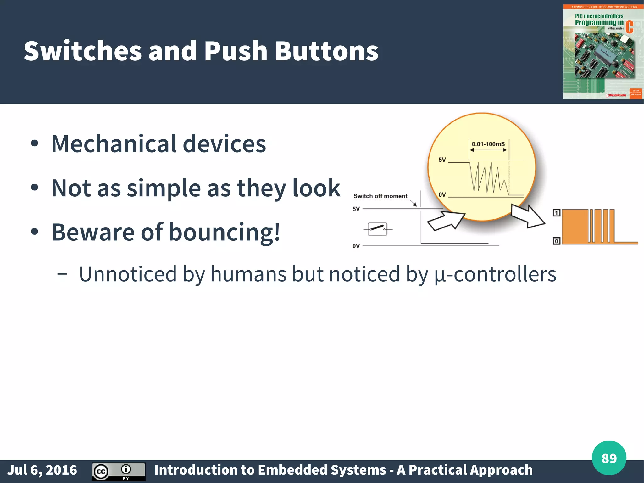
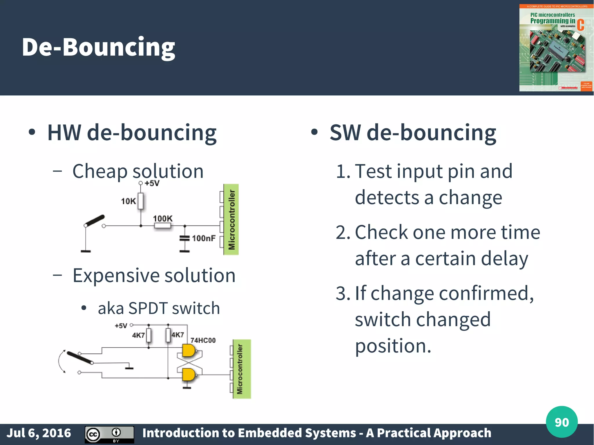
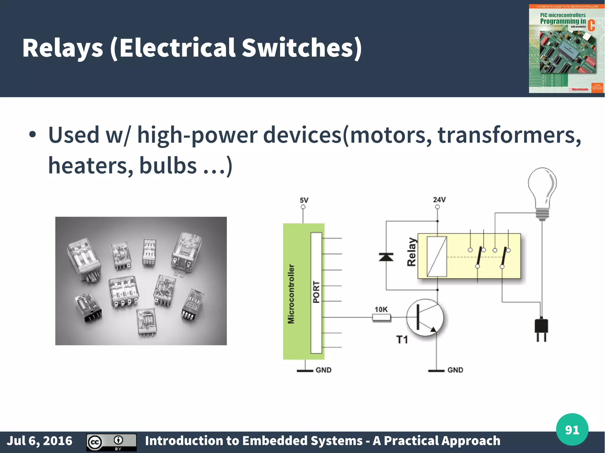
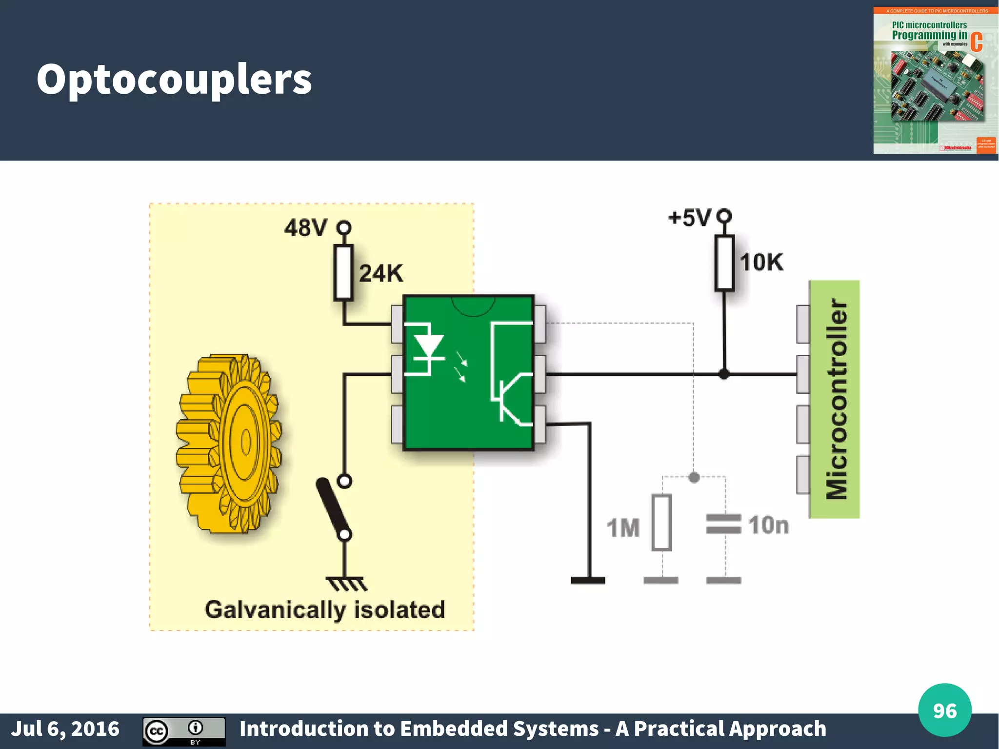
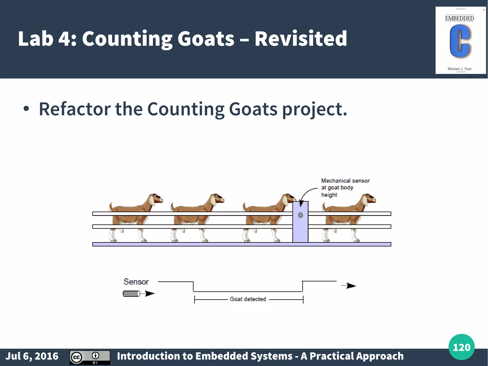
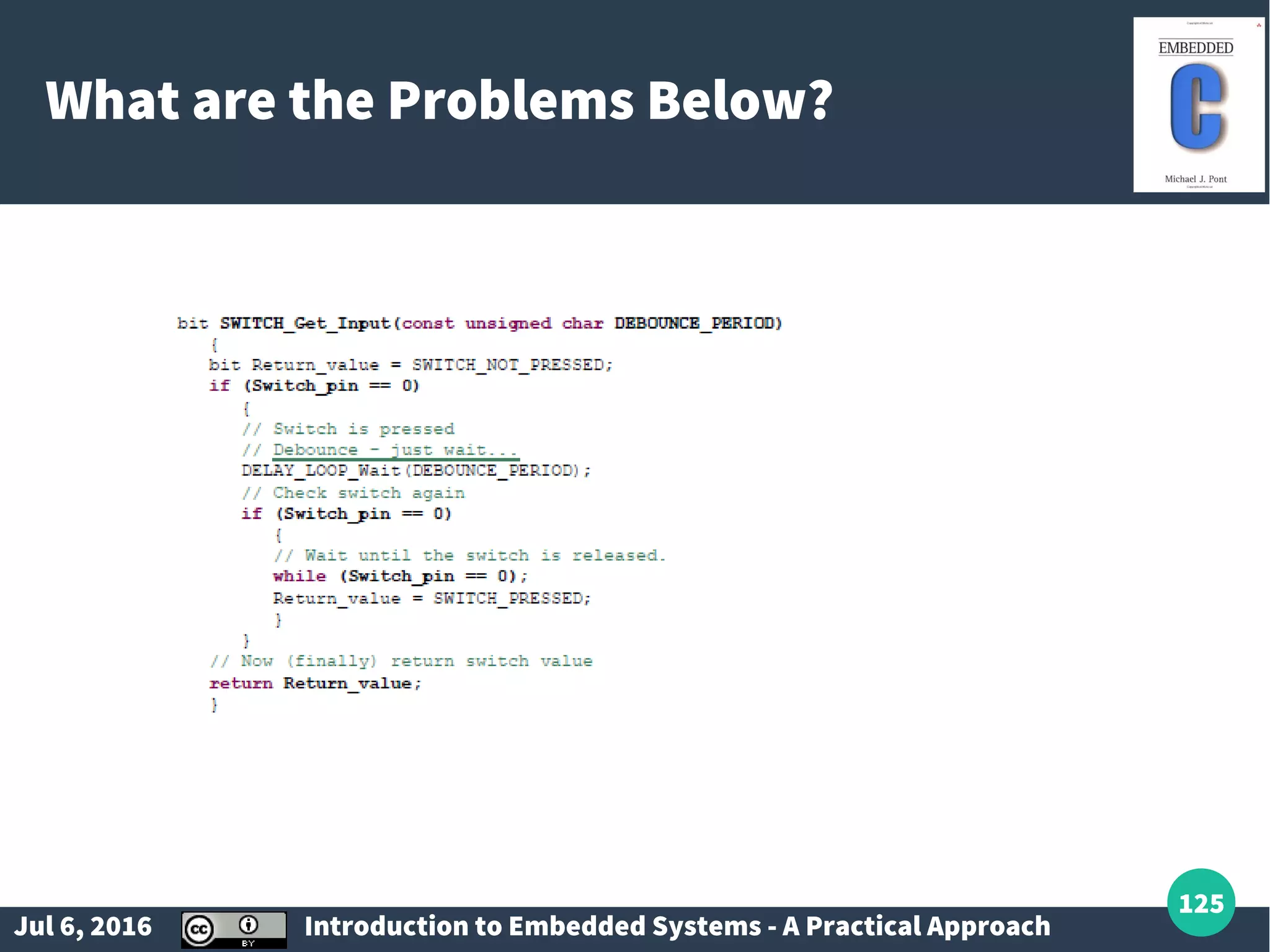
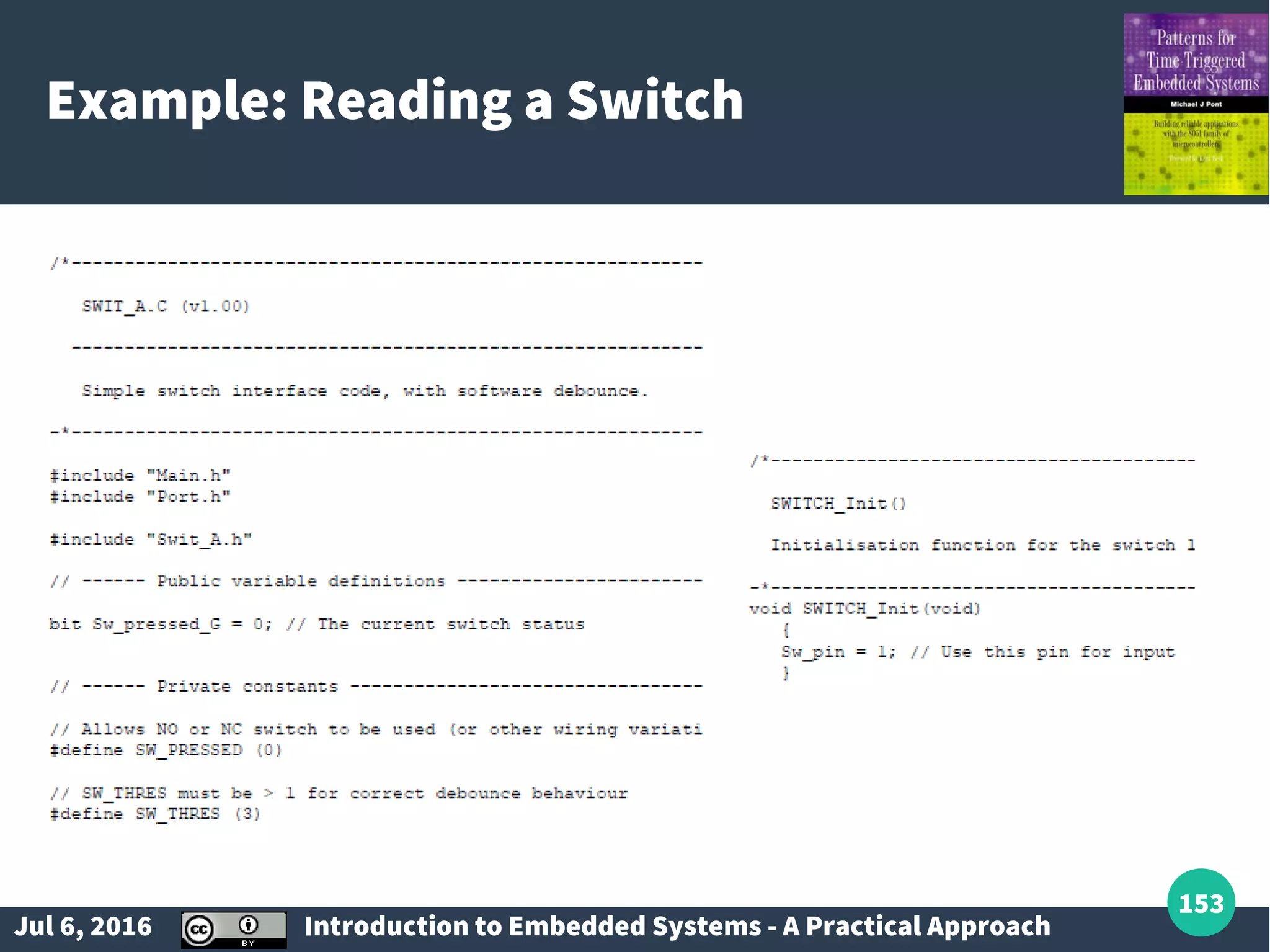
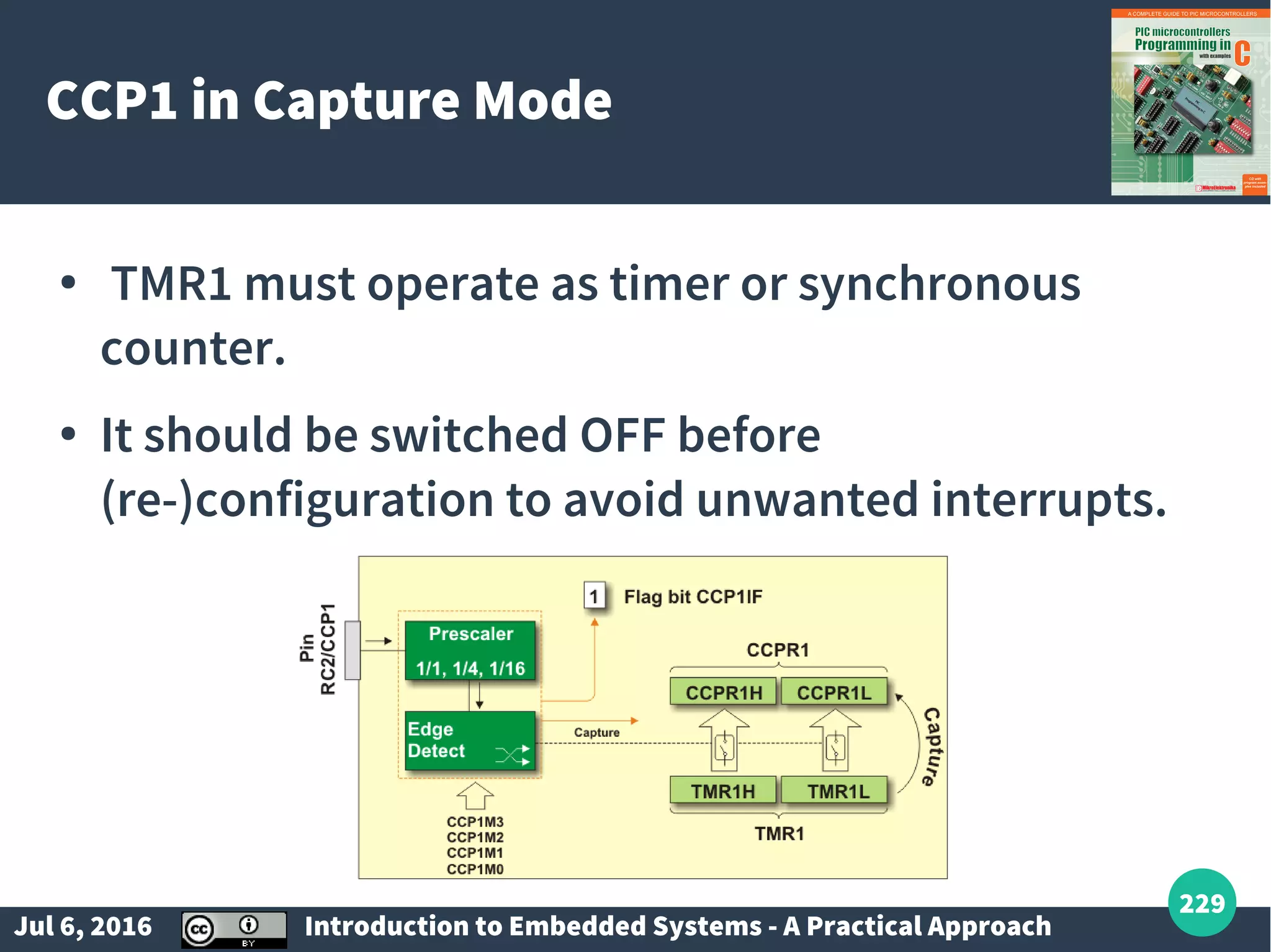
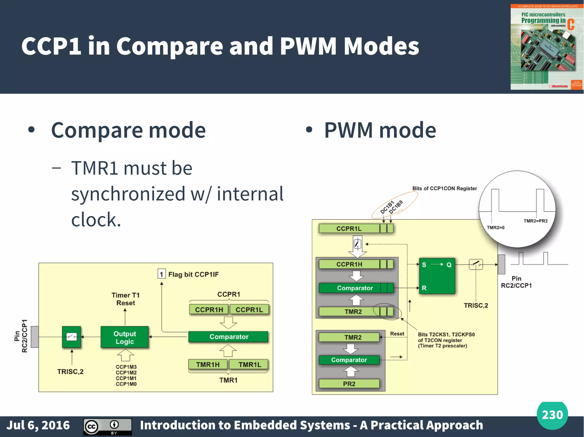
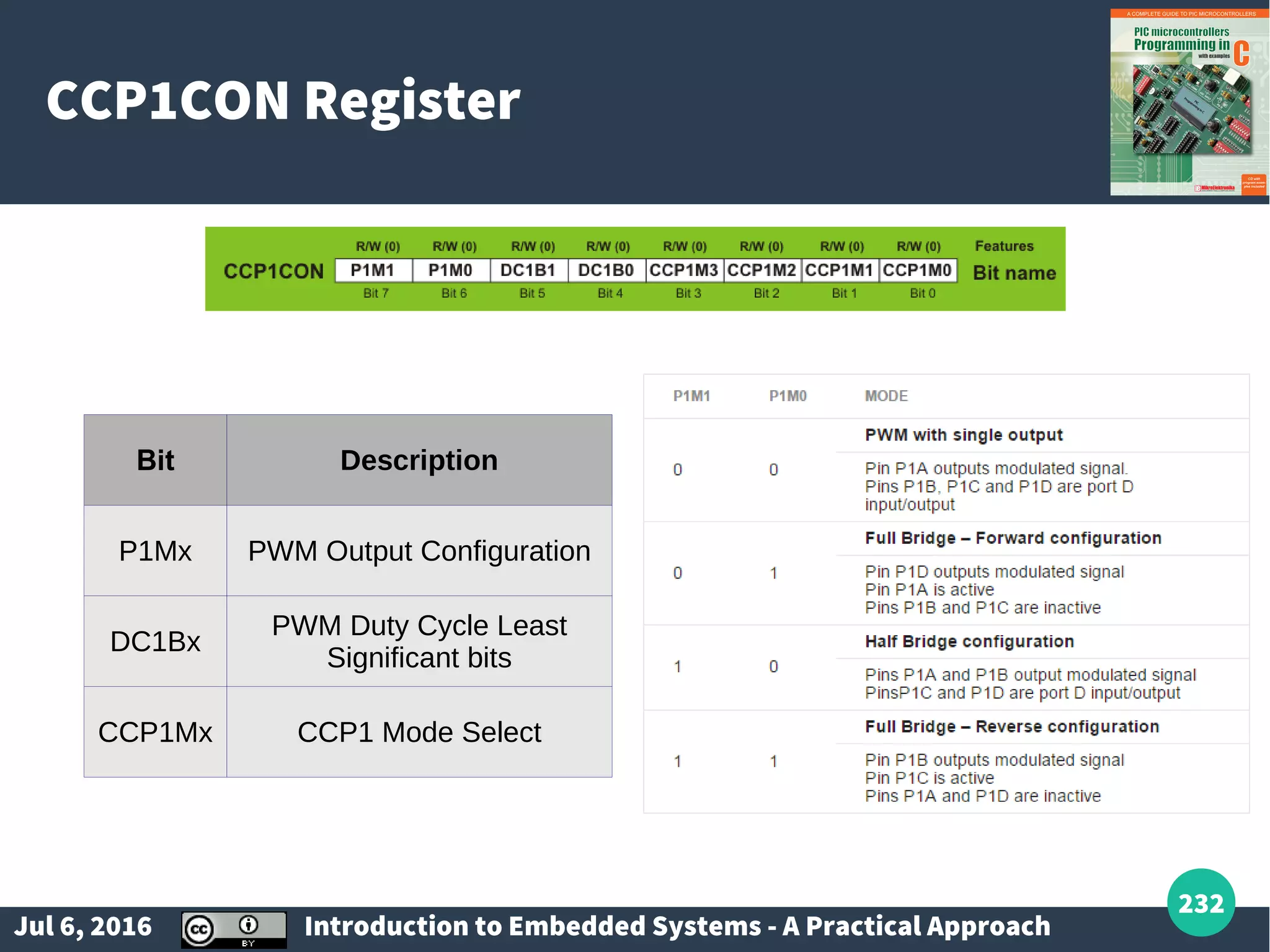
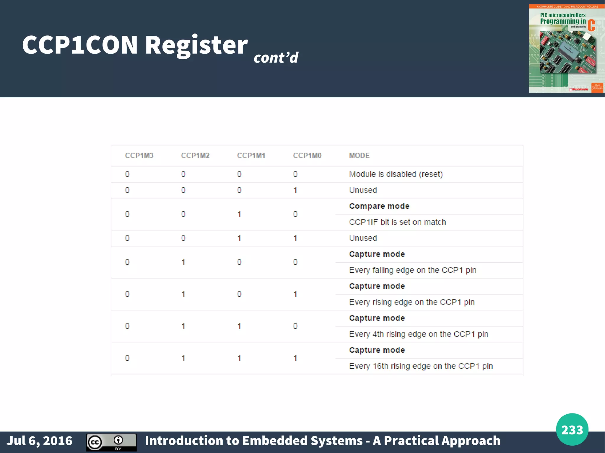
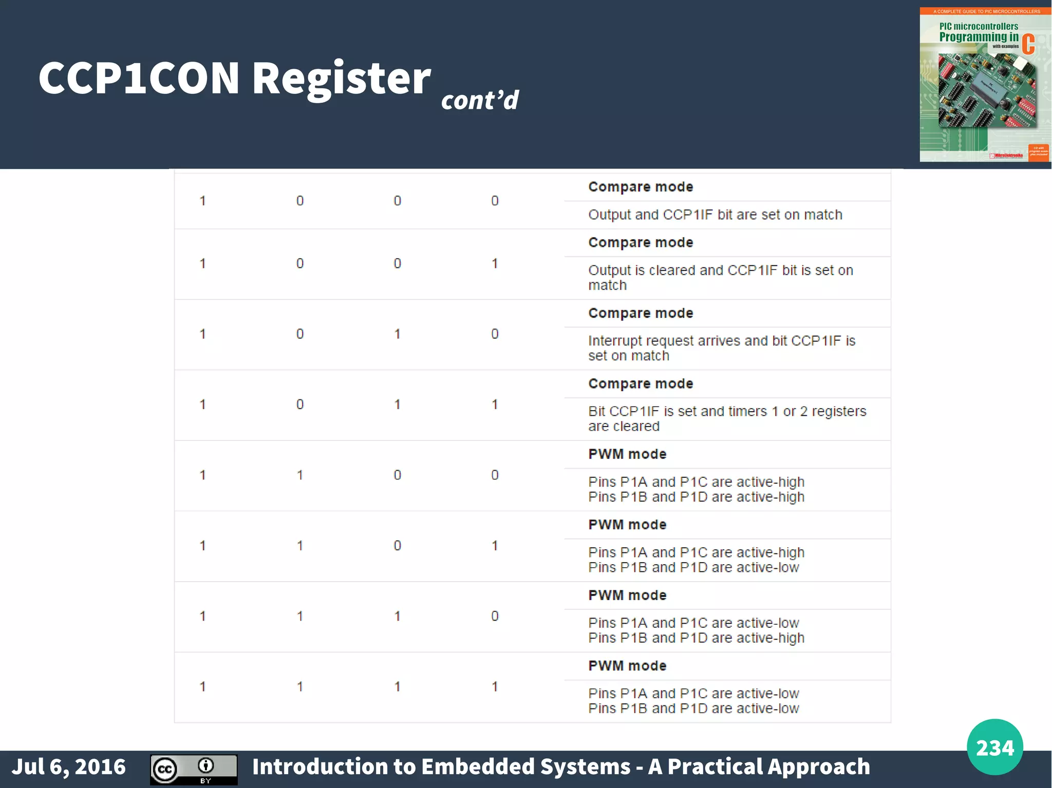
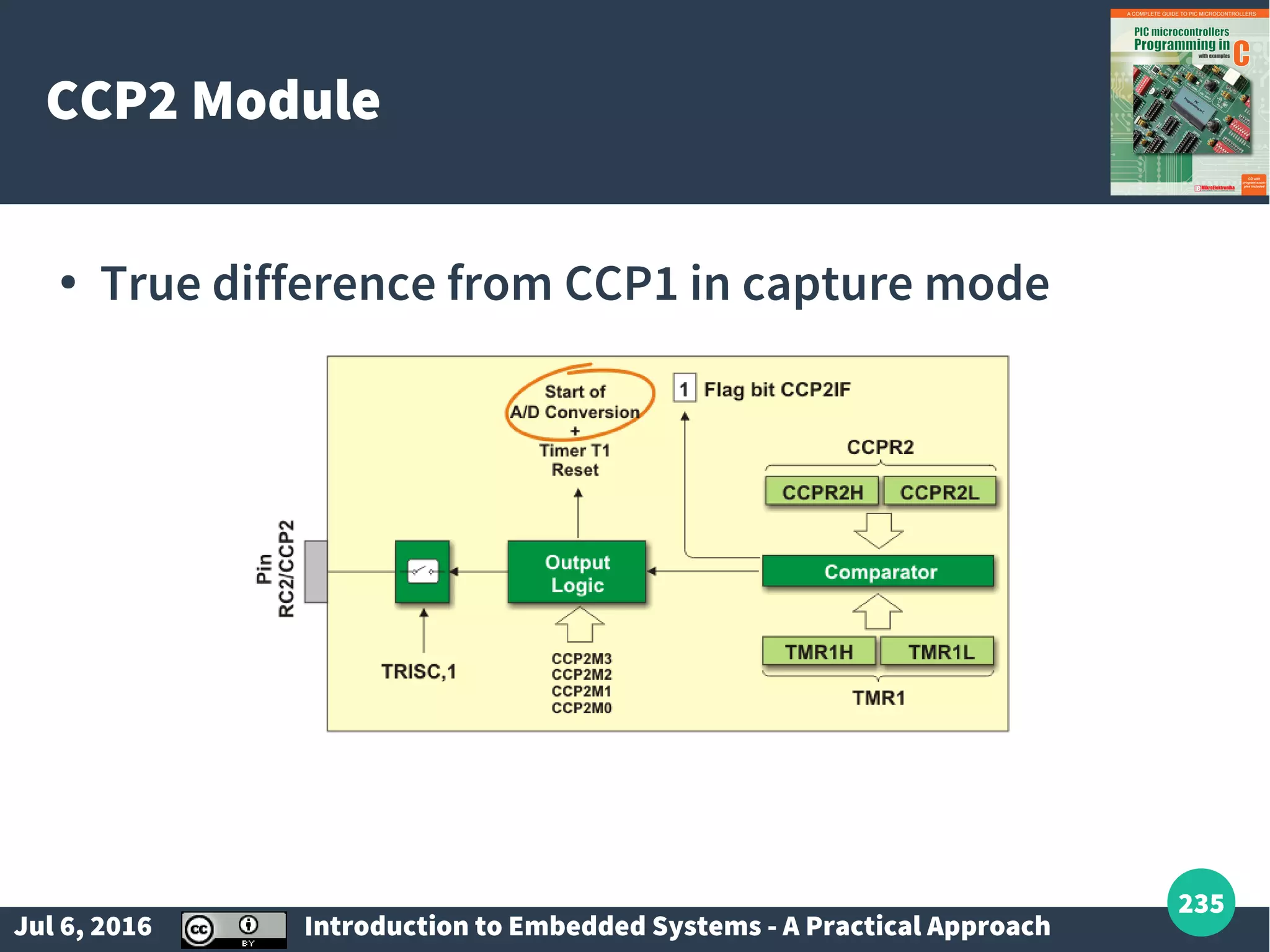
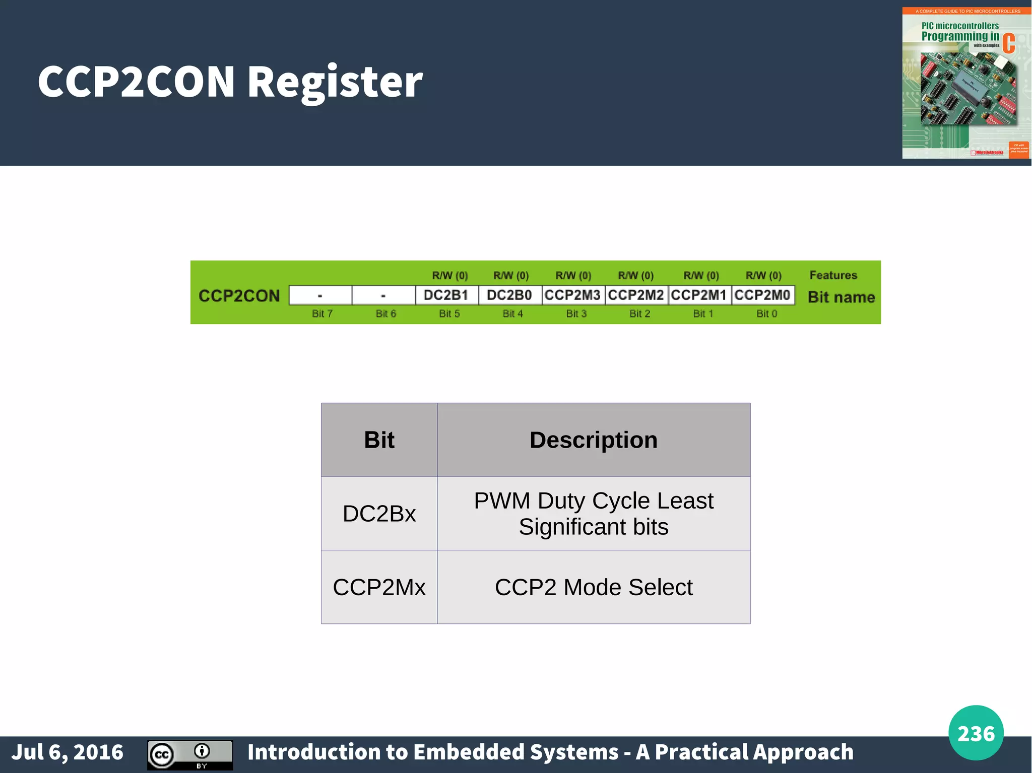
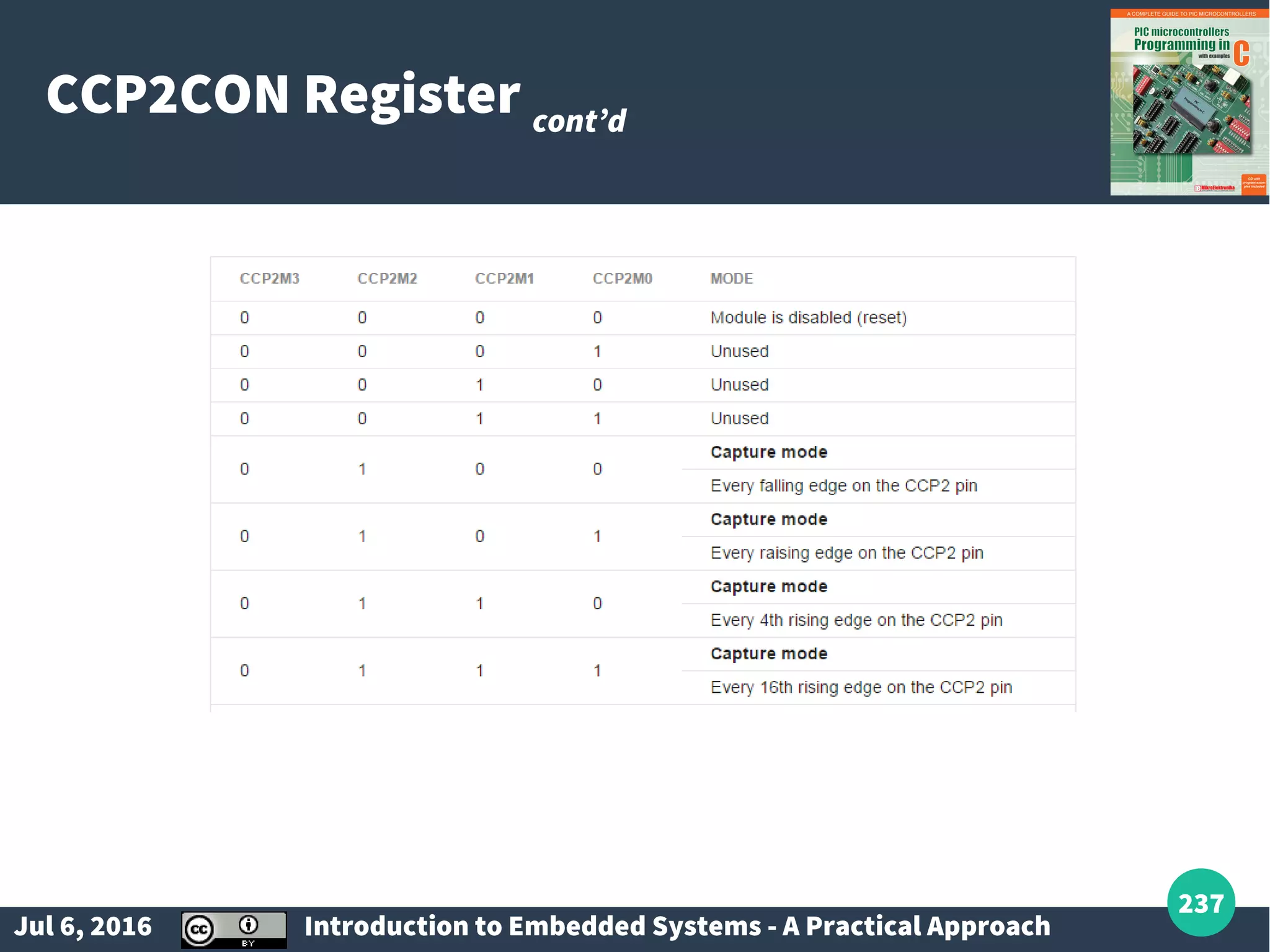
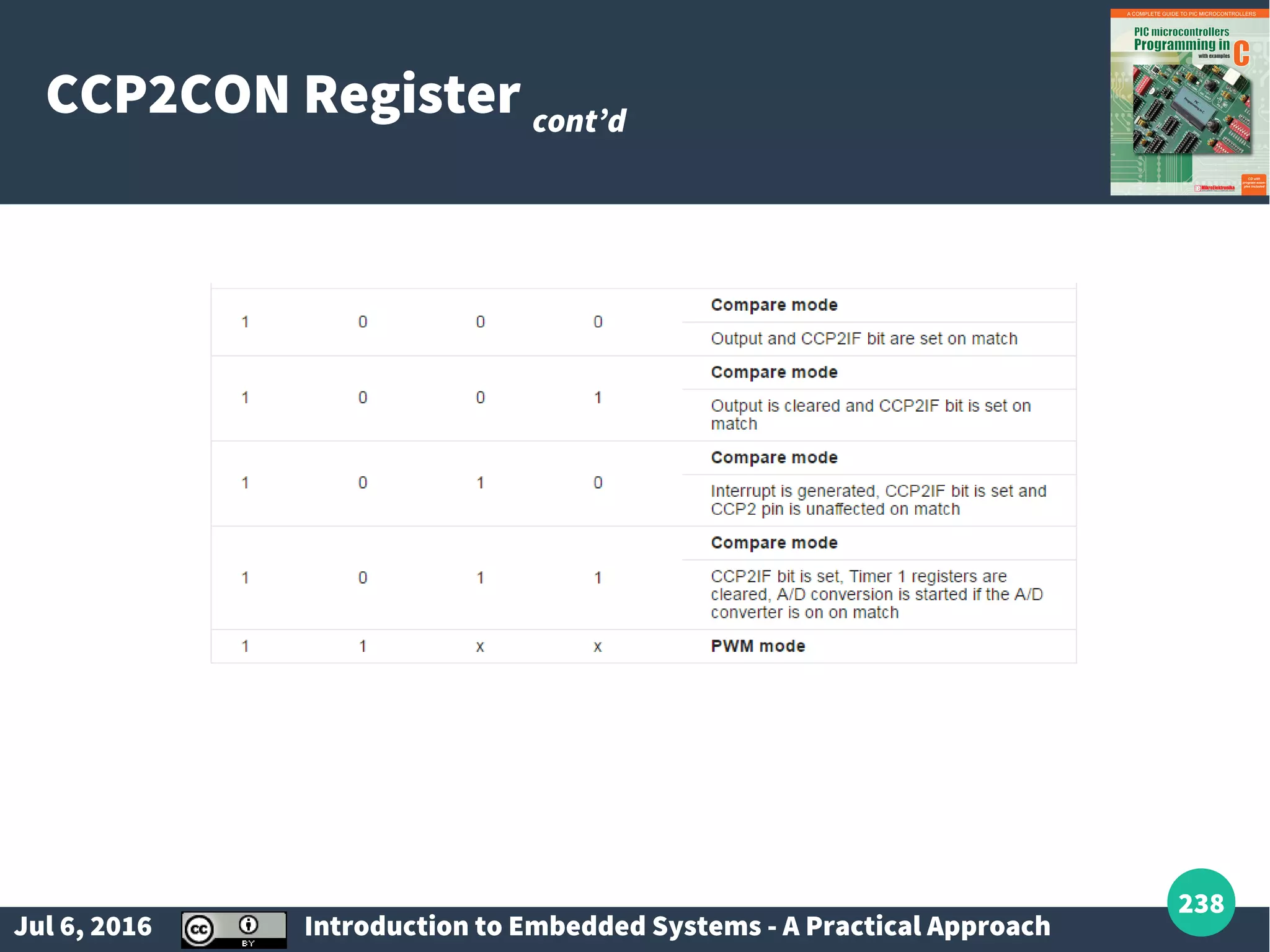
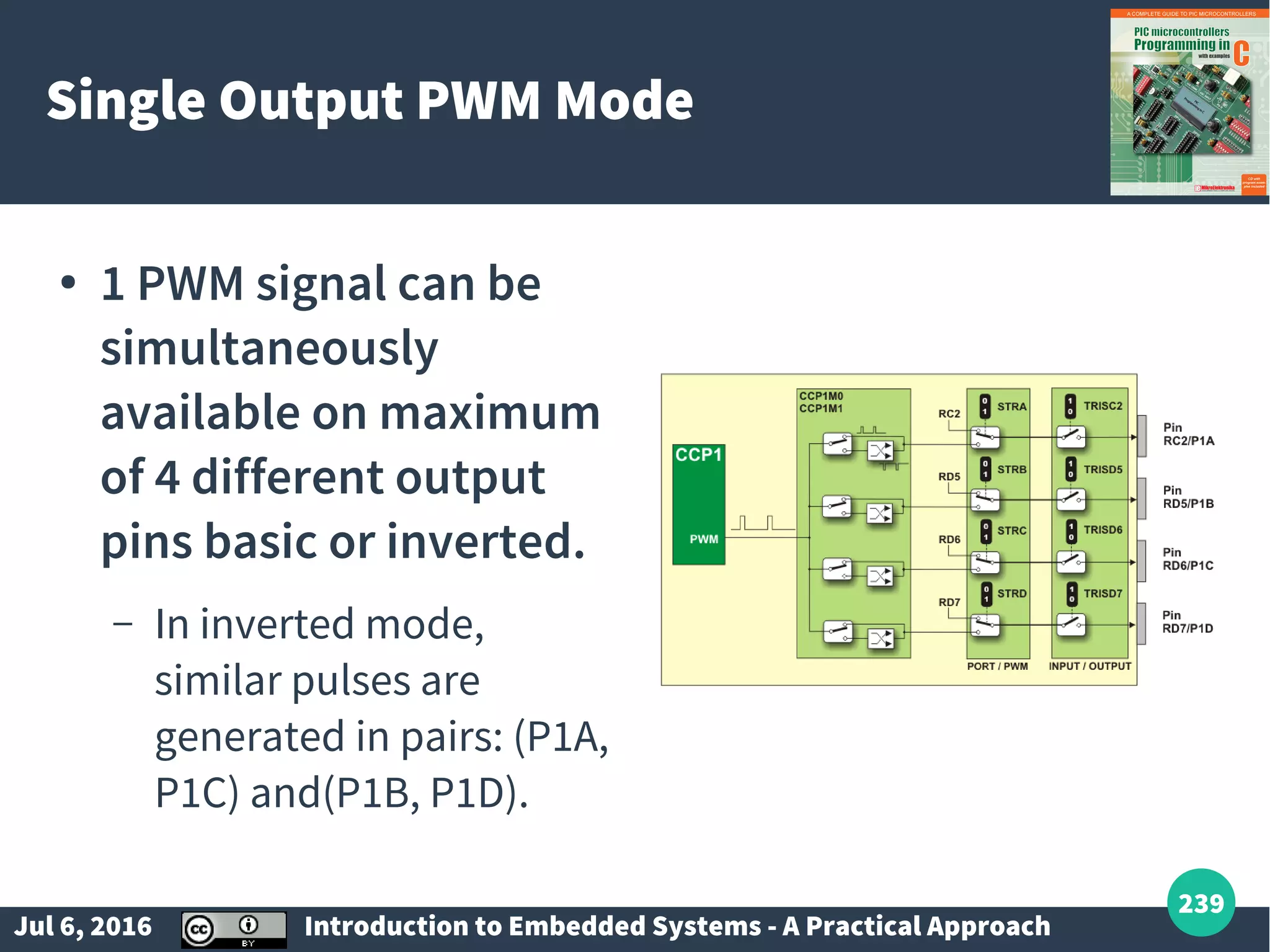
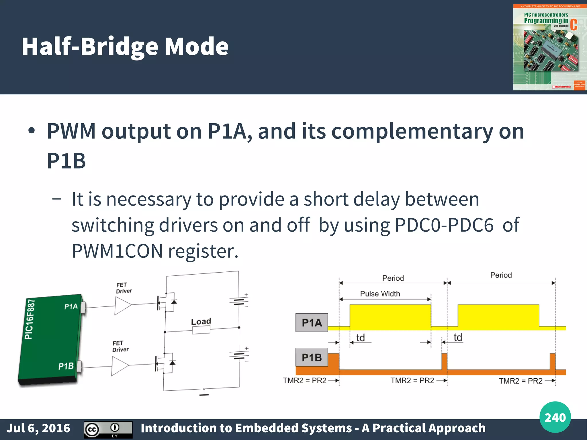
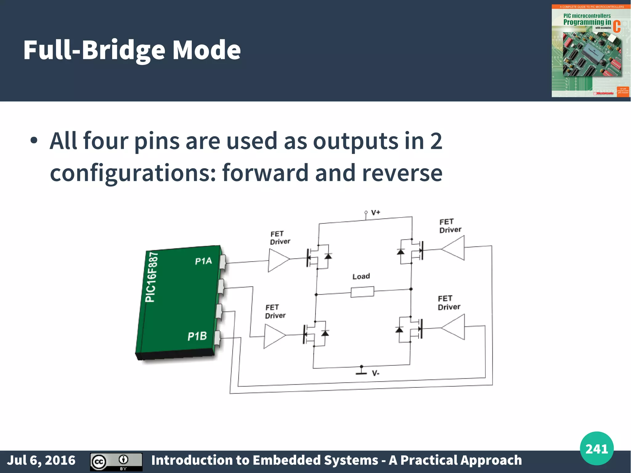
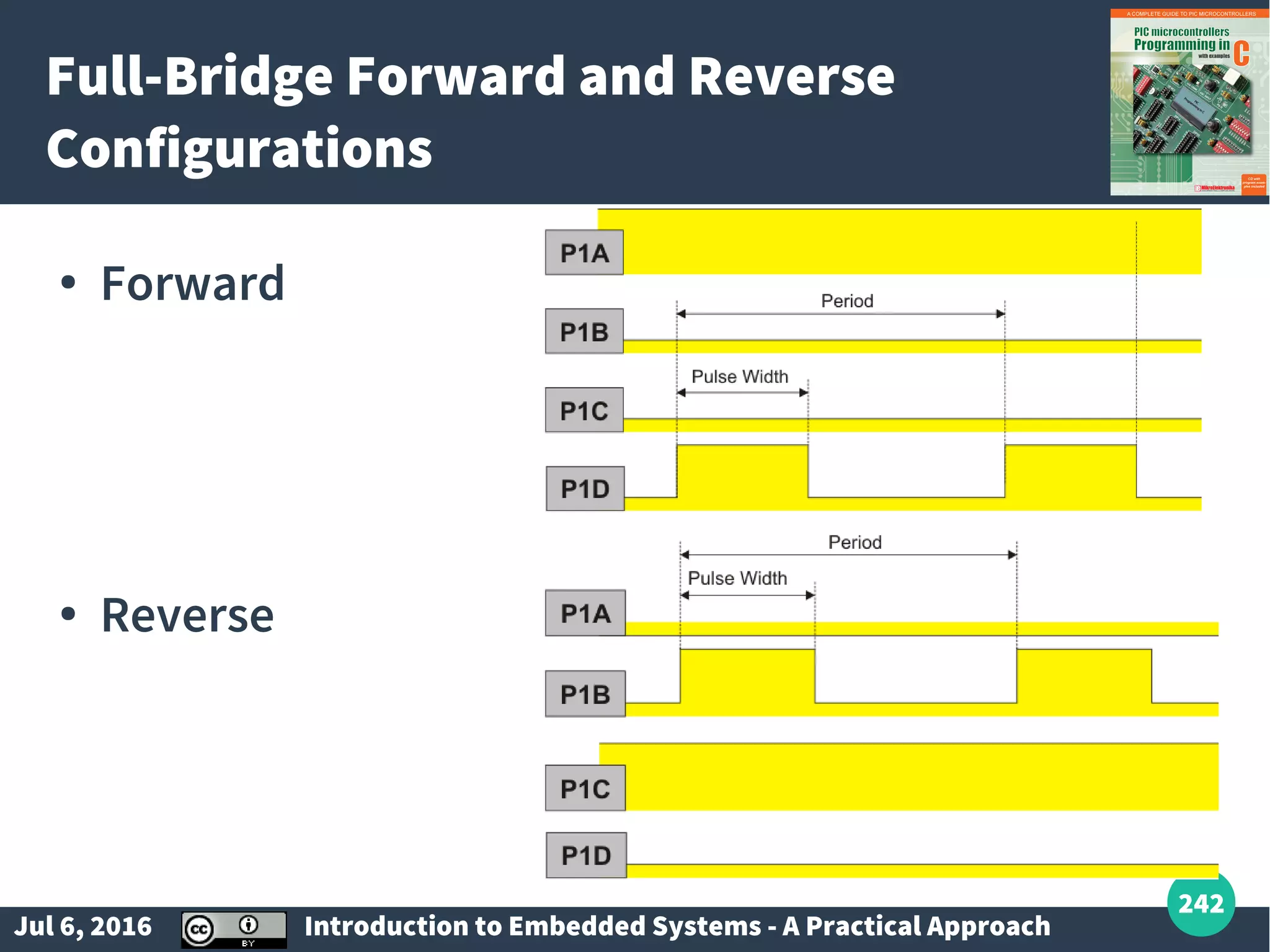
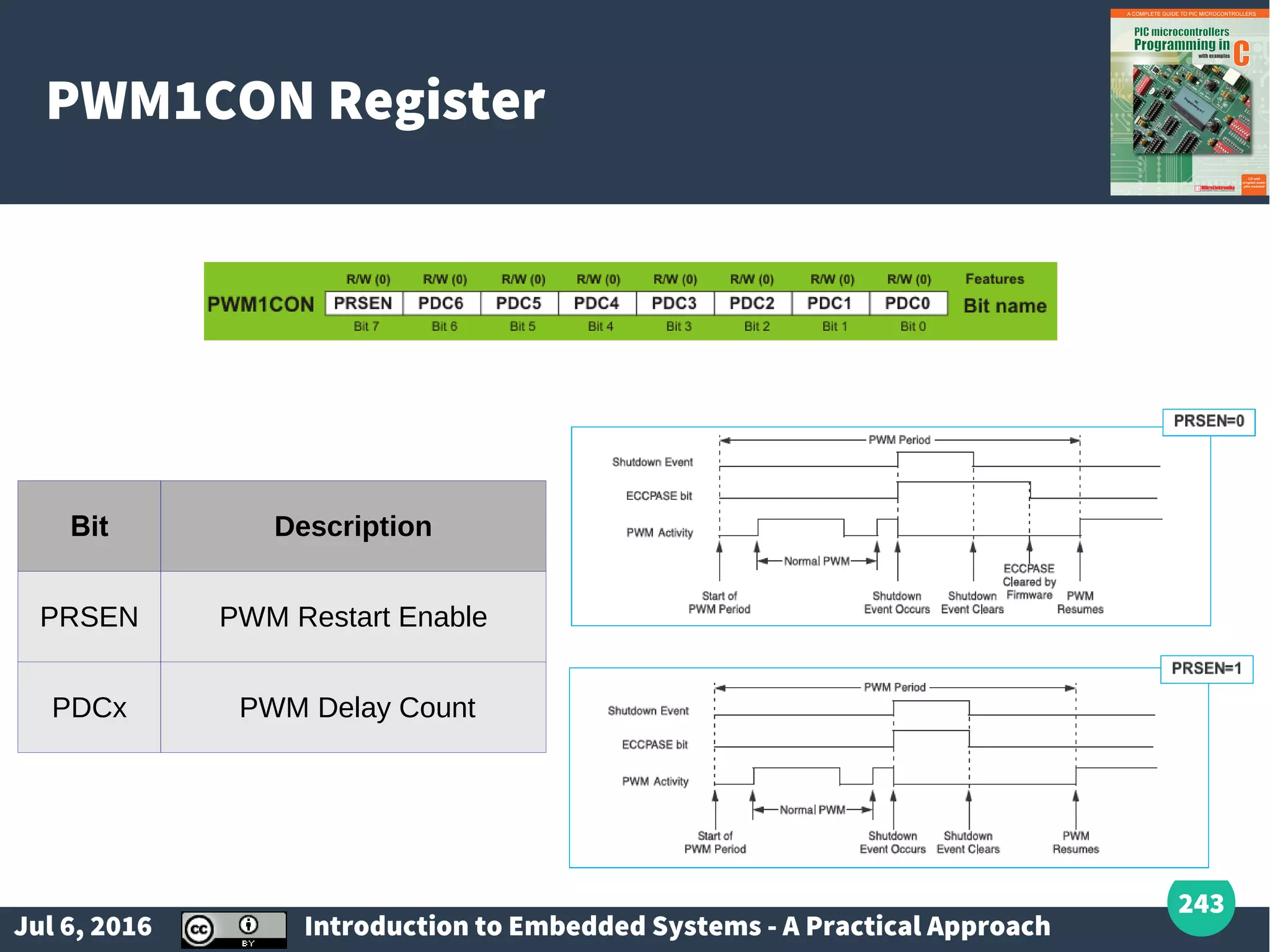
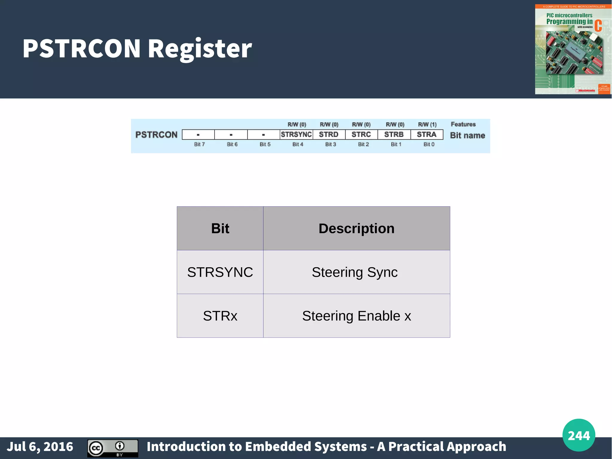
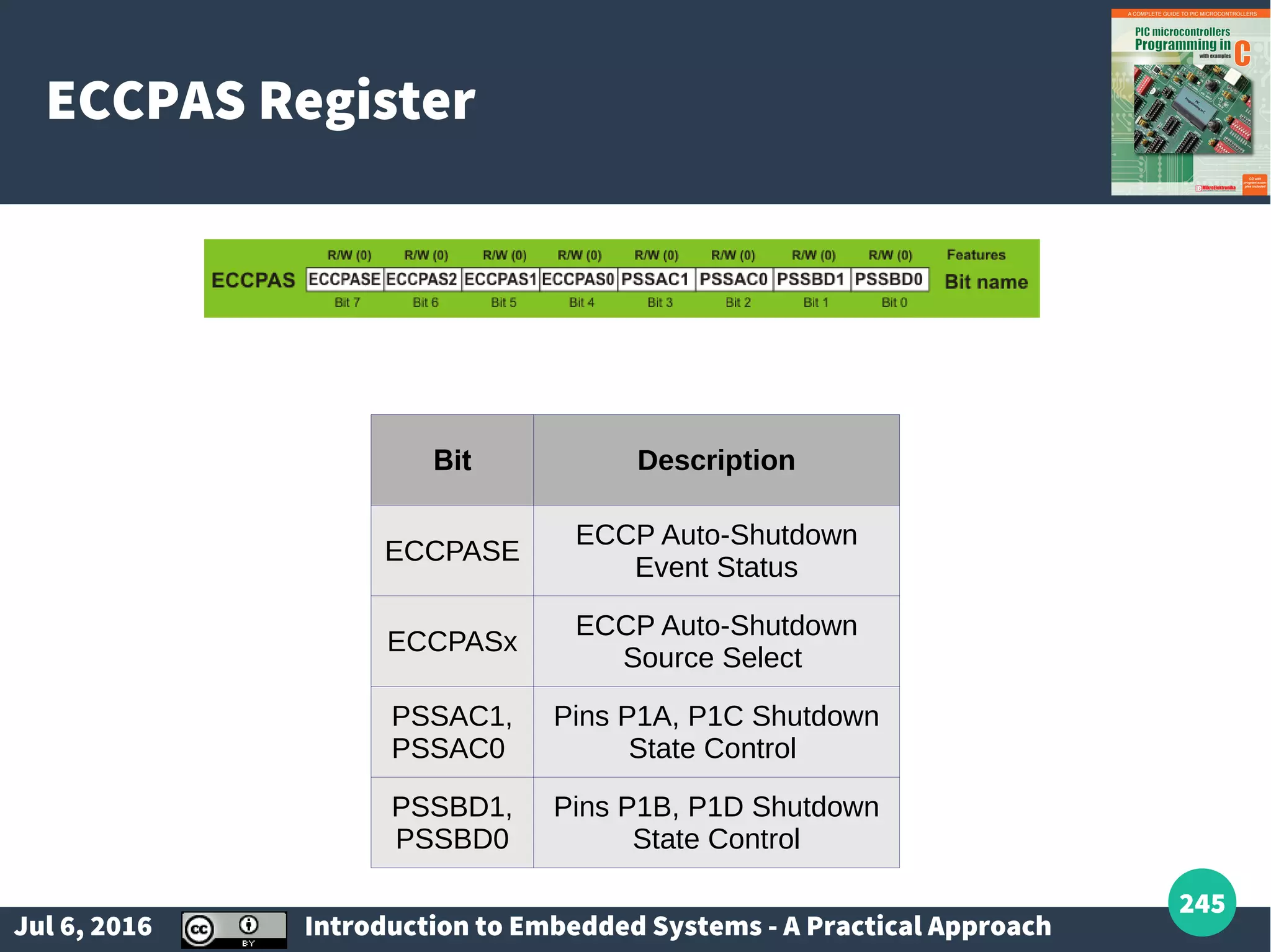
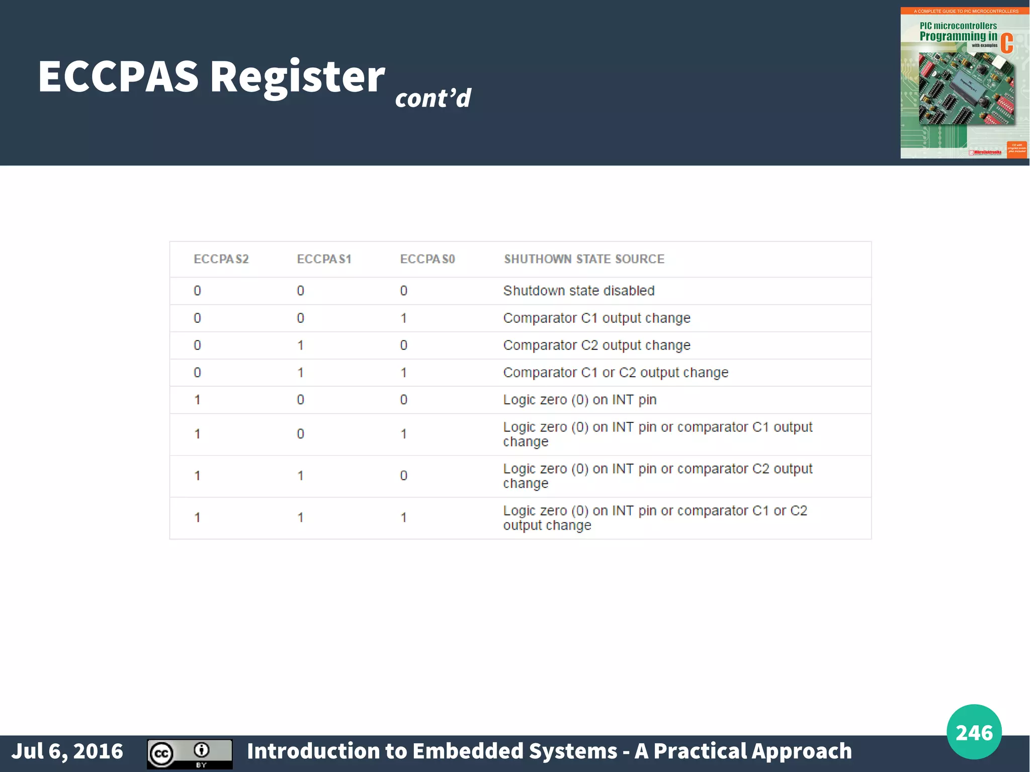
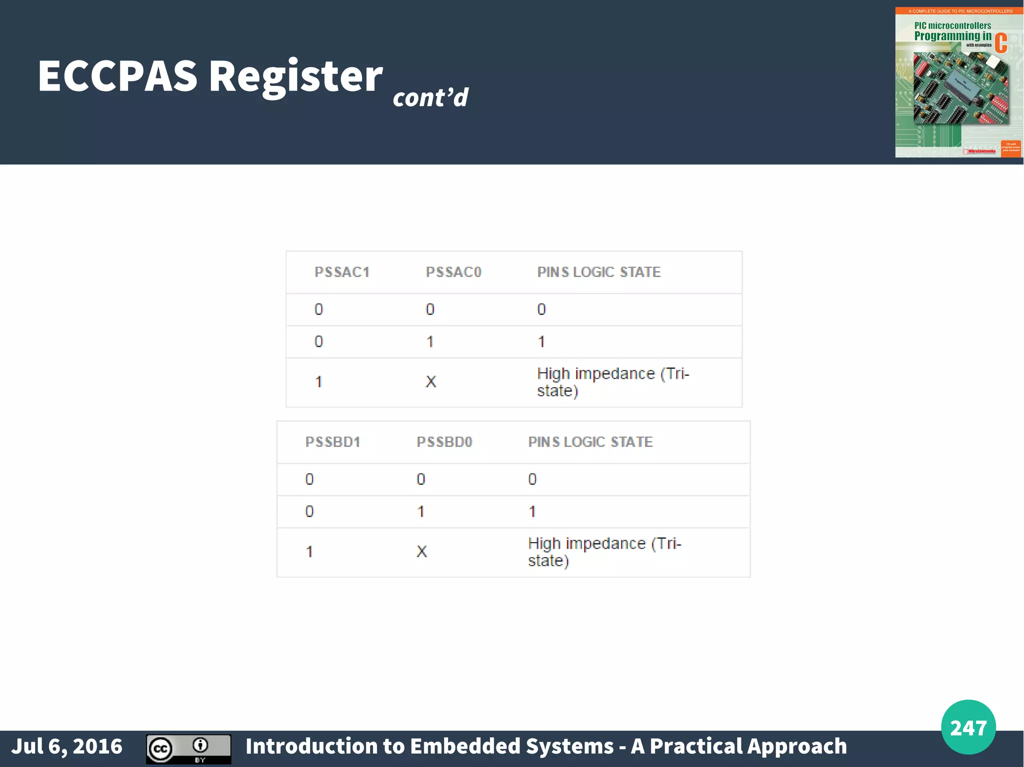
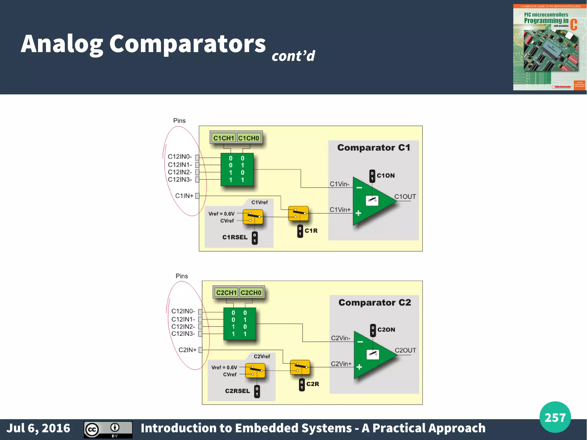
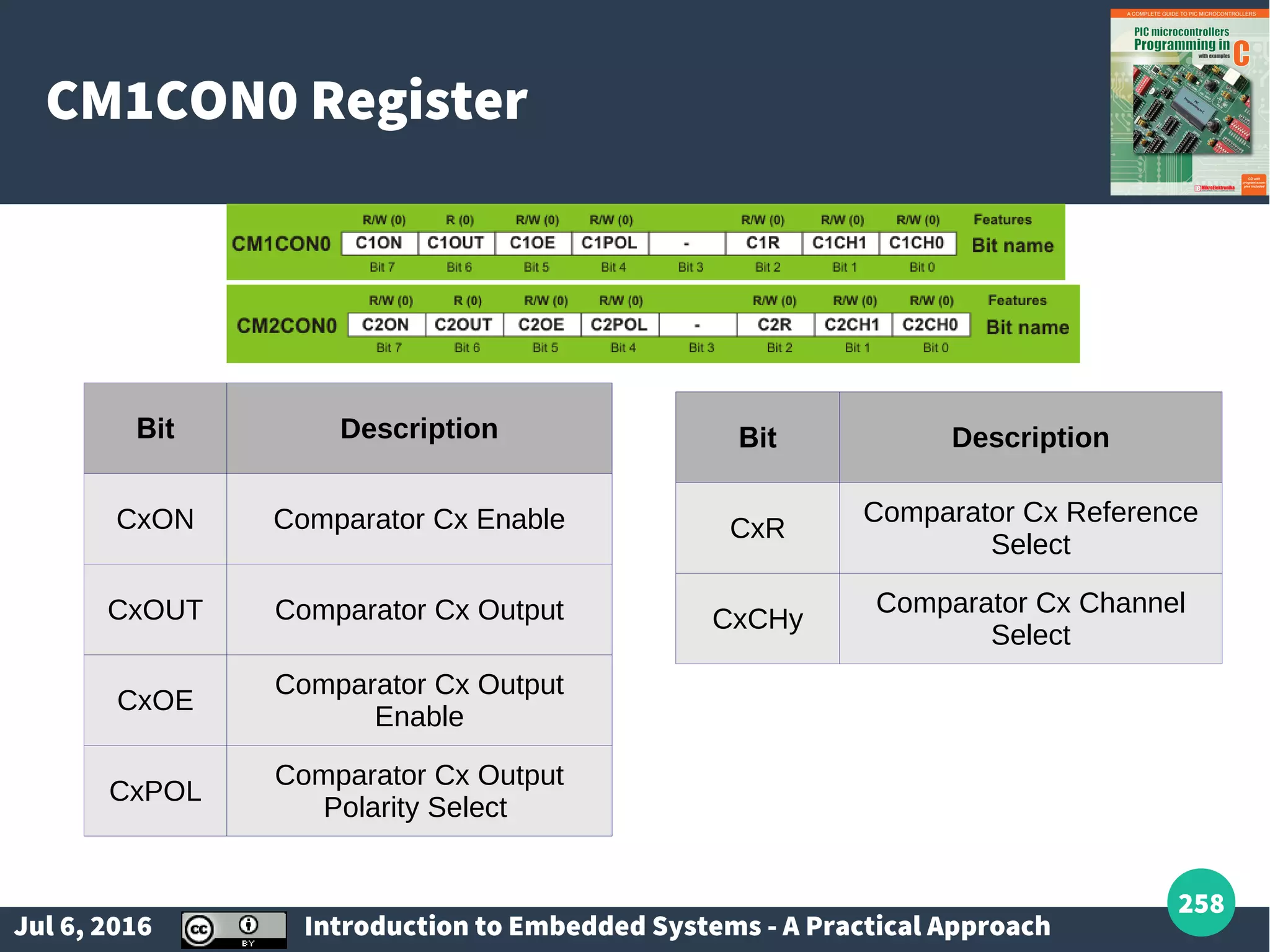
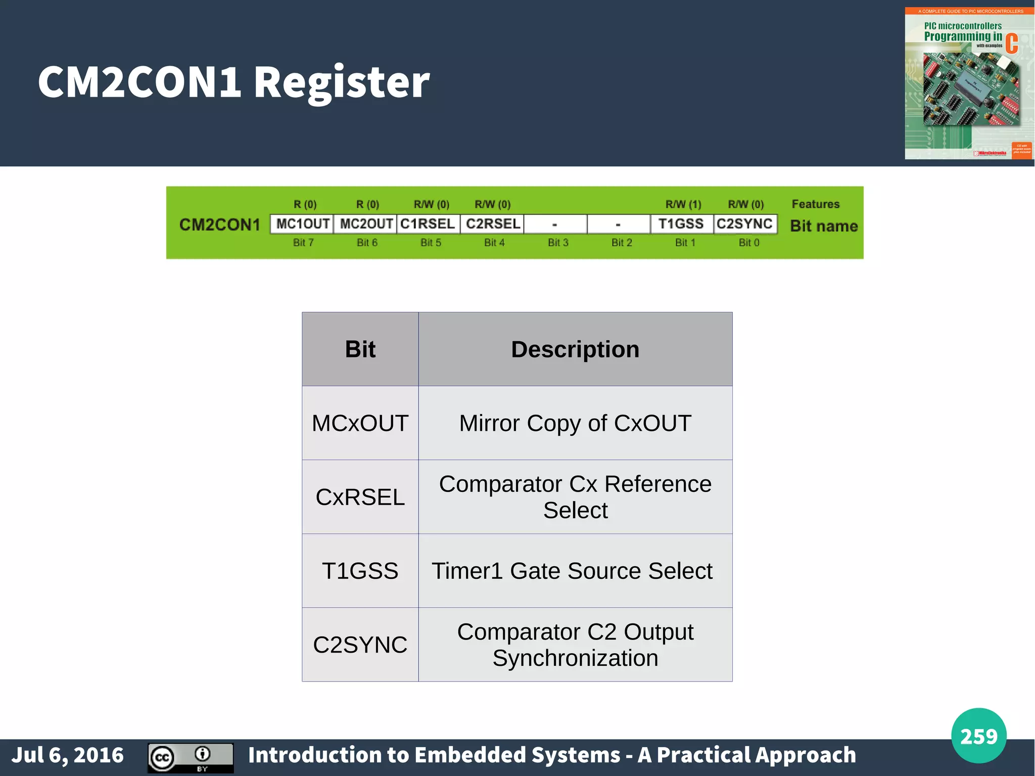
Detailed analysis of interrupts, ports in PIC16F887, and handling mechanical devices like switches and relays.
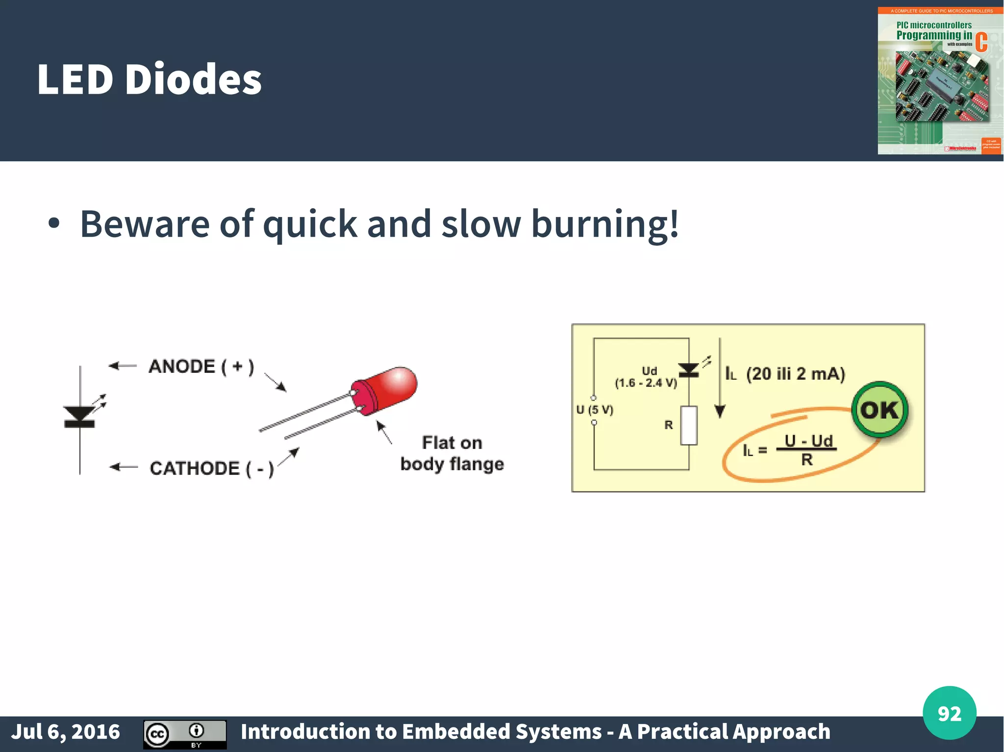
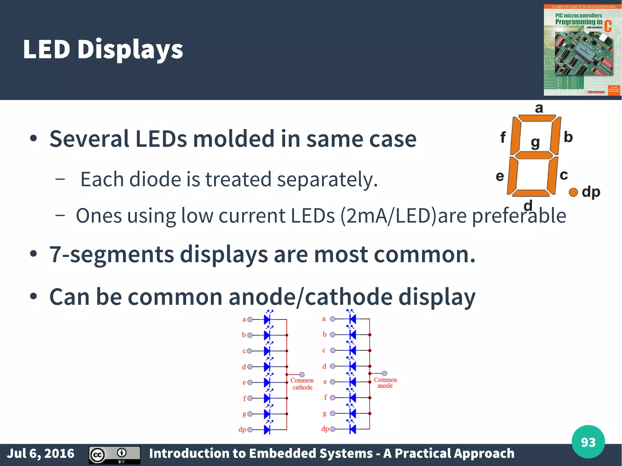
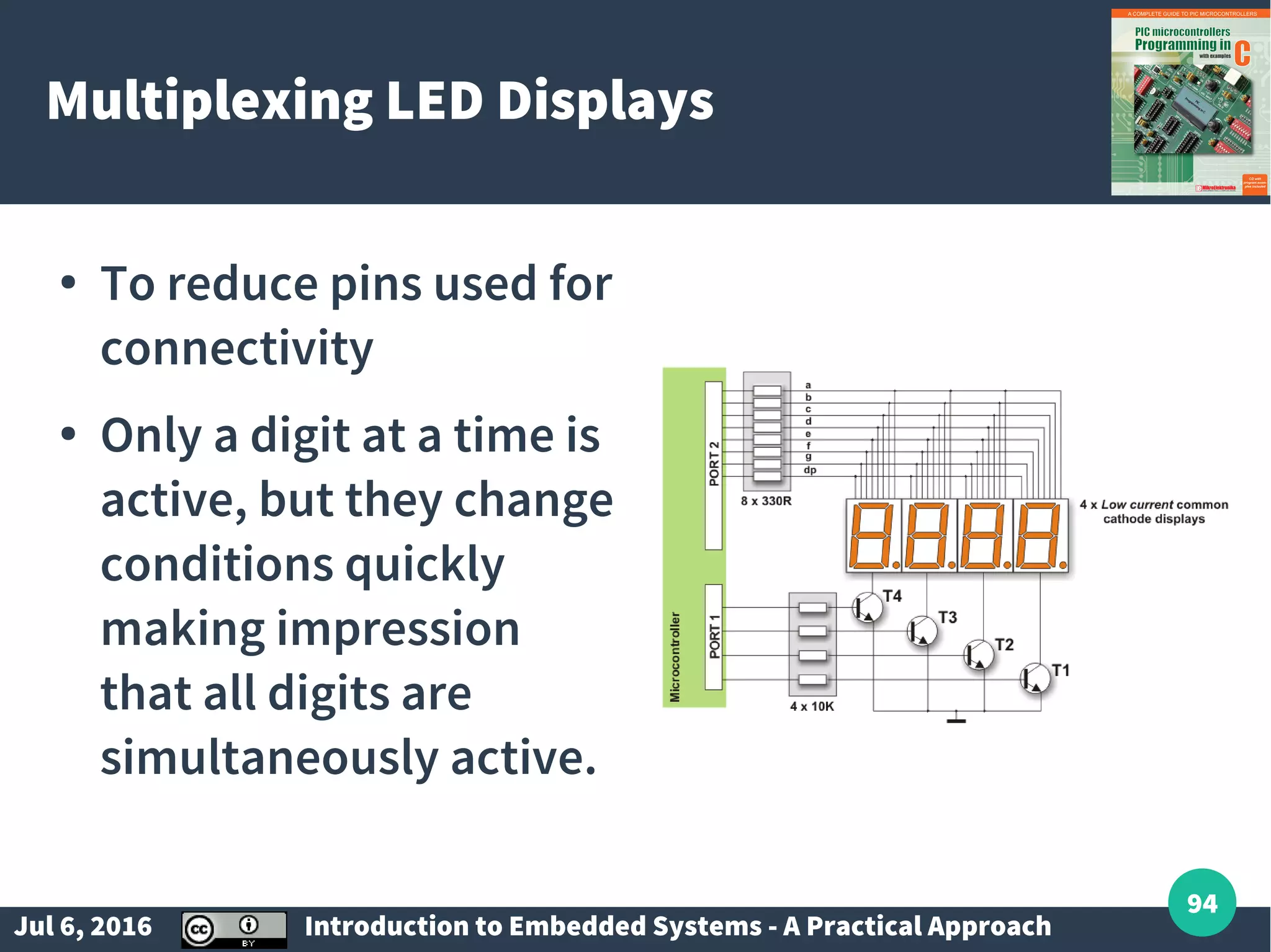
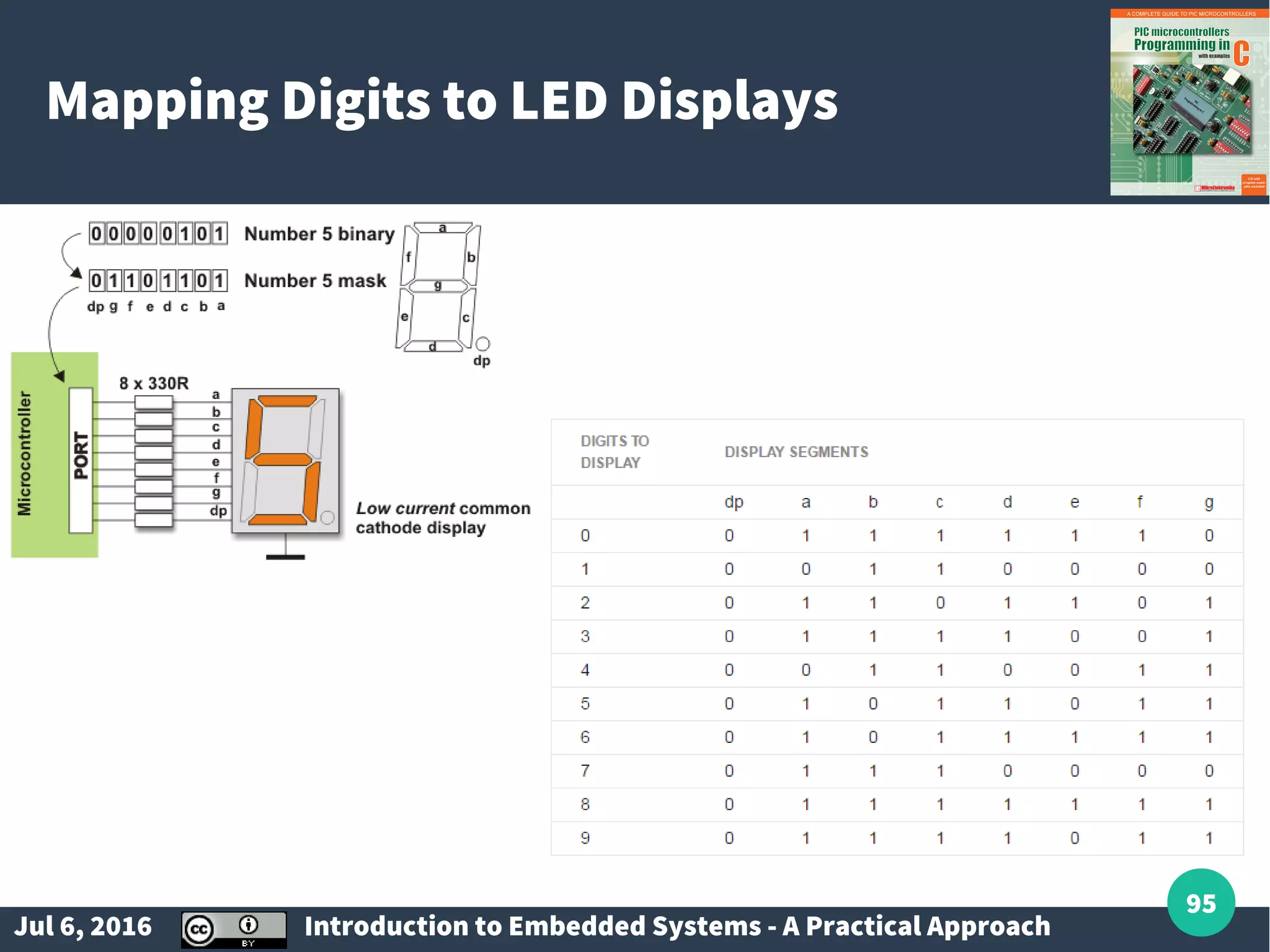
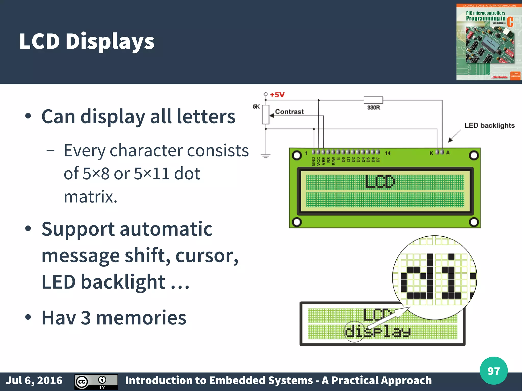
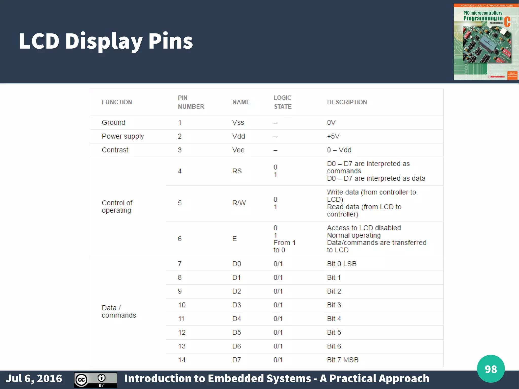
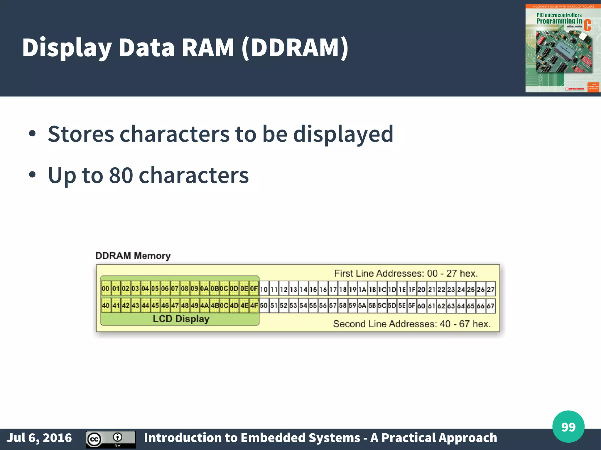
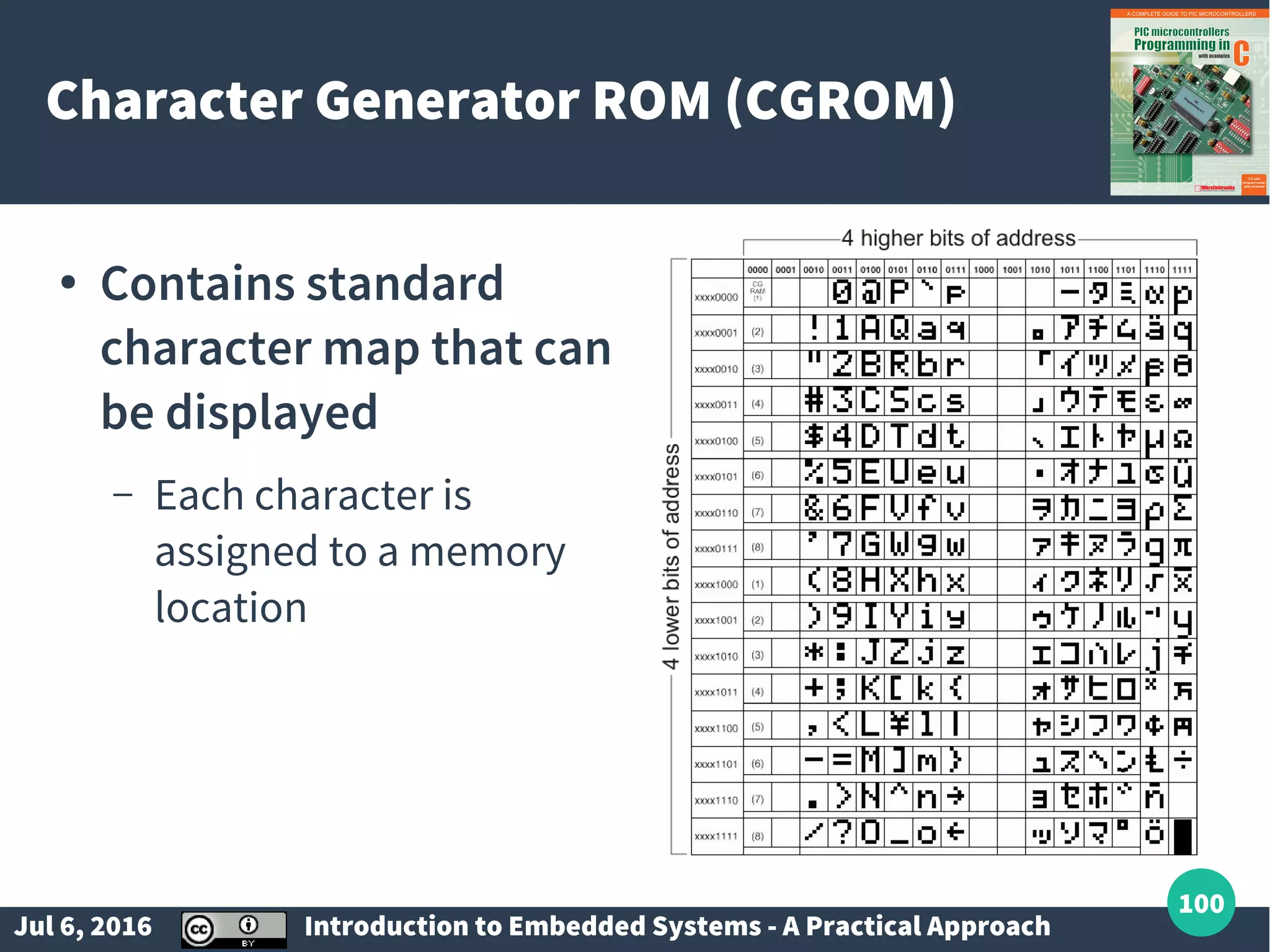
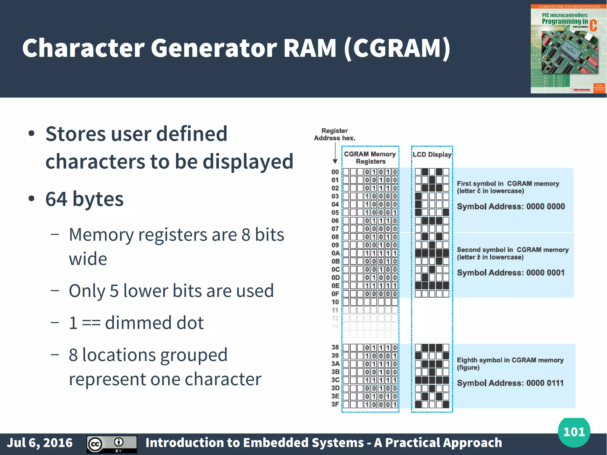
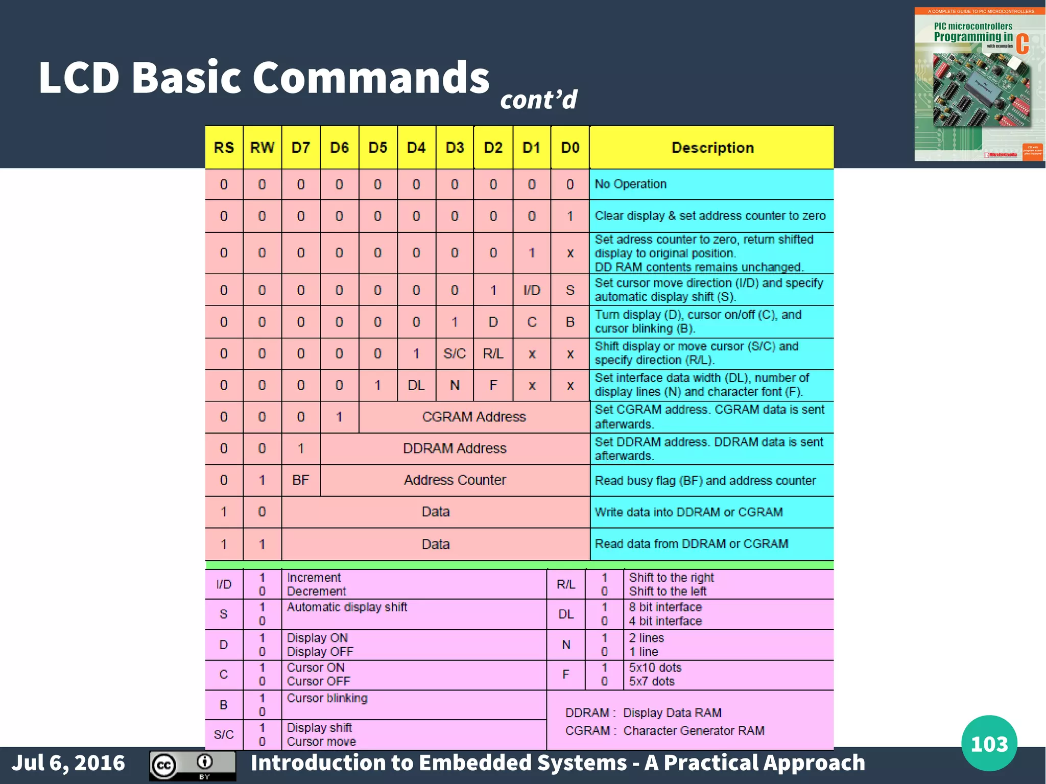
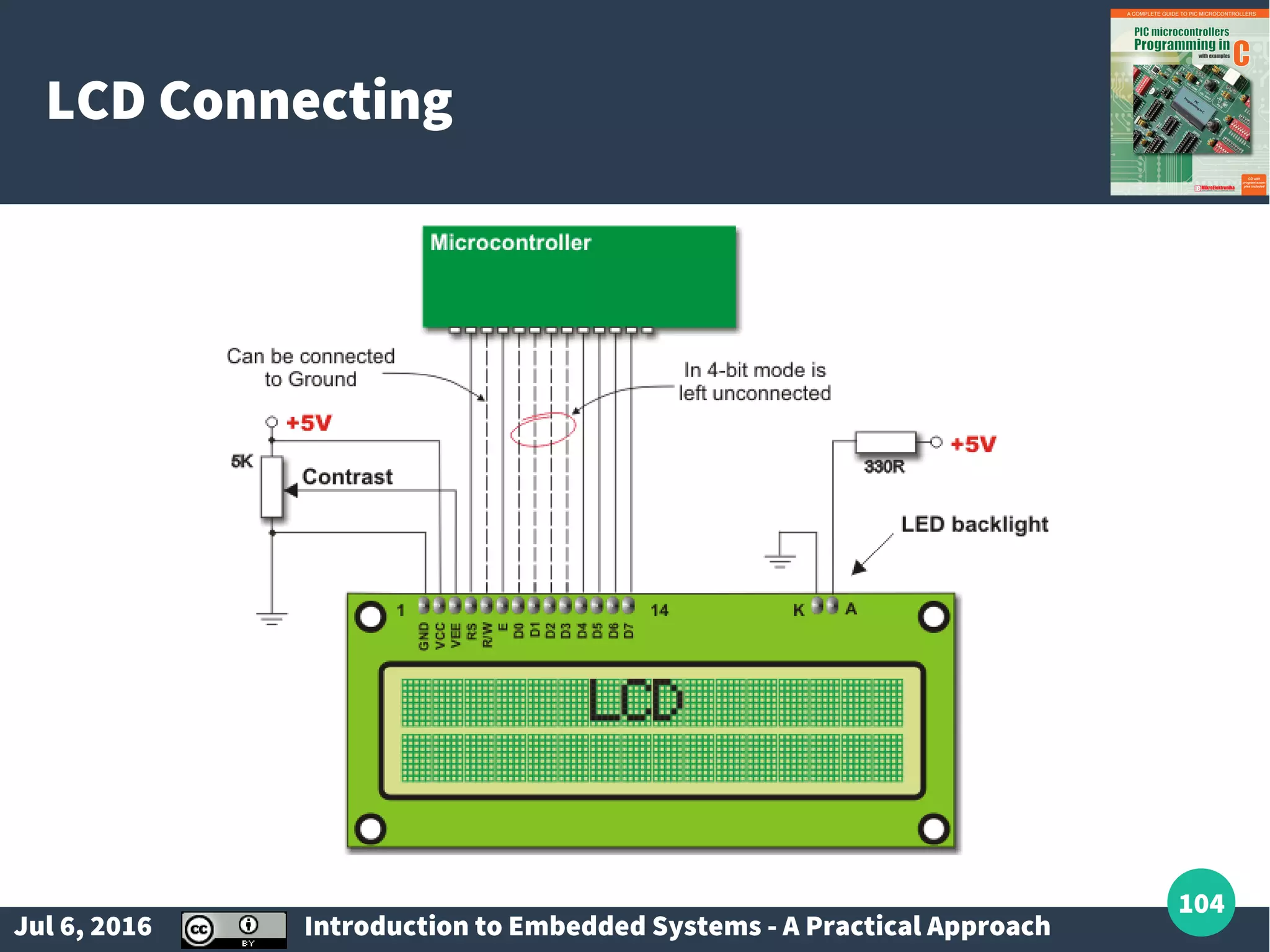
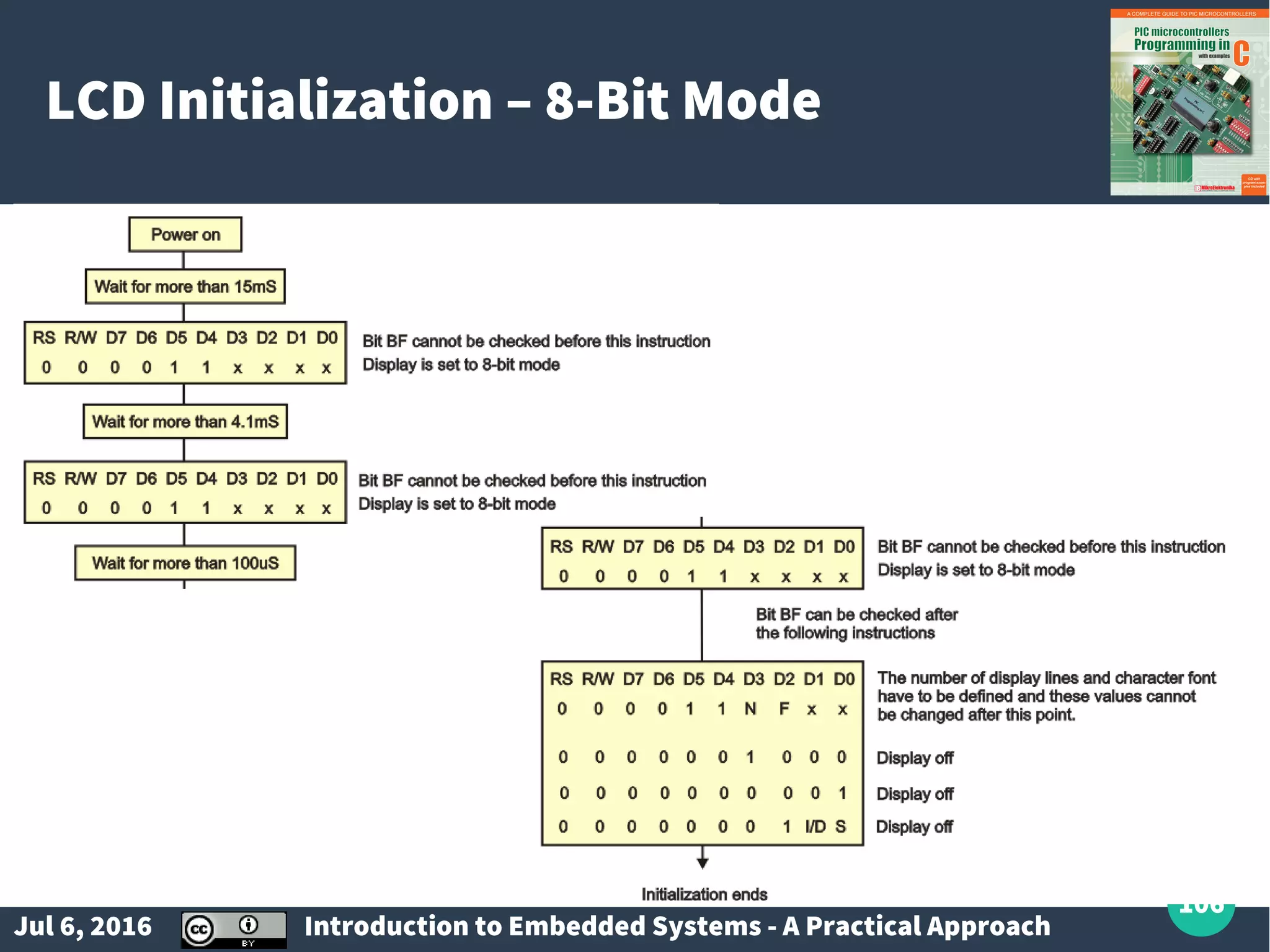
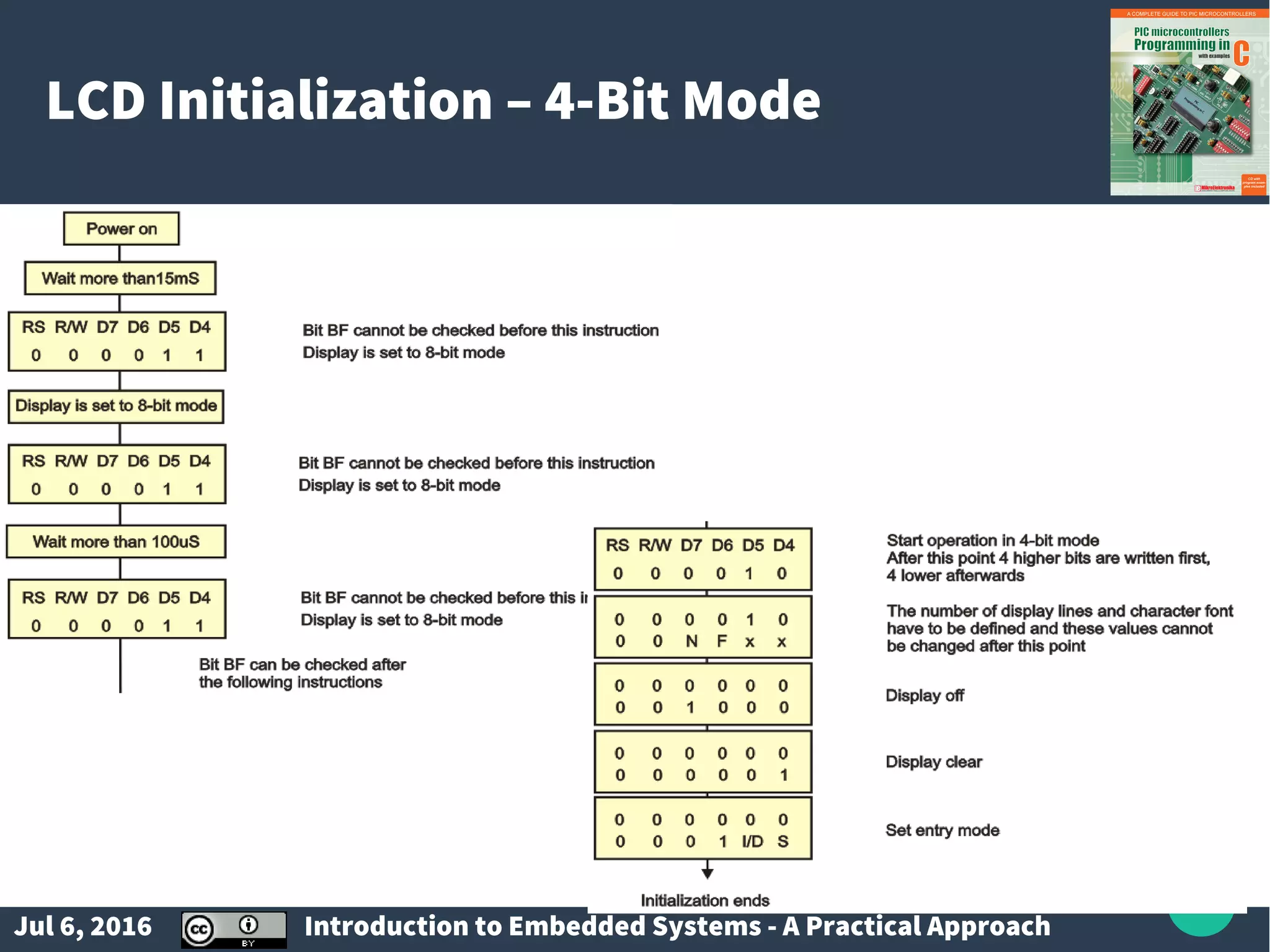
Introduction to display types including LED and LCD, their commands, and interfacing techniques.
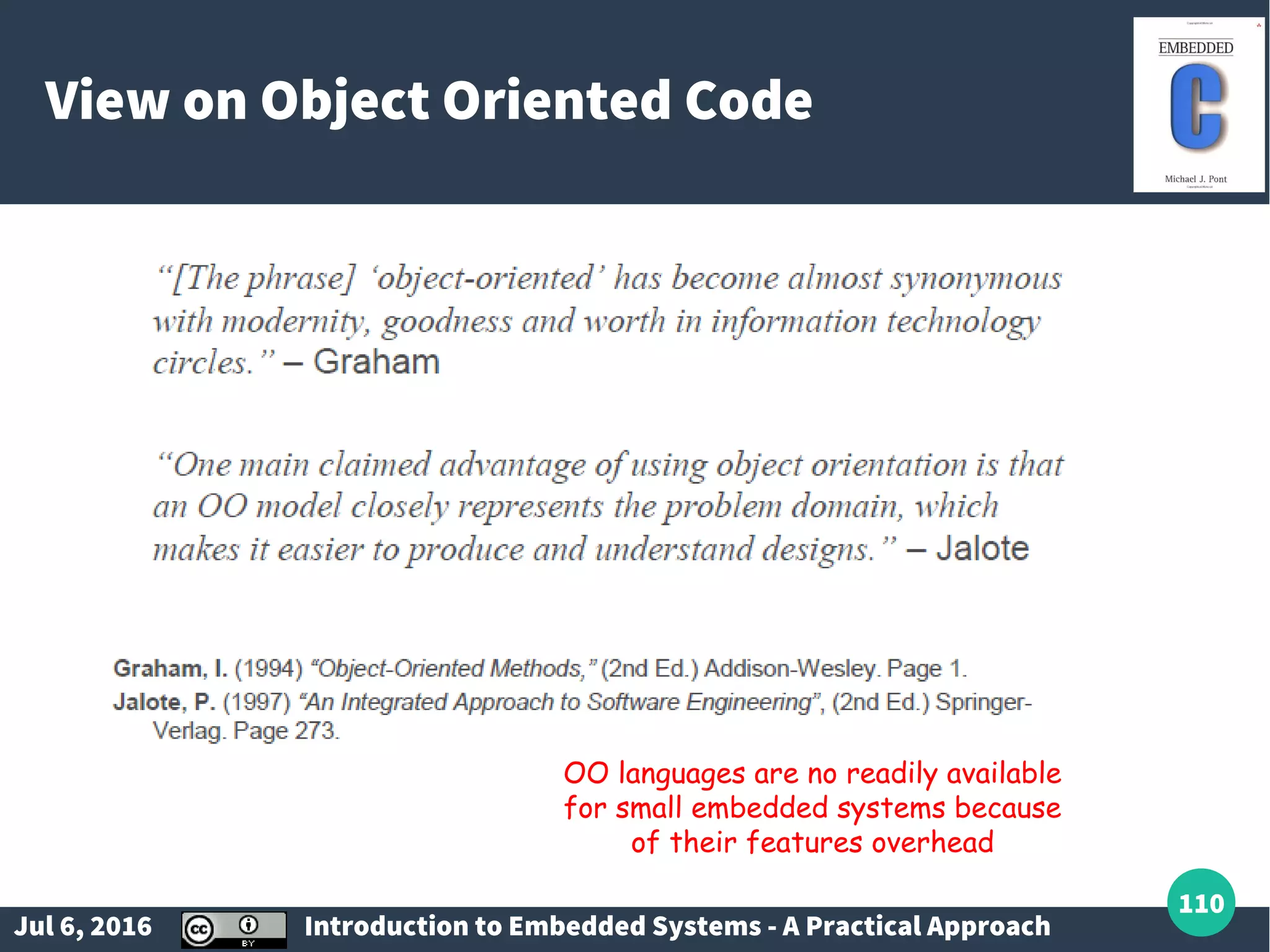
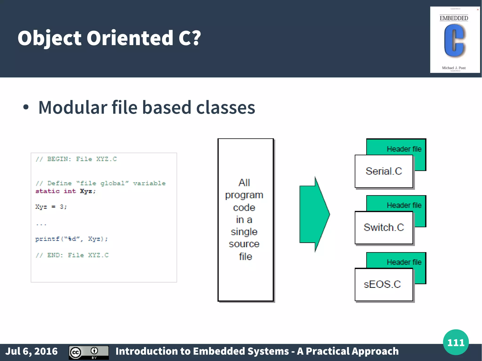
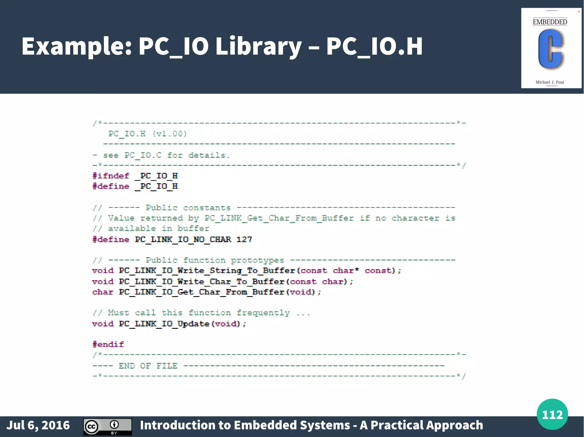
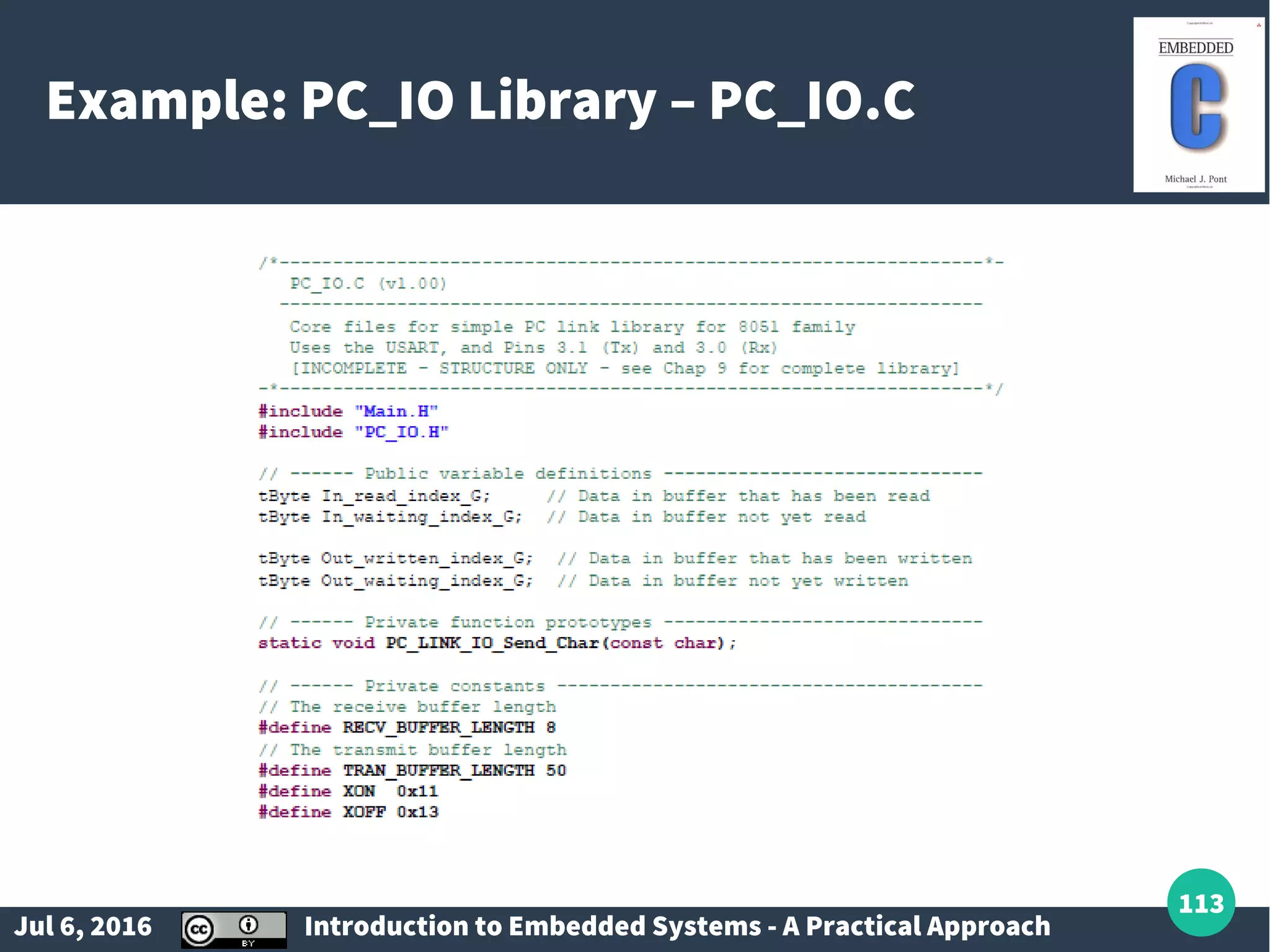
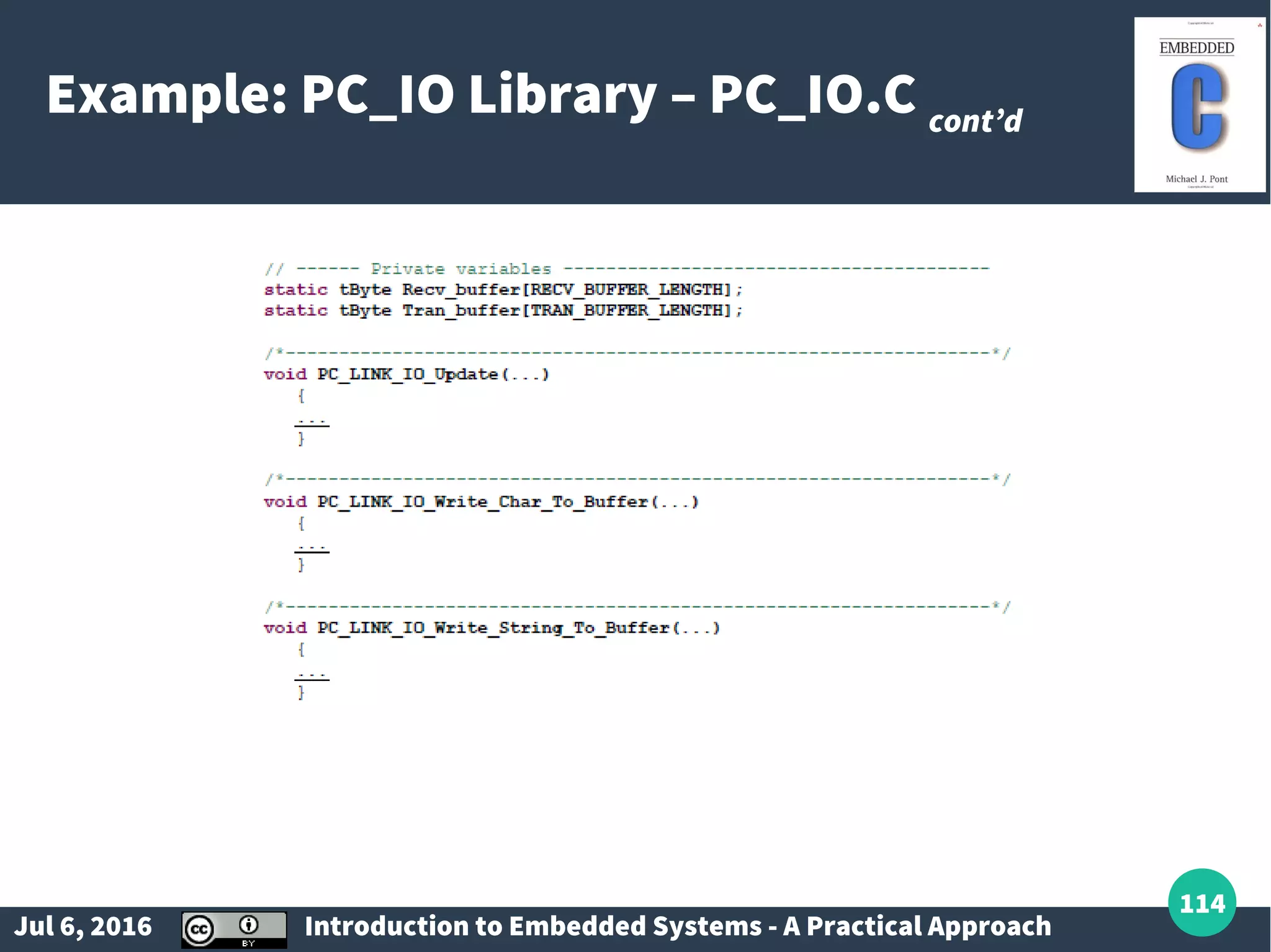
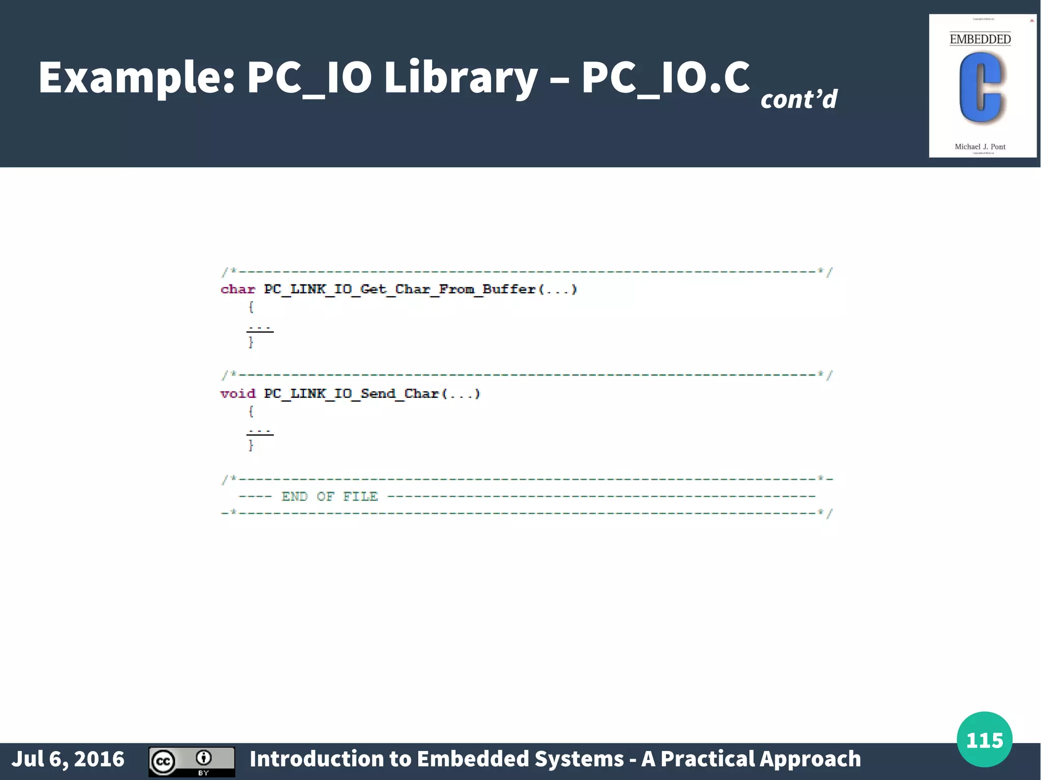
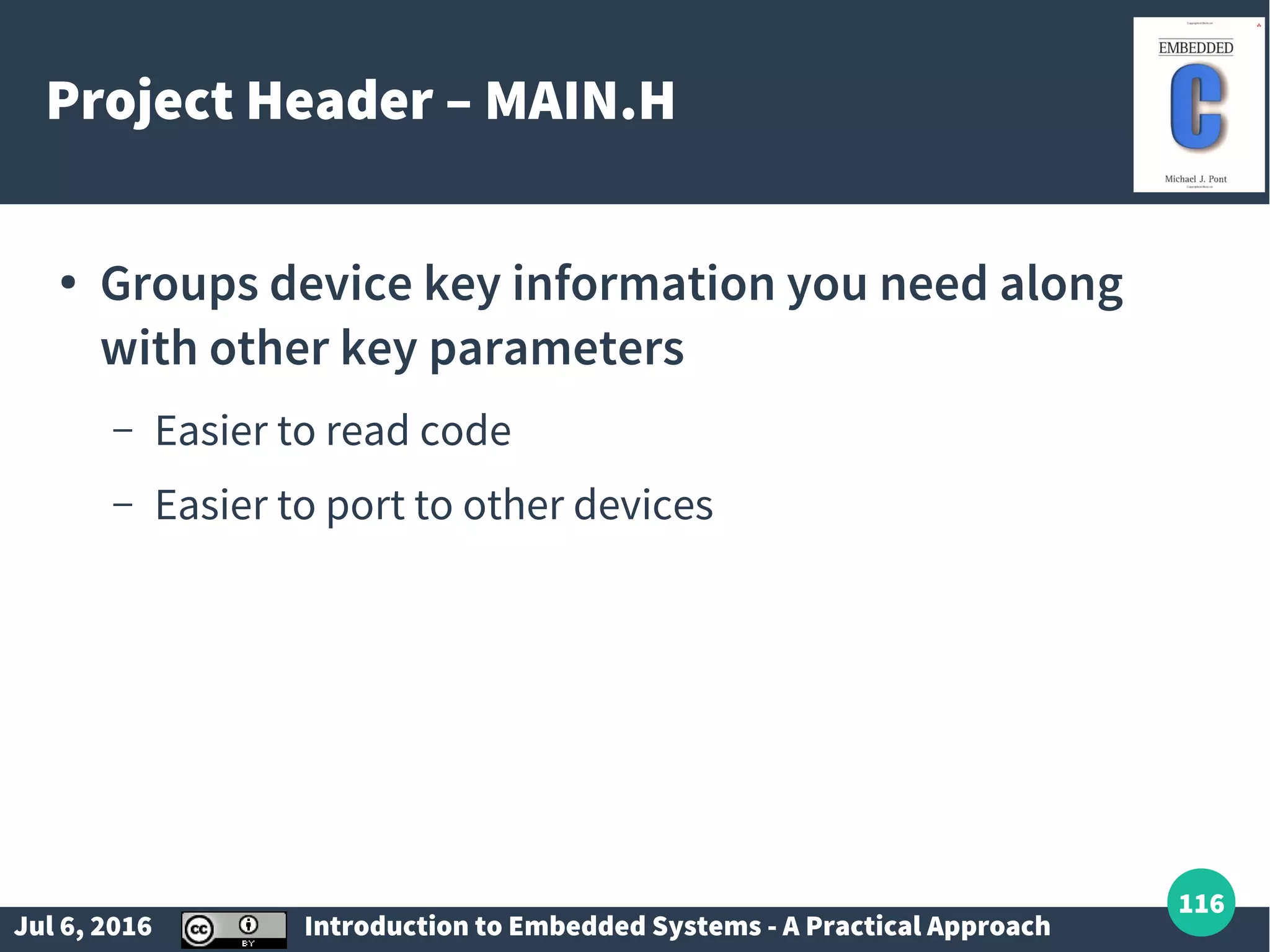
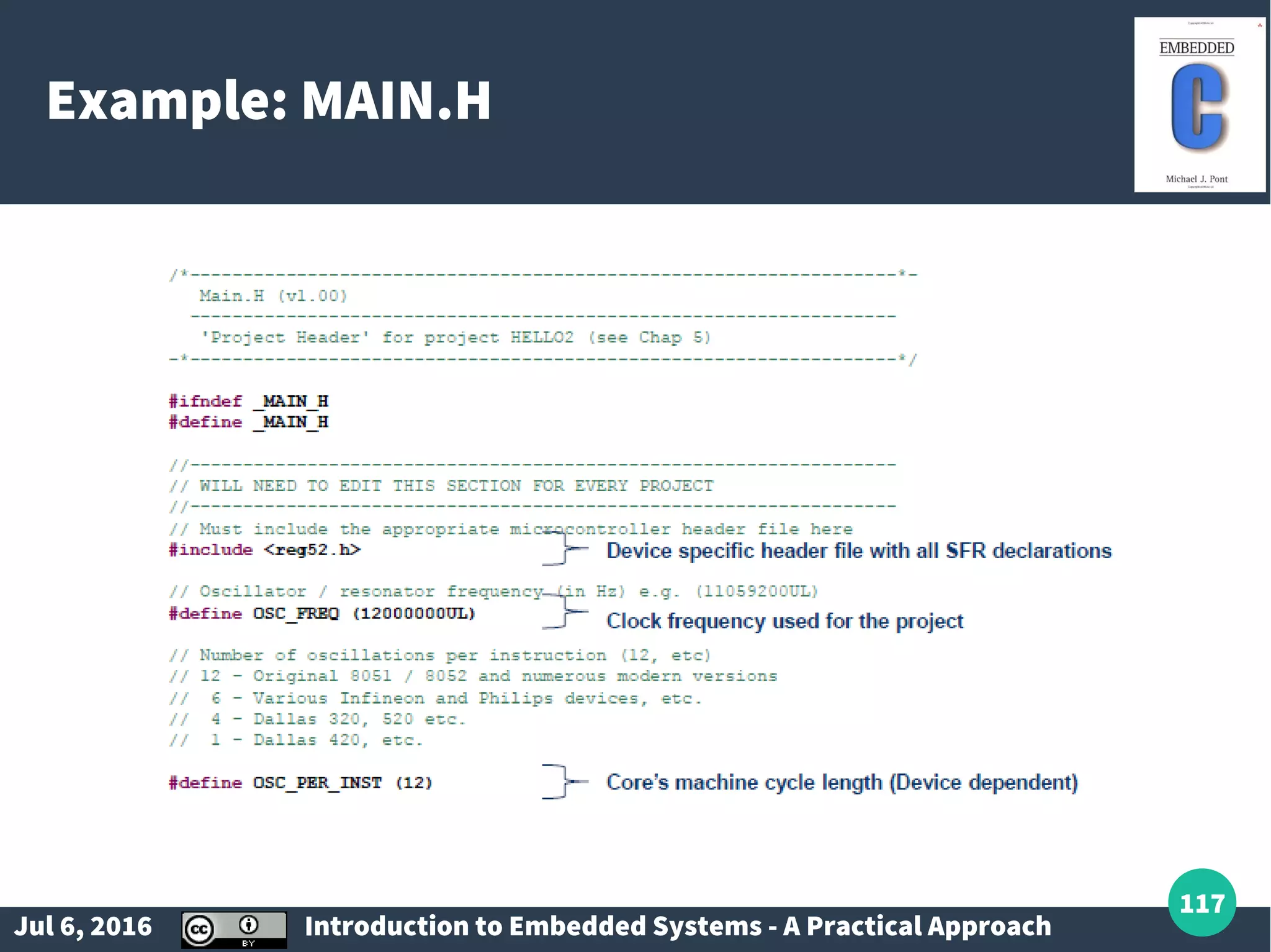
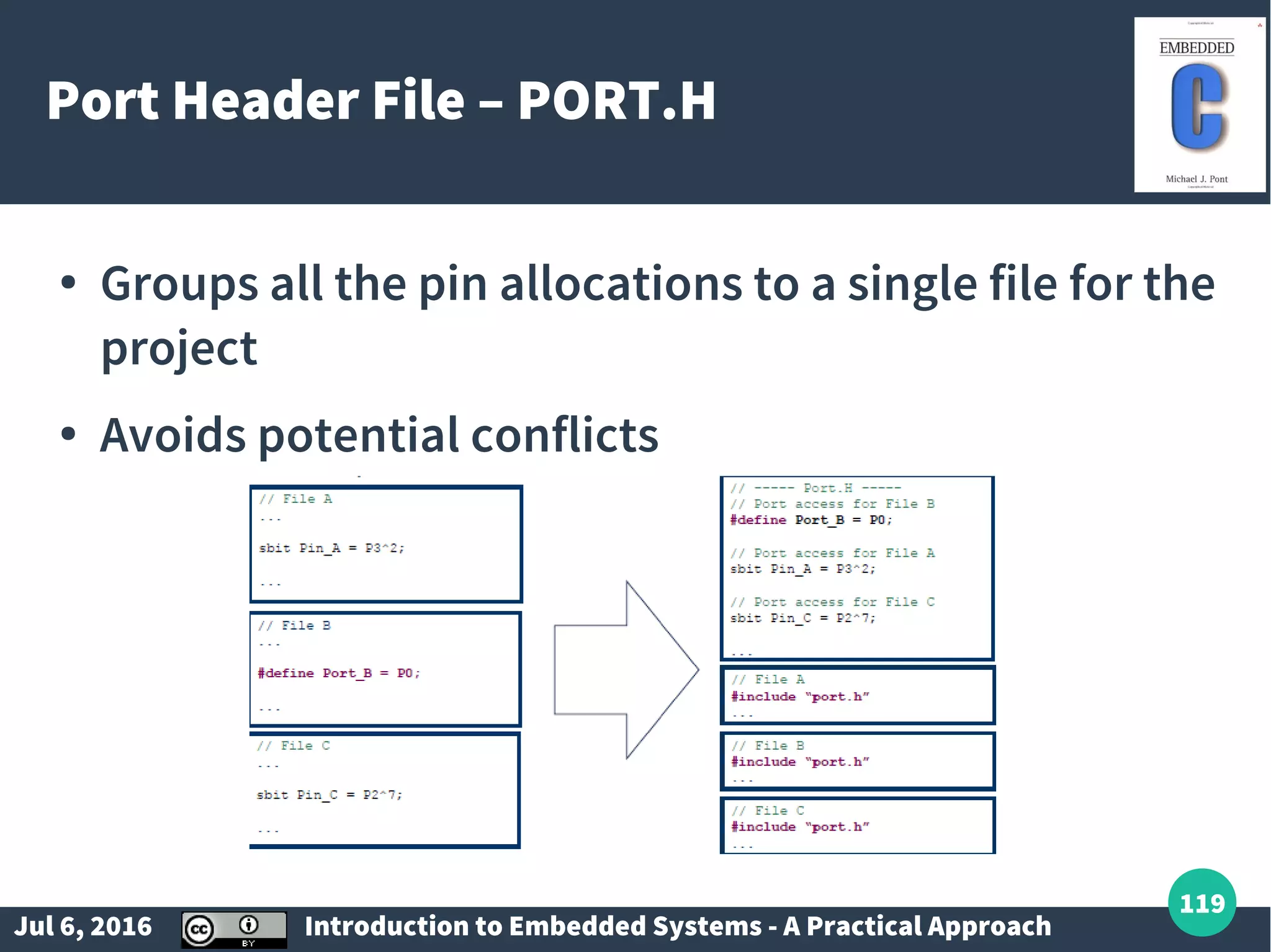
Introduction to object-oriented programming in C and the concept of modular file-based classes.
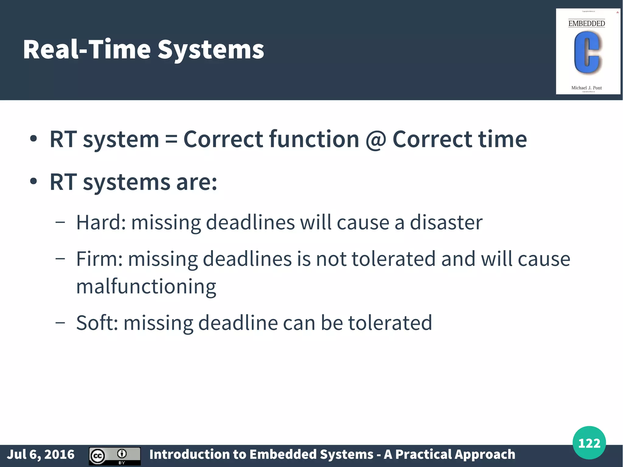
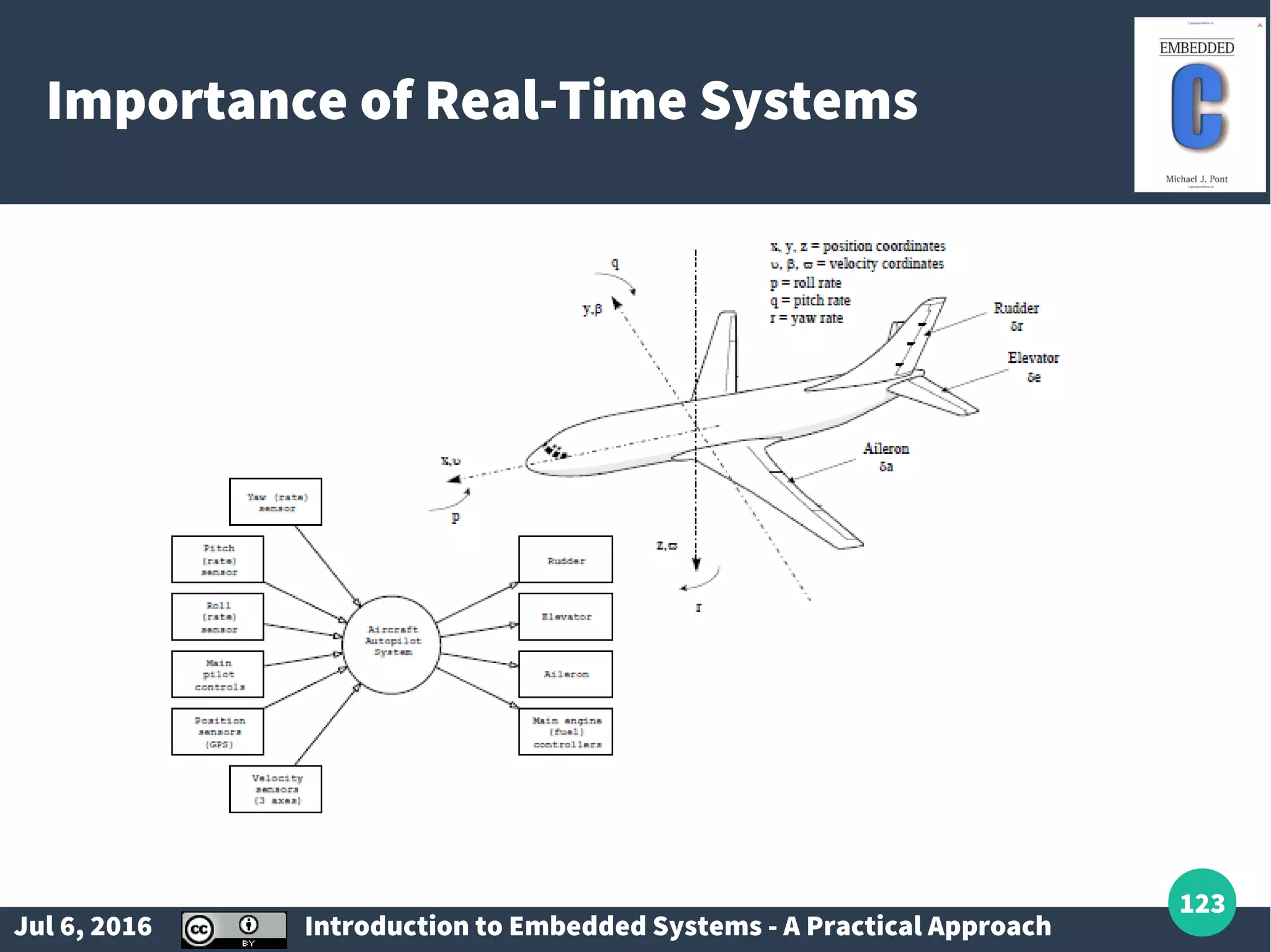
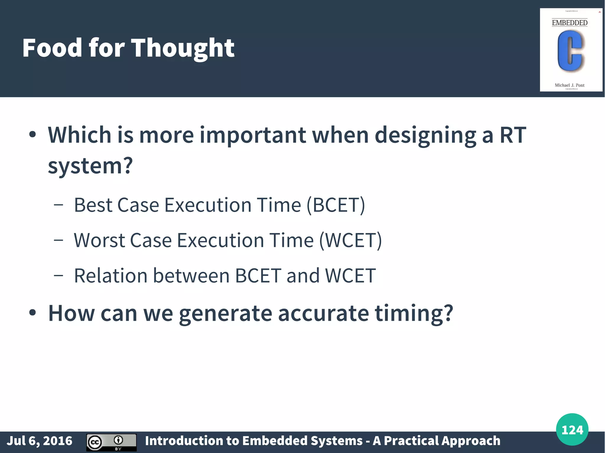
Definitions of real-time systems; characteristics of hard, firm, and soft real-time systems.
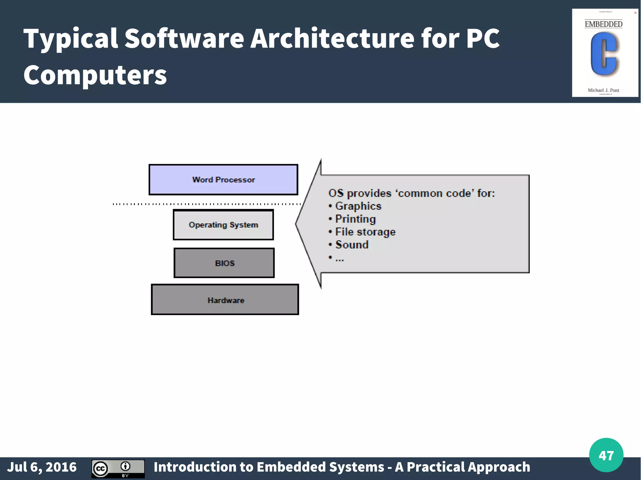
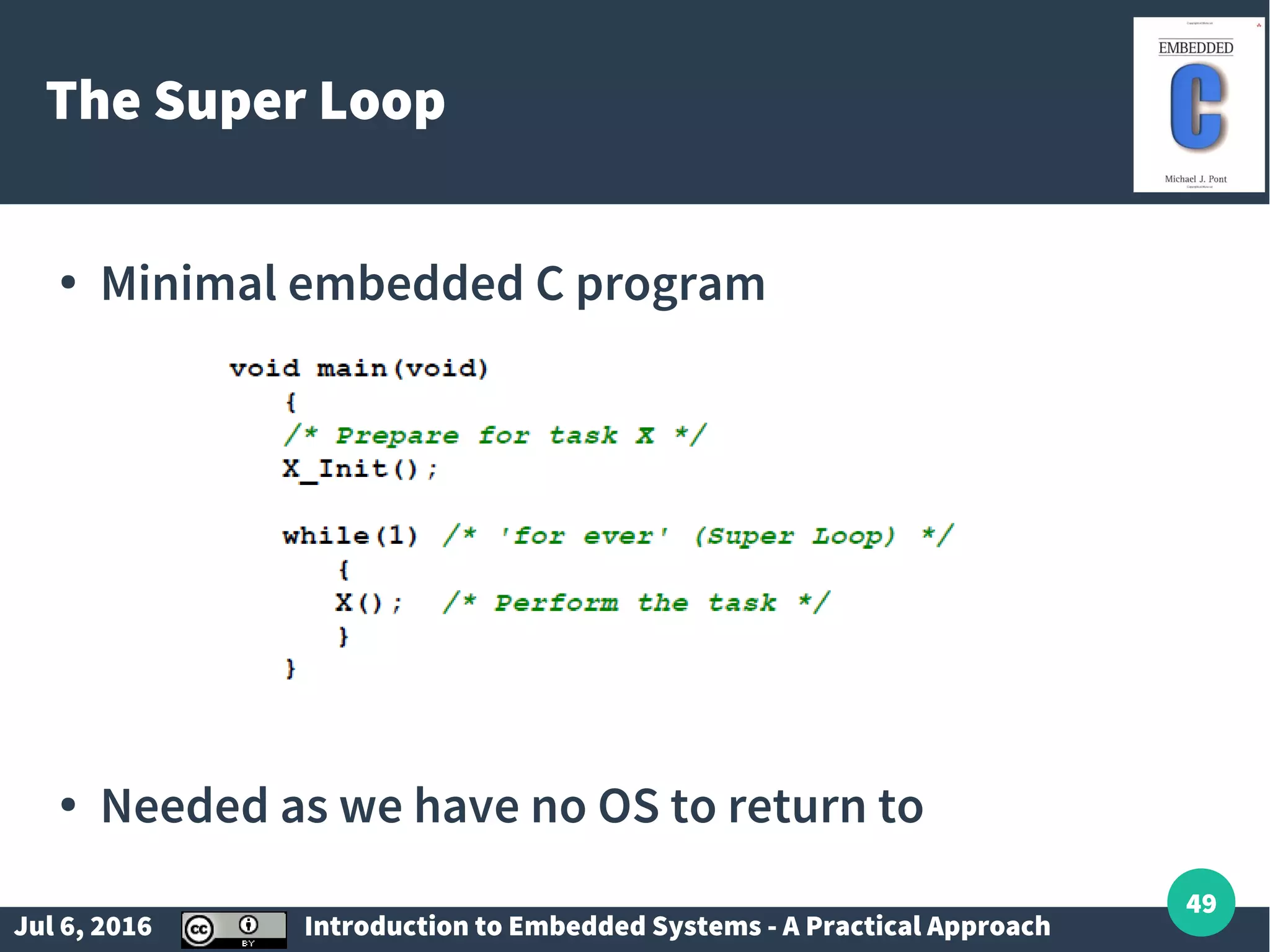
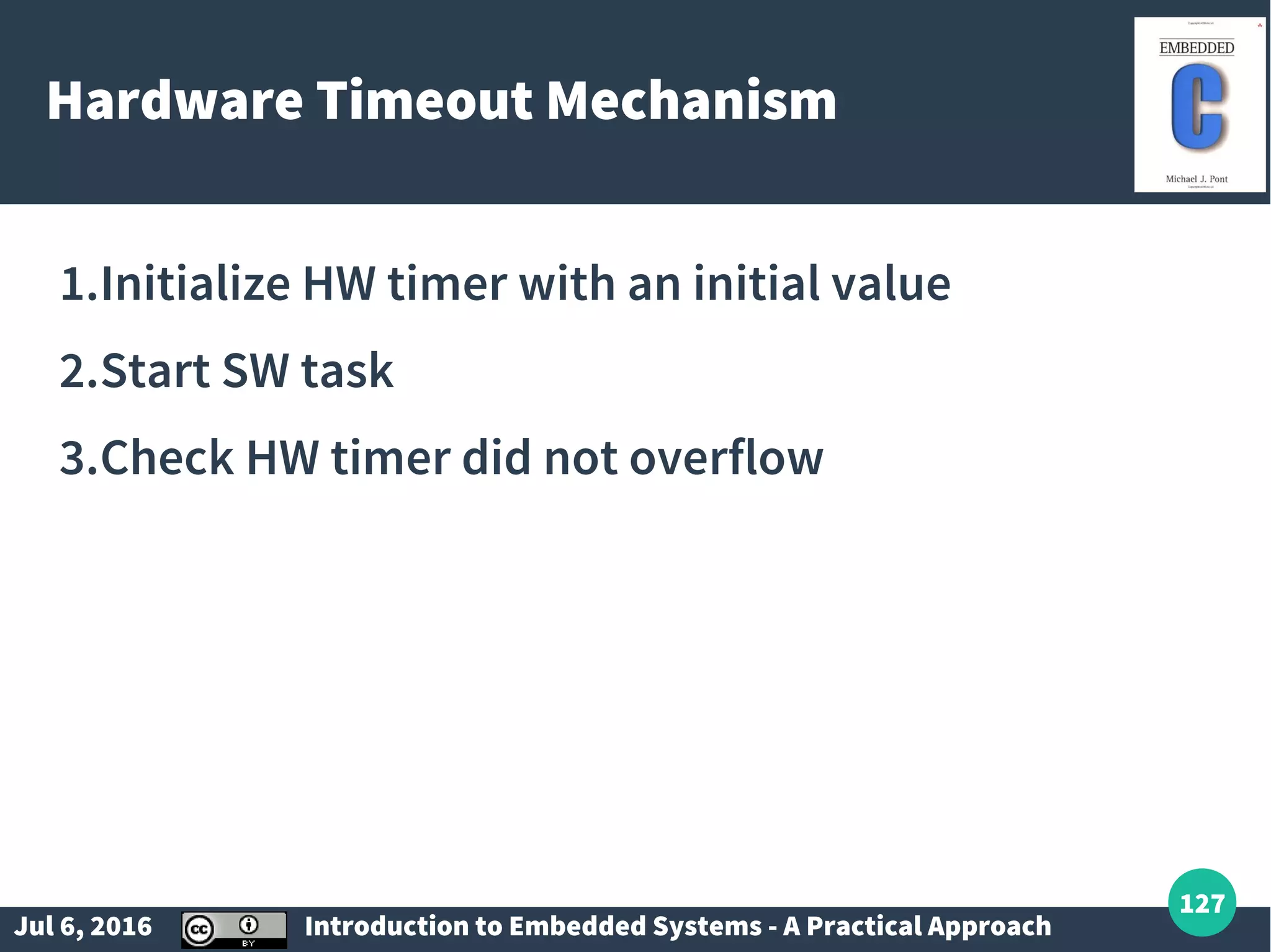
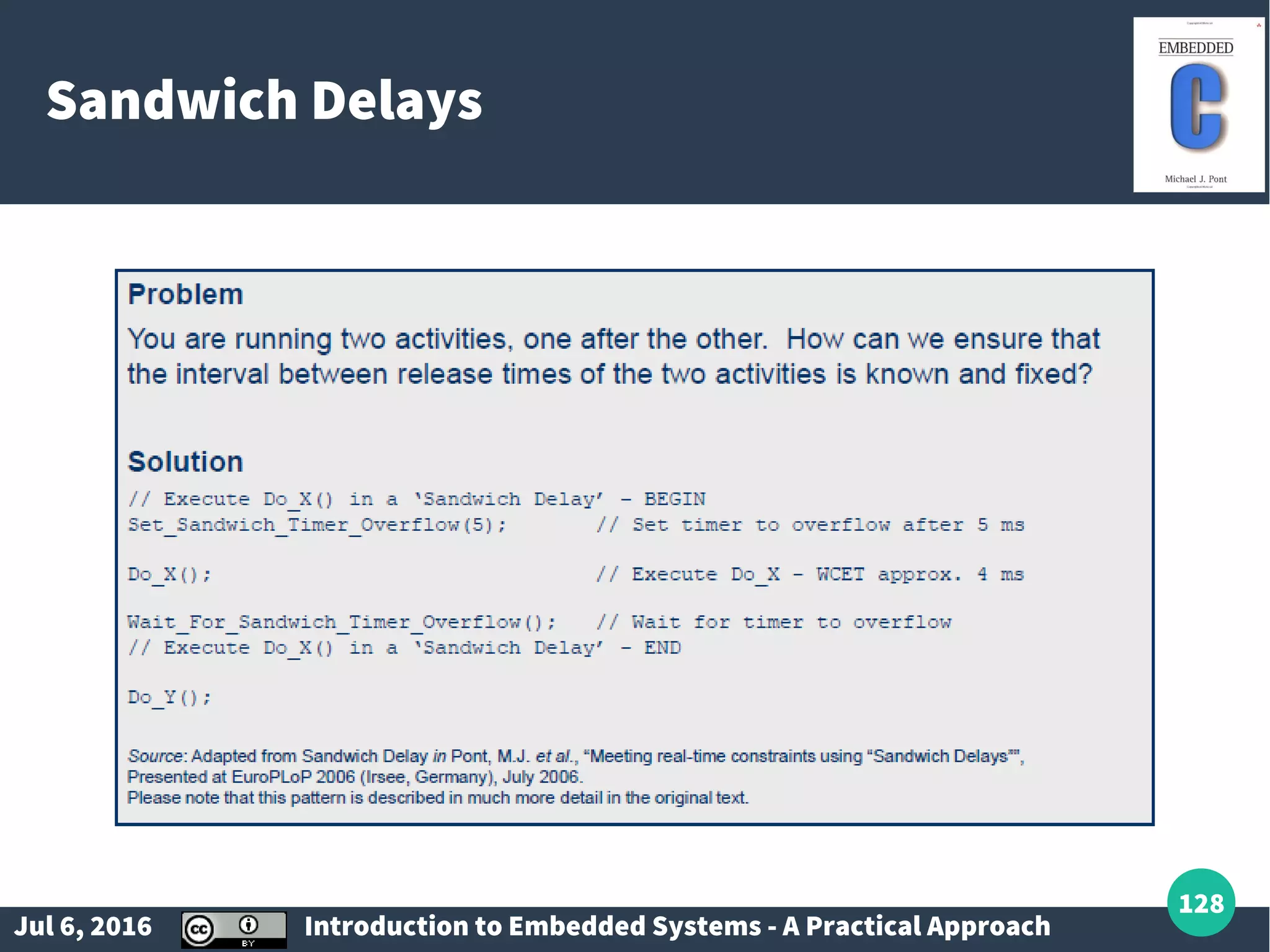
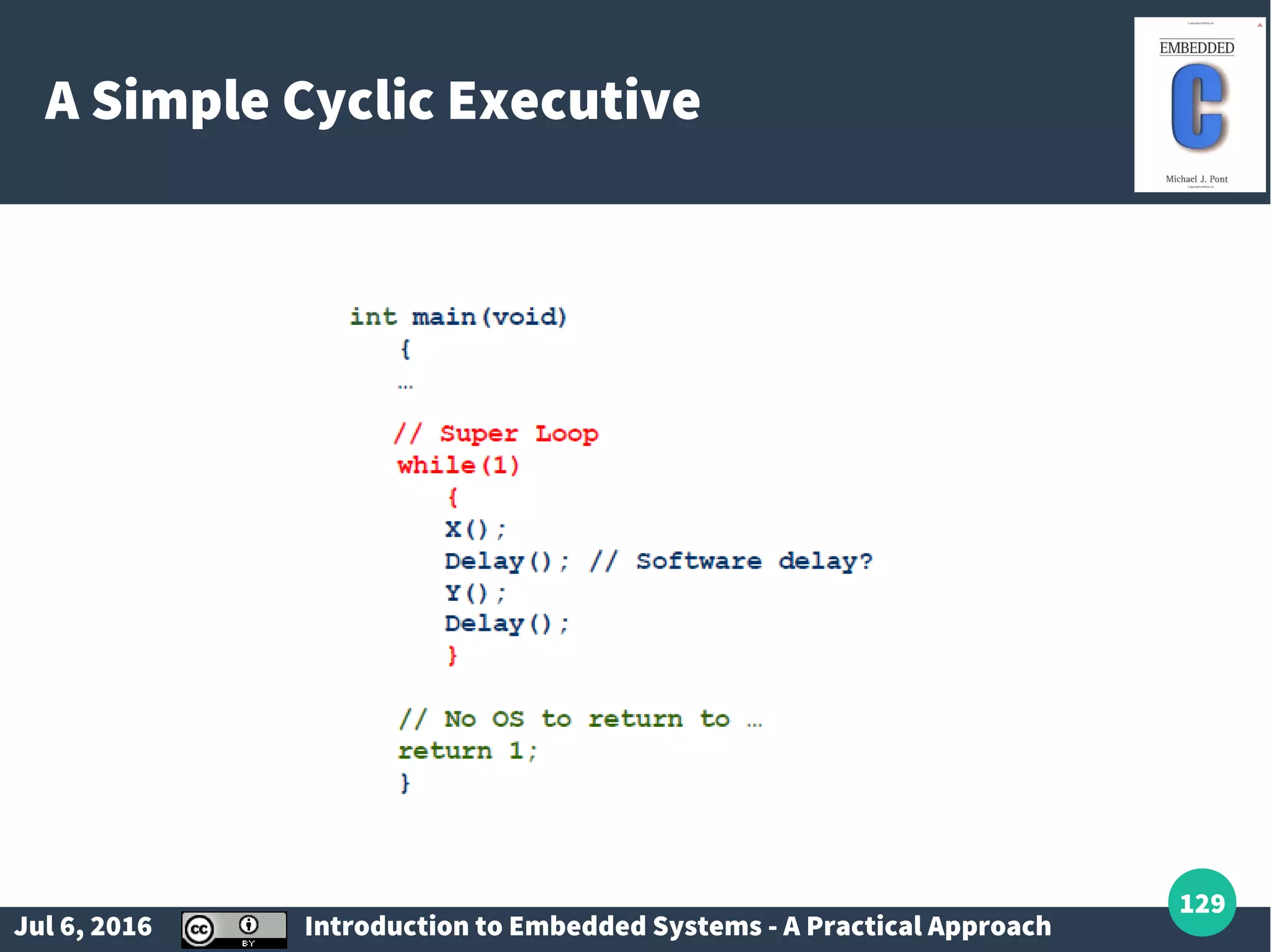
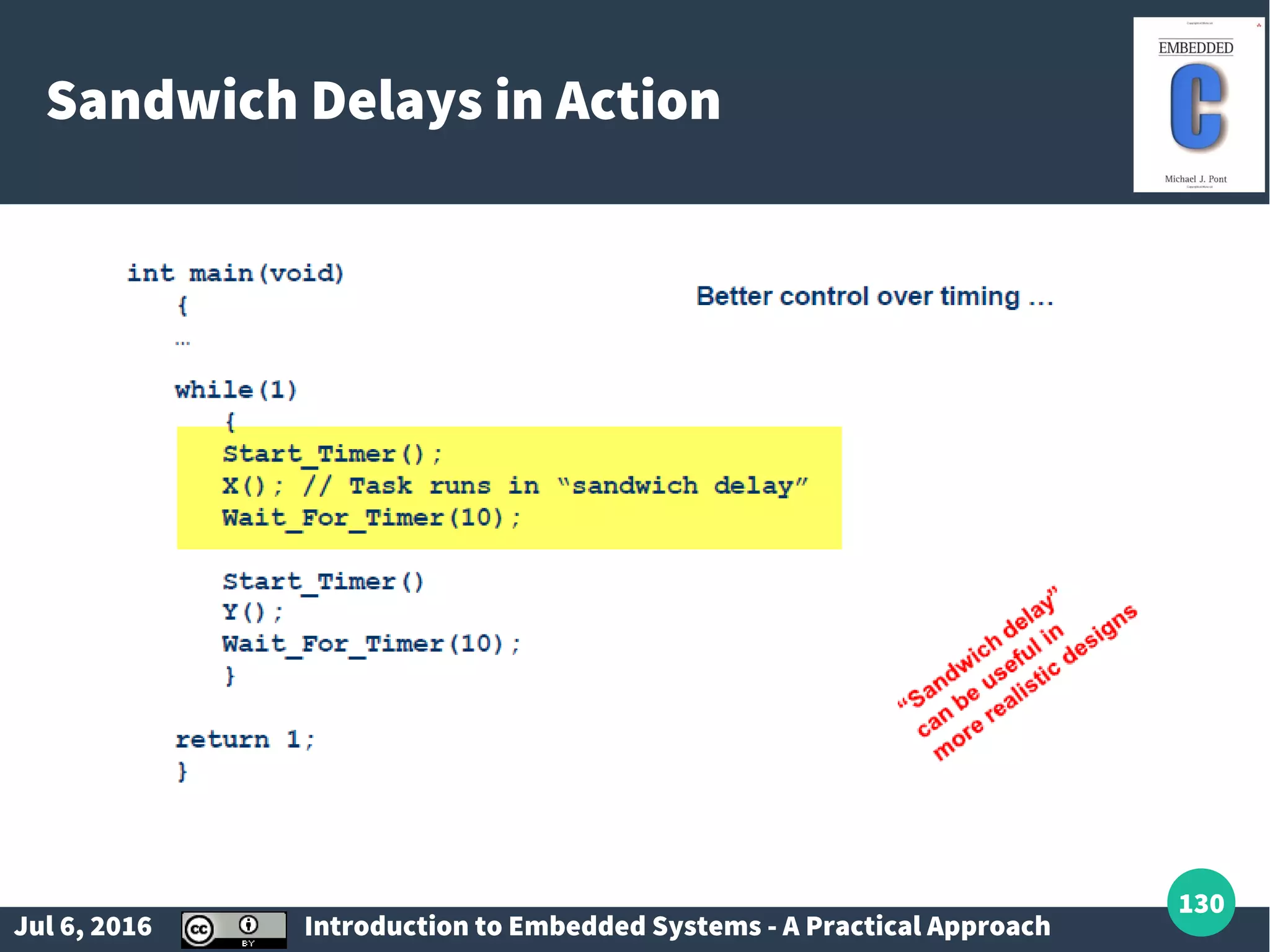
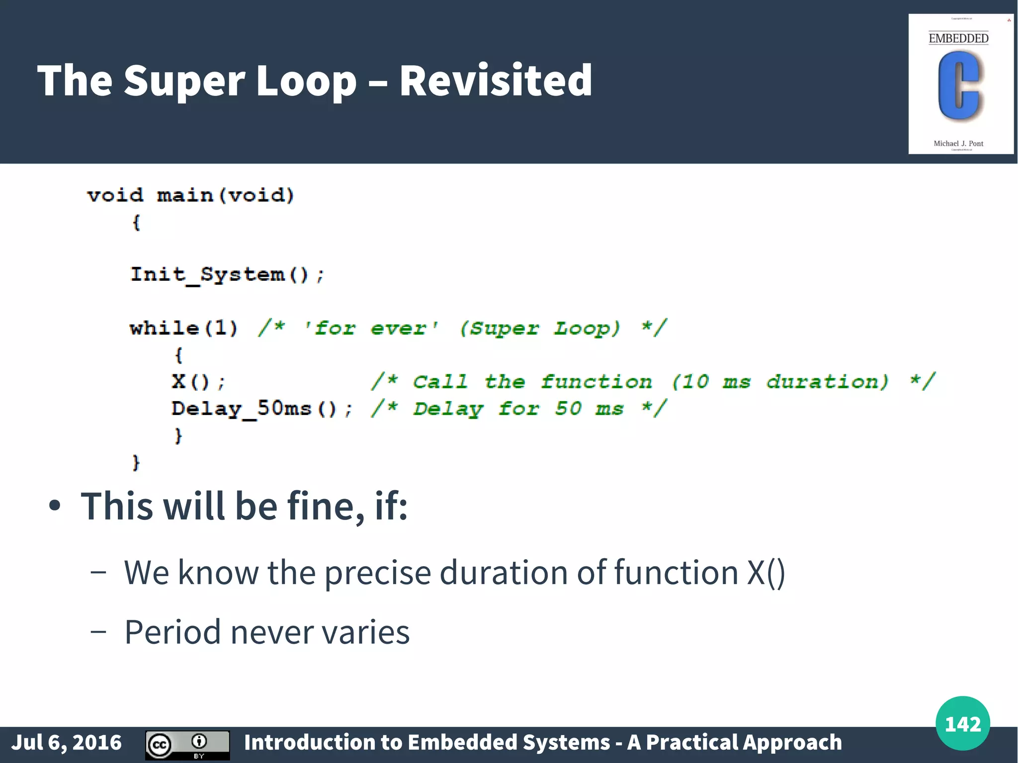
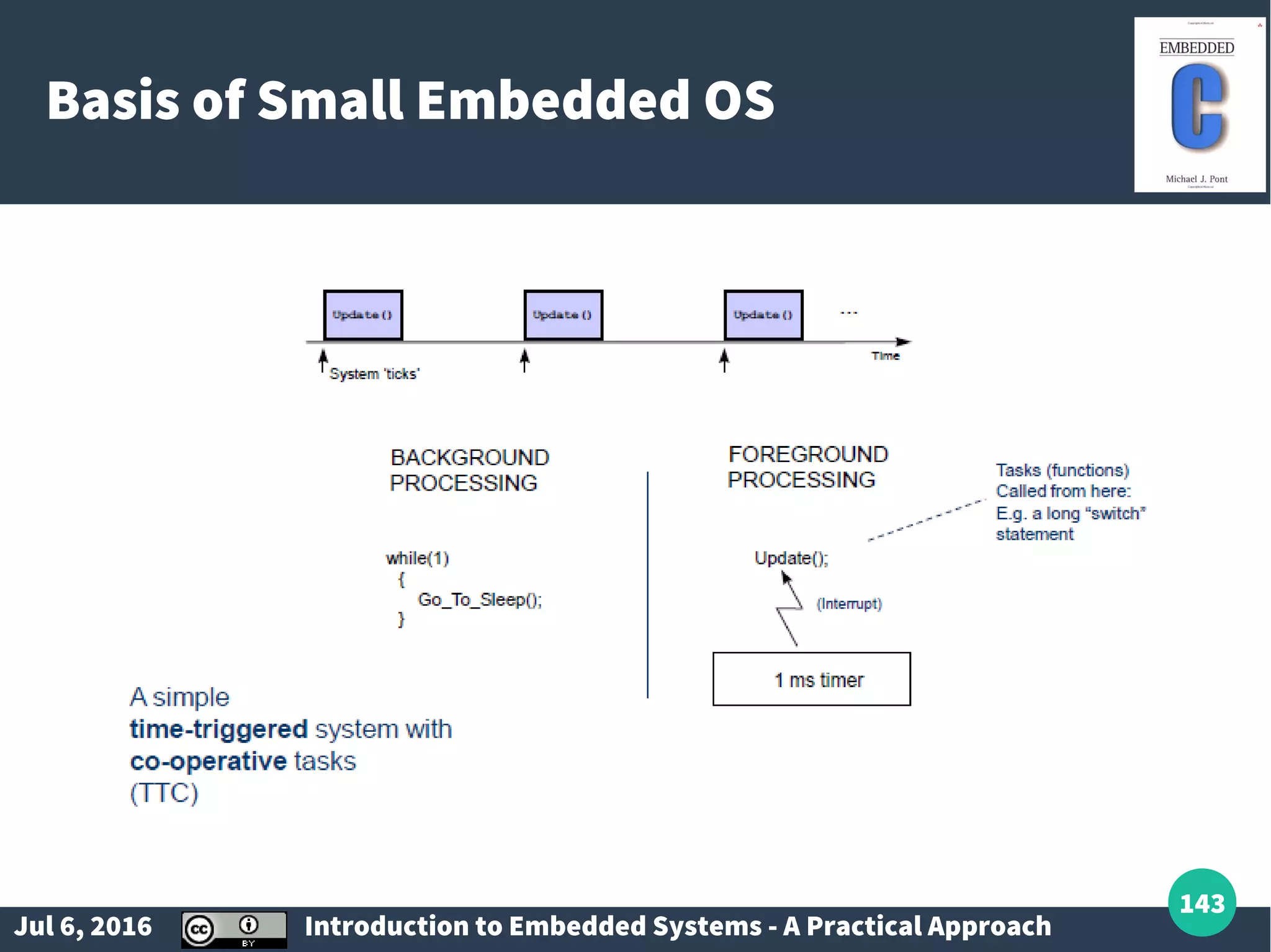
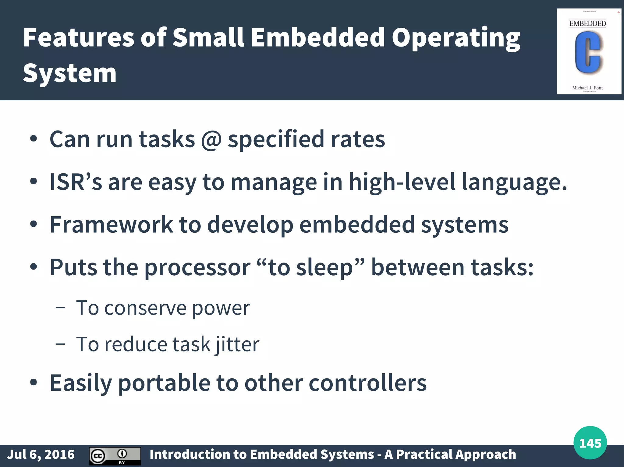
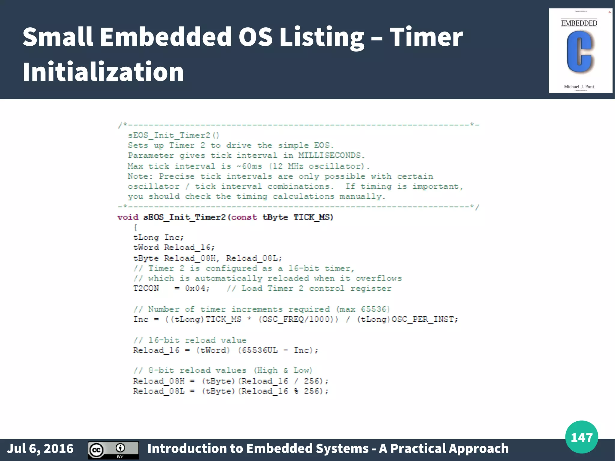
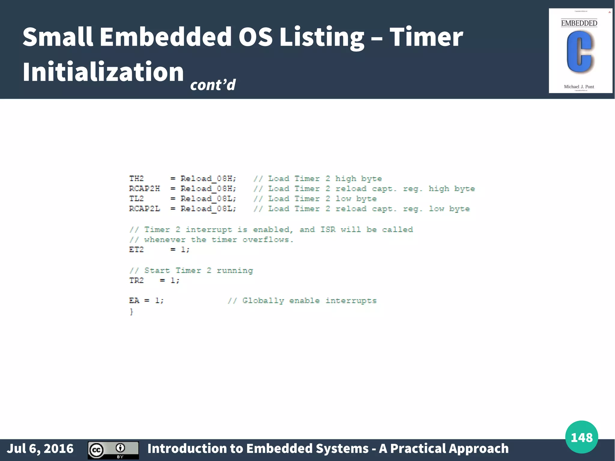
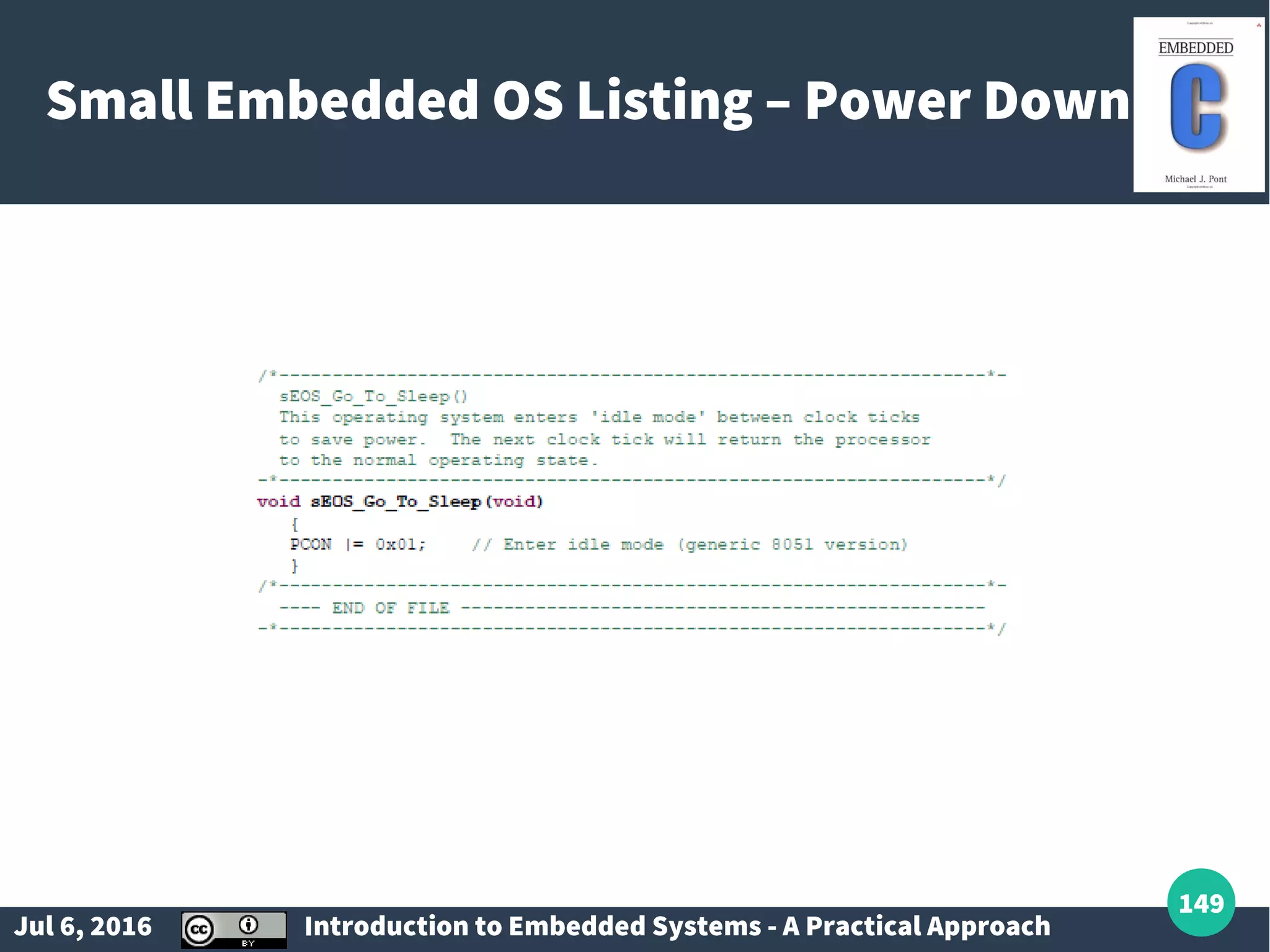
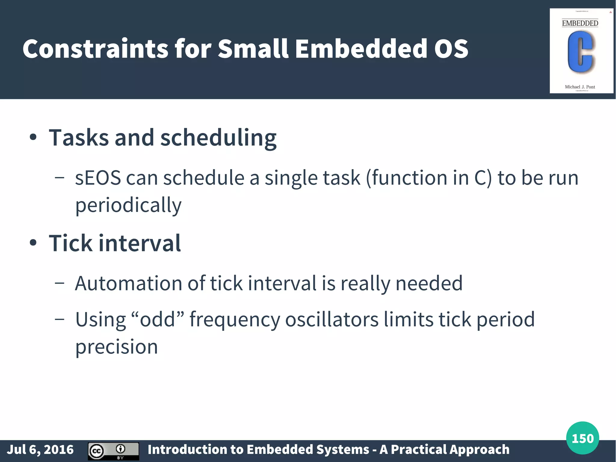
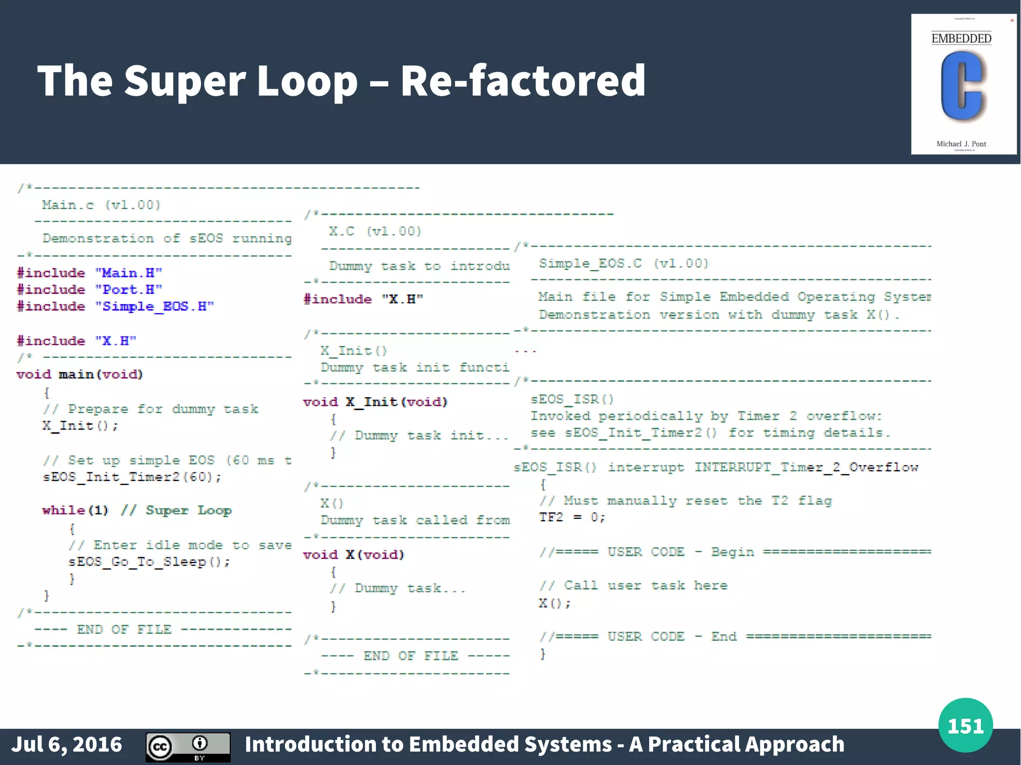
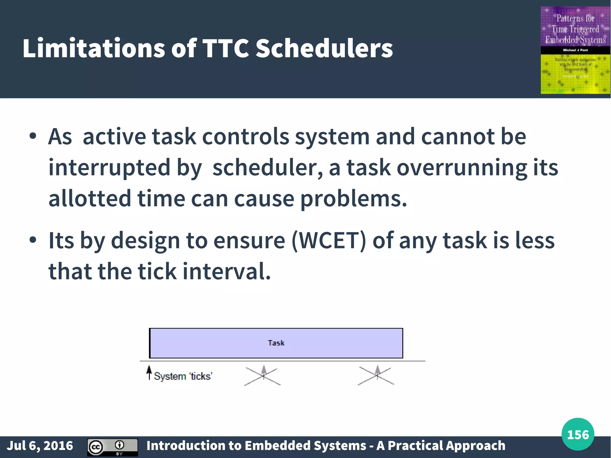
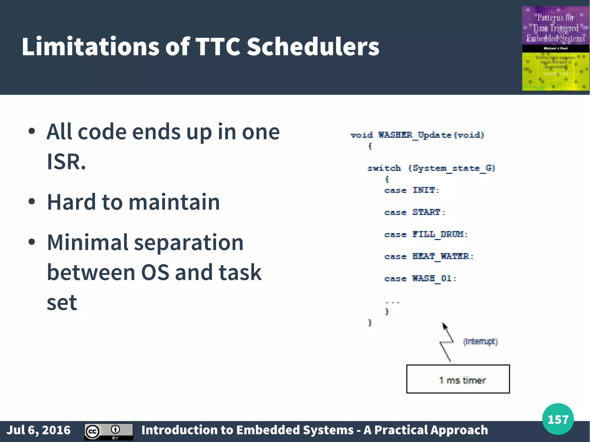
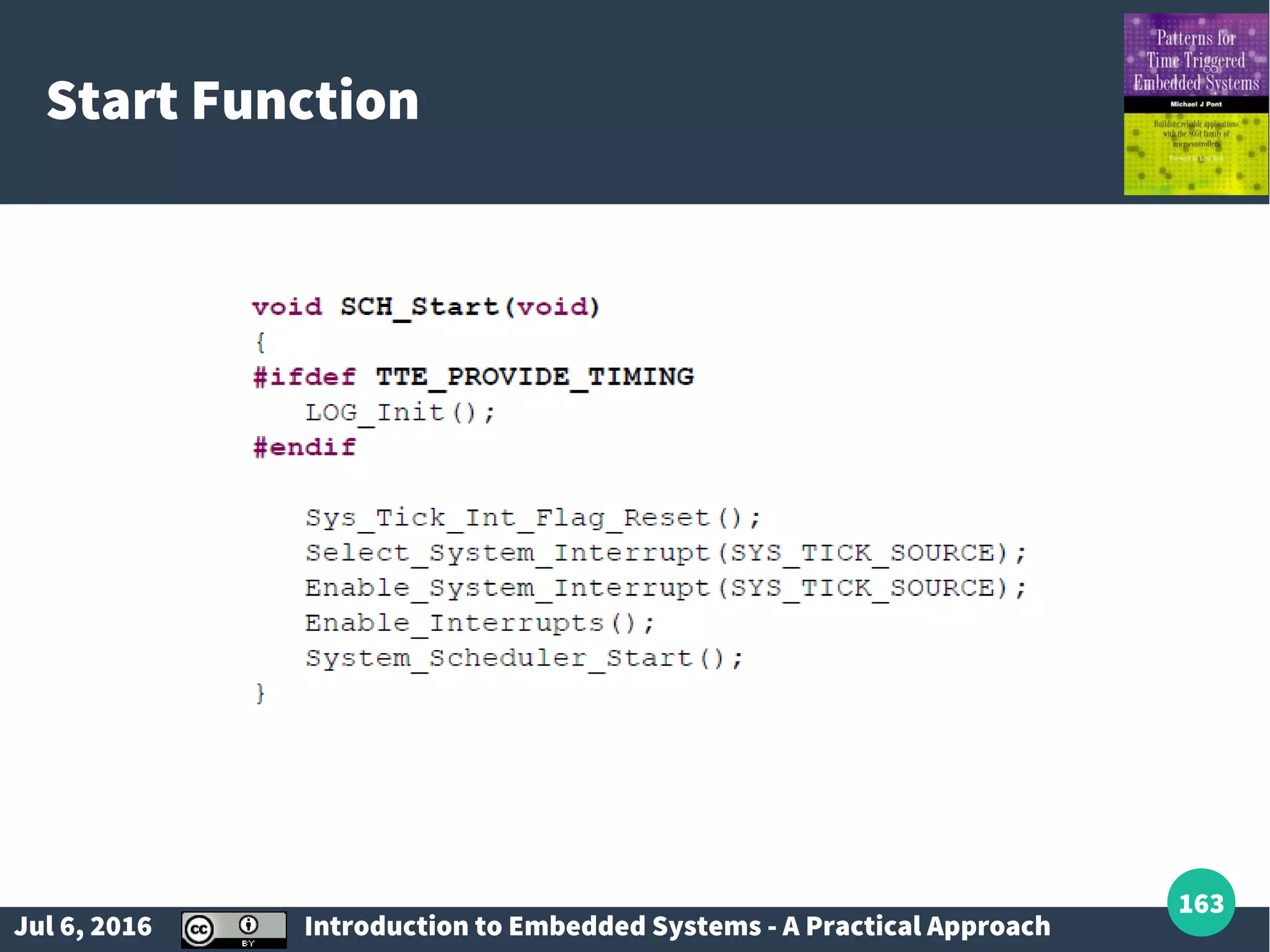
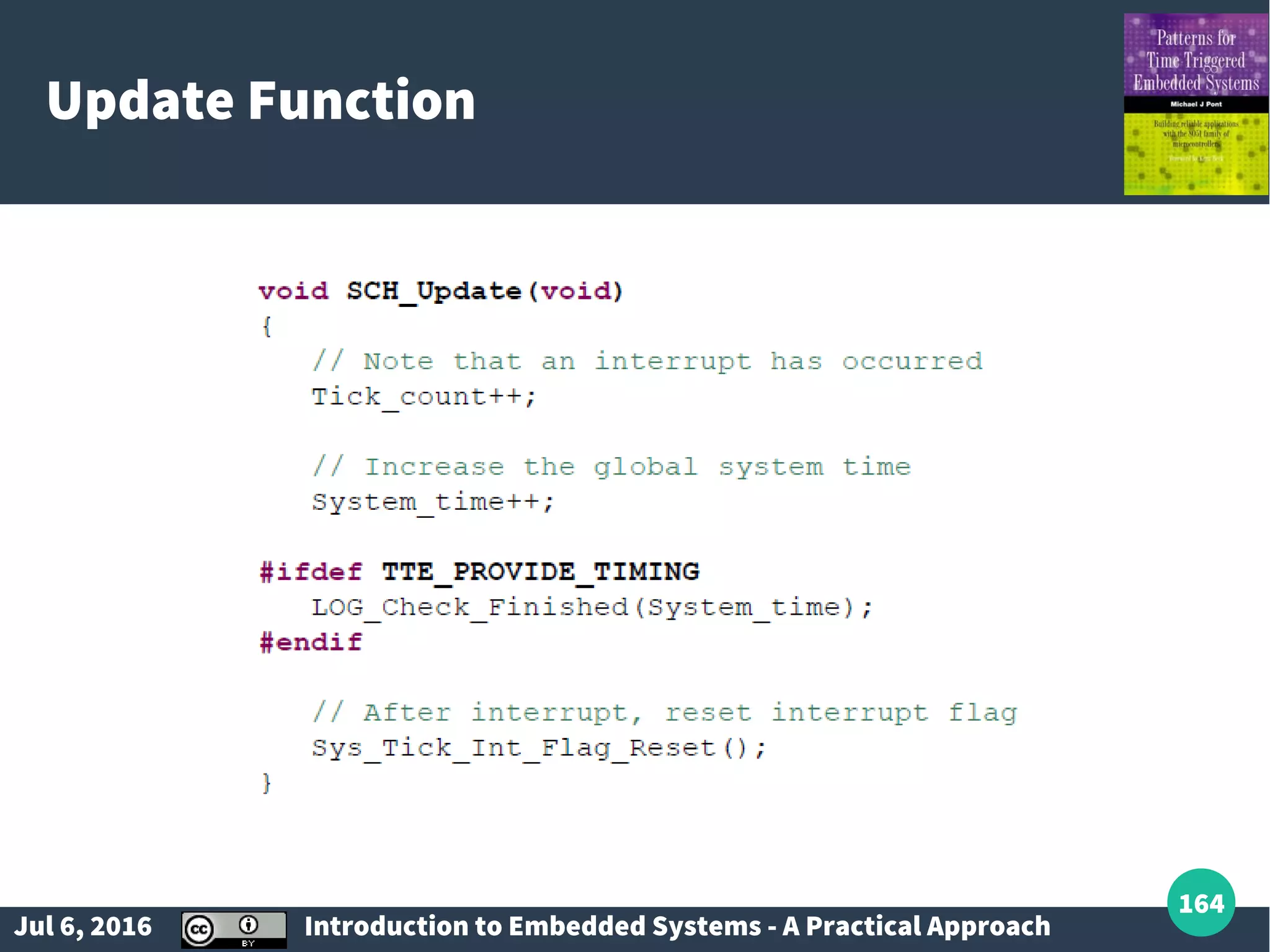
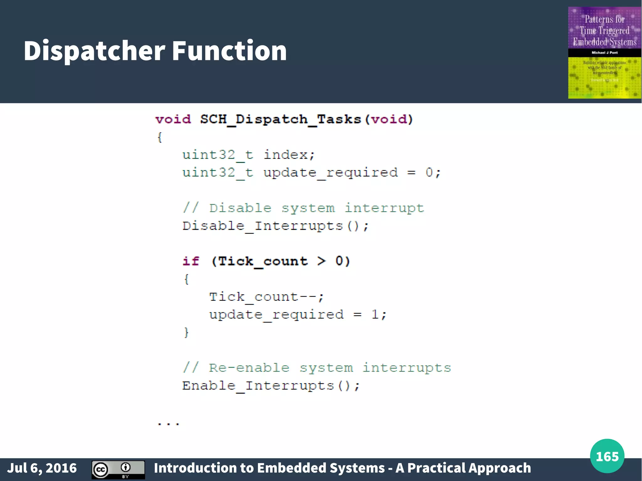
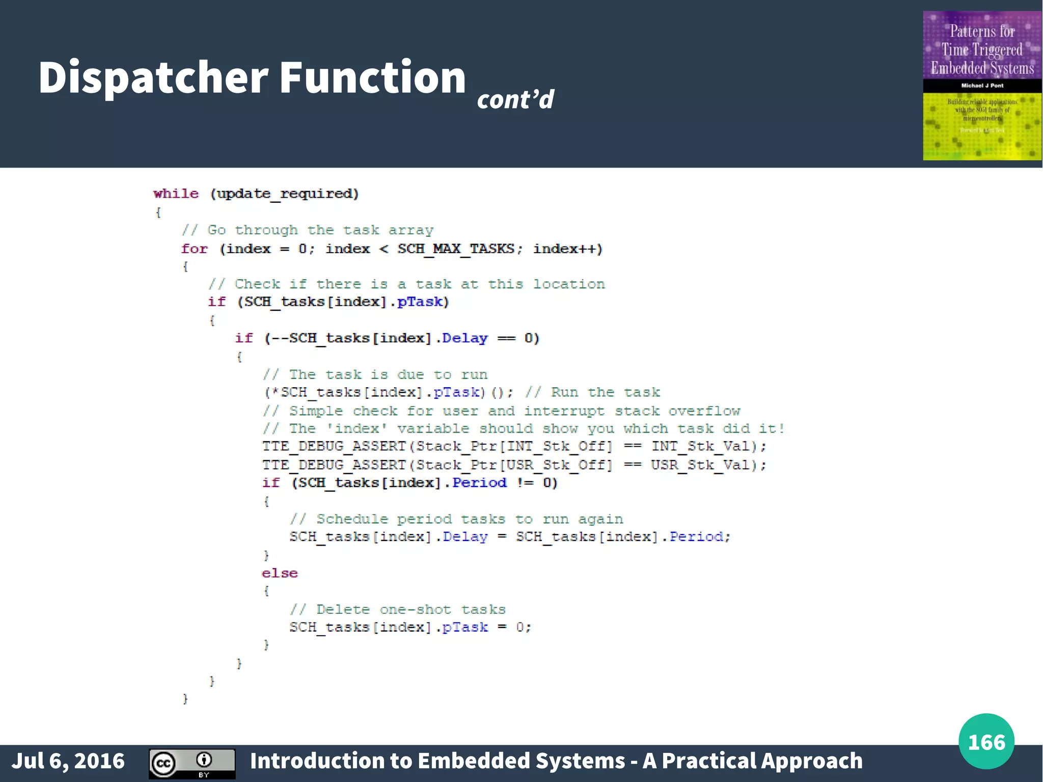
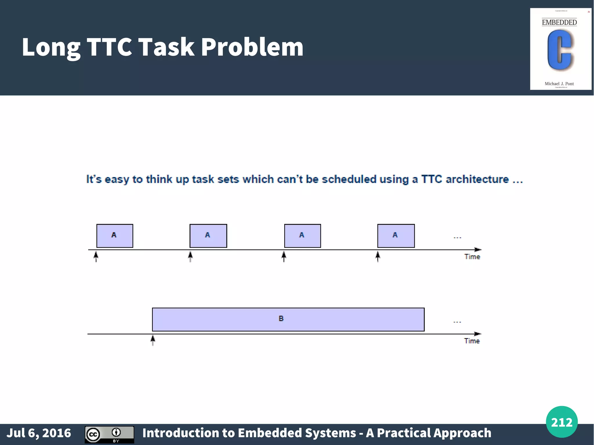
Discussion on hardware and software timeout mechanisms, with an emphasis on the development of small embedded OS.
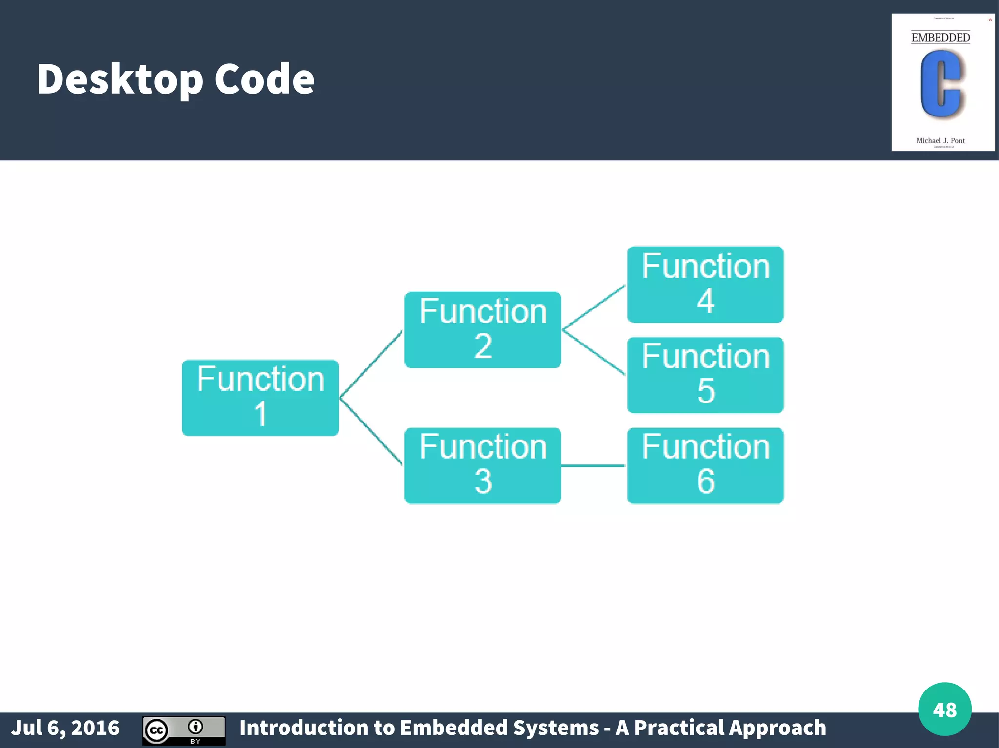
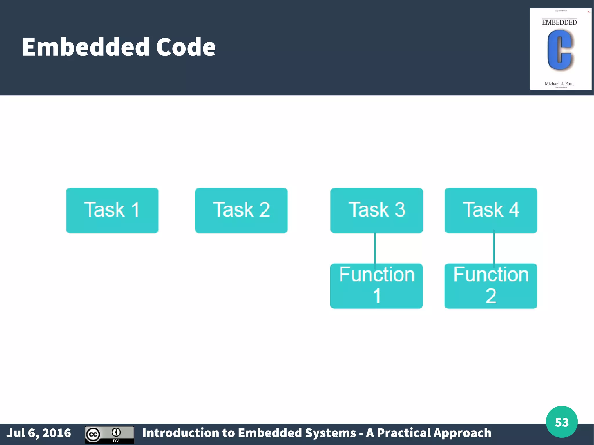
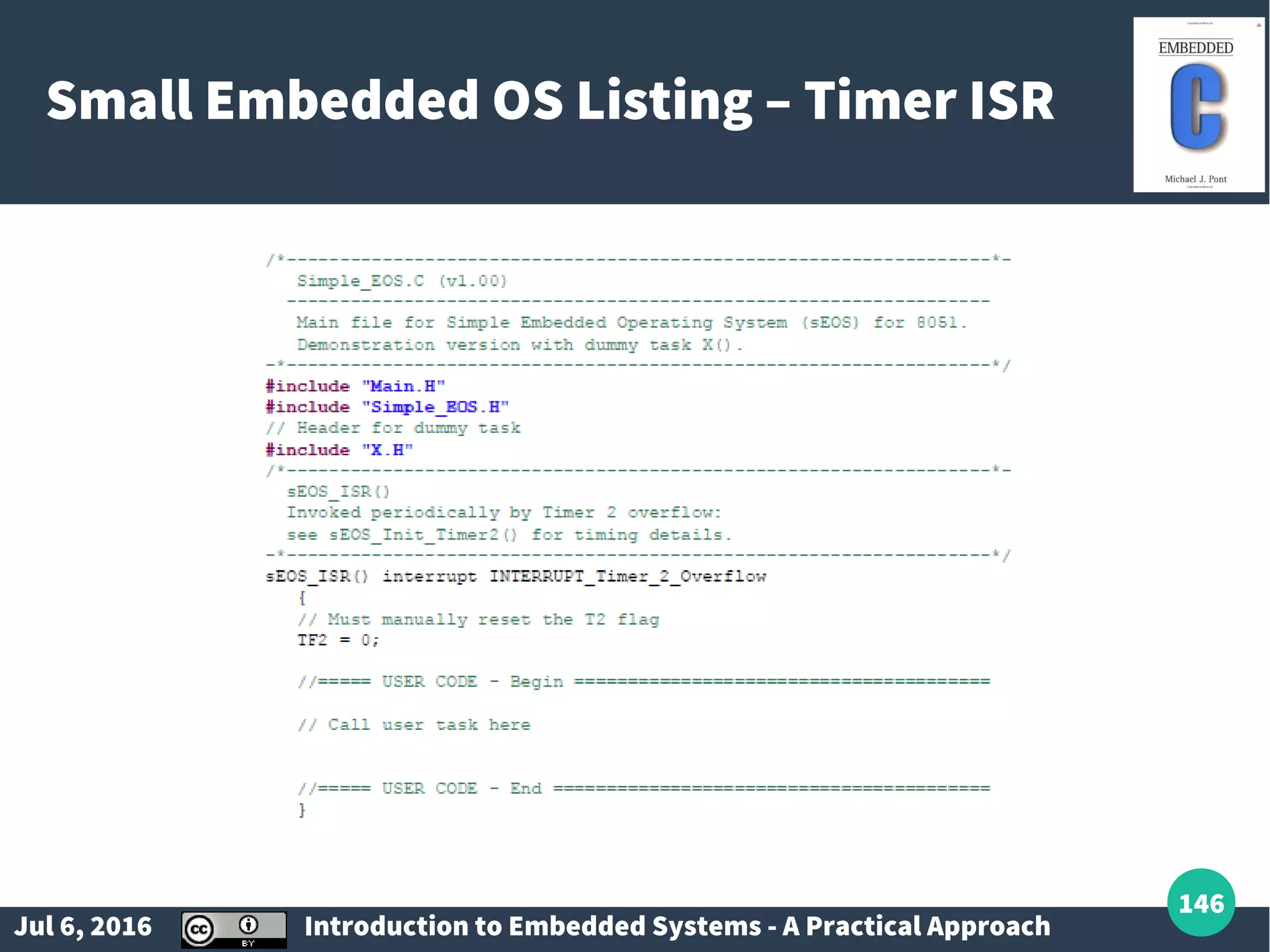
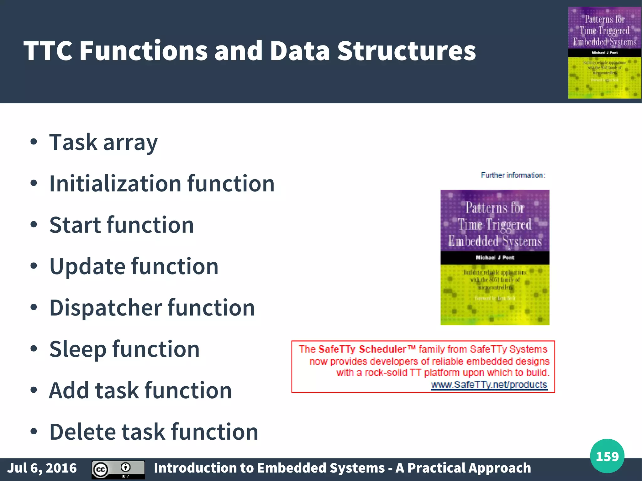
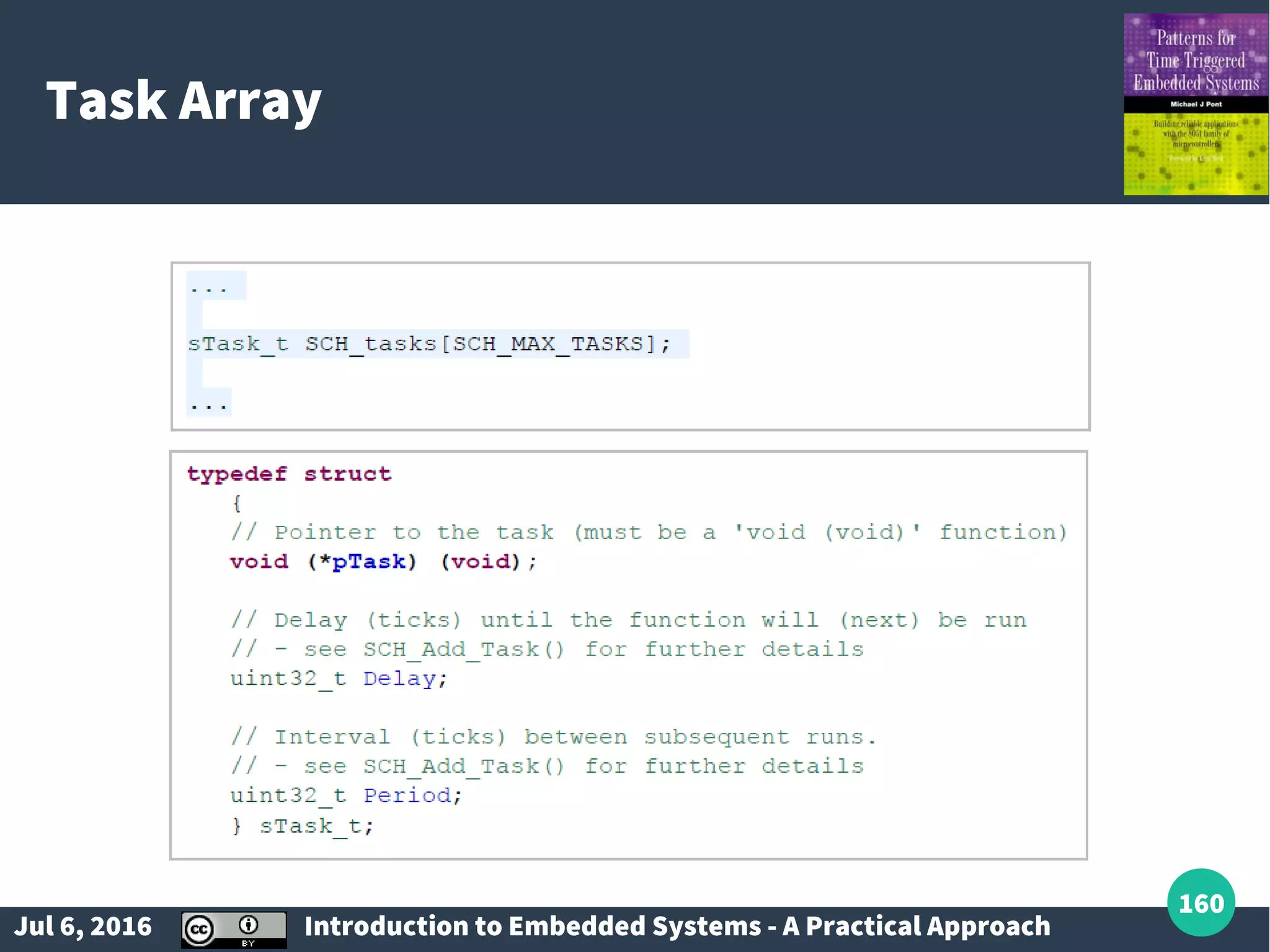
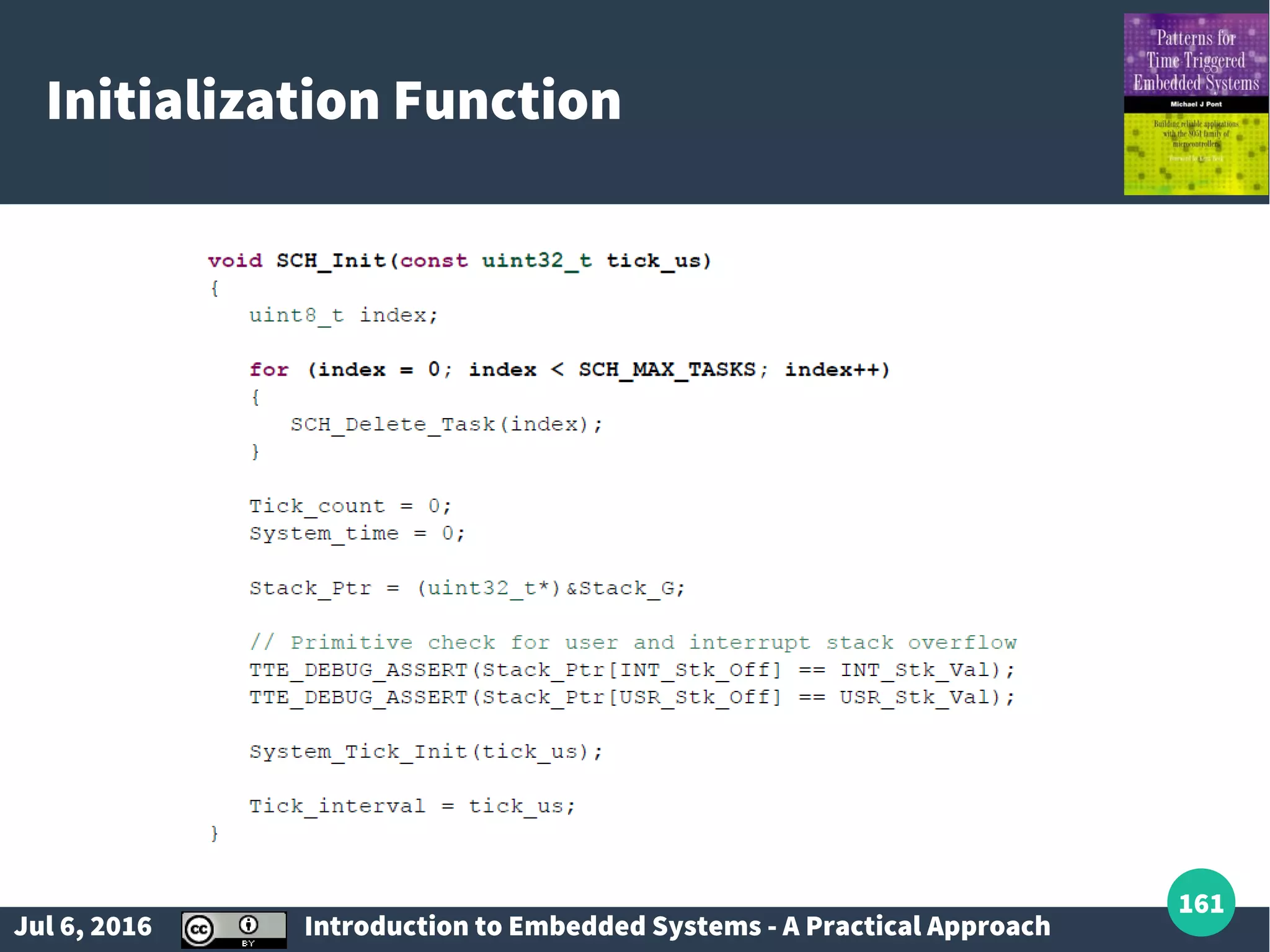
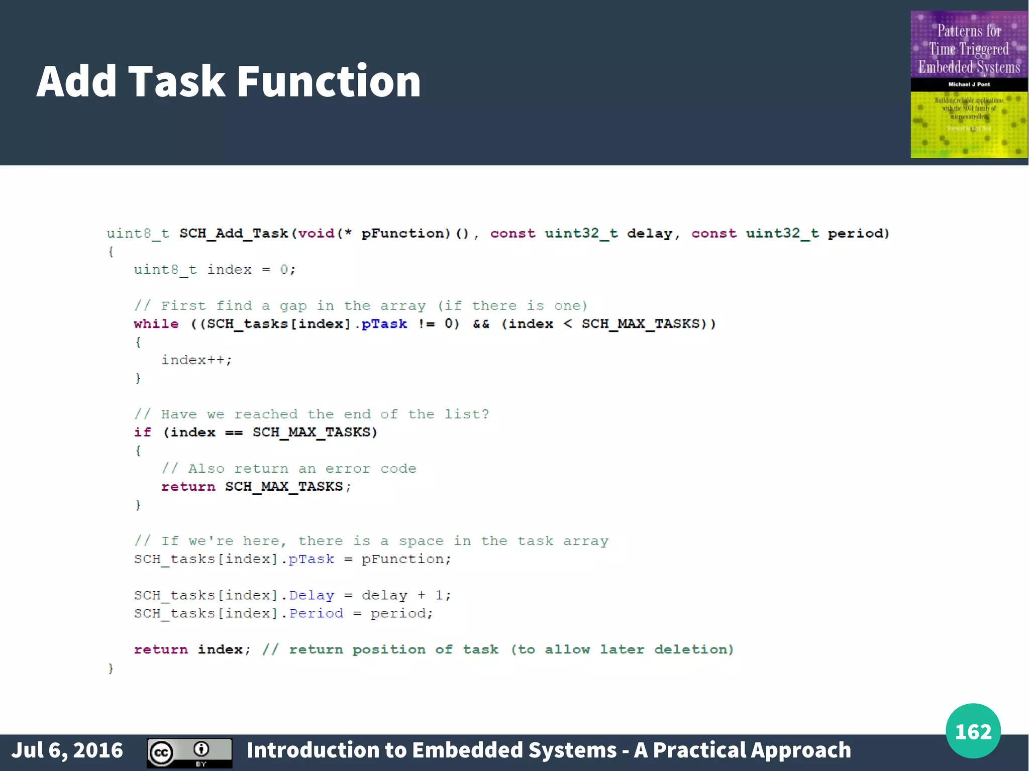
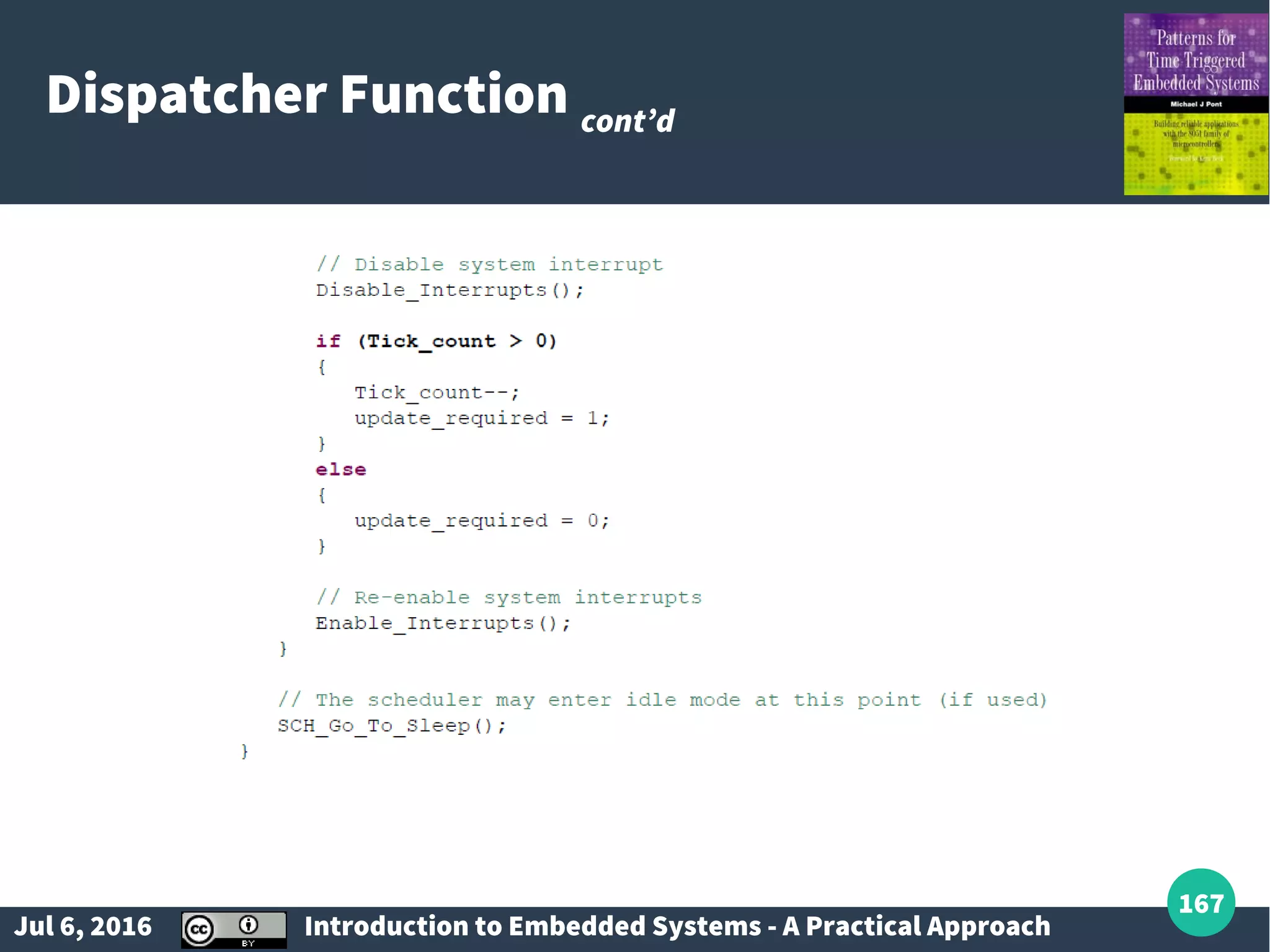
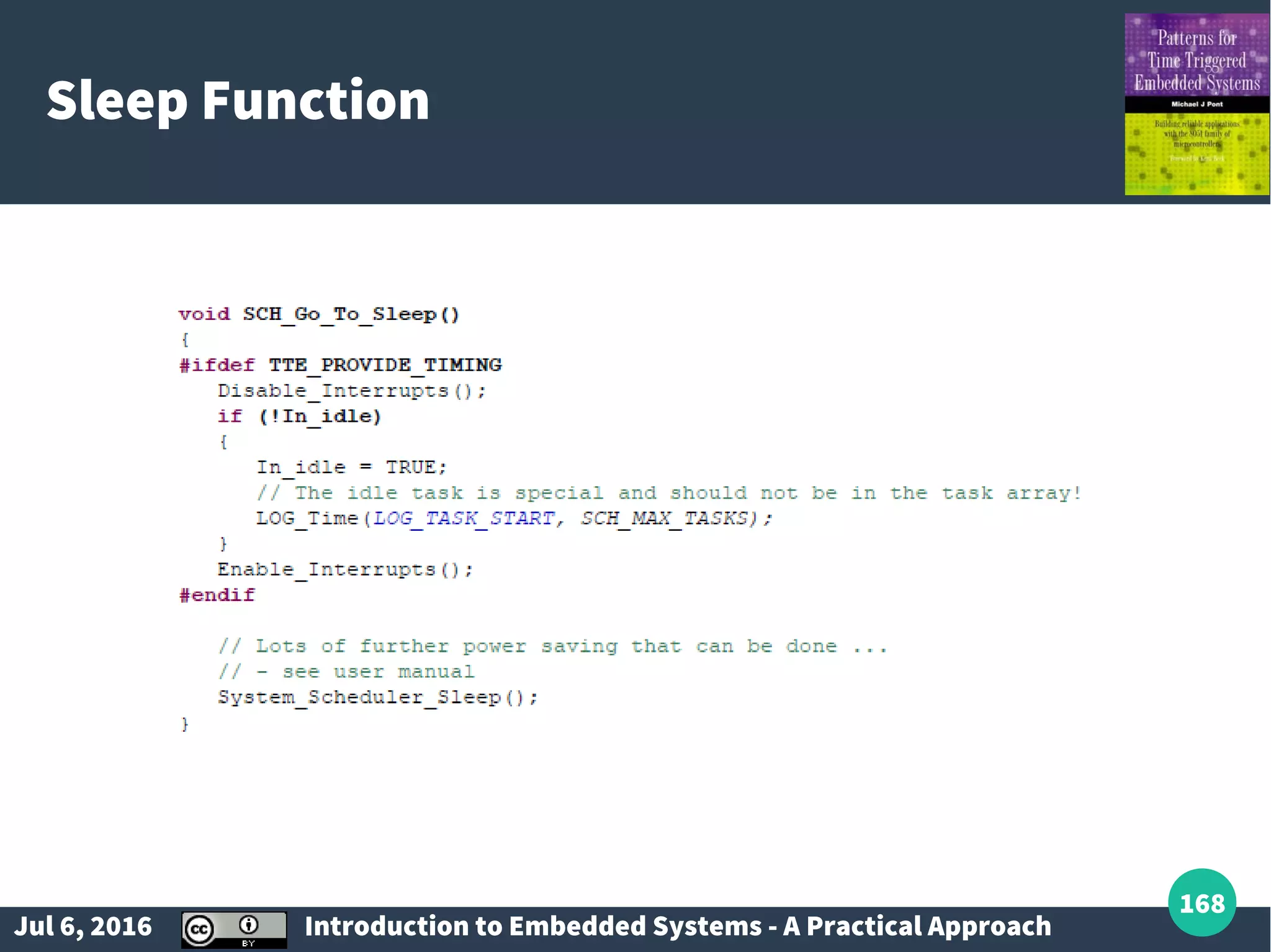
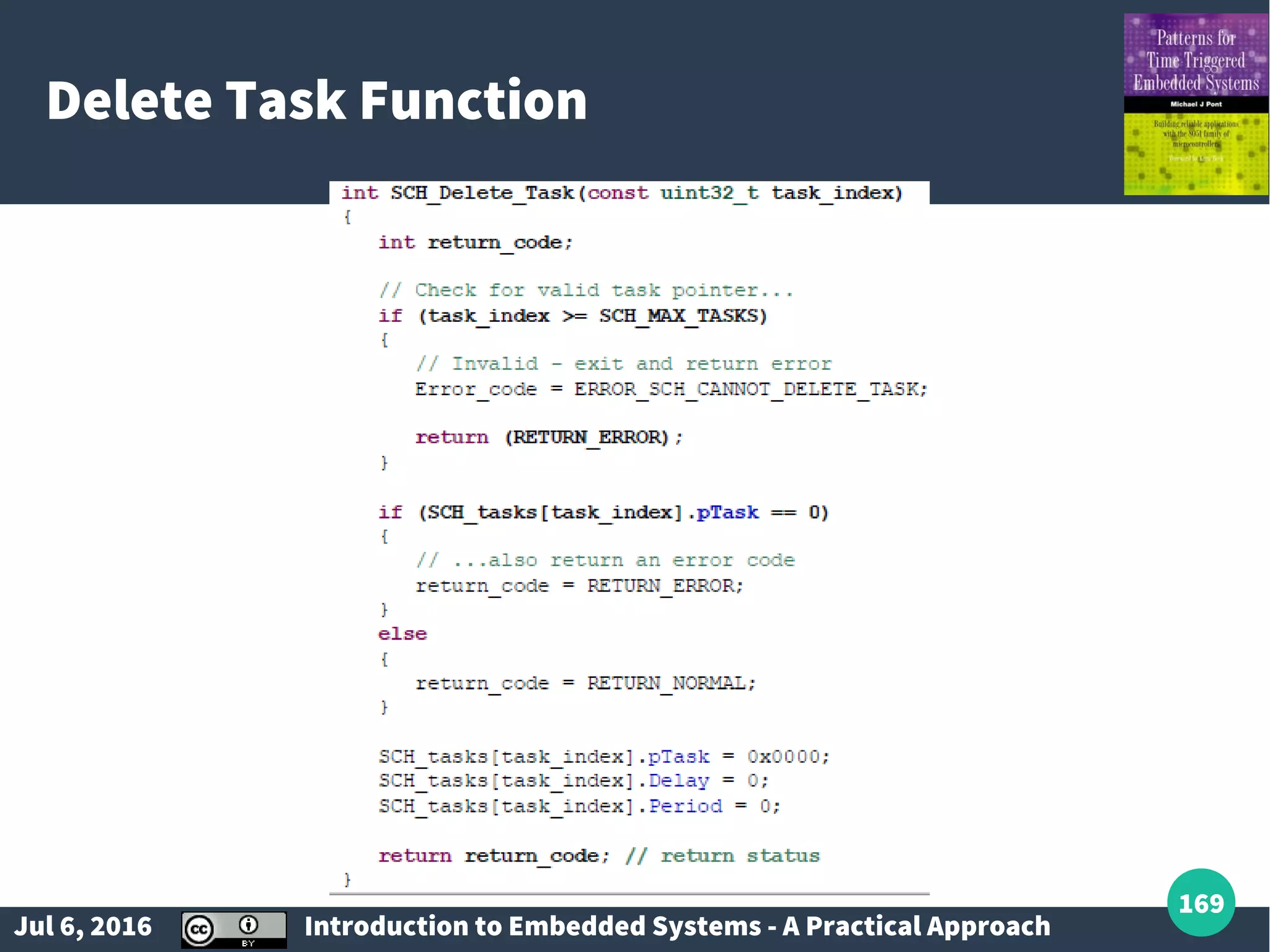
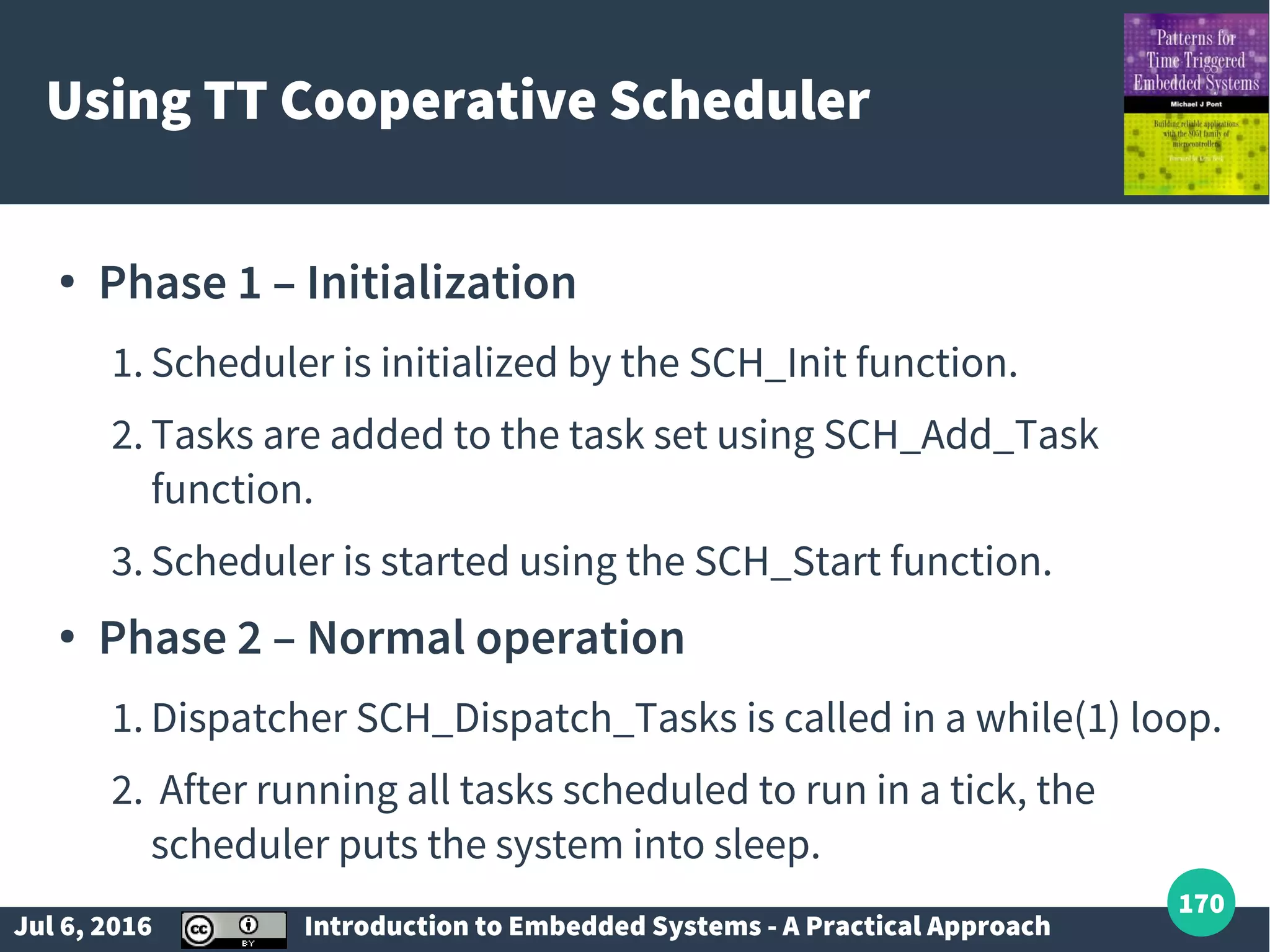
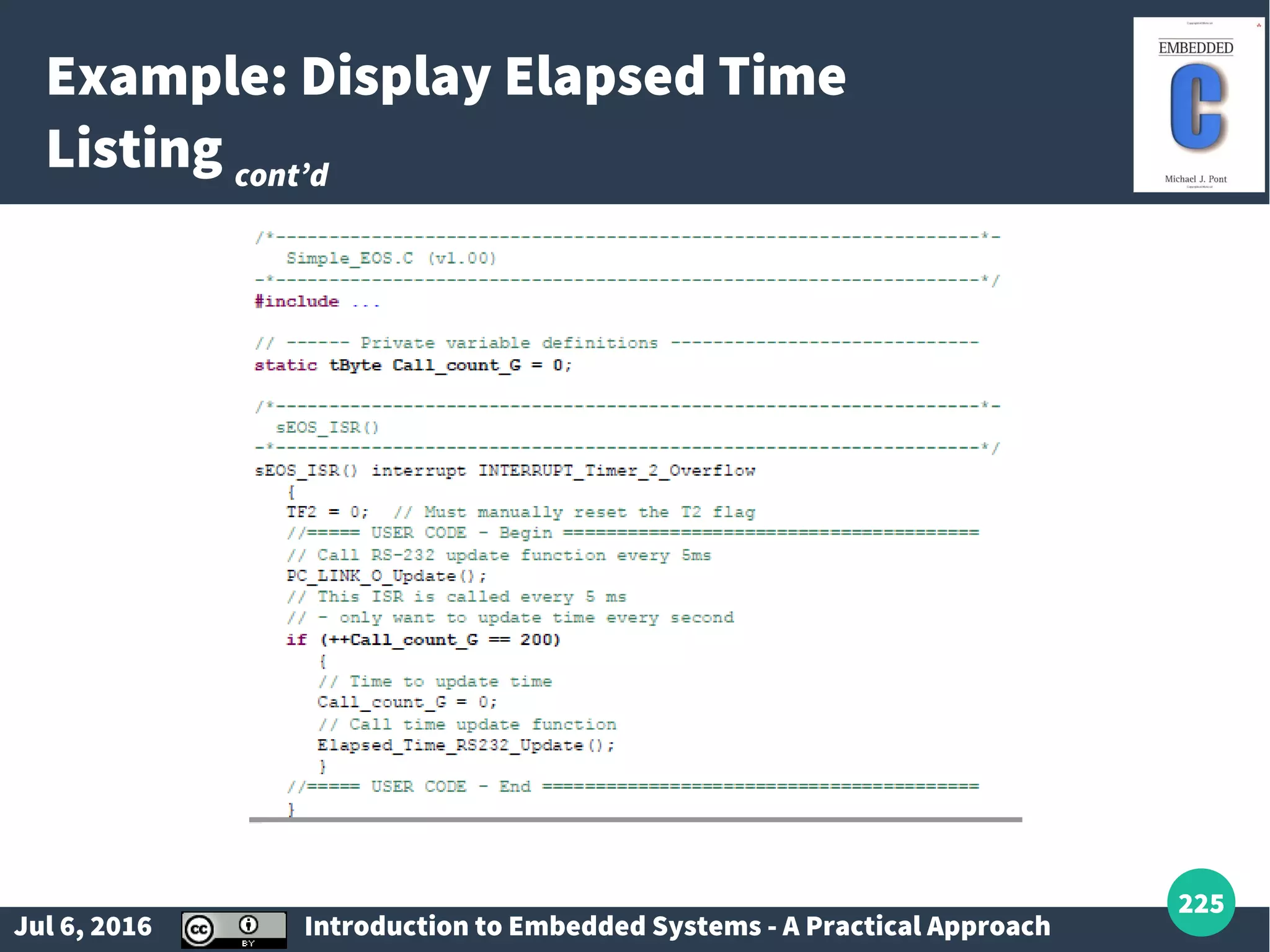
Listing tasks and functions for managing scheduling in a small embedded operating system.
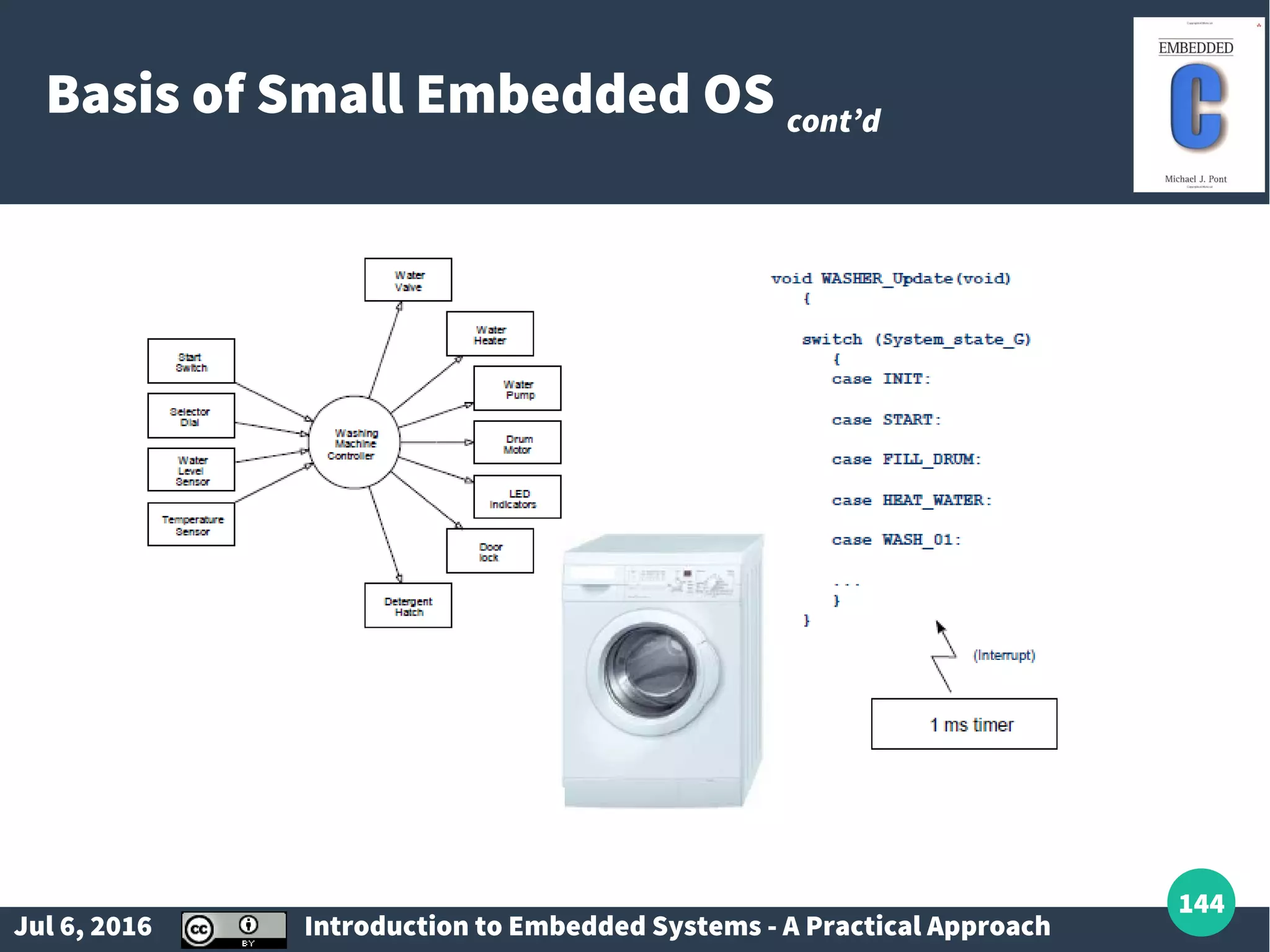
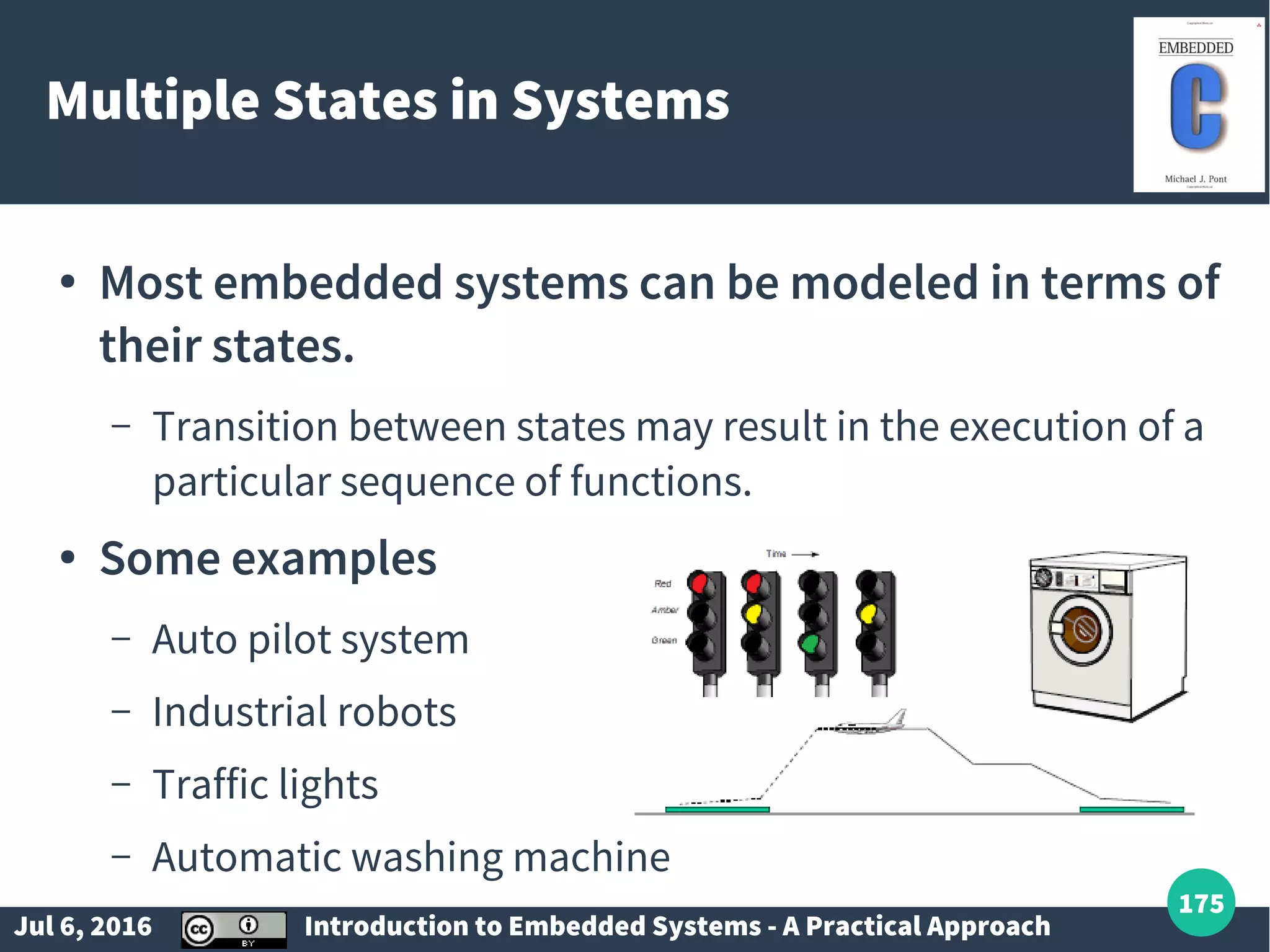
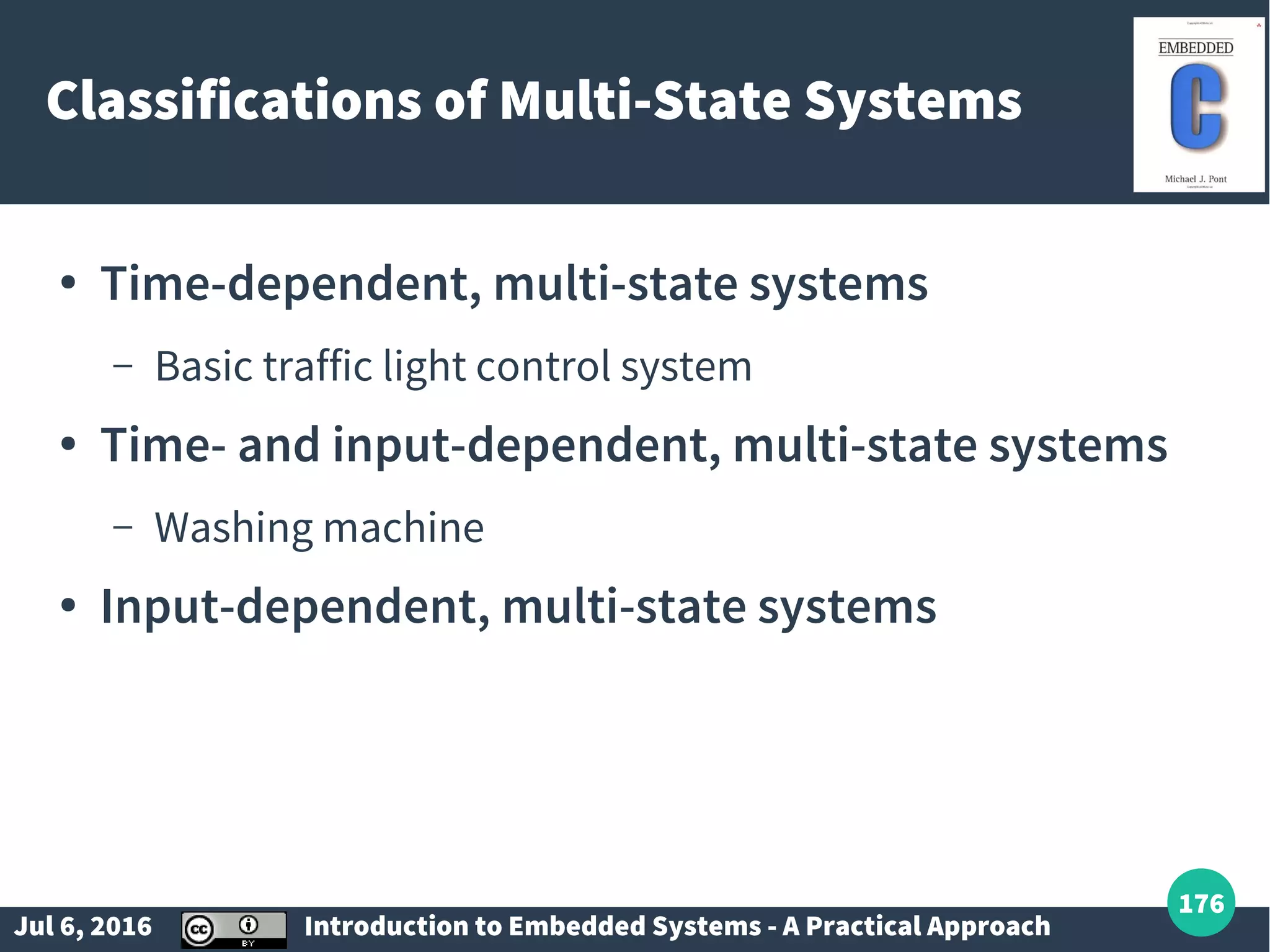
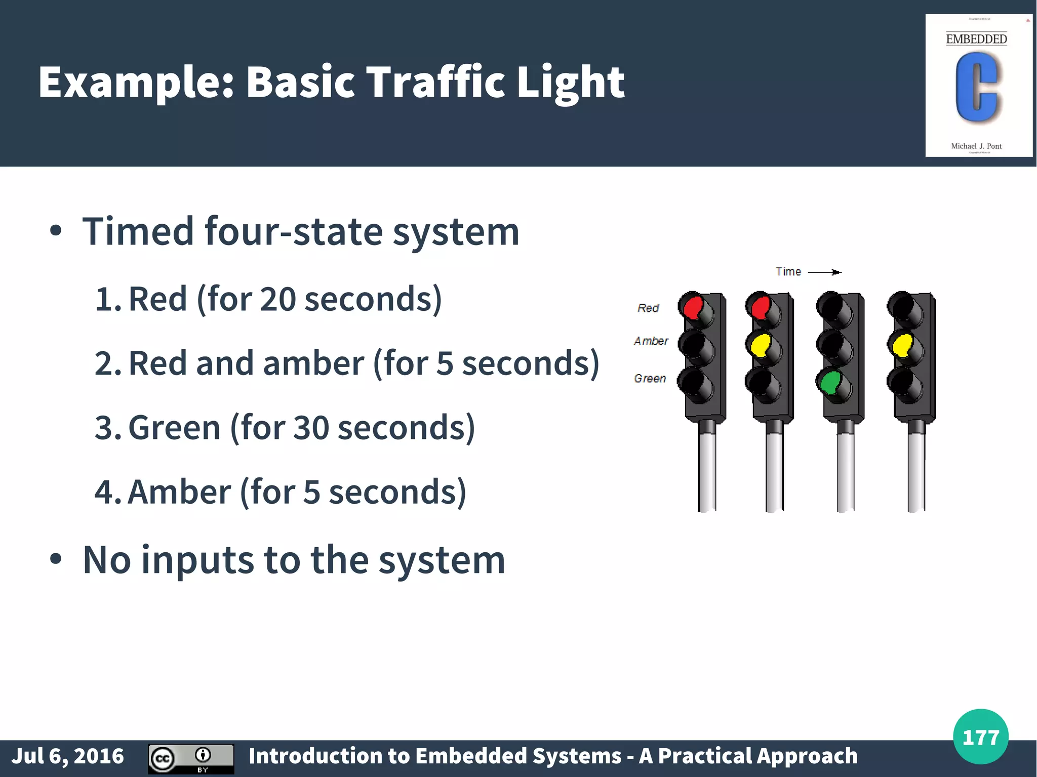
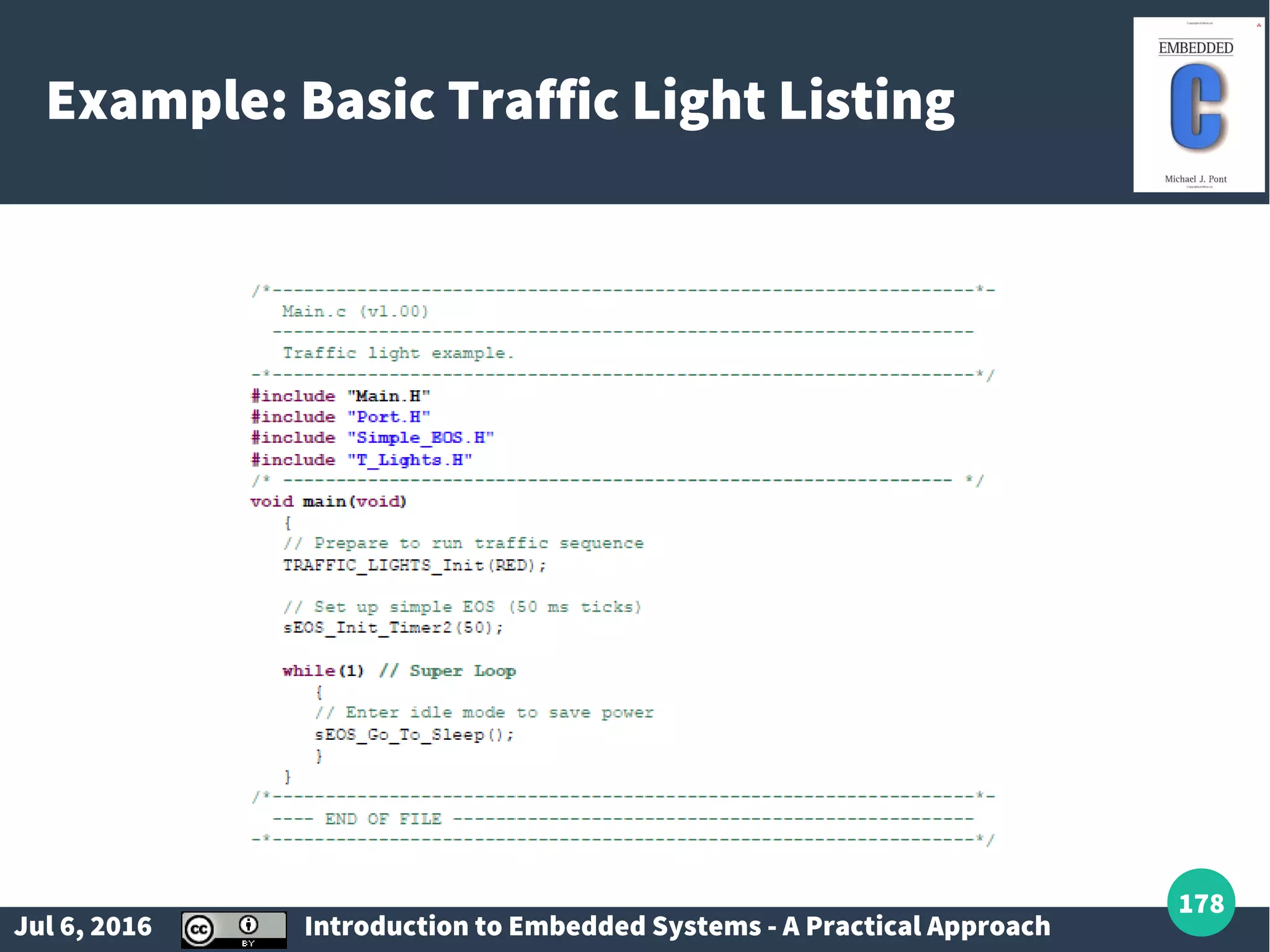
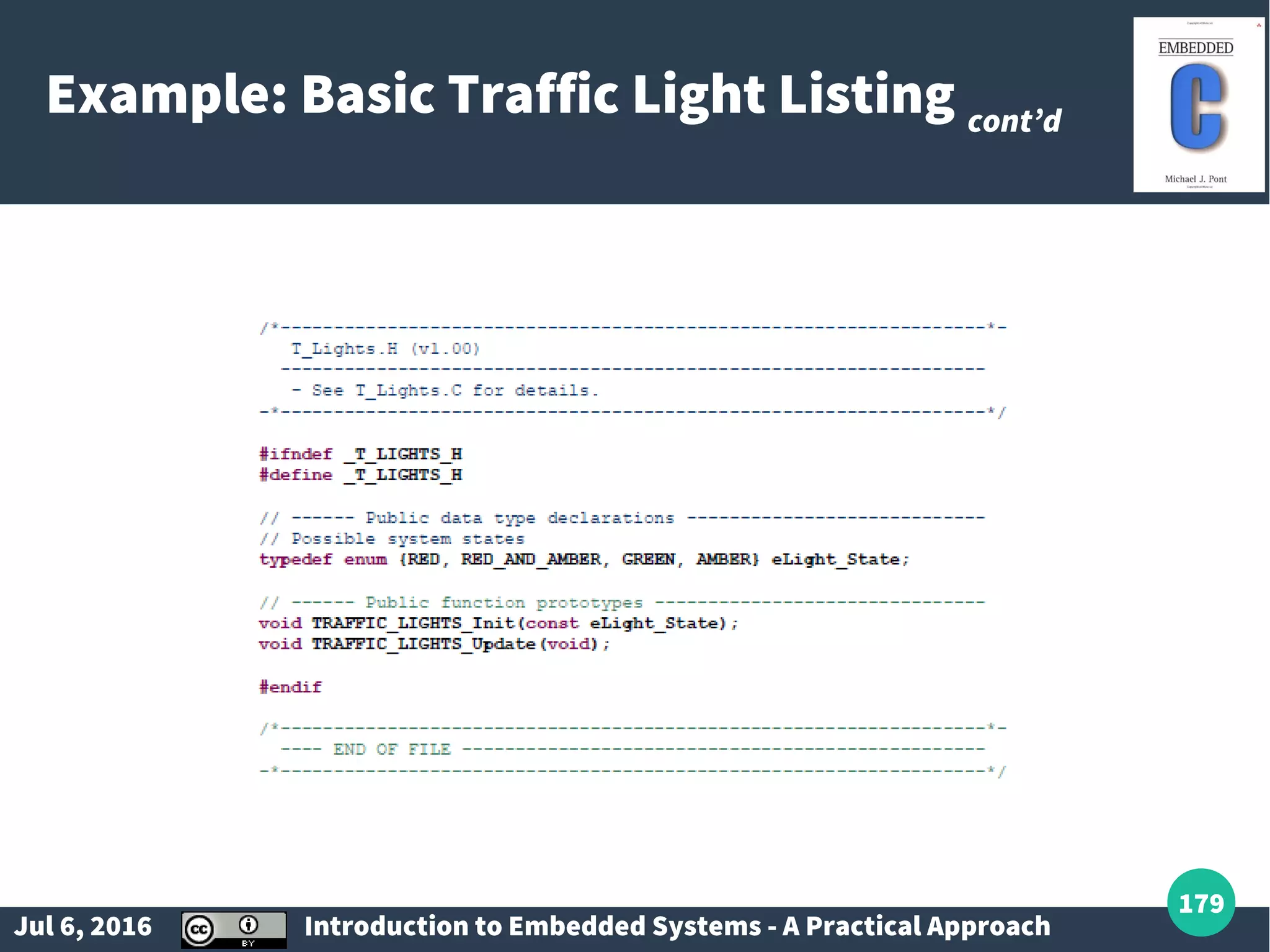
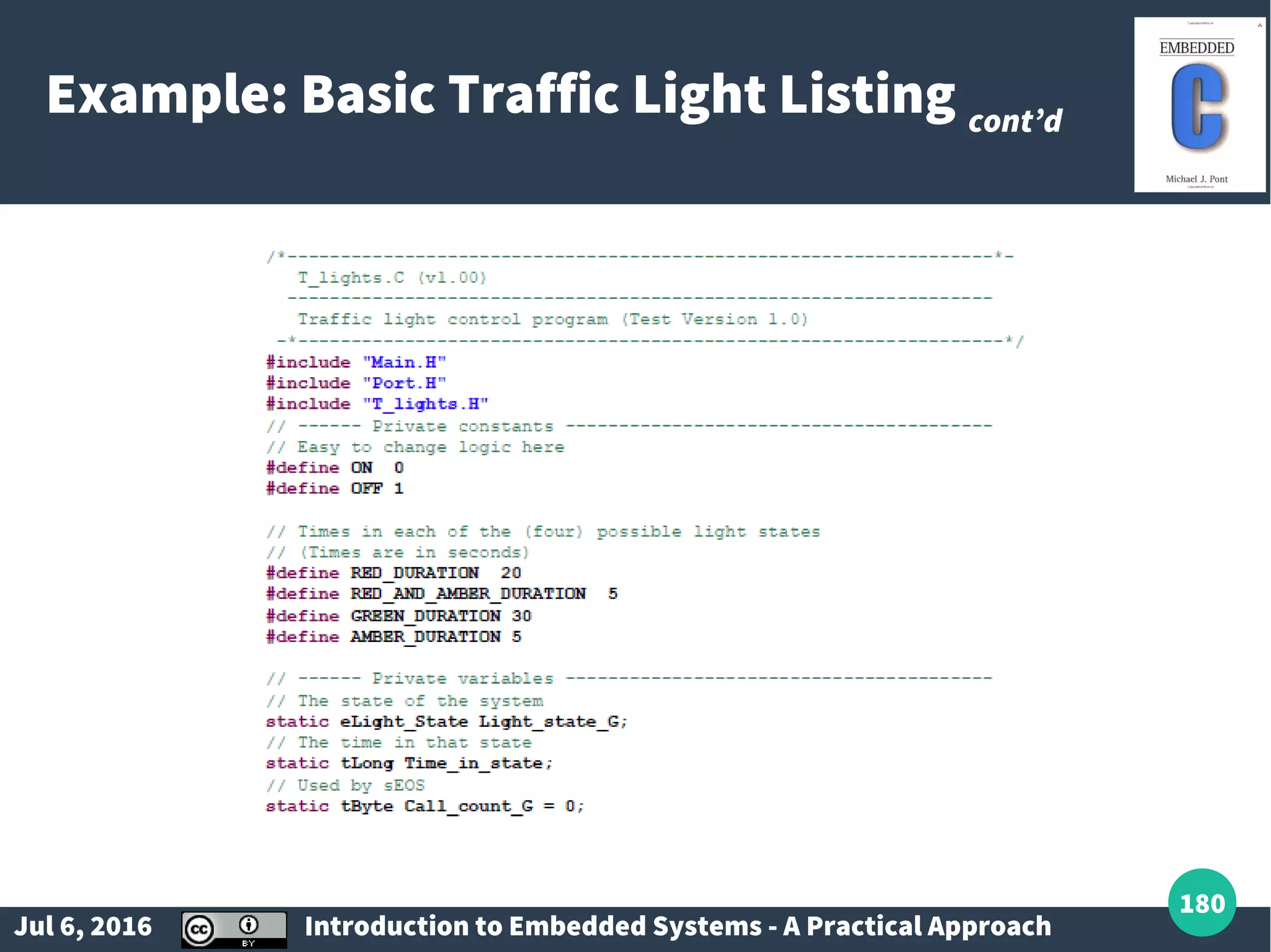
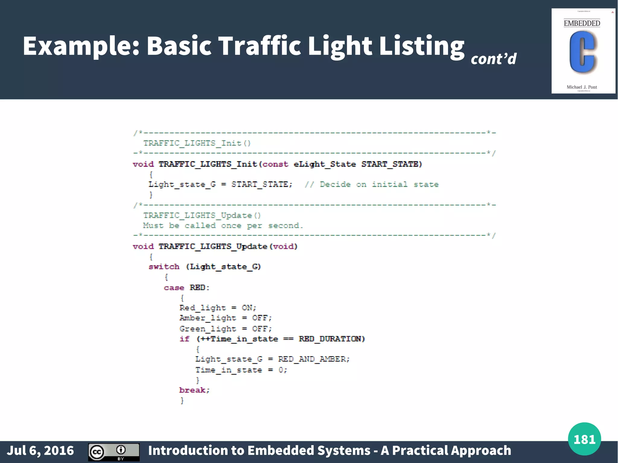
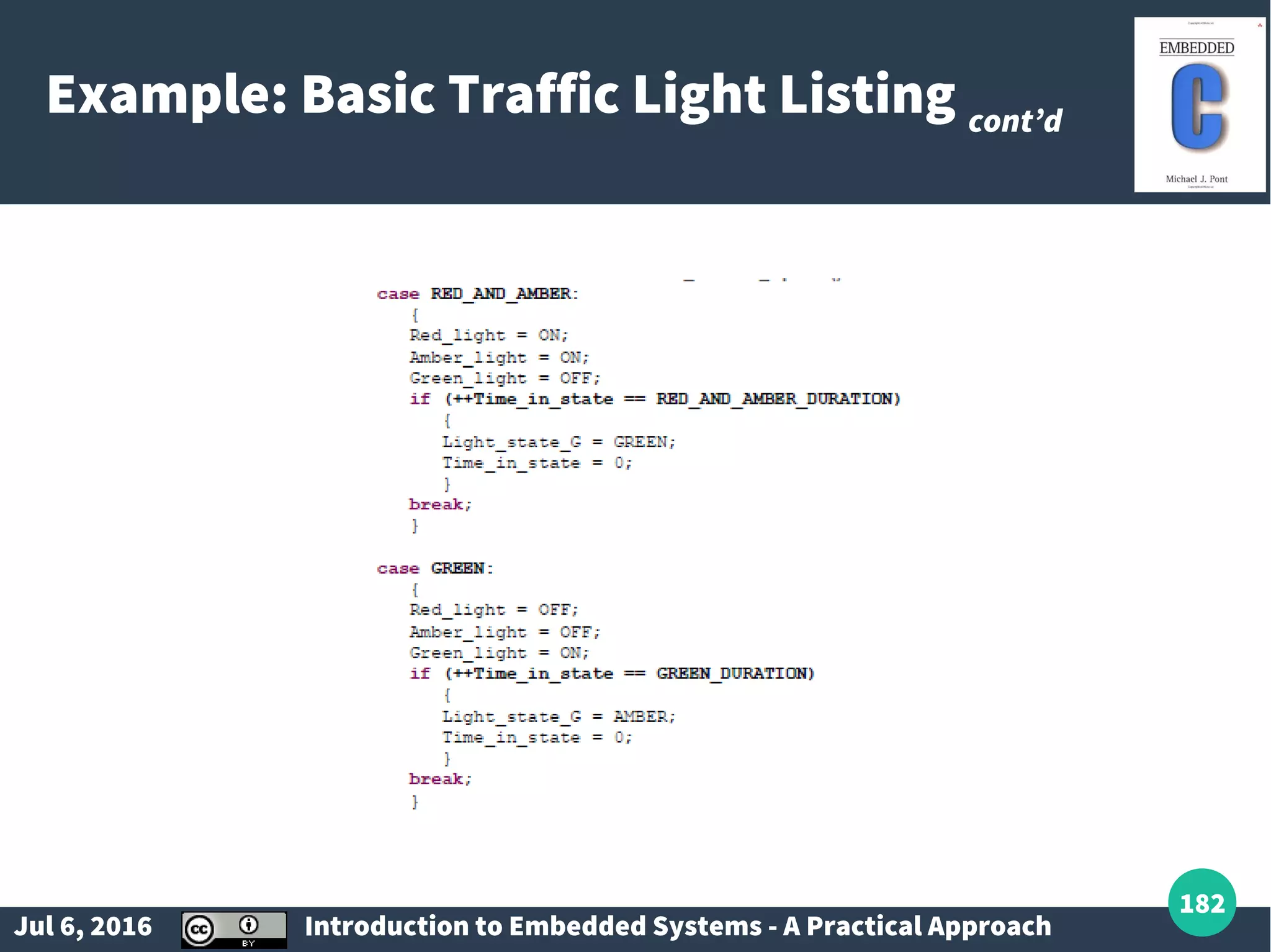
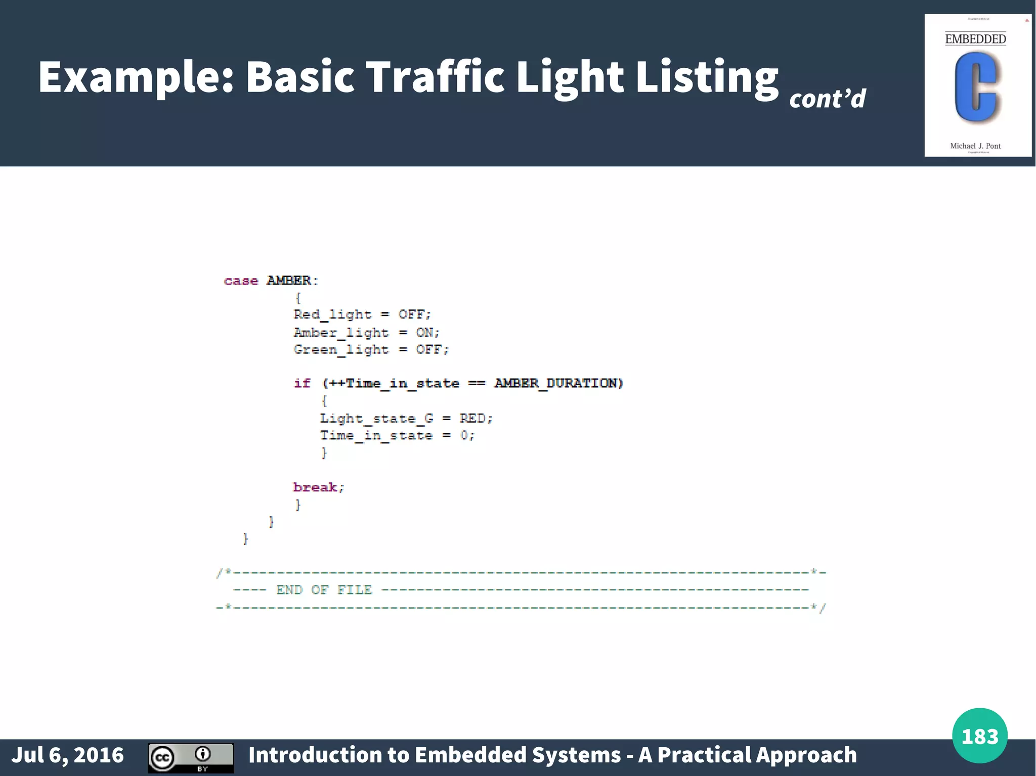
Concepts of multi-state systems with examples like traffic lights and washing machines.
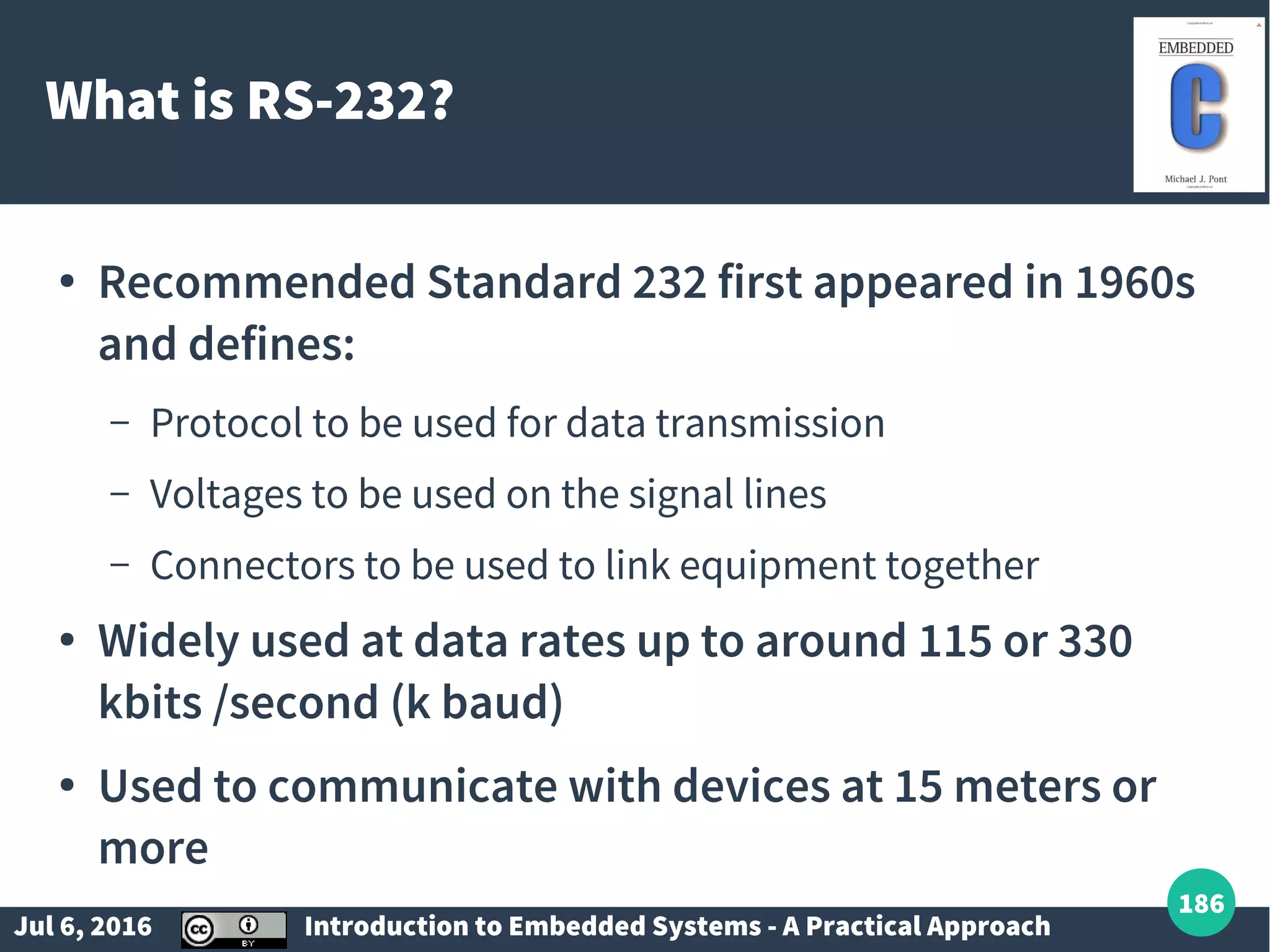
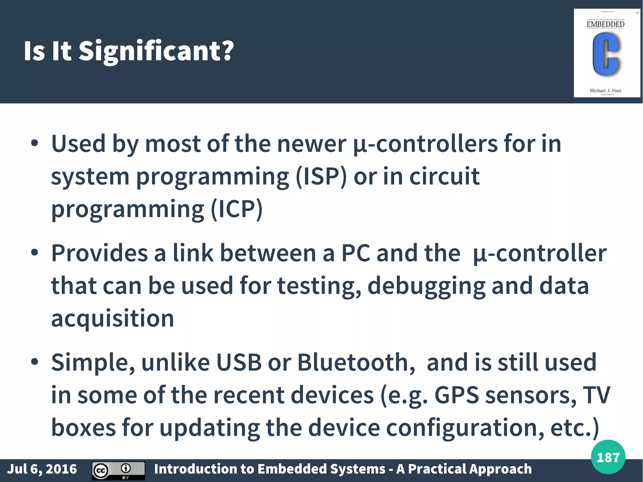
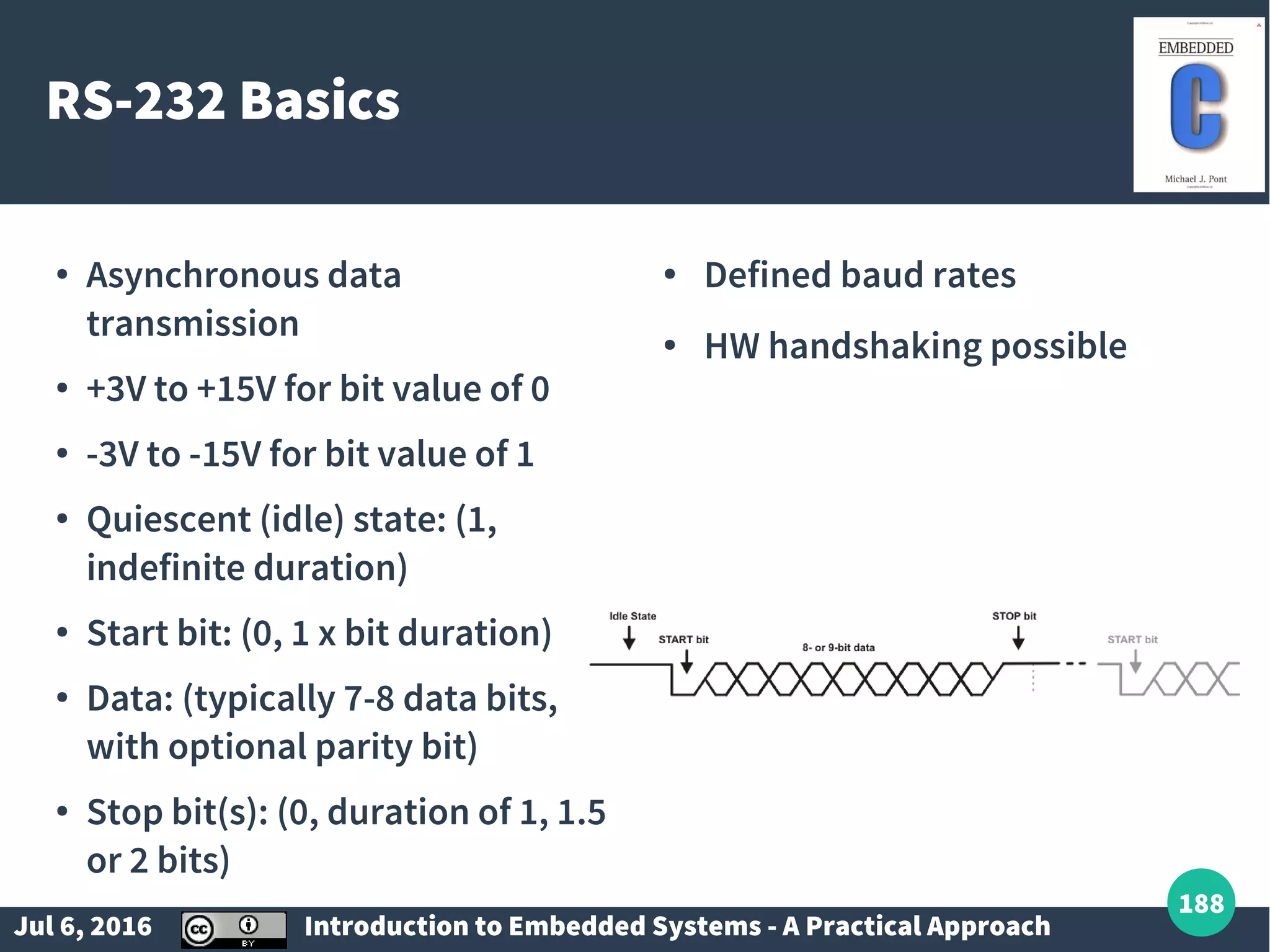
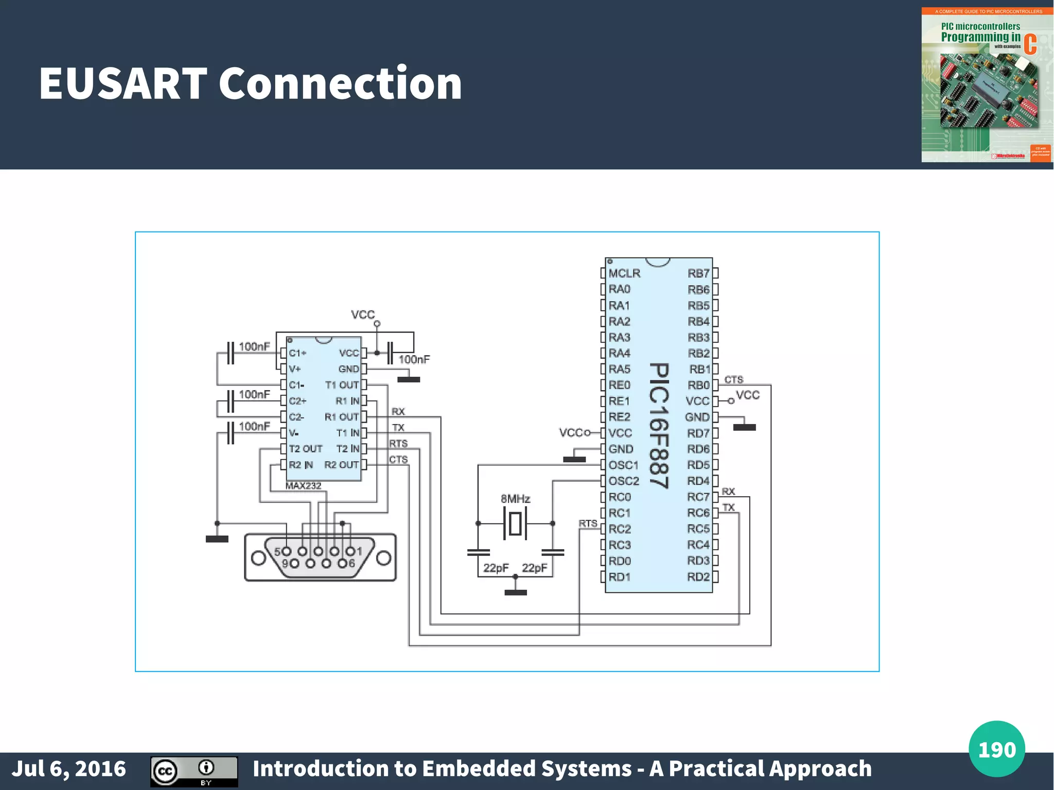
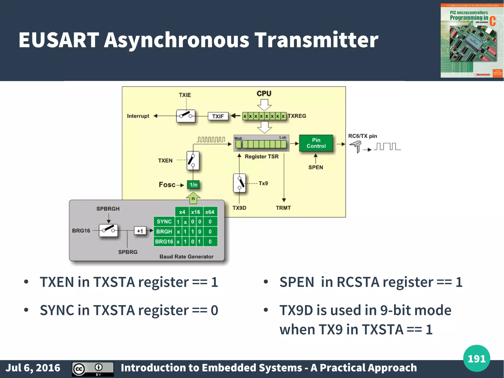
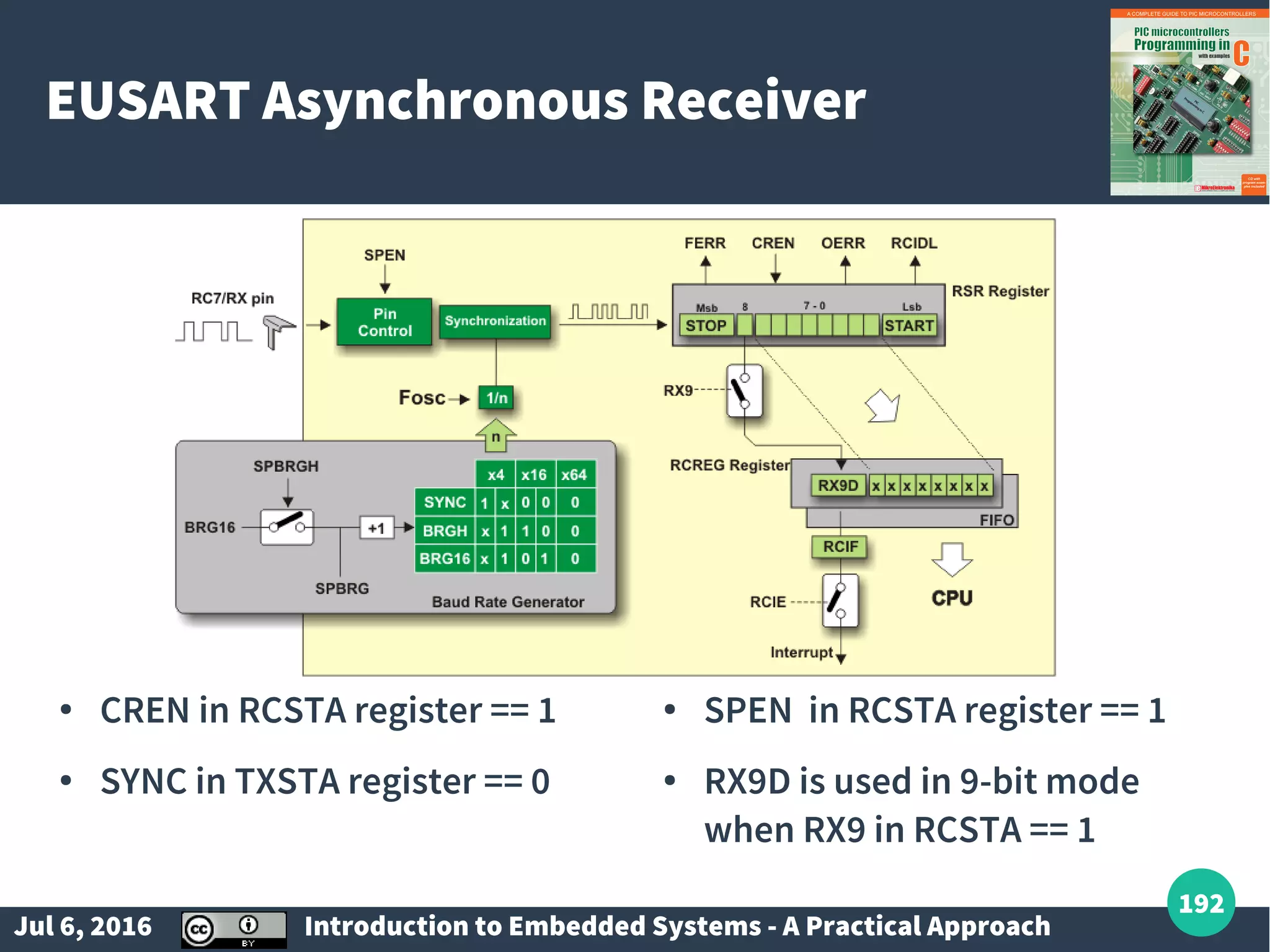
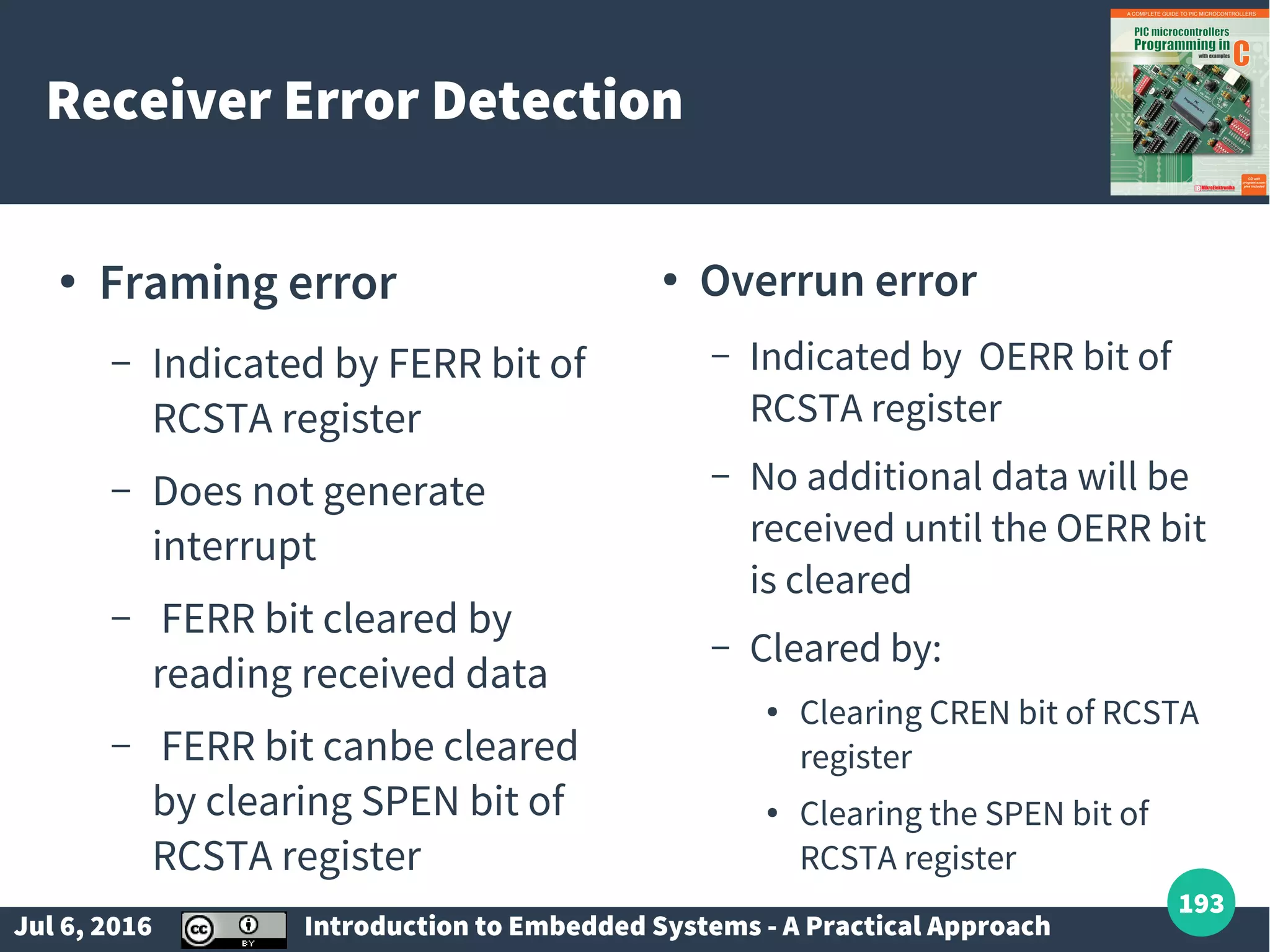
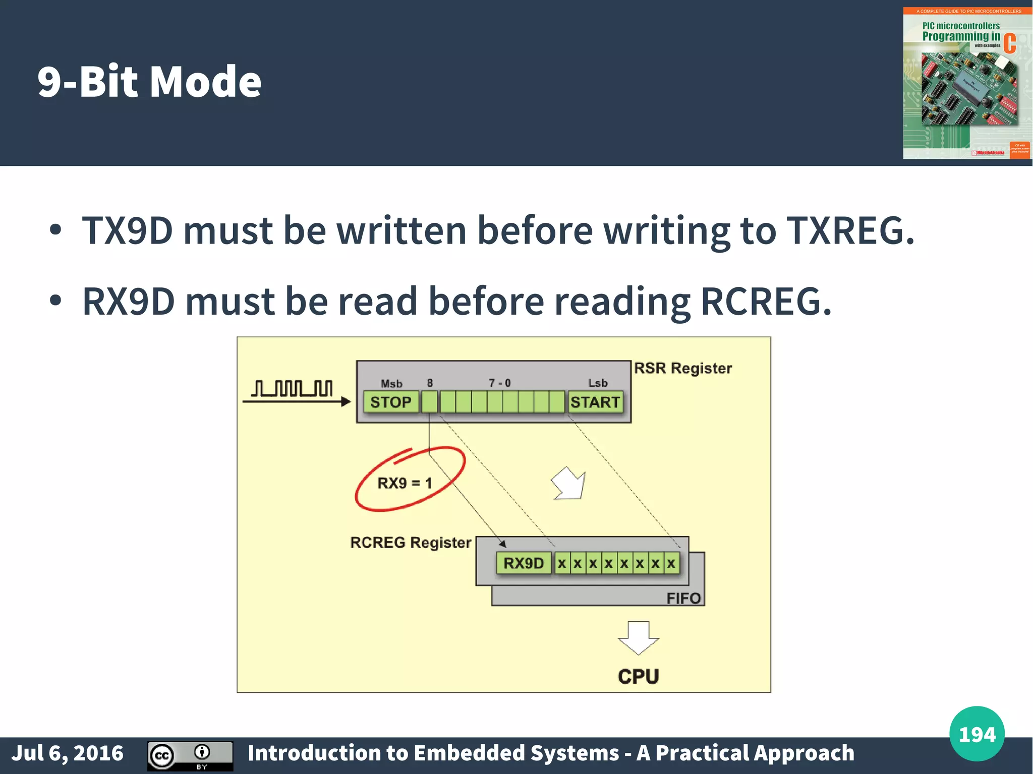
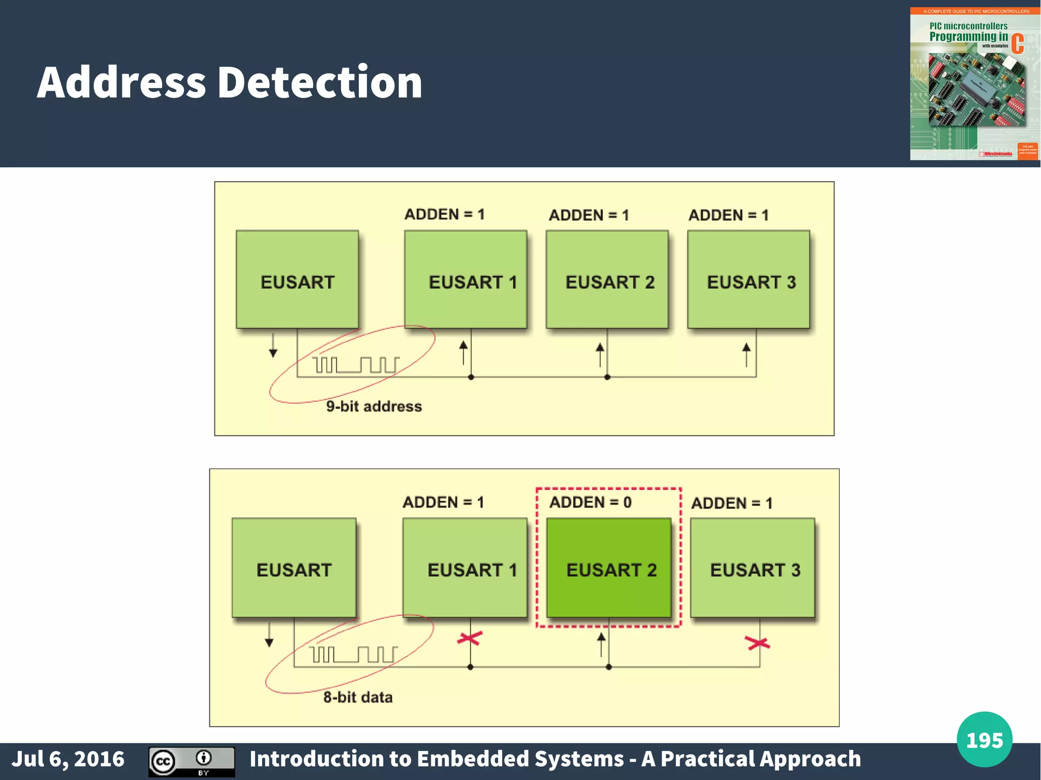
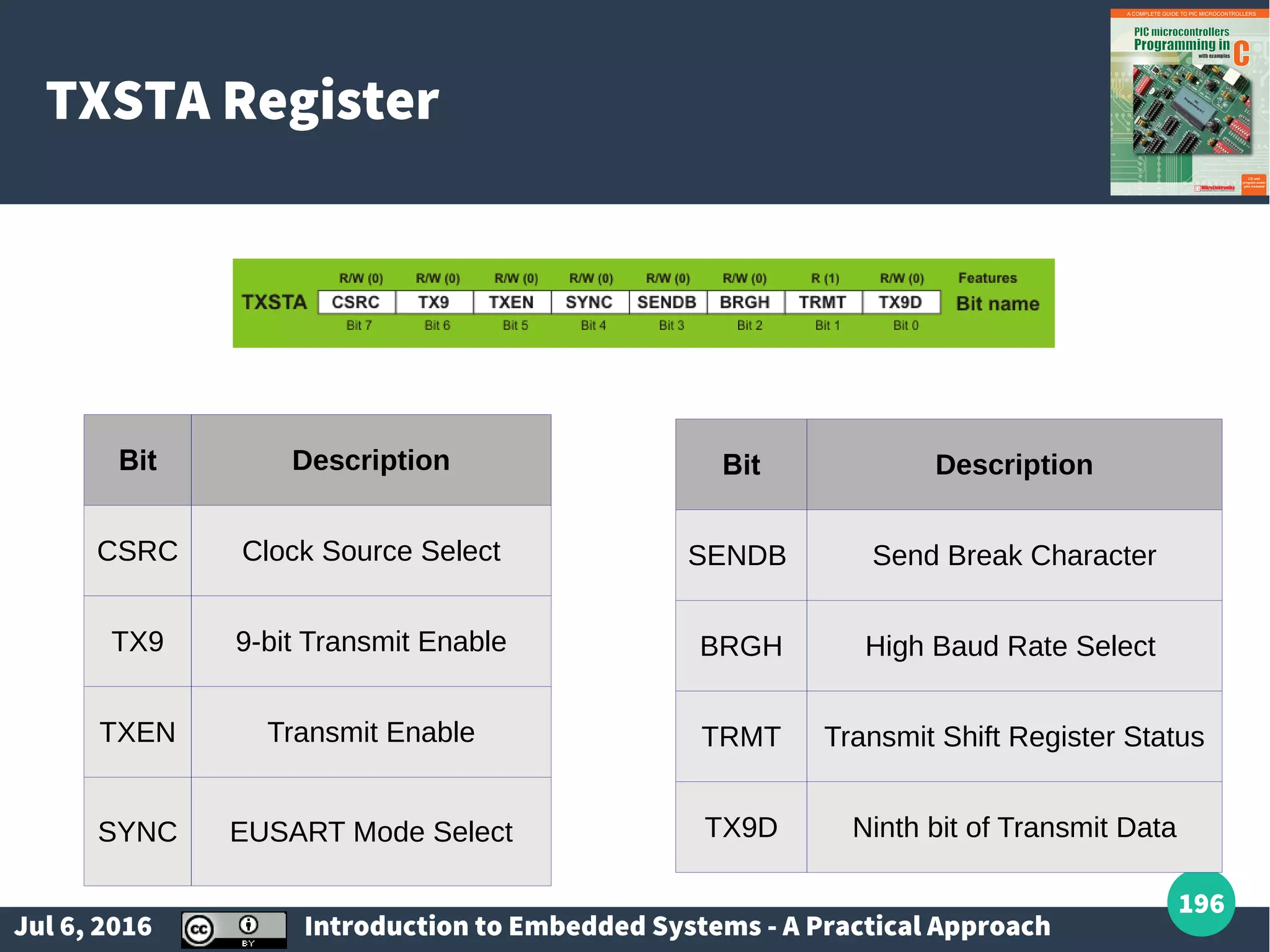
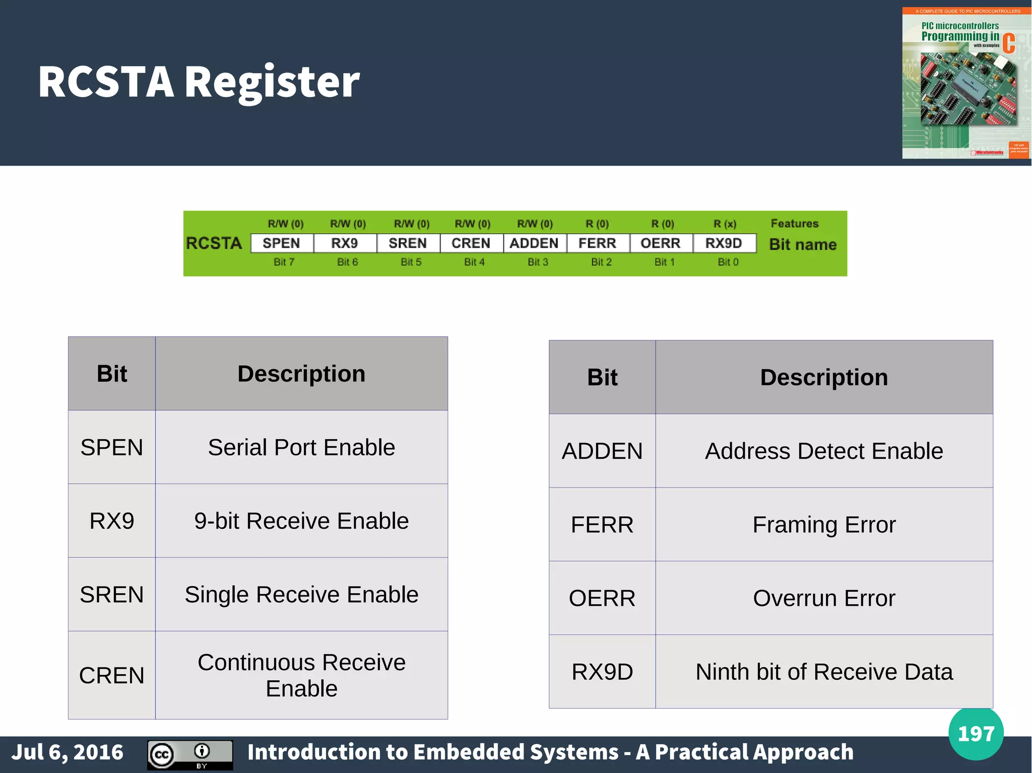
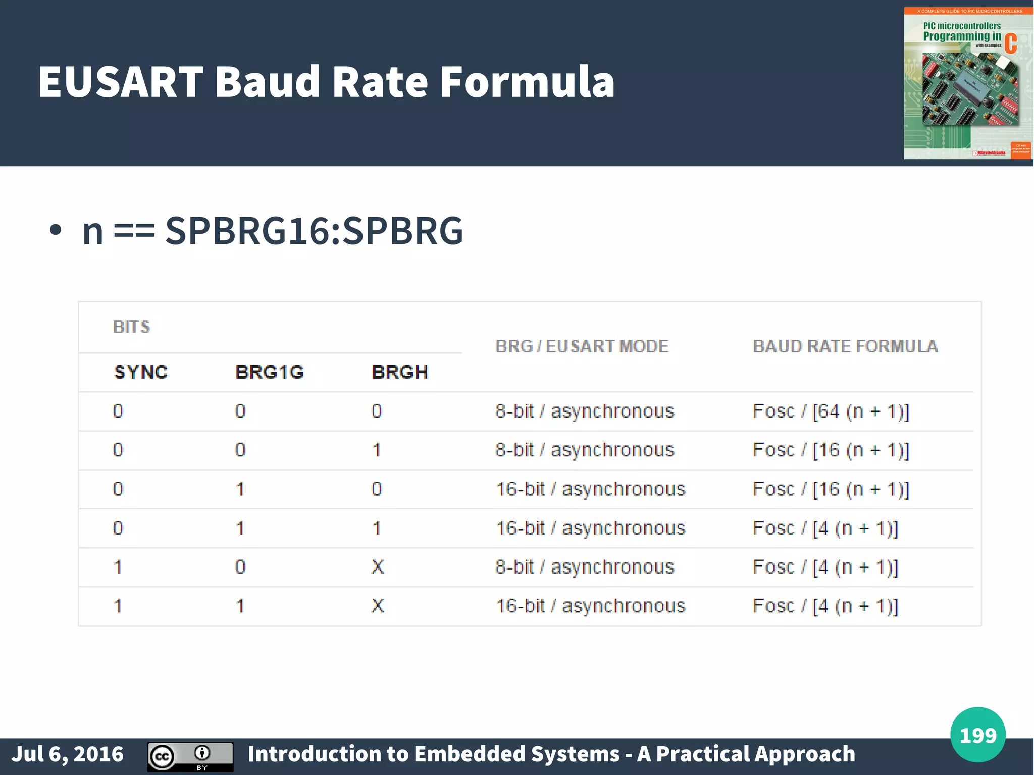
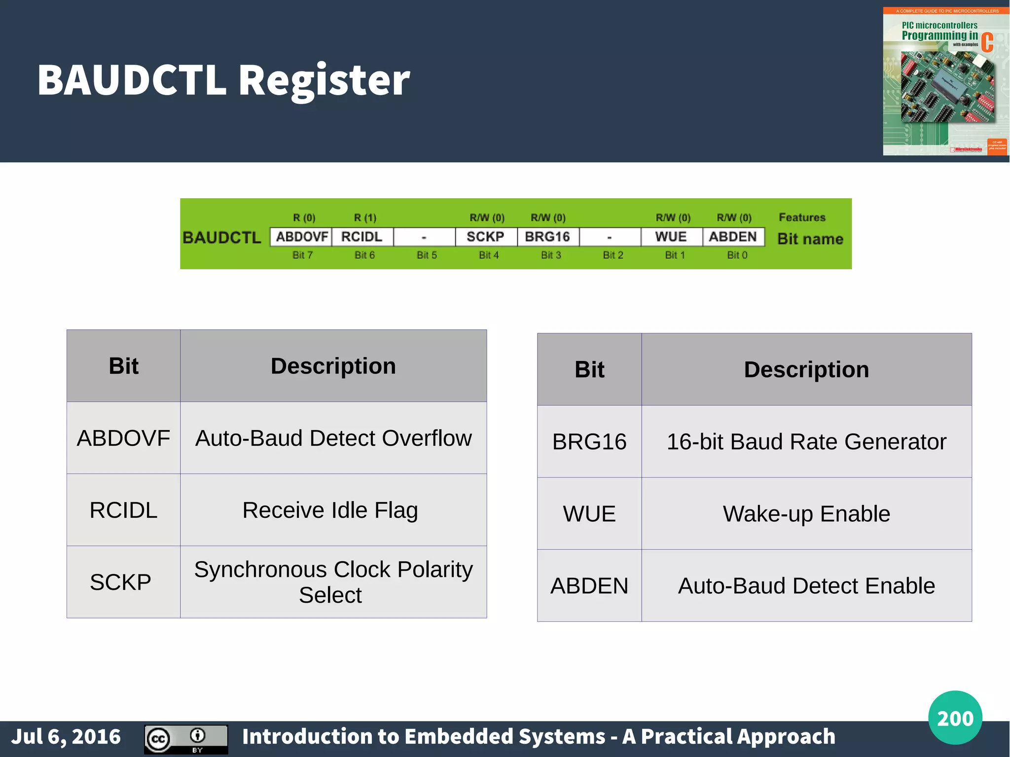
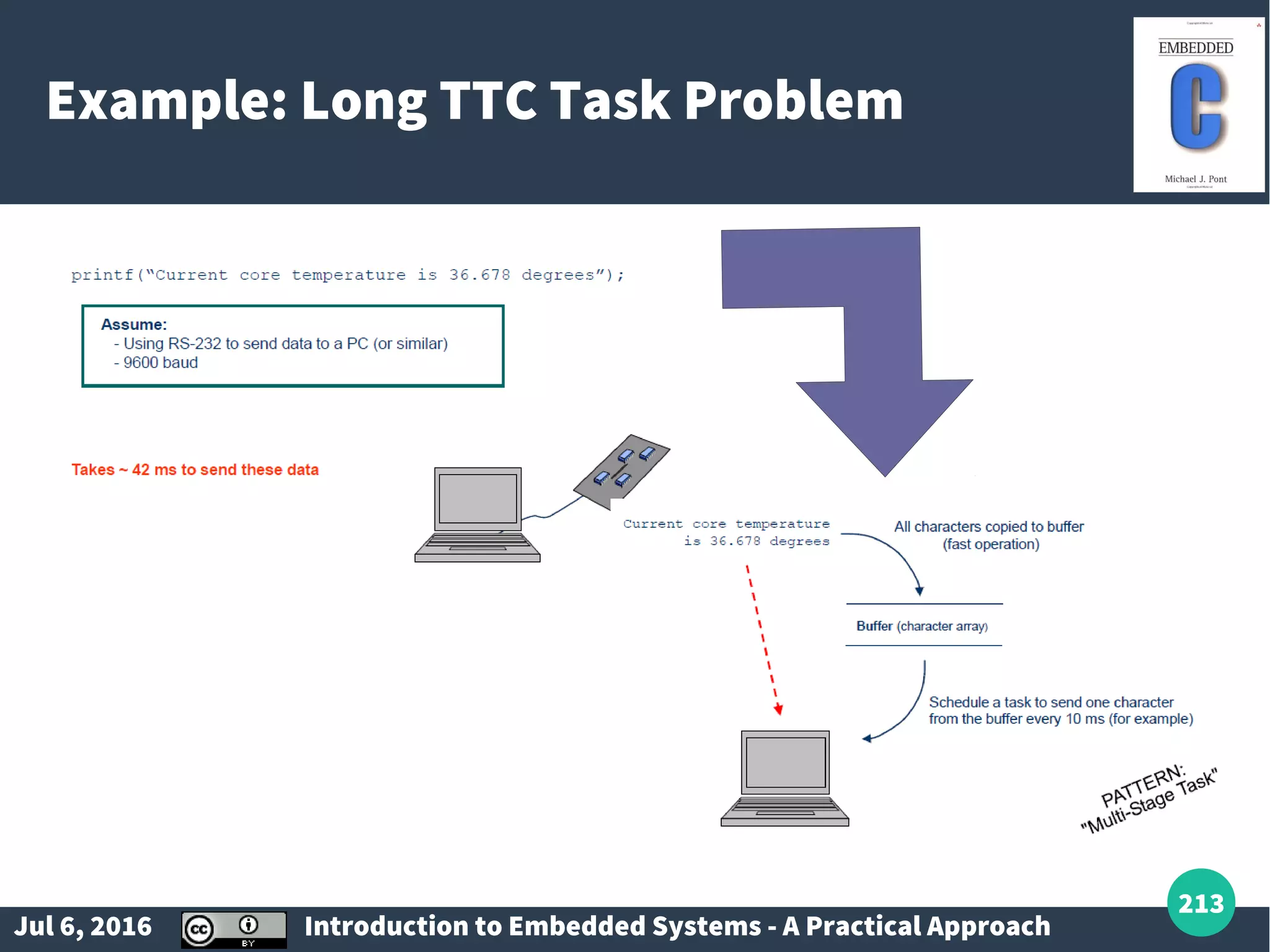
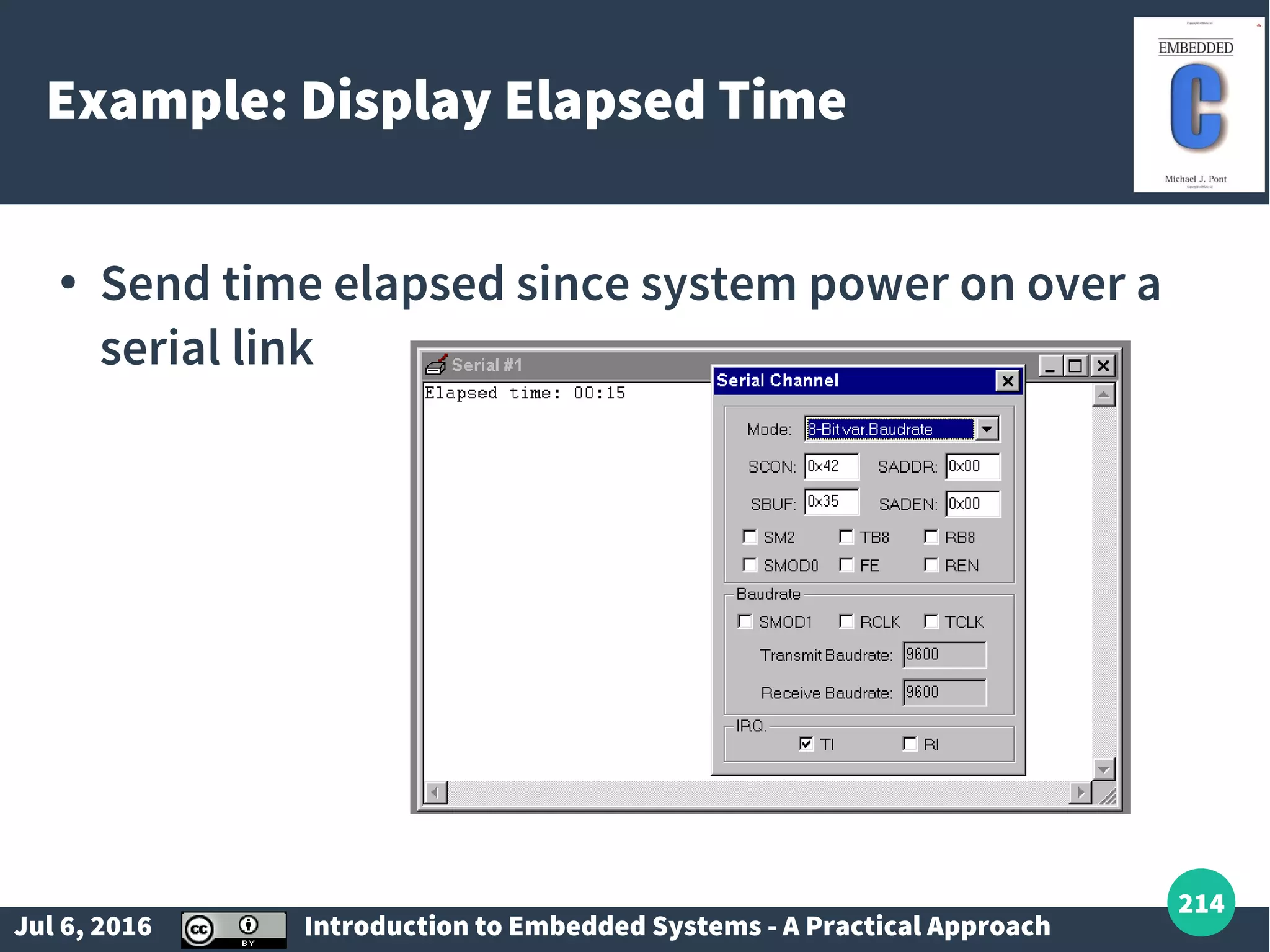
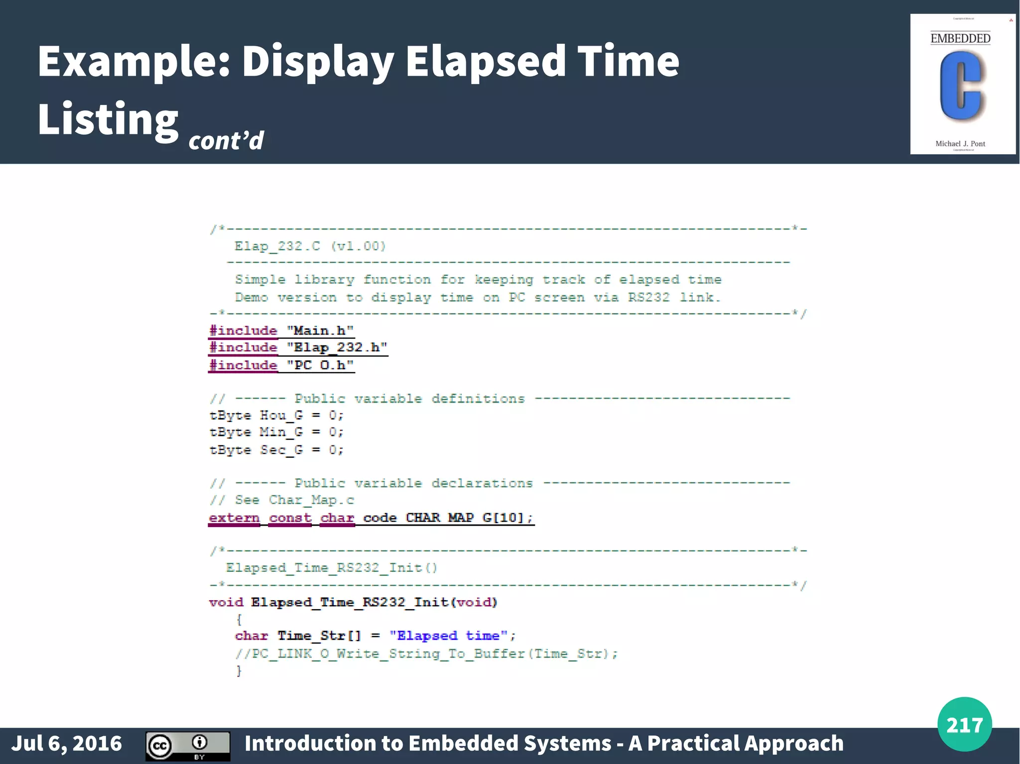
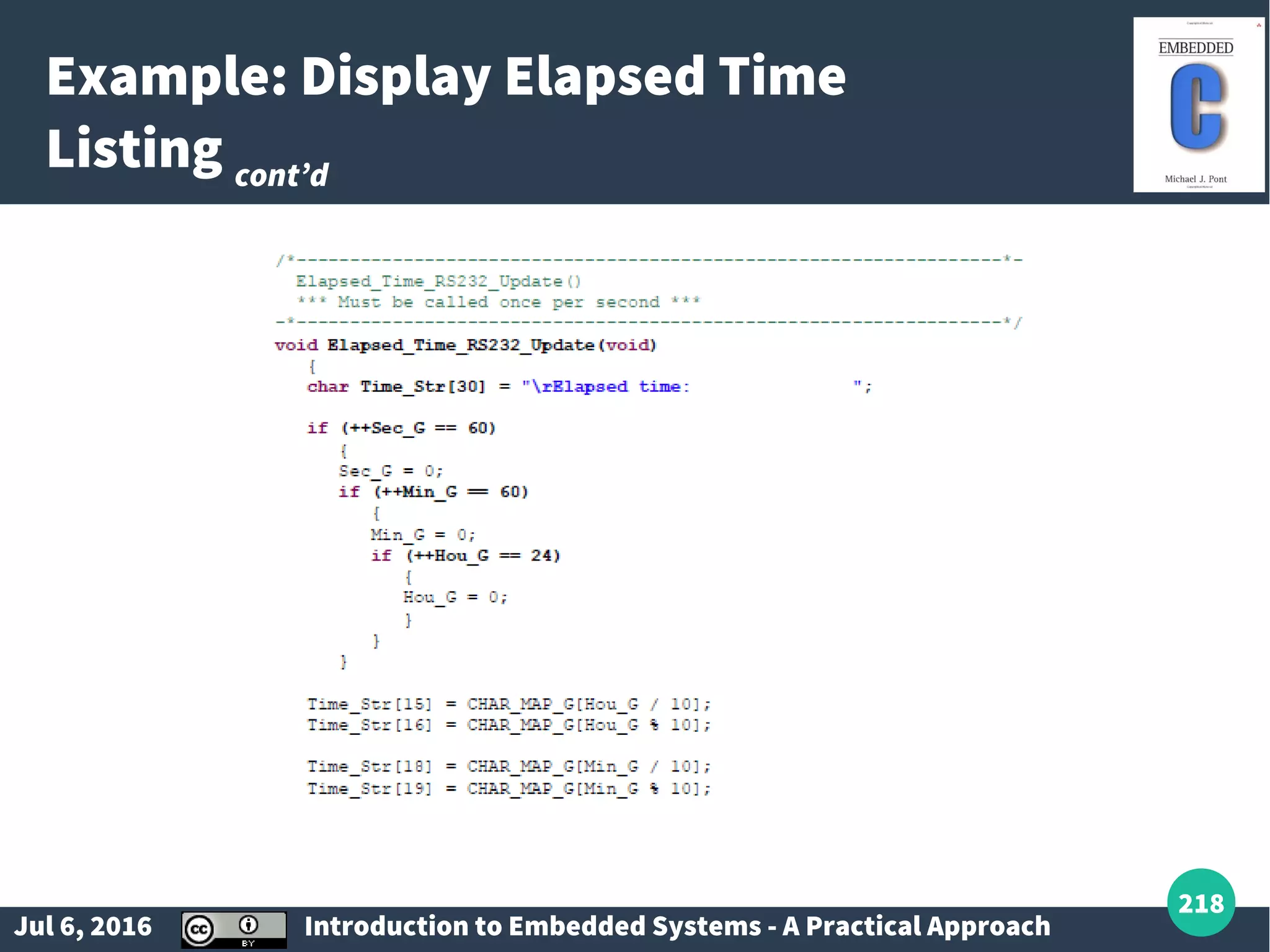
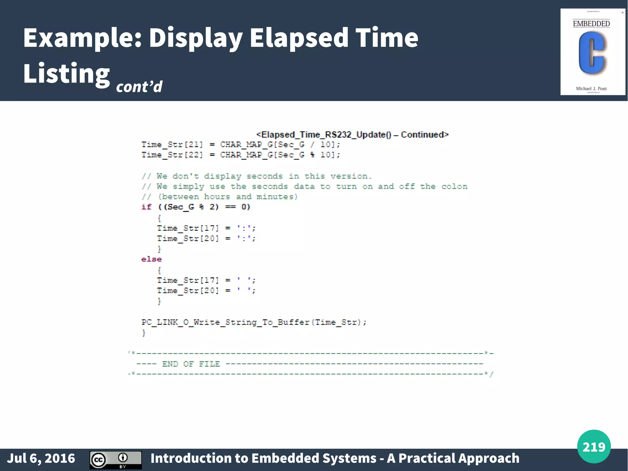
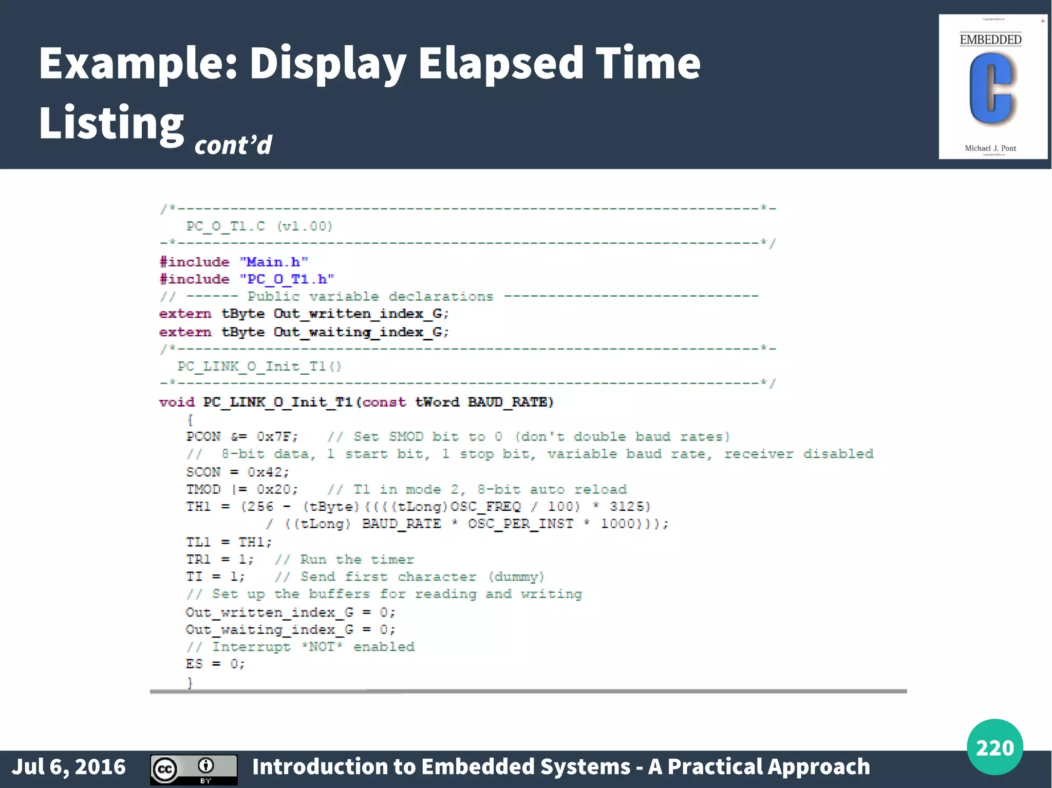
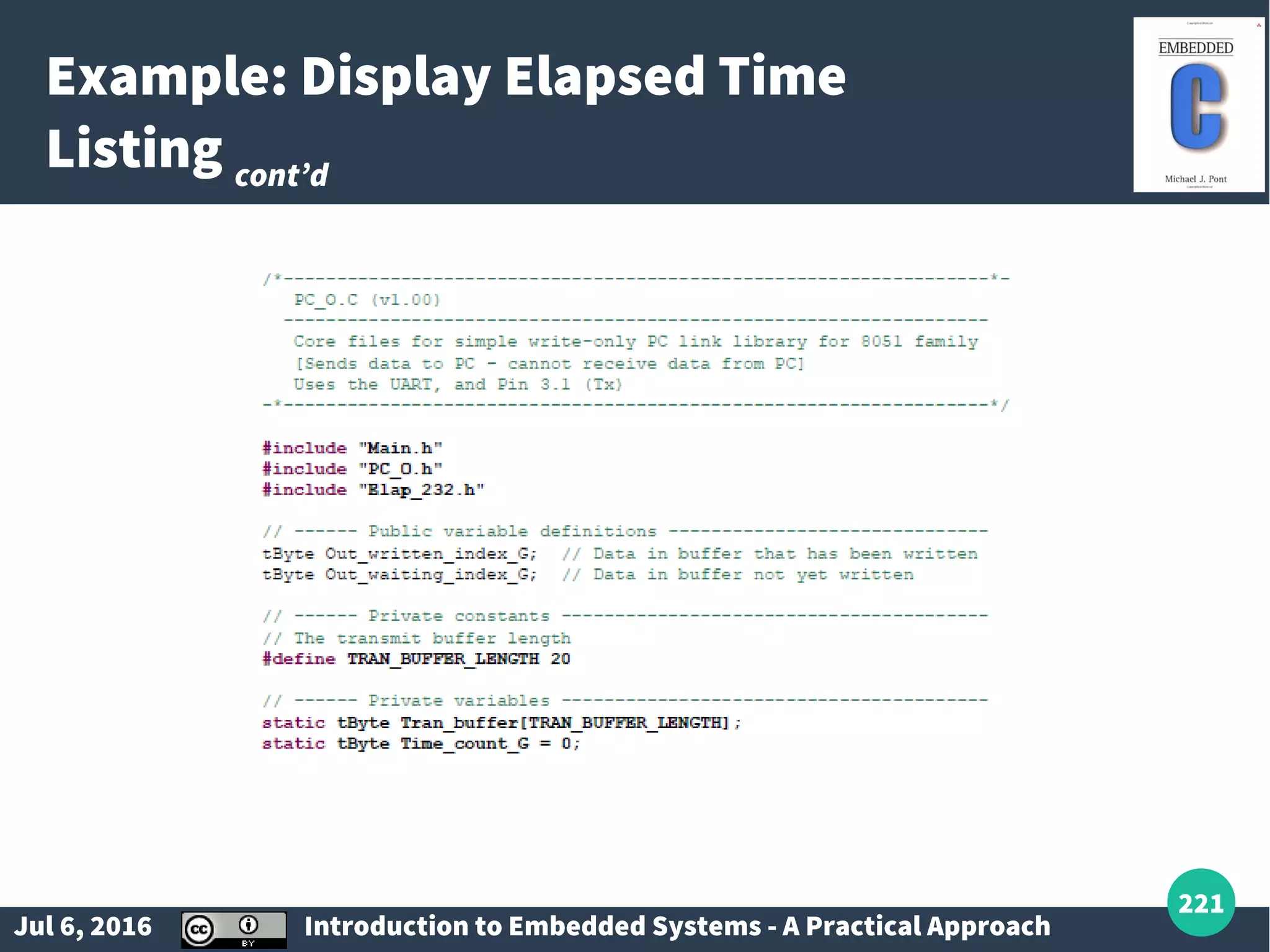
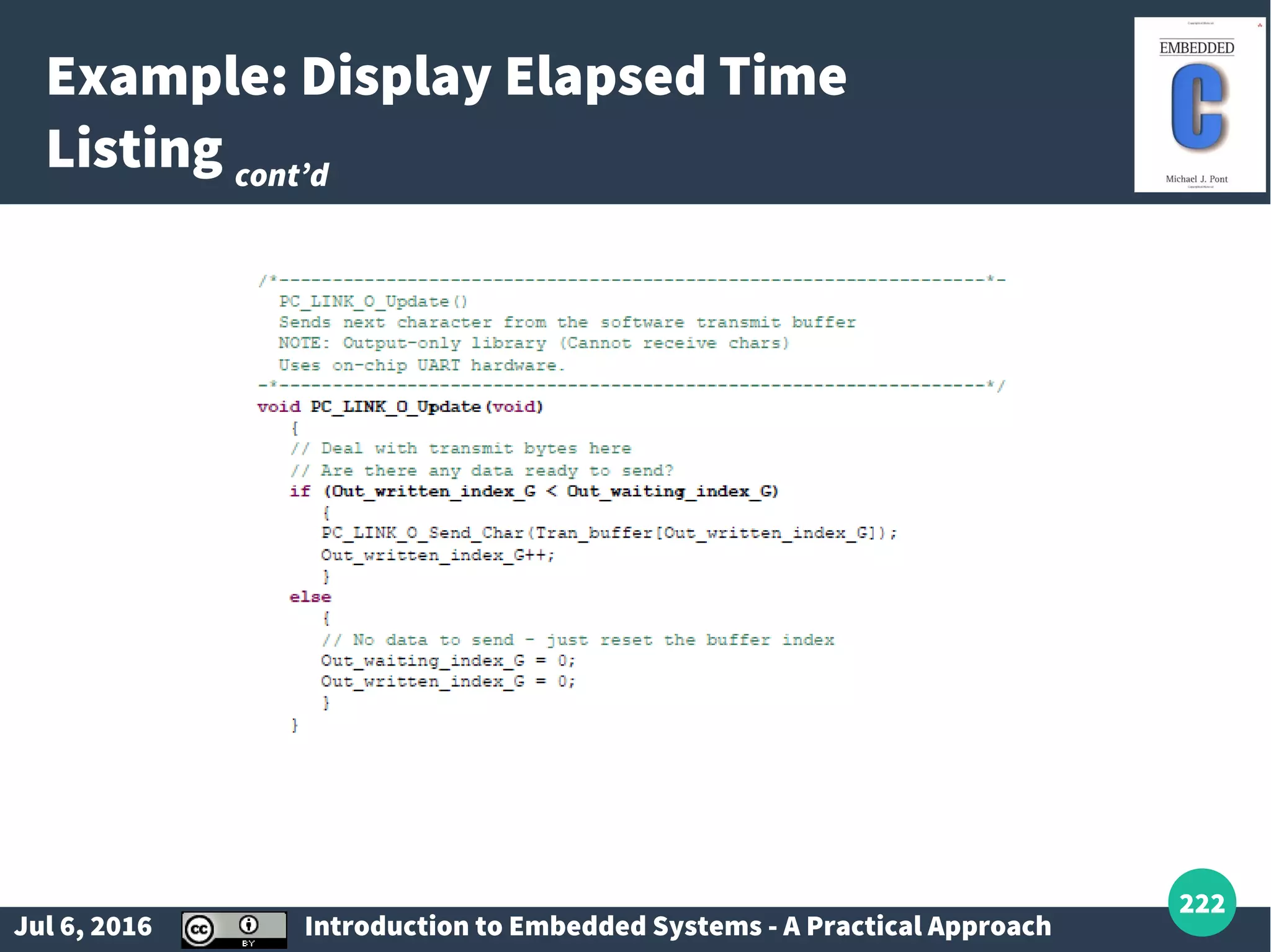
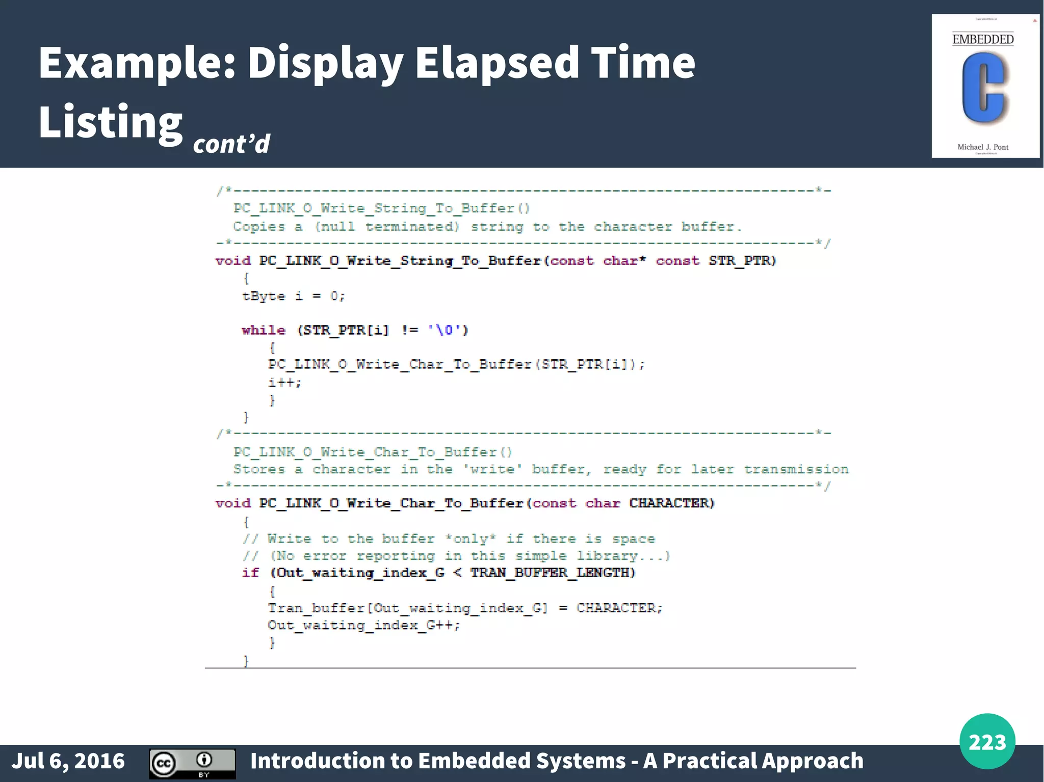
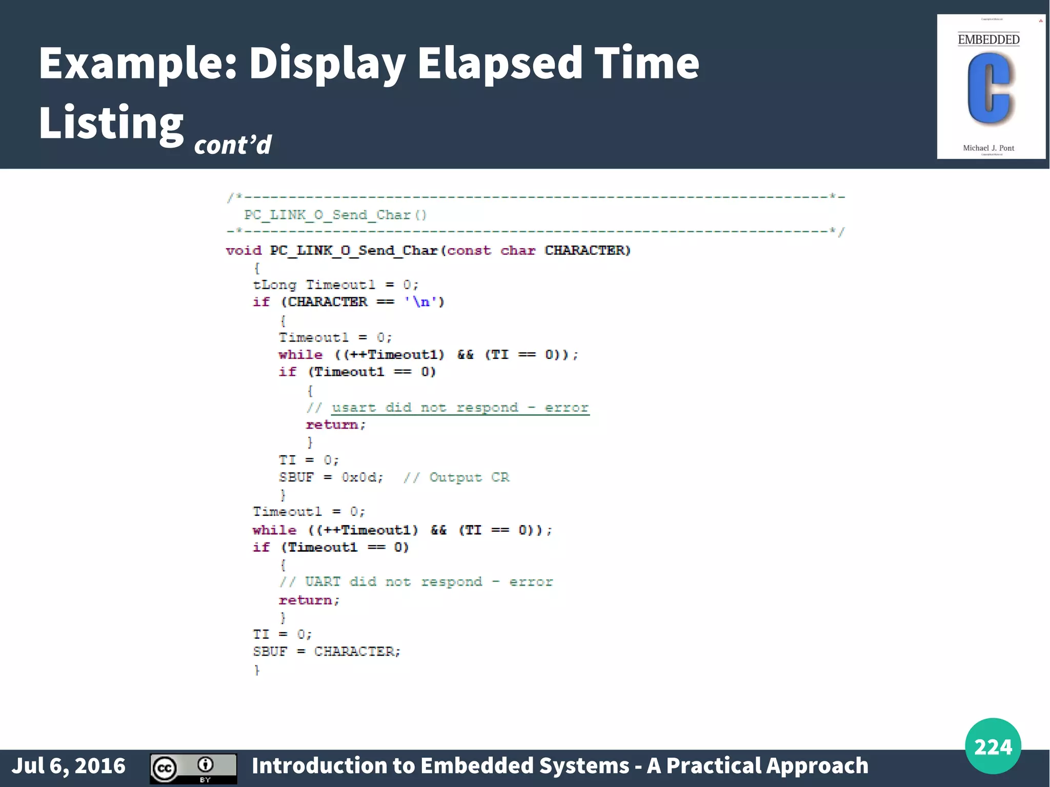
Introduction to RS-232, EUSART functionalities, and implementation details in embedded systems.
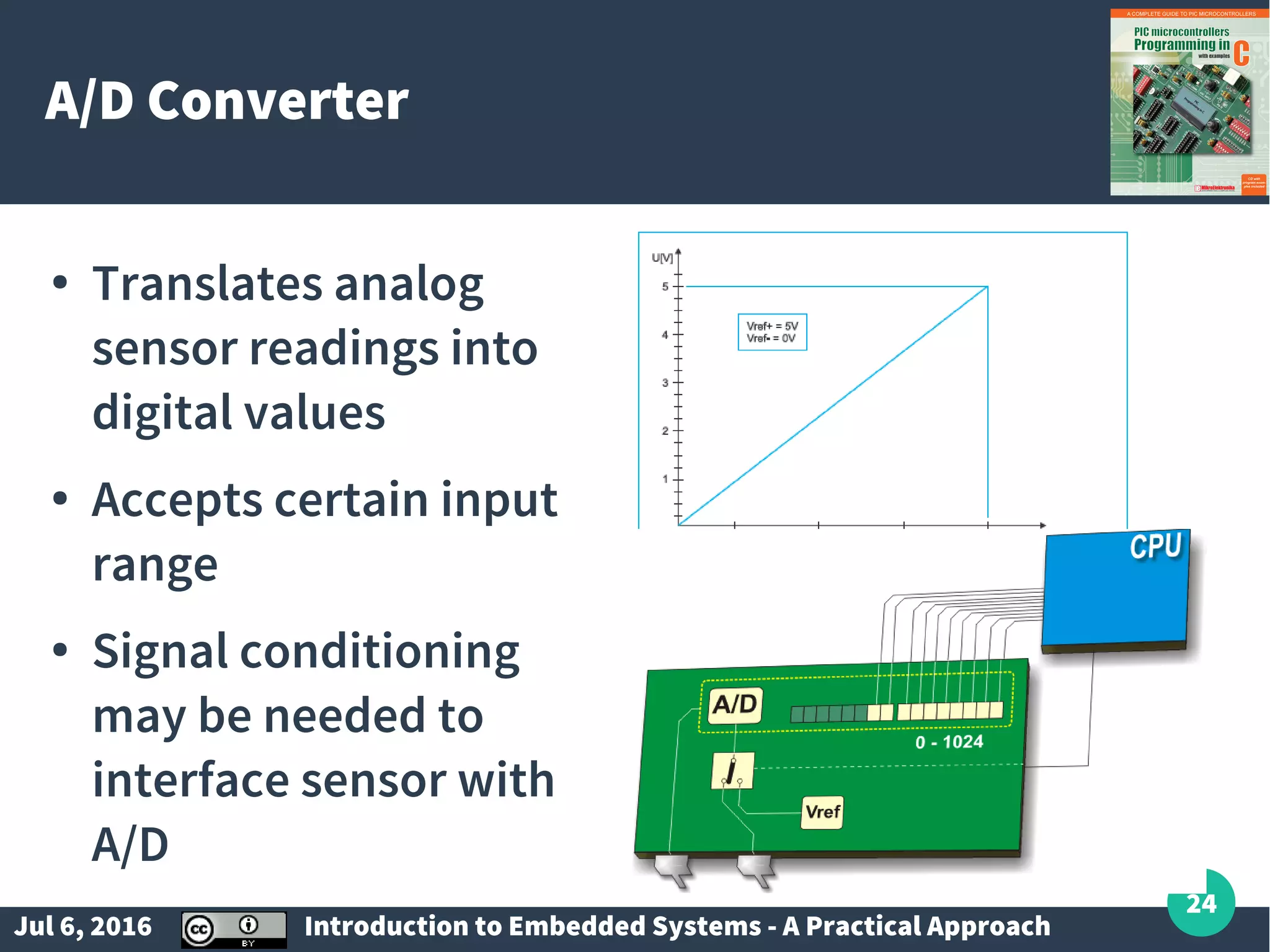
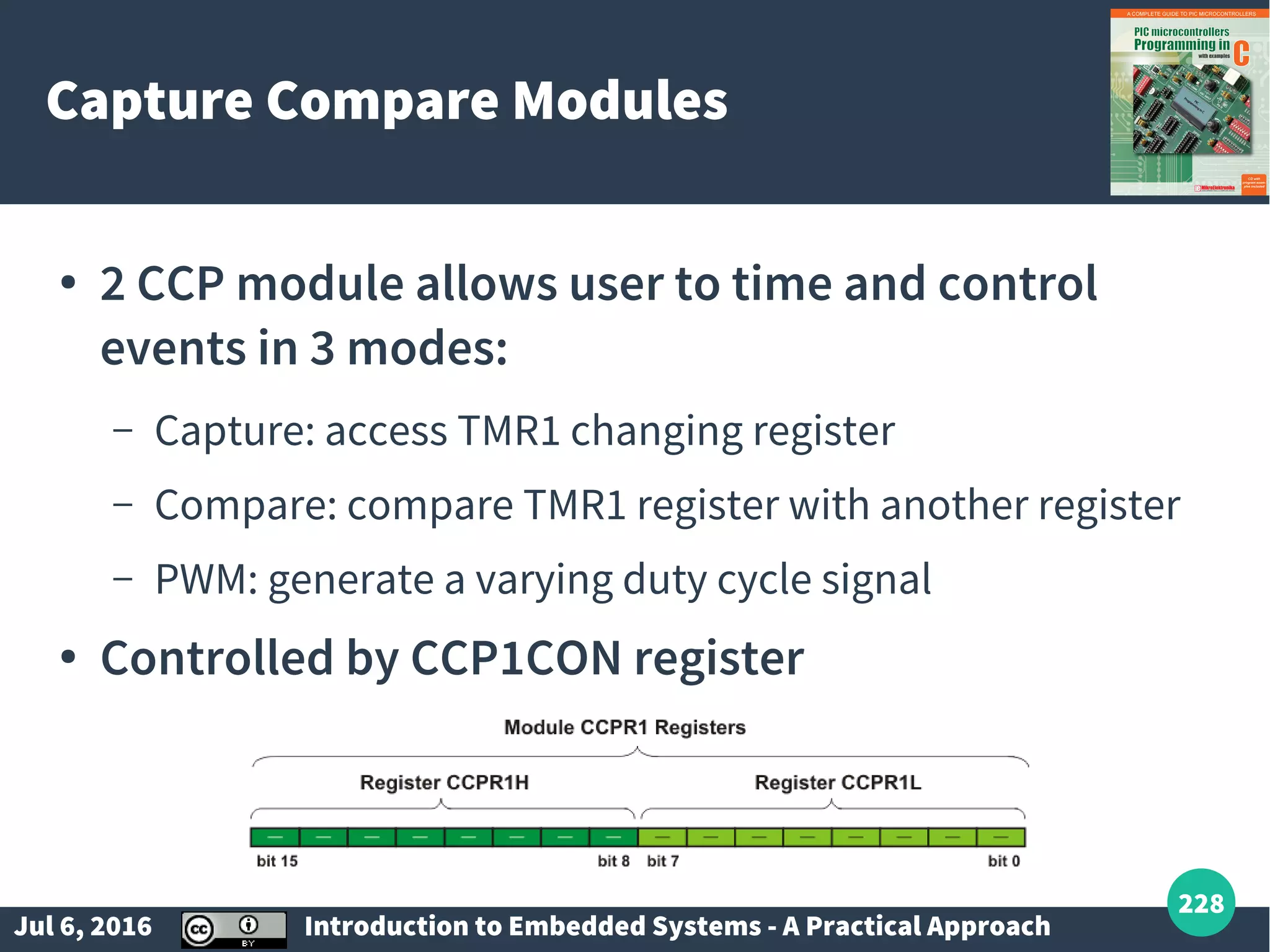
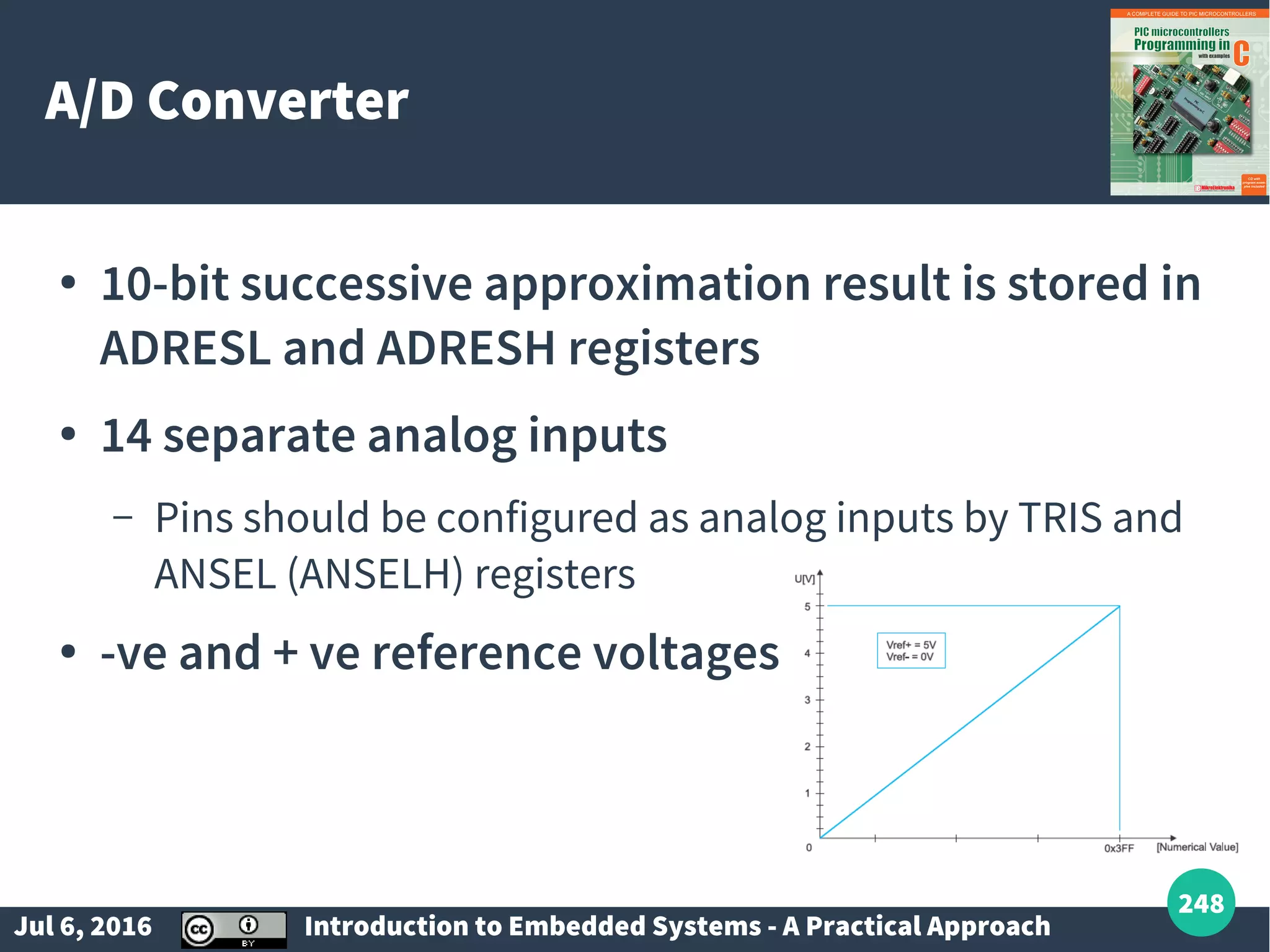
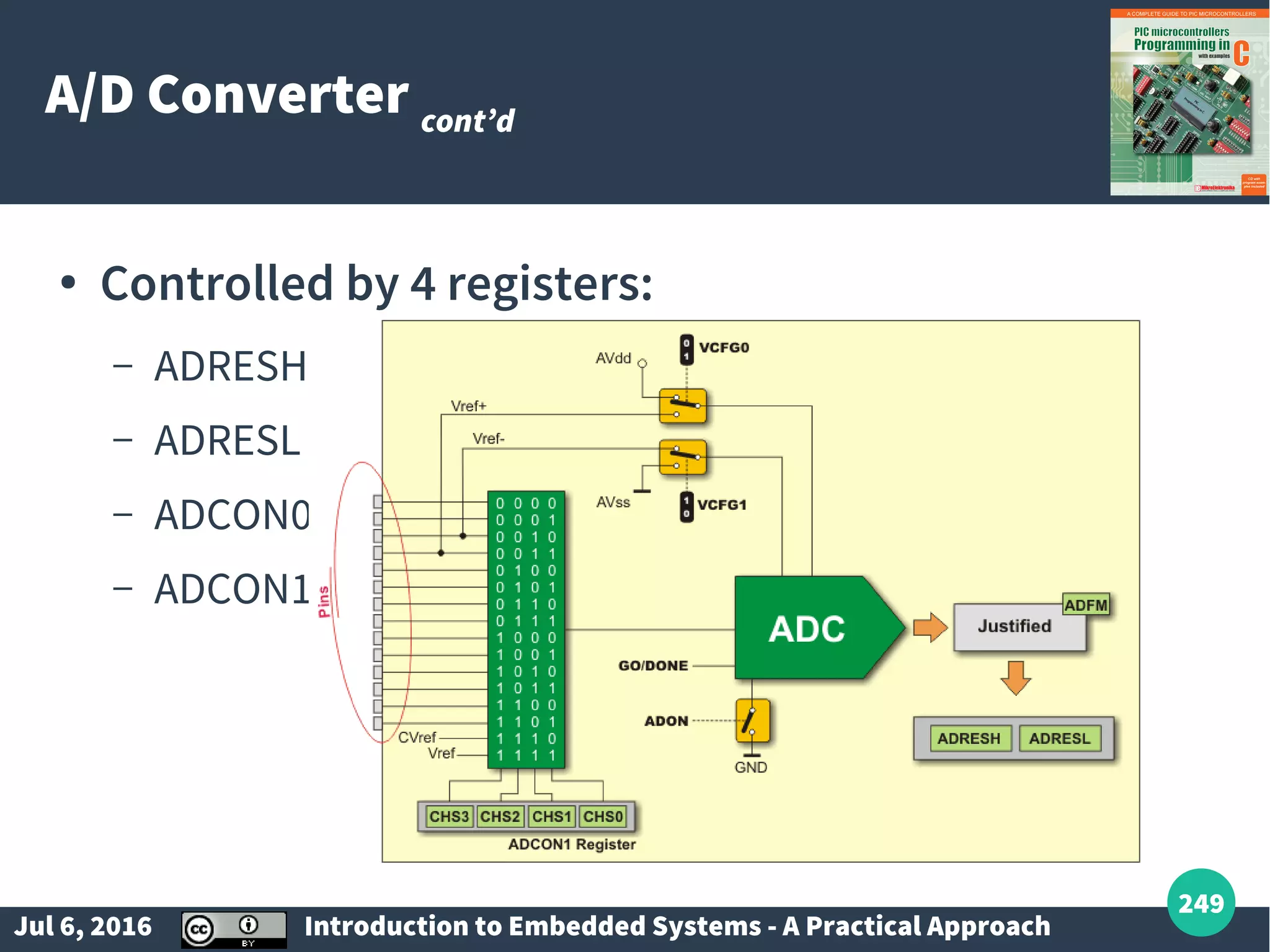
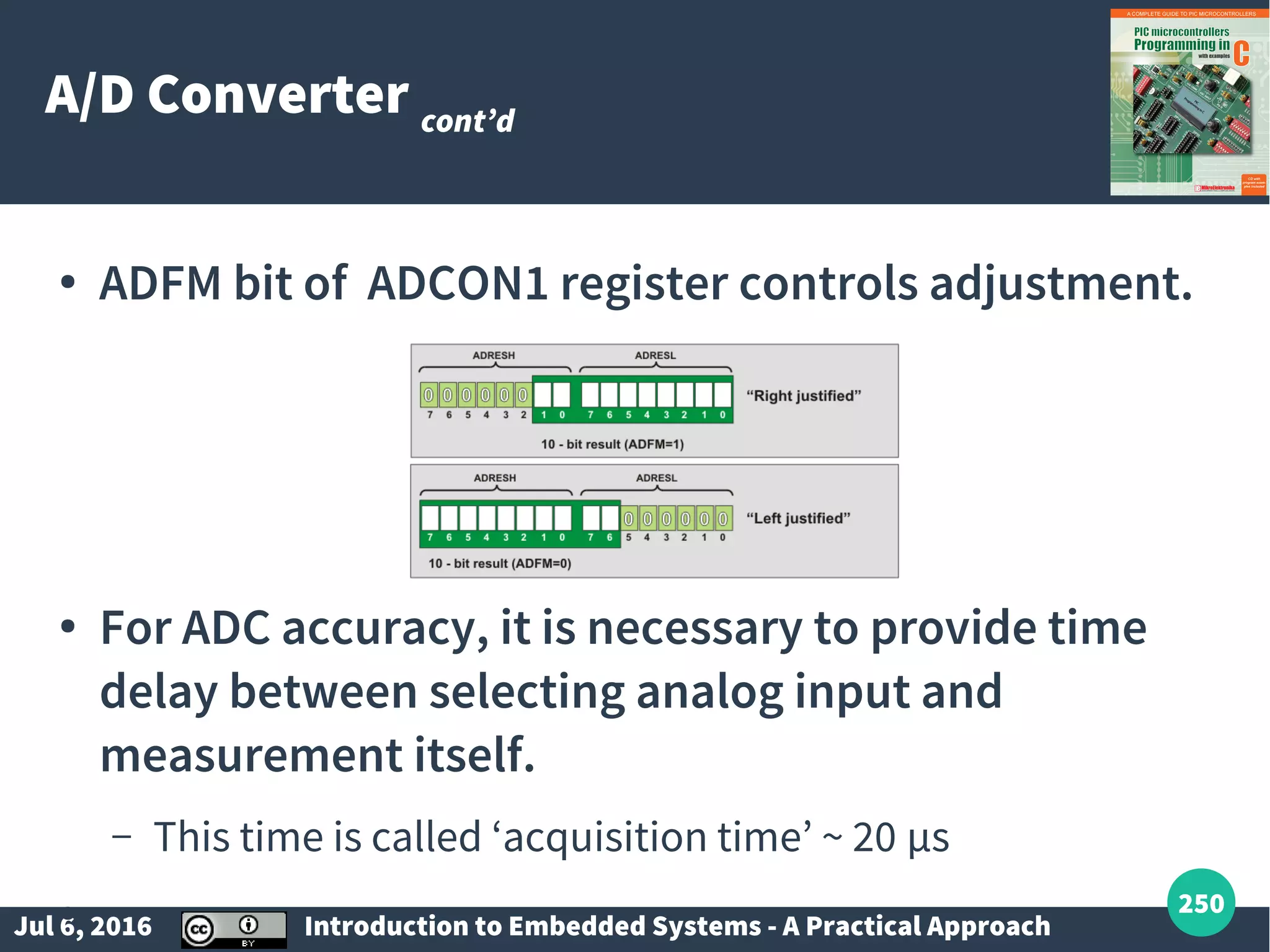
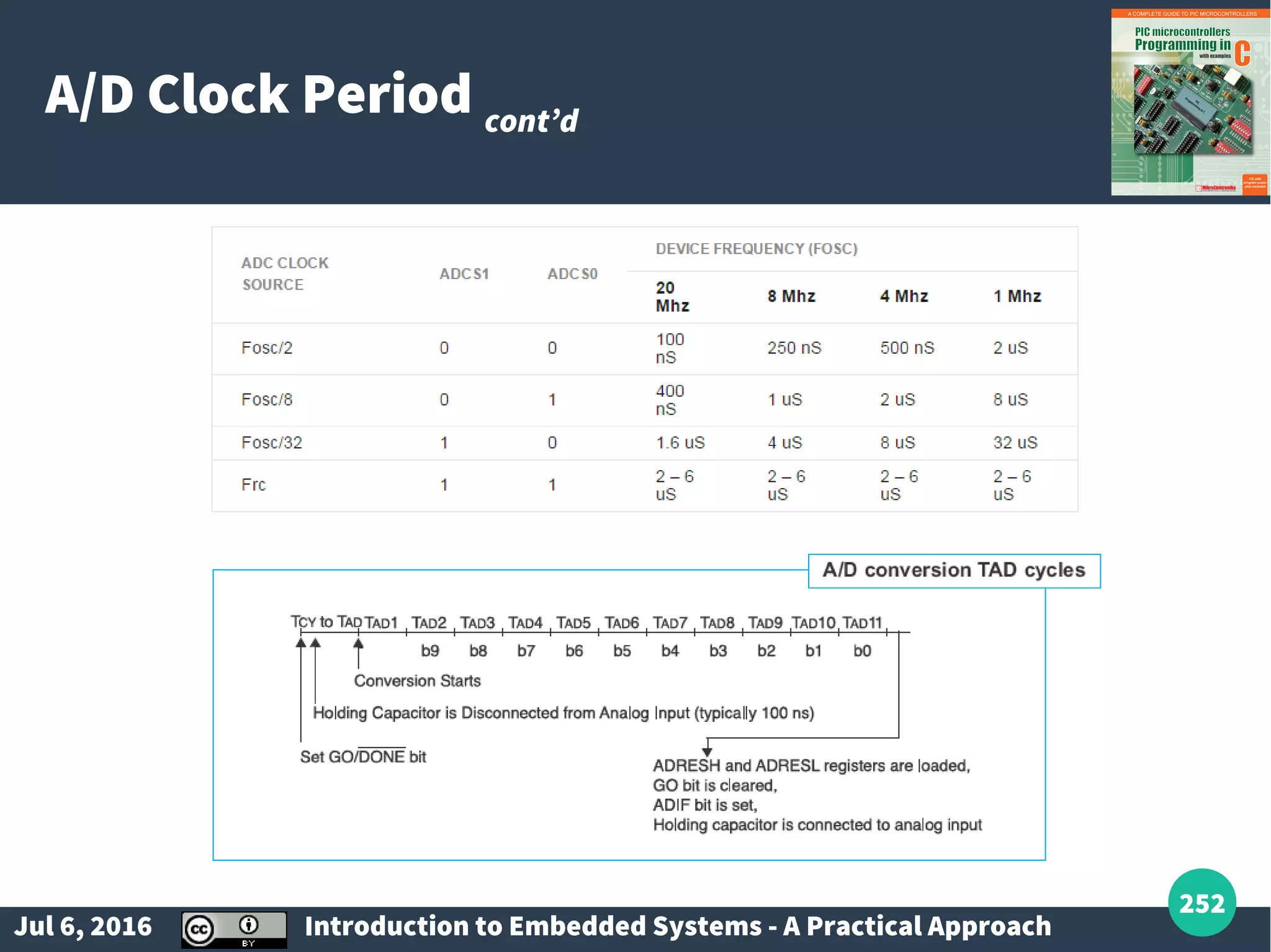
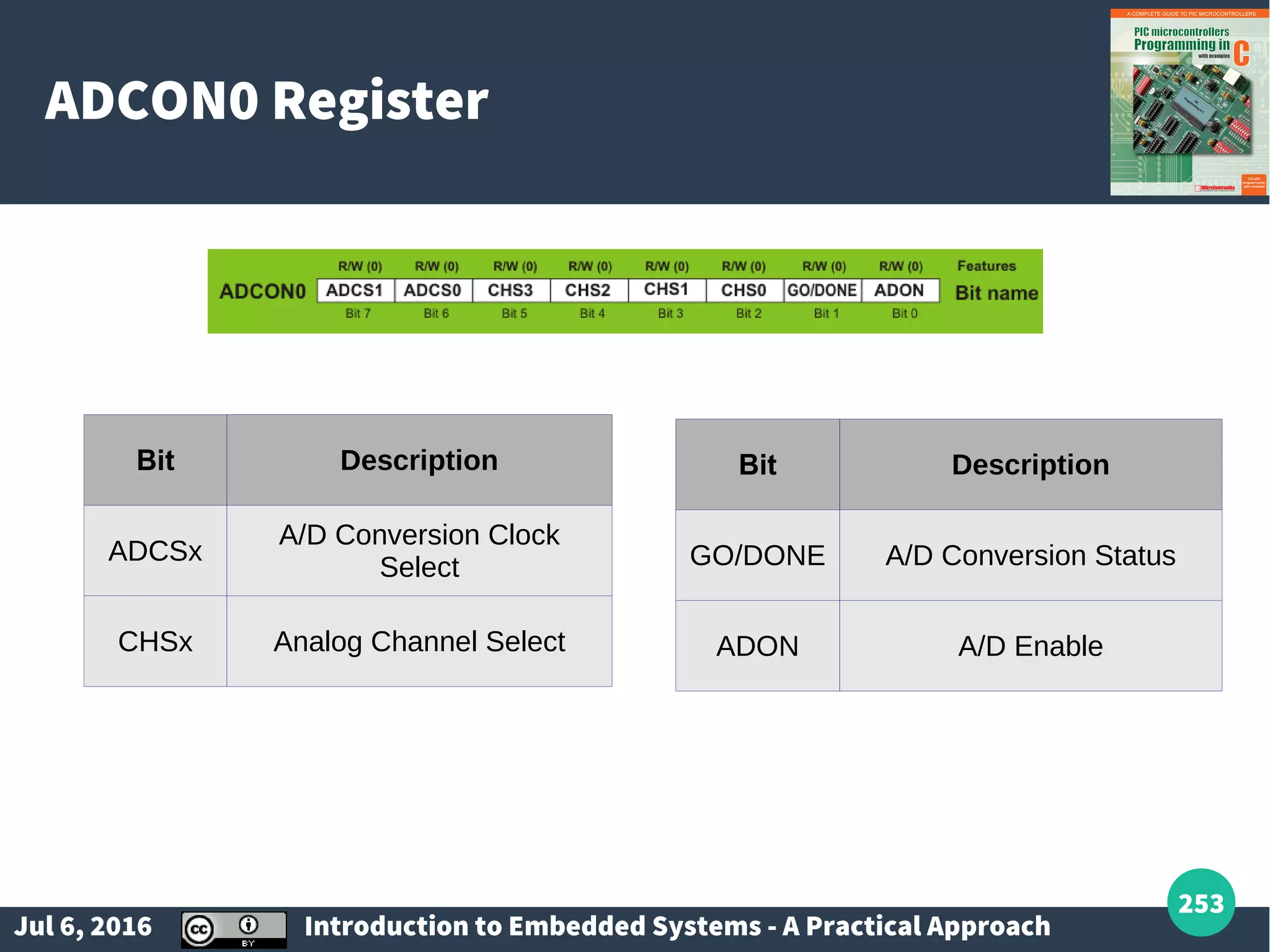
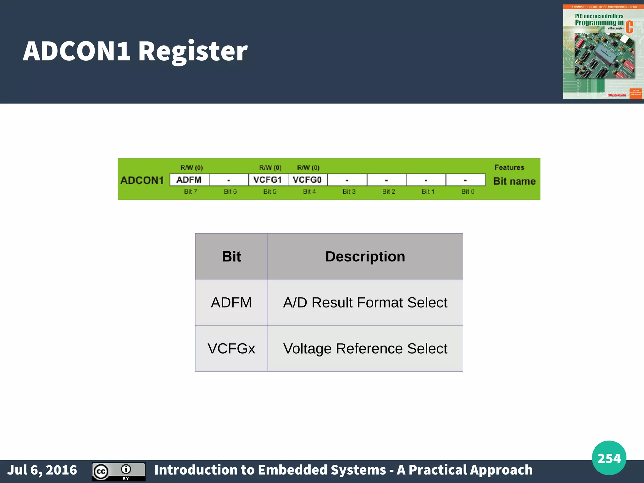
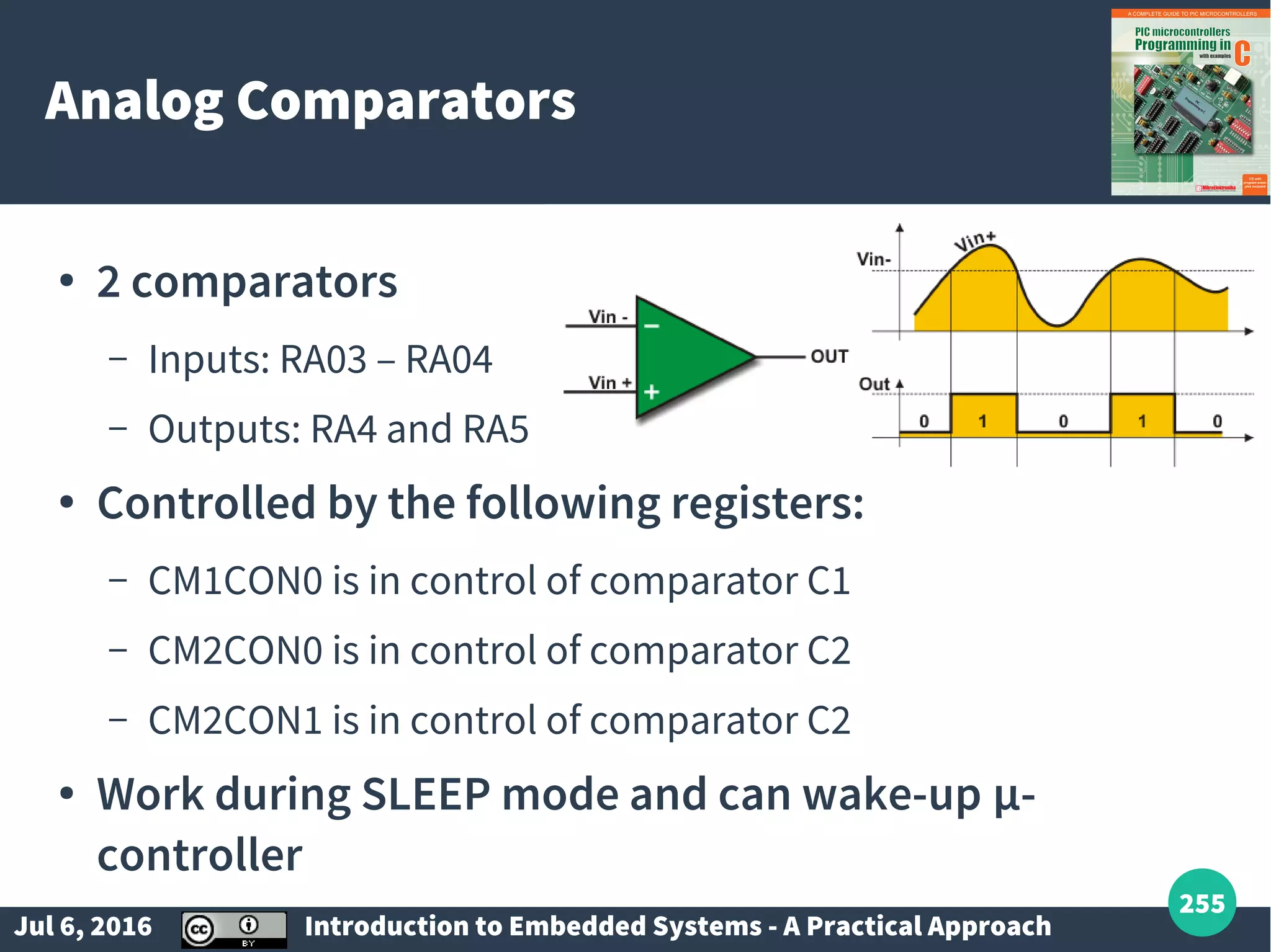
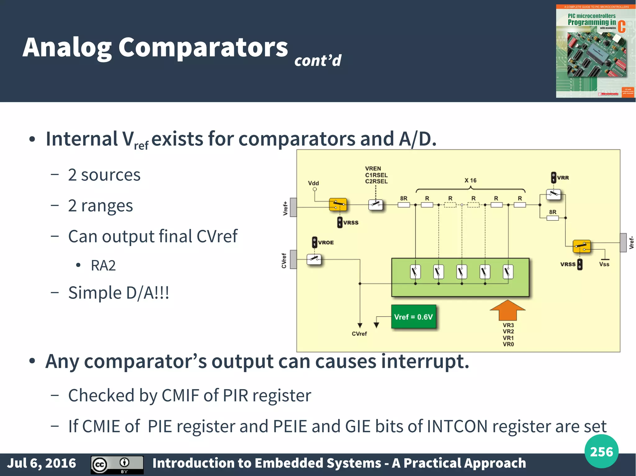
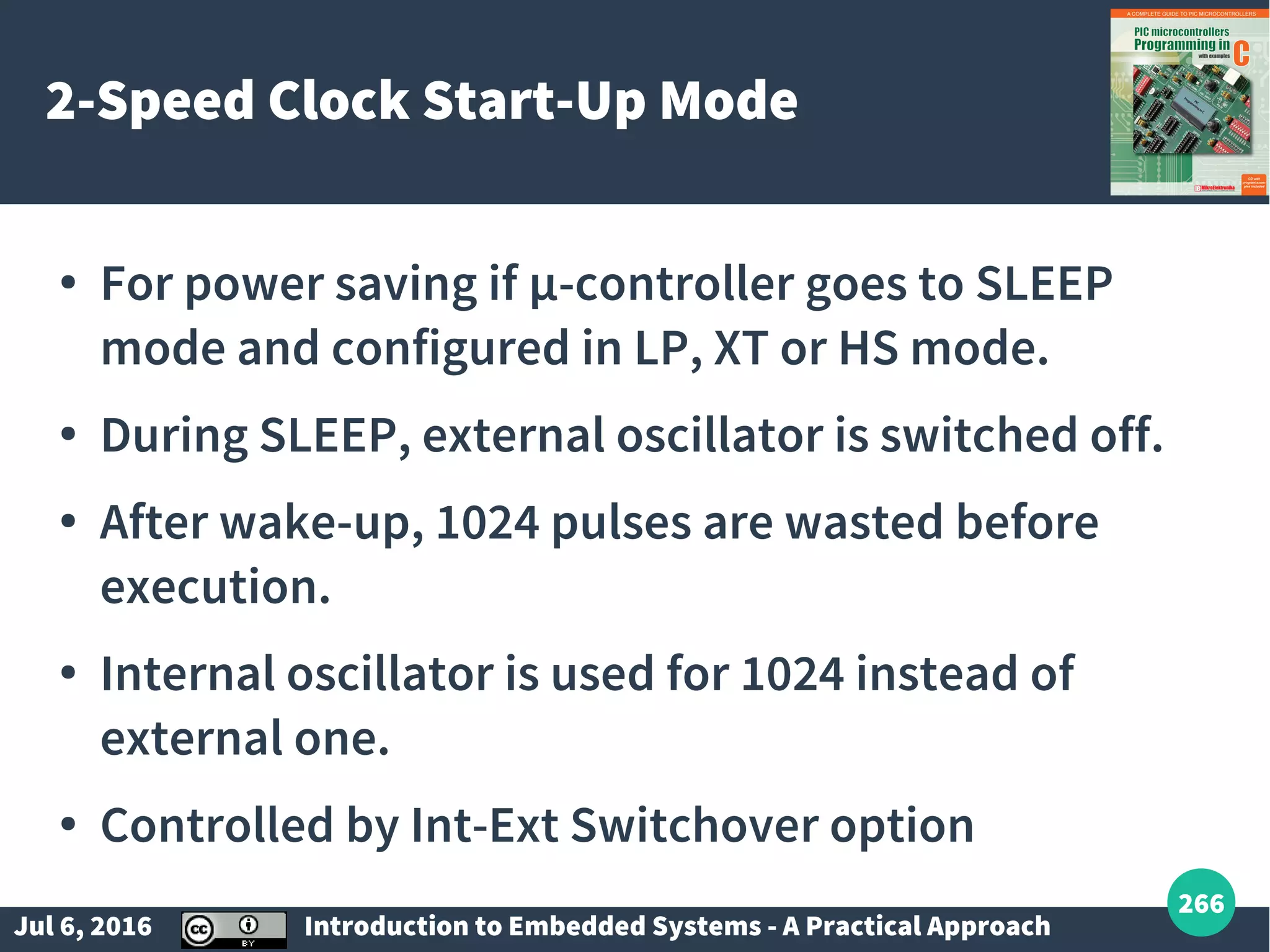
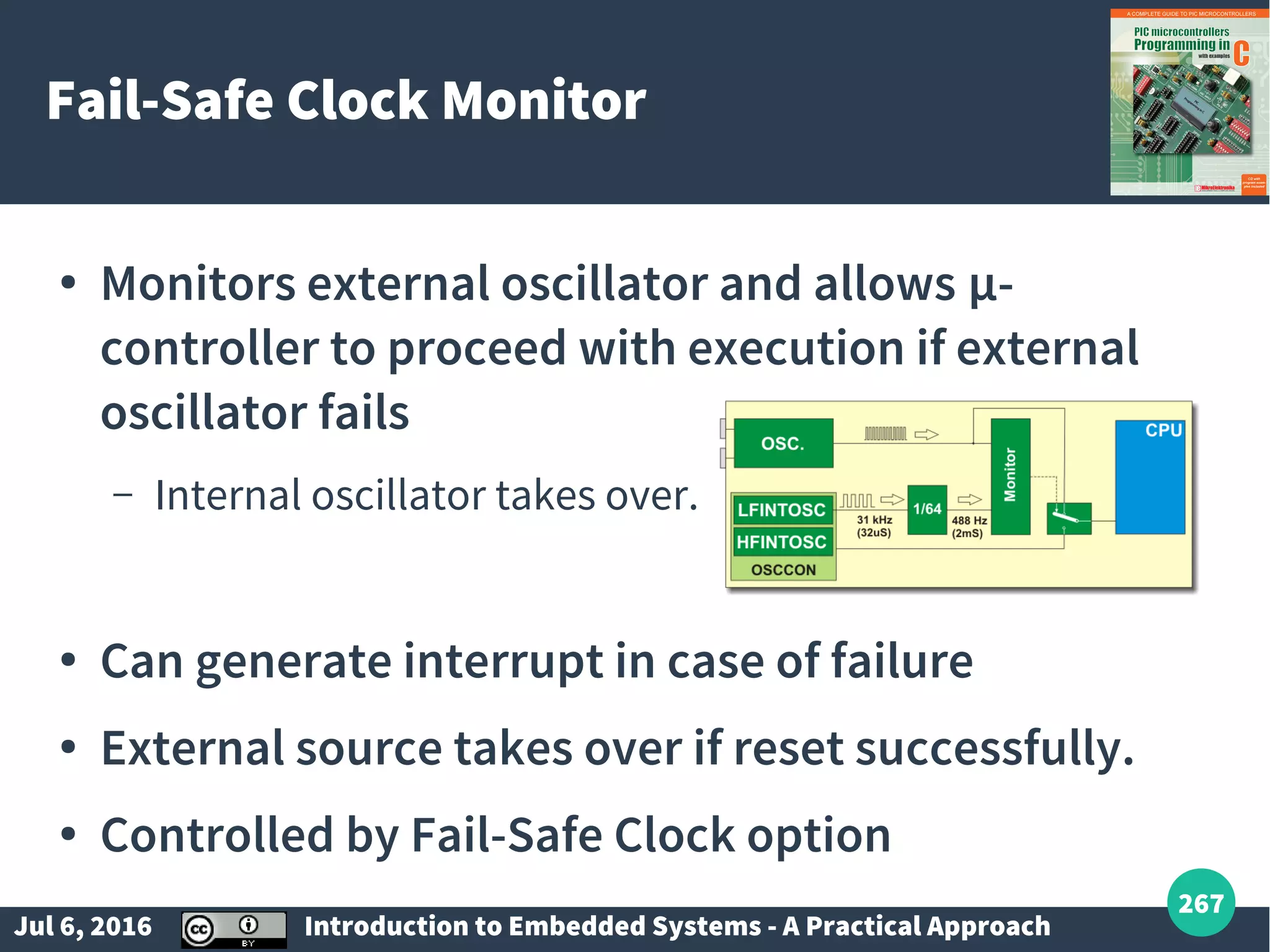
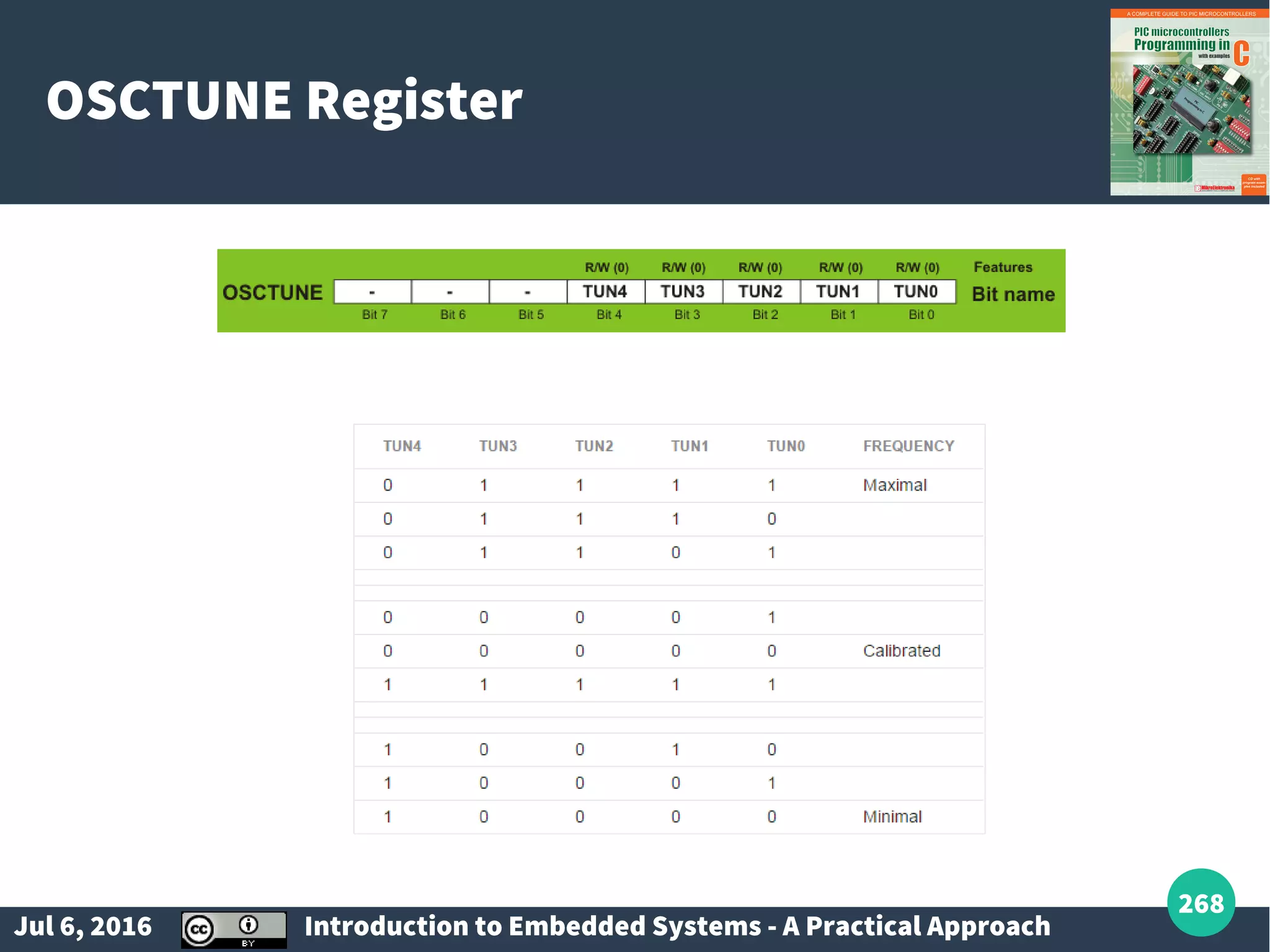
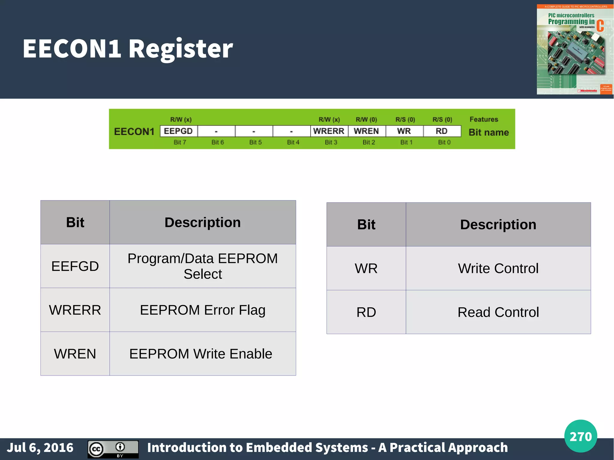
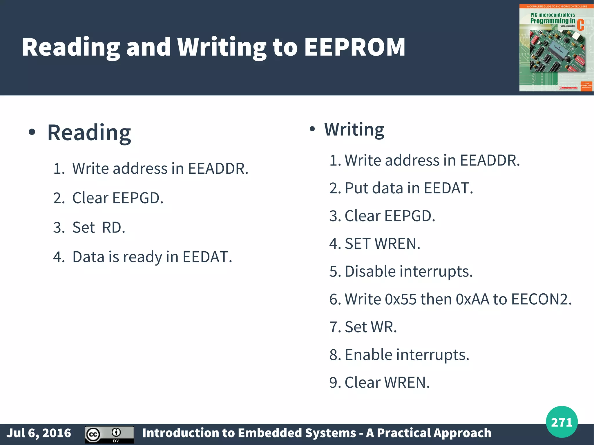
Overview of A/D conversion, EEPROM usage, reset mechanisms, and miscellaneous interfacing techniques.
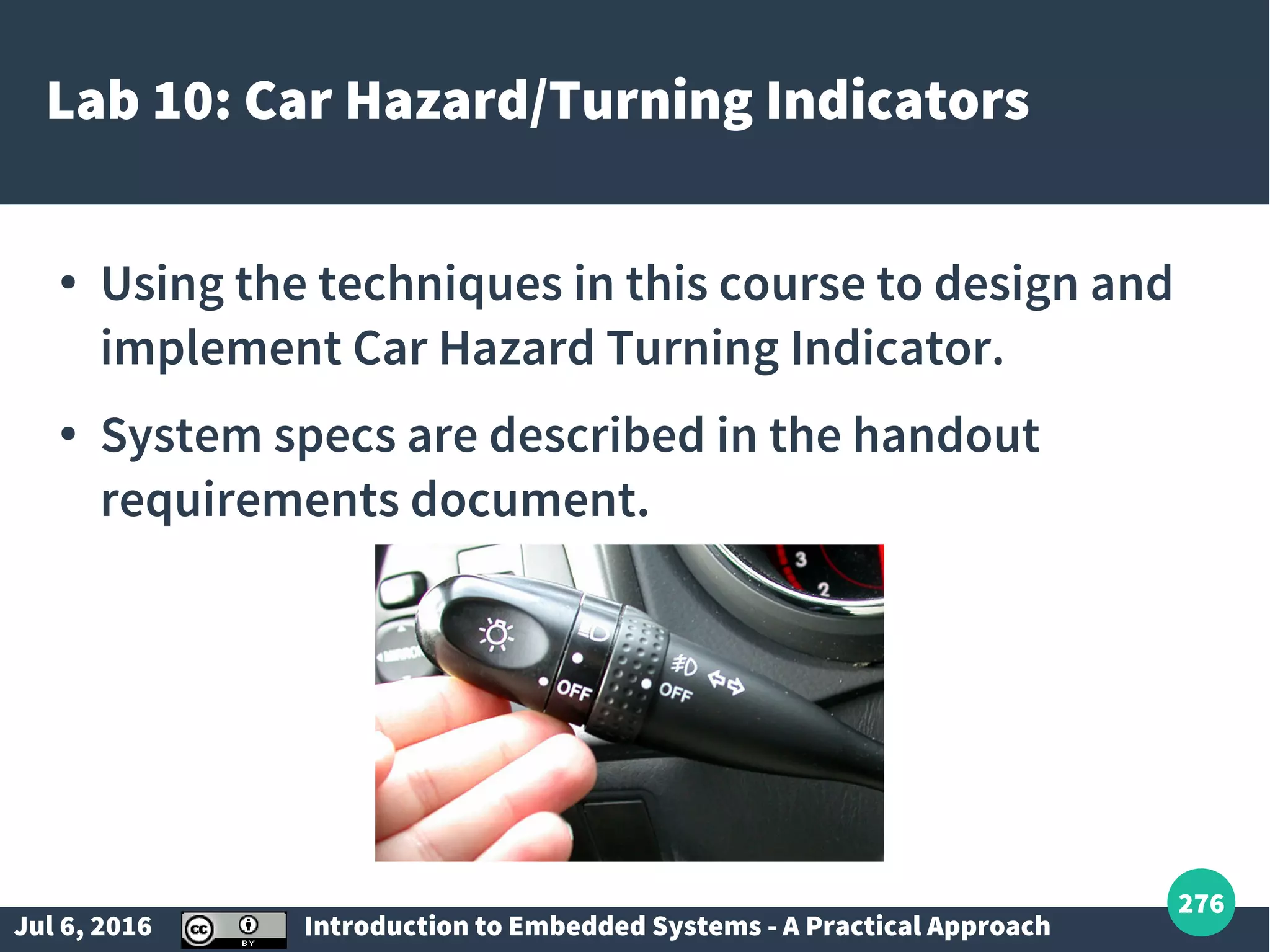
Final project overview on designing Car Hazard/Turning Indicators using concepts learned.