The paper discusses the optimization of edge detection methods for high-resolution images using Verilog, focusing on the Canny and Sobel operators. It highlights improvements in processing time and power consumption compared to previous MATLAB implementations. The proposed system demonstrates effective vehicle detection and medical imaging analysis while requiring fewer resources, paving the way for future applications in FPGA and CPLD technologies.
![International Journal on Cybernetics & Informatics (IJCI) Vol. 5, No. 4, August 2016 367 3. Then Consider the First Pixel, Let’s say “P” 4. For “P”, If G is greater than “T” then move to next Pixel otherwise mark the Pixel as an Edge. 5. Continue the process for overall gradients of all the pixels. The Flow Chart for Sobel Operator is shown below: Sobel Edge detector is compromised in such a way to use a Smoothing filter to increase the noise immunity under certain conditions but it hurts the localization factor. The implementation of Sobel Edge detection algorithm is as follows; Consider we have the image G(c, r), Then Gx is given by Gx= [G(c+1, r-1) +2*G(c+1, r) +G(c+1, r+1)-G(c-1, r+1)-G(c-1, r)-G(c-1, r-1)]; Also Gy is given by Gy= [G(c-1, r-1) +G(c, r-1) +G(c+1, r-1)-G(c-1, r+1)-2*G(c, r+1)-G(c+1, r+1)];](https://image.slidesharecdn.com/5416ijci39-160907071518/75/Enhanced-Optimization-of-Edge-Detection-for-High-Resolution-Images-Using-Verilog-Hardware-Description-Language-with-Low-Power-Consumption-and-Less-Hardware-Technology-5-2048.jpg)

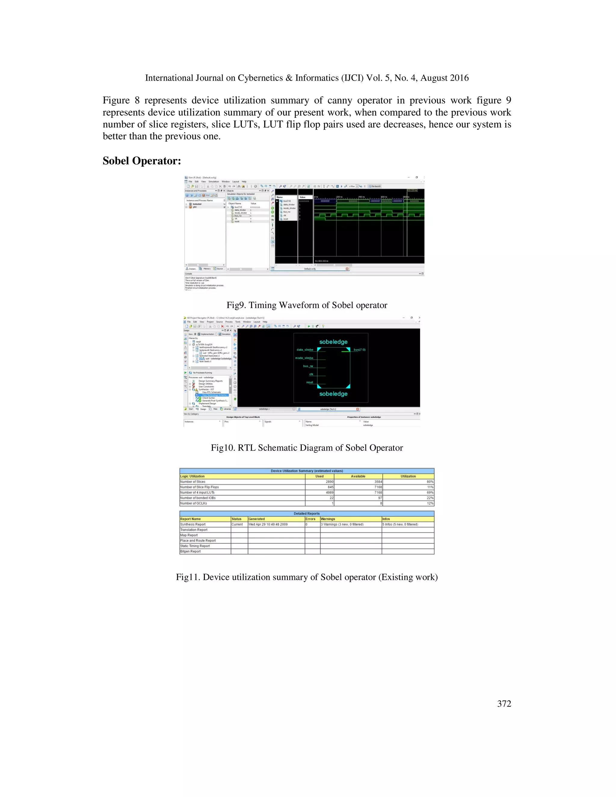
![International Journal on Cybernetics & Informatics (IJCI) Vol. 5, No. 4, August 2016 373 Fig12. Device utilization summary of Sobel operator (Proposed work) From the above figure 10 represents the timing waveforms, figure 11 represents the RTL schematic diagram, figure 12 represents the design utilization summary of Sobel operator. Figure 12 represents device utilization summary of Sobel operator in previous work figure 13 represents device utilization summary of our present work, when compared to the previous work number of slice registers, slice LUTs, LUT flip flop pairs used are decreases, hence our system is better than the previous one. 5. CONCLUSION AND FUTURE SCOPE In our paper, edge detection is done by using three techniques using Verilog module. They are Sobel, canny and prewitt. By using these techniques high end images can also be edge detected in desired fashion by taking Pixel intensity and separate quantization levels. This procedure is very easy when compared to the other modules implemented using mat lab and vhdl and requires less number of flip-flops, logic gates with low power consumption. Future scope: This paper can be implemented on FPGA and CPLD kits and high end images can be edge detected and viewed by using different display devices, which could be a most powerful tool in image processing and visualization techniques. REFERENCES: [1] D. Ziou and S. Tabbone, “Edge detection techniques – an overview,” International Journal of Pattern Recognition and Image Analysis, vol. 8, pp. 537–559, 1998. [2] Chandrashekar N.S, Dr. K.R. Nataraj, “A Distributed Canny Edge Detection and Its Implementation on FPGA” International [3] Tejaswini H.R, Vidhya N, Swathi R Varma, Santhosh B, “An Implementation of Real Time Optimal Edge Detection and VLSI Architecture”. International conference on electronics and communication engineering, 28th april-2013, bengaluru, isbn: 978-93-83060-04-7.](https://image.slidesharecdn.com/5416ijci39-160907071518/75/Enhanced-Optimization-of-Edge-Detection-for-High-Resolution-Images-Using-Verilog-Hardware-Description-Language-with-Low-Power-Consumption-and-Less-Hardware-Technology-11-2048.jpg)