Density Based Traffic Lightcontrol System using Raspberry Pi
The document discusses a density-based traffic light control system using Raspberry Pi and image processing to address urban traffic congestion. It proposes a solution that dynamically adjusts traffic signals based on vehicle density, allowing emergency vehicles to pass more efficiently. The system utilizes hardware components like cameras, IR sensors, and RF transmitters to automate traffic management and improve road safety.
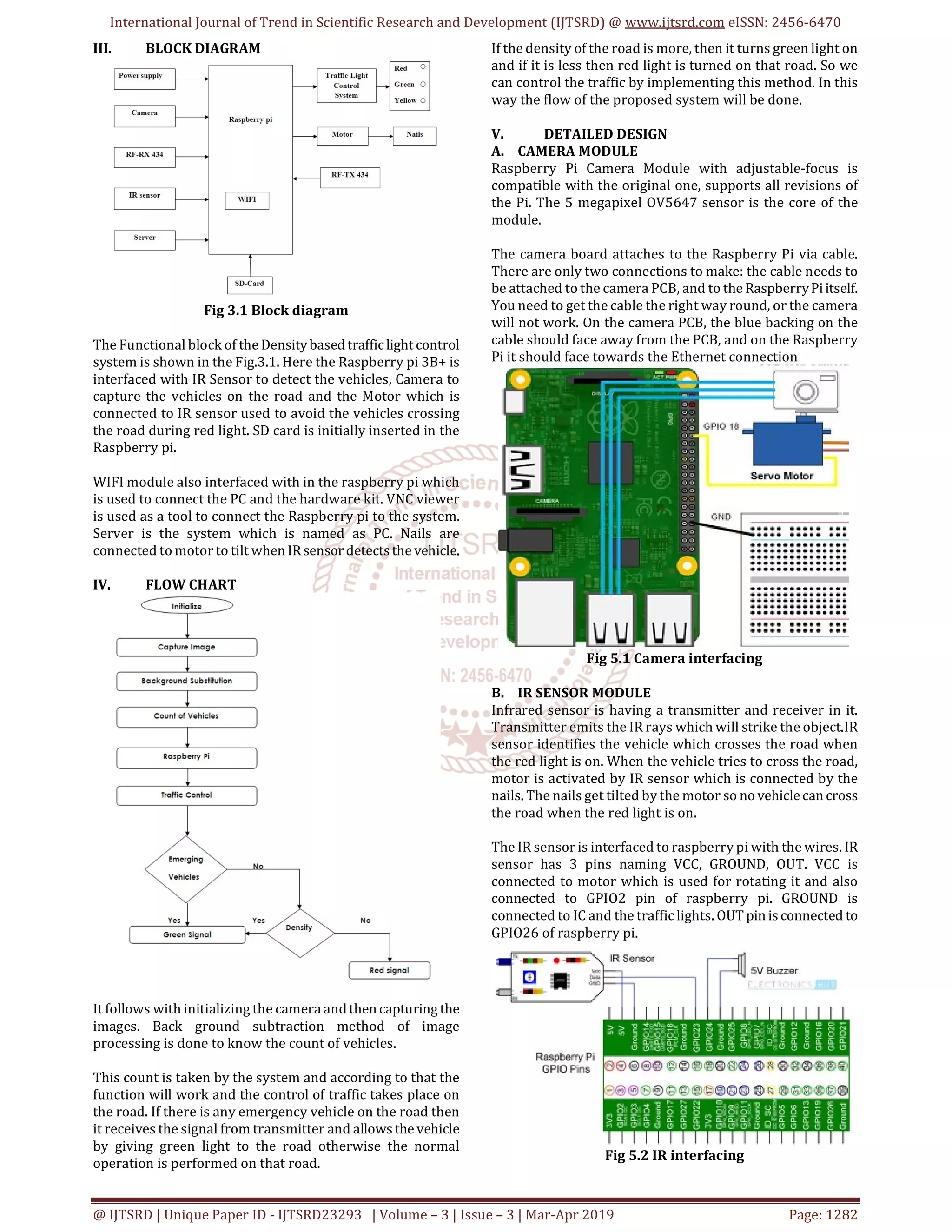
International Journal ofTrend in Scientific Research and Development (IJTSRD) @ www.ijtsrd.com eISSN: 2456-6470 @ IJTSRD | Unique Paper ID - IJTSRD23293 | Volume – 3 | Issue – 3 | Mar-Apr 2019 Page: 1282 III. BLOCK DIAGRAM Fig 3.1 Block diagram The Functional block of theDensitybasedtrafficlight control system is shown in the Fig.3.1. Here the Raspberry pi 3B+ is interfaced with IR Sensor to detect the vehicles, Camera to capture the vehicles on the road and the Motor which is connected to IR sensor used to avoid the vehicles crossing the road during red light. SD card is initially inserted in the Raspberry pi. WIFI module also interfaced with in the raspberry pi which is used to connect the PC and the hardware kit. VNC viewer is used as a tool to connect the Raspberry pi to the system. Server is the system which is named as PC. Nails are connected to motor to tilt when IRsensordetects the vehicle. IV. FLOW CHART It follows with initializing the camera andthen capturing the images. Back ground subtraction method of image processing is done to know the count of vehicles. This count is taken by the system and according to that the function will work and the control of traffic takes place on the road. If there is any emergency vehicle on the road then it receives the signal from transmitter and allows the vehicle by giving green light to the road otherwise the normal operation is performed on that road. If the density of the road is more, then it turns green light on and if it is less then red light is turned on that road. So we can control the traffic by implementing this method. In this way the flow of the proposed system will be done. V. DETAILED DESIGN A. CAMERA MODULE Raspberry Pi Camera Module with adjustable-focus is compatible with the original one, supports all revisions of the Pi. The 5 megapixel OV5647 sensor is the core of the module. The camera board attaches to the Raspberry Pi via cable. There are only two connections to make: the cable needs to be attached to the camera PCB, and to the RaspberryPiitself. You need to get the cable the right way round, or the camera will not work. On the camera PCB, the blue backing on the cable should face away from the PCB, and on the Raspberry Pi it should face towards the Ethernet connection Fig 5.1 Camera interfacing B. IR SENSOR MODULE Infrared sensor is having a transmitter and receiver in it. Transmitter emits the IR rays which will strike the object.IR sensor identifies the vehicle which crosses the road when the red light is on. When the vehicle tries to cross the road, motor is activated by IR sensor which is connected by the nails. The nails get tilted bythe motor so no vehiclecan cross the road when the red light is on. The IR sensor is interfaced to raspberry pi with the wires. IR sensor has 3 pins naming VCC, GROUND, OUT. VCC is connected to motor which is used for rotating it and also connected to GPIO2 pin of raspberry pi. GROUND is connected to IC and the traffic lights. OUTpin is connected to GPIO26 of raspberry pi. Fig 5.2 IR interfacing
3.
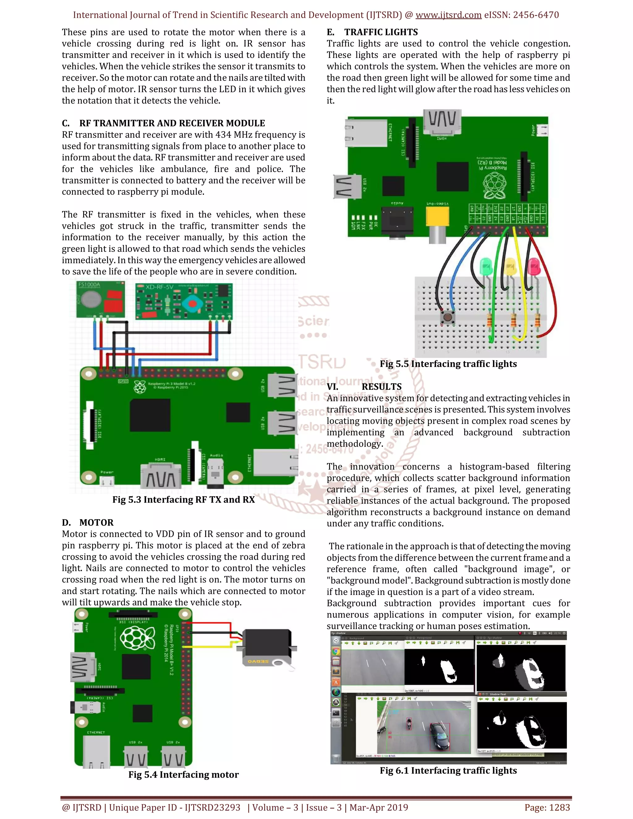
International Journal ofTrend in Scientific Research and Development (IJTSRD) @ www.ijtsrd.com eISSN: 2456-6470 @ IJTSRD | Unique Paper ID - IJTSRD23293 | Volume – 3 | Issue – 3 | Mar-Apr 2019 Page: 1283 These pins are used to rotate the motor when there is a vehicle crossing during red is light on. IR sensor has transmitter and receiver in it which is used to identify the vehicles. When the vehicle strikes the sensor it transmits to receiver. So the motor can rotate and the nails aretiltedwith the help of motor. IR sensor turns the LED in it which gives the notation that it detects the vehicle. C. RF TRANMITTER AND RECEIVER MODULE RF transmitter and receiver are with 434 MHz frequency is used for transmitting signals from place to another place to inform about the data. RF transmitter and receiver are used for the vehicles like ambulance, fire and police. The transmitter is connected to battery and the receiver will be connected to raspberry pi module. The RF transmitter is fixed in the vehicles, when these vehicles got struck in the traffic, transmitter sends the information to the receiver manually, by this action the green light is allowed to that road which sends the vehicles immediately. In this way the emergencyvehicles are allowed to save the life of the people who are in severe condition. Fig 5.3 Interfacing RF TX and RX D. MOTOR Motor is connected to VDD pin of IR sensor and to ground pin raspberry pi. This motor is placed at the end of zebra crossing to avoid the vehicles crossing the road during red light. Nails are connected to motor to control the vehicles crossing road when the red light is on. The motor turns on and start rotating. The nails which are connected to motor will tilt upwards and make the vehicle stop. Fig 5.4 Interfacing motor E. TRAFFIC LIGHTS Traffic lights are used to control the vehicle congestion. These lights are operated with the help of raspberry pi which controls the system. When the vehicles are more on the road then green light will be allowed for some time and then the red light will glow after the roadhas less vehicles on it. Fig 5.5 Interfacing traffic lights VI. RESULTS An innovative system for detectingandextractingvehicles in traffic surveillance scenes is presented.This system involves locating moving objects present in complex road scenes by implementing an advanced background subtraction methodology. The innovation concerns a histogram-based filtering procedure, which collects scatter background information carried in a series of frames, at pixel level, generating reliable instances of the actual background. The proposed algorithm reconstructs a background instance on demand under any traffic conditions. The rationale in the approach is that of detectingthemoving objects from the difference between the current frameand a reference frame, often called "background image", or "background model".Background subtraction is mostlydone if the image in question is a part of a video stream. Background subtraction provides important cues for numerous applications in computer vision, for example surveillance tracking or human poses estimation. Fig 6.1 Interfacing traffic lights
4.
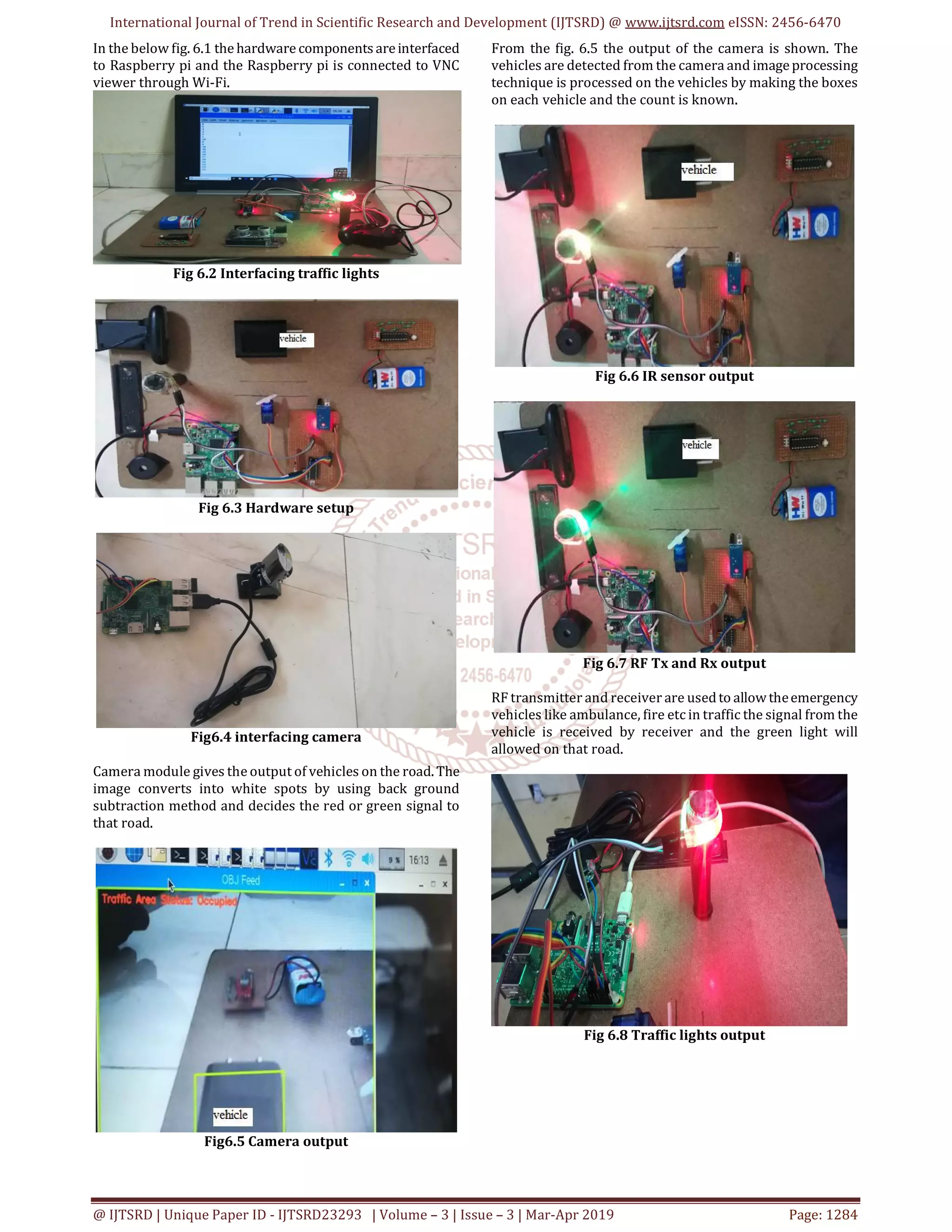
International Journal ofTrend in Scientific Research and Development (IJTSRD) @ www.ijtsrd.com eISSN: 2456-6470 @ IJTSRD | Unique Paper ID - IJTSRD23293 | Volume – 3 | Issue – 3 | Mar-Apr 2019 Page: 1284 In the below fig. 6.1 the hardware components areinterfaced to Raspberry pi and the Raspberry pi is connected to VNC viewer through Wi-Fi. Fig 6.2 Interfacing traffic lights Fig 6.3 Hardware setup Fig6.4 interfacing camera Camera module gives the output of vehicles on the road. The image converts into white spots by using back ground subtraction method and decides the red or green signal to that road. Fig6.5 Camera output From the fig. 6.5 the output of the camera is shown. The vehicles are detected from the camera and imageprocessing technique is processed on the vehicles by making the boxes on each vehicle and the count is known. Fig 6.6 IR sensor output Fig 6.7 RF Tx and Rx output RF transmitter and receiver are usedto allowtheemergency vehicles like ambulance, fire etc in traffic the signal from the vehicle is received by receiver and the green light will allowed on that road. Fig 6.8 Traffic lights output
5.
International Journal ofTrend in Scientific Research and Development (IJTSRD) @ www.ijtsrd.com eISSN: 2456-6470 @ IJTSRD | Unique Paper ID - IJTSRD23293 | Volume – 3 | Issue – 3 | Mar-Apr 2019 Page: 1285 Fig 6.9 Entire output CONCLUSION In accordance with the traffic congestion in urban areas, we designed a density based traffic control system by using Raspberry pi, IR sensor, Camera module, Image processing. The camera module is installed at the starting of the road. This gives the count of vehicles on the road, with the help of that count we can control the traffic by allowing the vehicles where the density is more. The system provides better flexibility to manage the traffic. The information about the ambulance is also known by transmitting the signal and will be displayed green light on the road. When the vehicle tries to cross the road during red light, it will get damaged by the nails connected to motor. Density based traffic light controlsystemisproductiveand it reduces the traffic in urban areas, time consumption due to heavy traffic. REFERENCES [1] 2015 International Conference on Computers, Communications, and Systems by Y M Jagadeesh ; G. Merlin Suba ; S Karthik ; K Yokesh [2] 2015 International Conference on Electrical Engineering and Information Communication Technology (ICEEICT) by Mohammad Shahab Uddin ; Ayon Kumar Das ; Md. Abu Taleb [3] 2016 Third International Conference on Electrical, Electronics, Computer Engineering and their Applications (EECEA) byBilal Ghazal ; KhaledElKhatib ; Khaled Chahine ; Mohamad Kherfan [4] 2017 International Conference on Inventive Computing and Informatics (ICICI)2017byR.Bhargavi Devi ; D. Kavya Reddy ; E. Sravani ; Gaddam Srujan ; Shiv Shankar ; Shubhro Chakrabartty [5] 2017 1st International Conference on Intelligent Systems and Information Management (ICISIM) Year:2017 Authors: Swapnil Manohar Shinde [6] 2017 International Conference on Energy, Communication, Data Analytics and Soft Computing (ICECDS);Conference: 1-2 Aug. 2017 Date Added to IEEE Xplore: 21 June 2018 Authors: Elizabeth Basil,Prof.S.D.Sawant [7] 2017 3rd International Conference on Electrical Information and Communication Technology (EICT) byTaqi Tahmid ; Eklas Hossain [8] https://www.researchgate.net/publication/32327953 1_An_IoT_based_Intelligent_Traffic_Congestion_Control _System_for_Road_Crossings by Pampa Sadhukhan, Firoj Gazi [9] https://www.researchgate.net/publication/30121453 6_IoT_Based_Dynamic_Road_Traffic_Management_for_S mart_Cities [accessed Sep 11 2018]. [10] https://www.ijecs.in/index.php/ijecs/article/view/24 76 Online Traffic Light Control System G. Karthika S. Prabhu Ram, ArticleDatePublished:15February2017 [11] https://www.ripublication.com/ijaer17/ijaerv12n19_ 37.pdf Ashok.P.V B.Tech Graduate, Department of Information Technology, SRM University, Kattankaluthur Campus, Chennai-603203, India. [12] http://www.ijareeie.com/upload/2018/january/14_IO T.pdf by Dr.Sanjeev Sharma, Vaishnavi Giradkar ,Aarti Sanap,Snehal Sarolka [13] http://thesai.org/Downloads/Volume6No2/Paper6Int elligent_Traffic_Information_System_Based.pdf -Hasan Omar Al-Sakran
![International Journal of Trend in Scientific Research and Development (IJTSRD) @ www.ijtsrd.com eISSN: 2456-6470 @ IJTSRD | Unique Paper ID - IJTSRD23293 | Volume – 3 | Issue – 3 | Mar-Apr 2019 Page: 1285 Fig 6.9 Entire output CONCLUSION In accordance with the traffic congestion in urban areas, we designed a density based traffic control system by using Raspberry pi, IR sensor, Camera module, Image processing. The camera module is installed at the starting of the road. This gives the count of vehicles on the road, with the help of that count we can control the traffic by allowing the vehicles where the density is more. The system provides better flexibility to manage the traffic. The information about the ambulance is also known by transmitting the signal and will be displayed green light on the road. When the vehicle tries to cross the road during red light, it will get damaged by the nails connected to motor. Density based traffic light controlsystemisproductiveand it reduces the traffic in urban areas, time consumption due to heavy traffic. REFERENCES [1] 2015 International Conference on Computers, Communications, and Systems by Y M Jagadeesh ; G. Merlin Suba ; S Karthik ; K Yokesh [2] 2015 International Conference on Electrical Engineering and Information Communication Technology (ICEEICT) by Mohammad Shahab Uddin ; Ayon Kumar Das ; Md. Abu Taleb [3] 2016 Third International Conference on Electrical, Electronics, Computer Engineering and their Applications (EECEA) byBilal Ghazal ; KhaledElKhatib ; Khaled Chahine ; Mohamad Kherfan [4] 2017 International Conference on Inventive Computing and Informatics (ICICI)2017byR.Bhargavi Devi ; D. Kavya Reddy ; E. Sravani ; Gaddam Srujan ; Shiv Shankar ; Shubhro Chakrabartty [5] 2017 1st International Conference on Intelligent Systems and Information Management (ICISIM) Year:2017 Authors: Swapnil Manohar Shinde [6] 2017 International Conference on Energy, Communication, Data Analytics and Soft Computing (ICECDS);Conference: 1-2 Aug. 2017 Date Added to IEEE Xplore: 21 June 2018 Authors: Elizabeth Basil,Prof.S.D.Sawant [7] 2017 3rd International Conference on Electrical Information and Communication Technology (EICT) byTaqi Tahmid ; Eklas Hossain [8] https://www.researchgate.net/publication/32327953 1_An_IoT_based_Intelligent_Traffic_Congestion_Control _System_for_Road_Crossings by Pampa Sadhukhan, Firoj Gazi [9] https://www.researchgate.net/publication/30121453 6_IoT_Based_Dynamic_Road_Traffic_Management_for_S mart_Cities [accessed Sep 11 2018]. [10] https://www.ijecs.in/index.php/ijecs/article/view/24 76 Online Traffic Light Control System G. Karthika S. Prabhu Ram, ArticleDatePublished:15February2017 [11] https://www.ripublication.com/ijaer17/ijaerv12n19_ 37.pdf Ashok.P.V B.Tech Graduate, Department of Information Technology, SRM University, Kattankaluthur Campus, Chennai-603203, India. [12] http://www.ijareeie.com/upload/2018/january/14_IO T.pdf by Dr.Sanjeev Sharma, Vaishnavi Giradkar ,Aarti Sanap,Snehal Sarolka [13] http://thesai.org/Downloads/Volume6No2/Paper6Int elligent_Traffic_Information_System_Based.pdf -Hasan Omar Al-Sakran](https://image.slidesharecdn.com/276densitybasedtrafficlightcontrolsystemusingraspberrypi-190619120359/75/Density-Based-Traffic-Lightcontrol-System-using-Raspberry-Pi-5-2048.jpg)