Download as PDF, PPTX

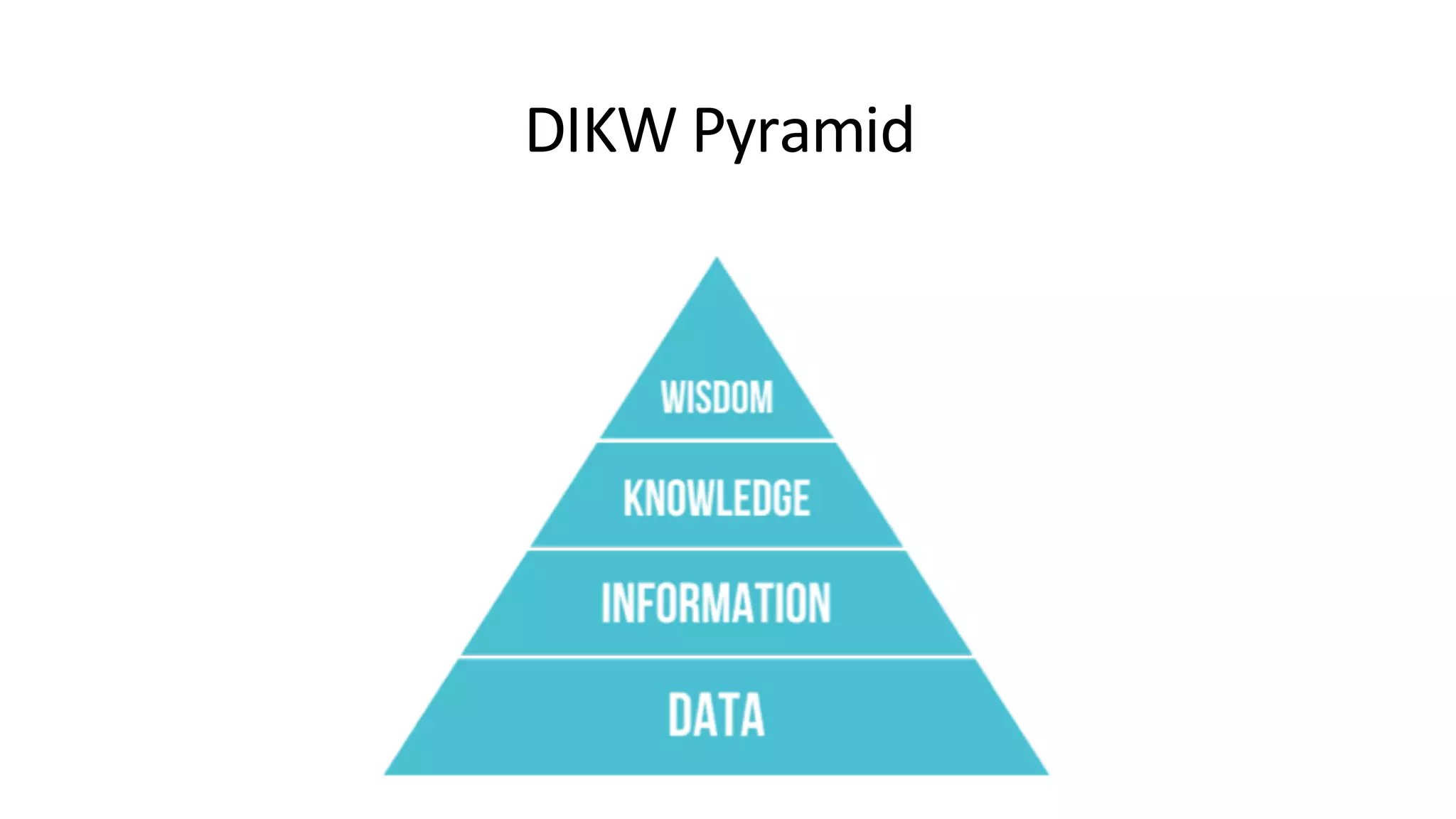
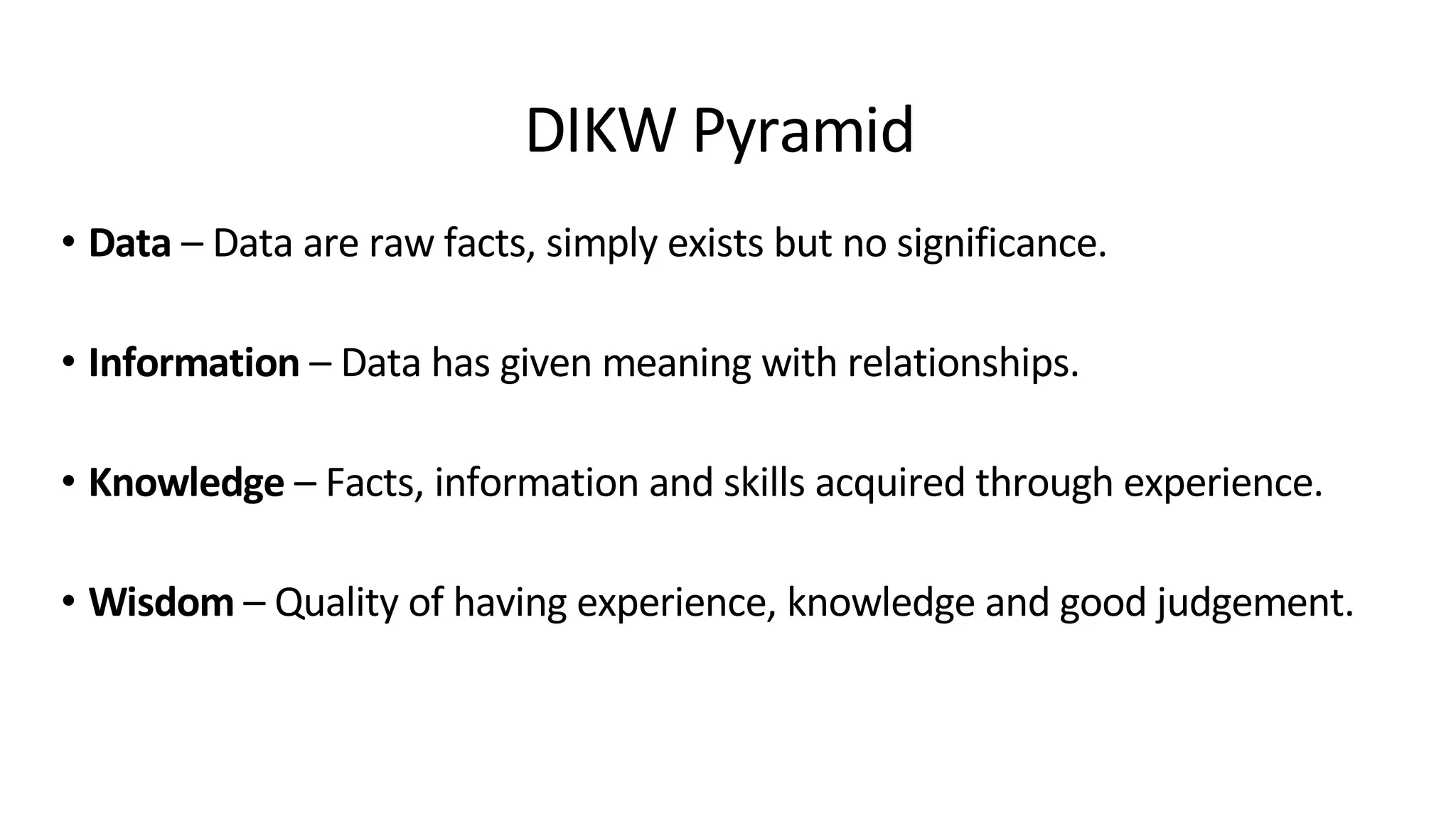
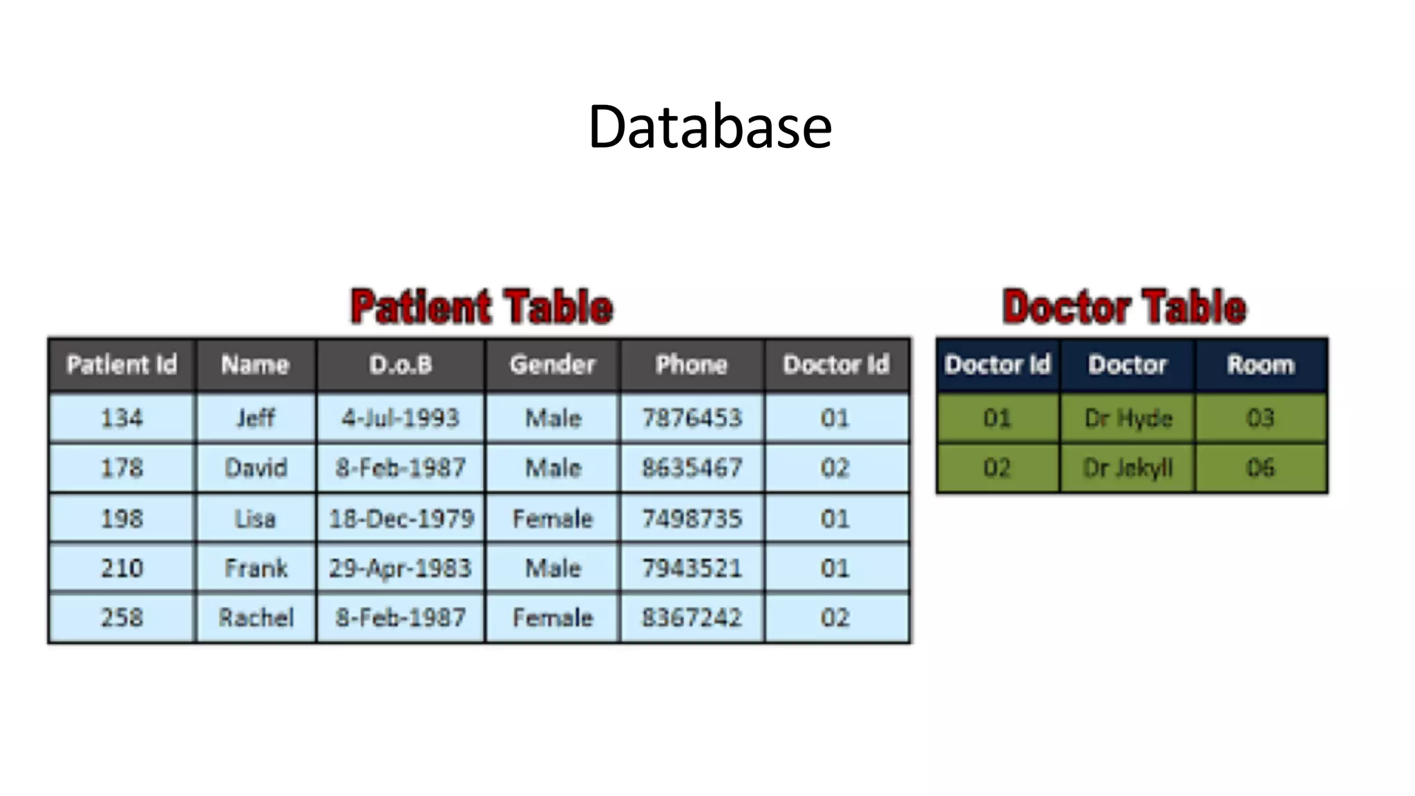

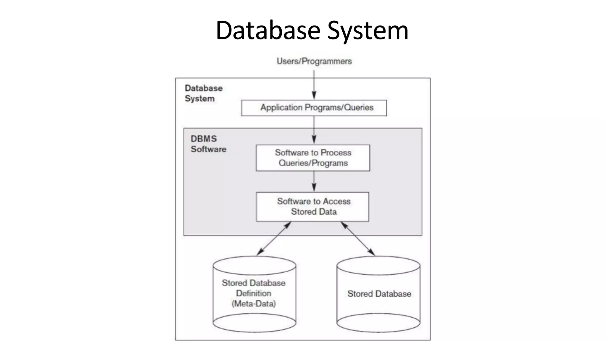

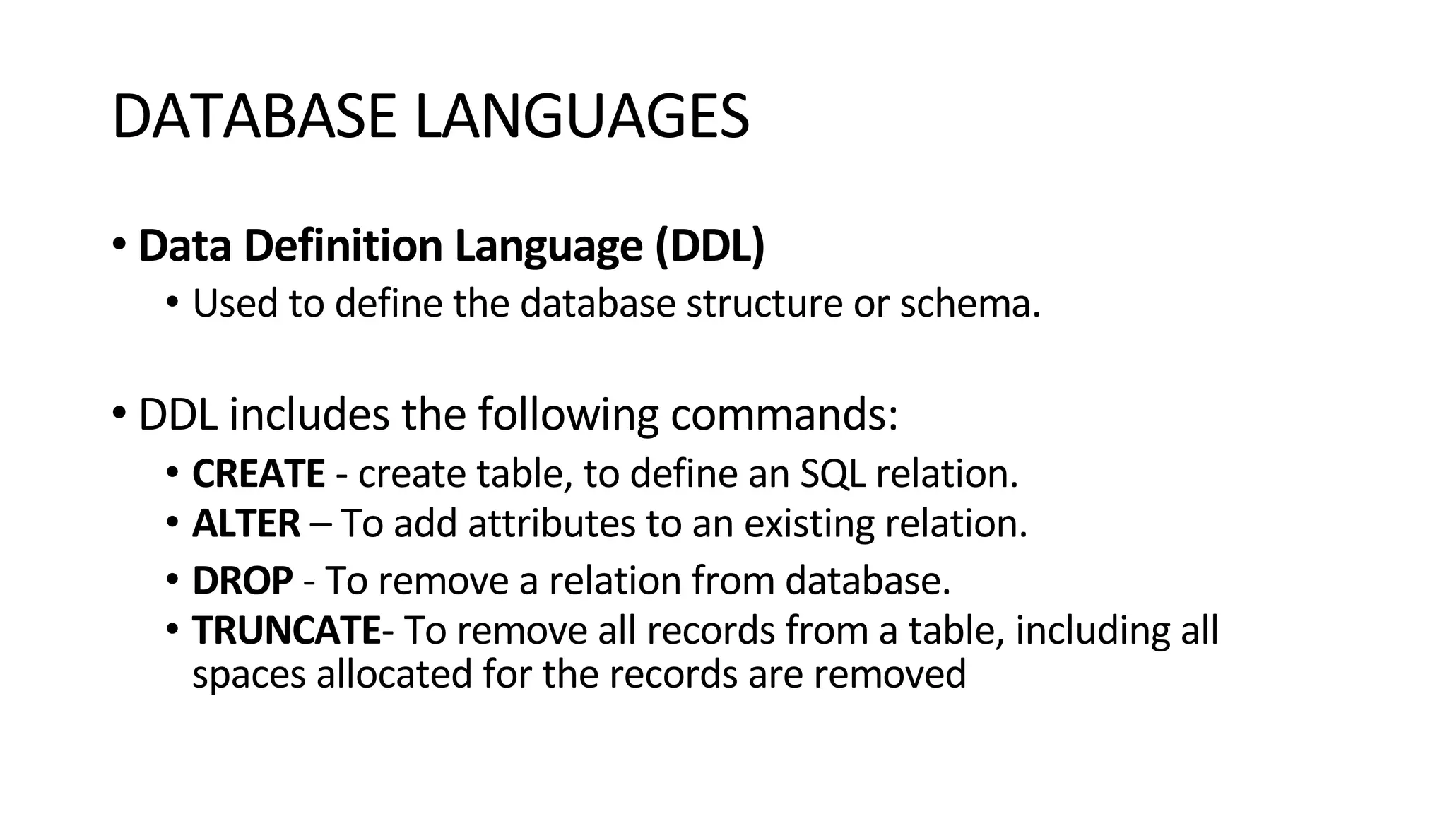
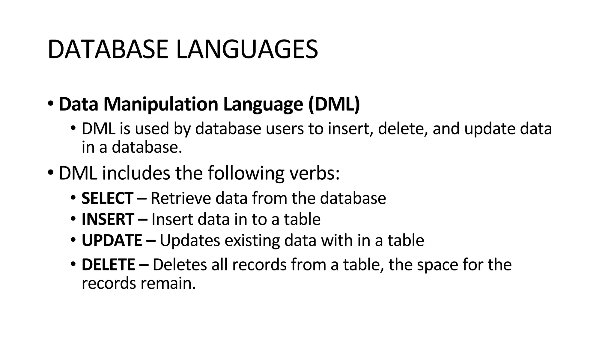
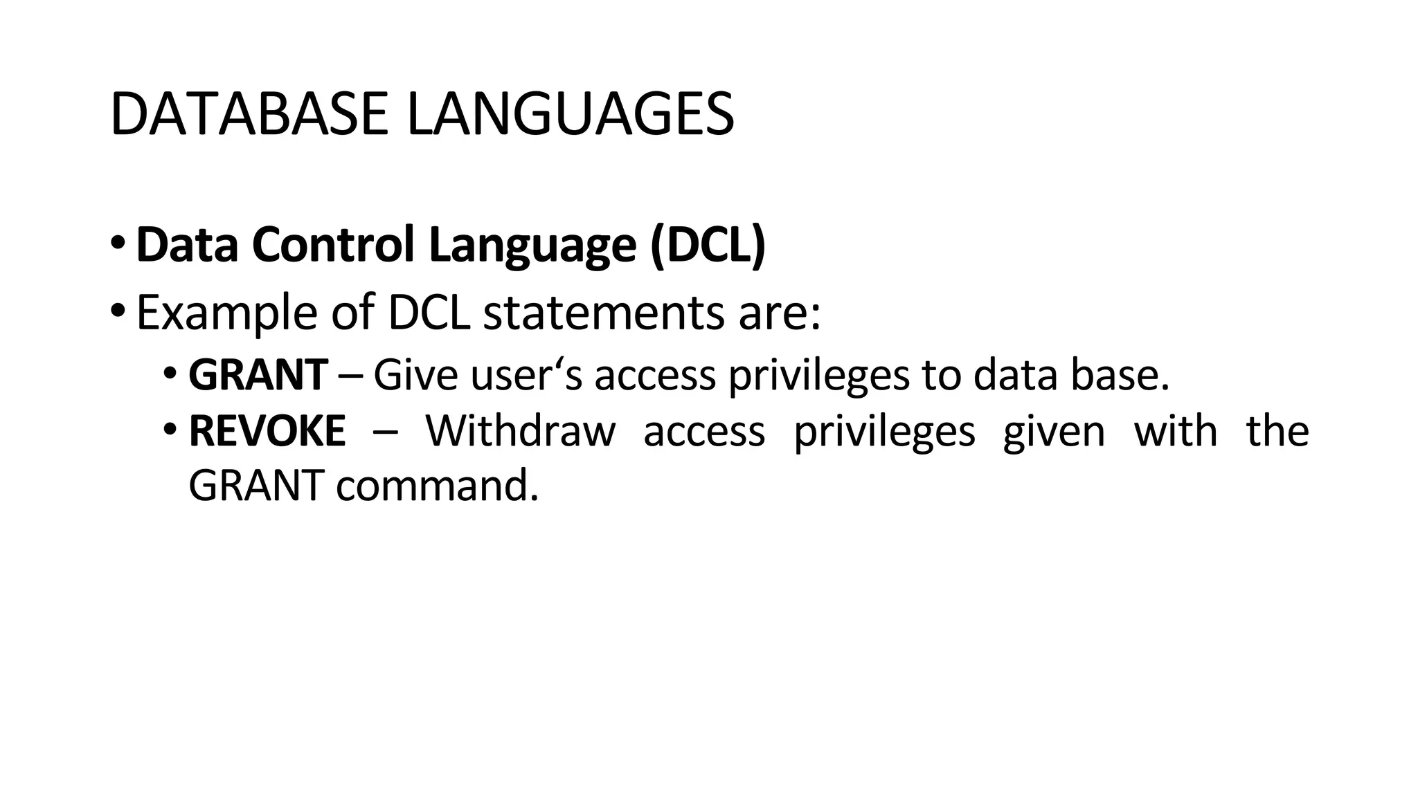


This document provides an overview of key concepts in database management systems including: 1) It describes the DIKW pyramid which organizes data, information, knowledge, and wisdom. 2) It explains what a database is and the role of a database management system (DBMS) in handling data storage, retrieval, and updates. 3) It provides examples of database systems and languages used including structured query language (SQL) and its components for data definition, manipulation, and control.