Downloaded 10 times
![DATA TRANSFER INSTRUCTIONS MOV- Move Usage: MOV destination, source This instruction is for copying the source content to the destination data types of source and destination should be match- either bytes or word MOV AX,CX ; copy CX to AX- word operation MOV AL,AH ; copy AH to AL- byte operation MOV AX,[BX] ;copy into AX the data in the address pointed by BX MOV COST,DX ; copy the word in DX to the location labeled COST](https://image.slidesharecdn.com/chapter3-programmingconcepts-ii-170612053818/75/Chapter-3-programming-concepts-ii-11-2048.jpg)
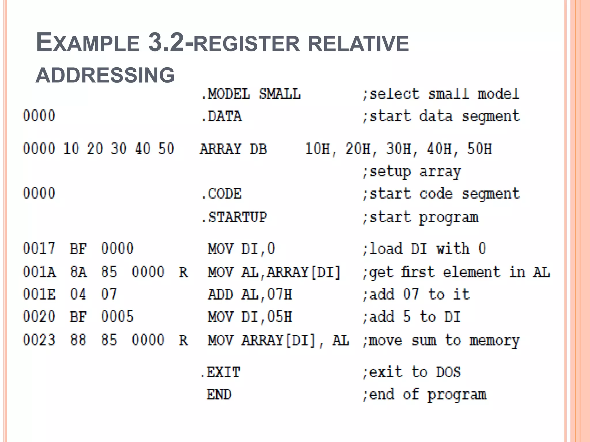
![ DS is first initialized with 5 bytes address of the first location is labeled as ARRAY DI is used to address the element numbers (with DI=0 1st element is accessed, DI=5 last element) EA will be [Array + DI] When DI=0, it will be Mov AL, Array[DI] Add 07, with DI=5 Array[DI] becomes address of the sixth location in memory](https://image.slidesharecdn.com/chapter3-programmingconcepts-ii-170612053818/75/Chapter-3-programming-concepts-ii-17-2048.jpg)
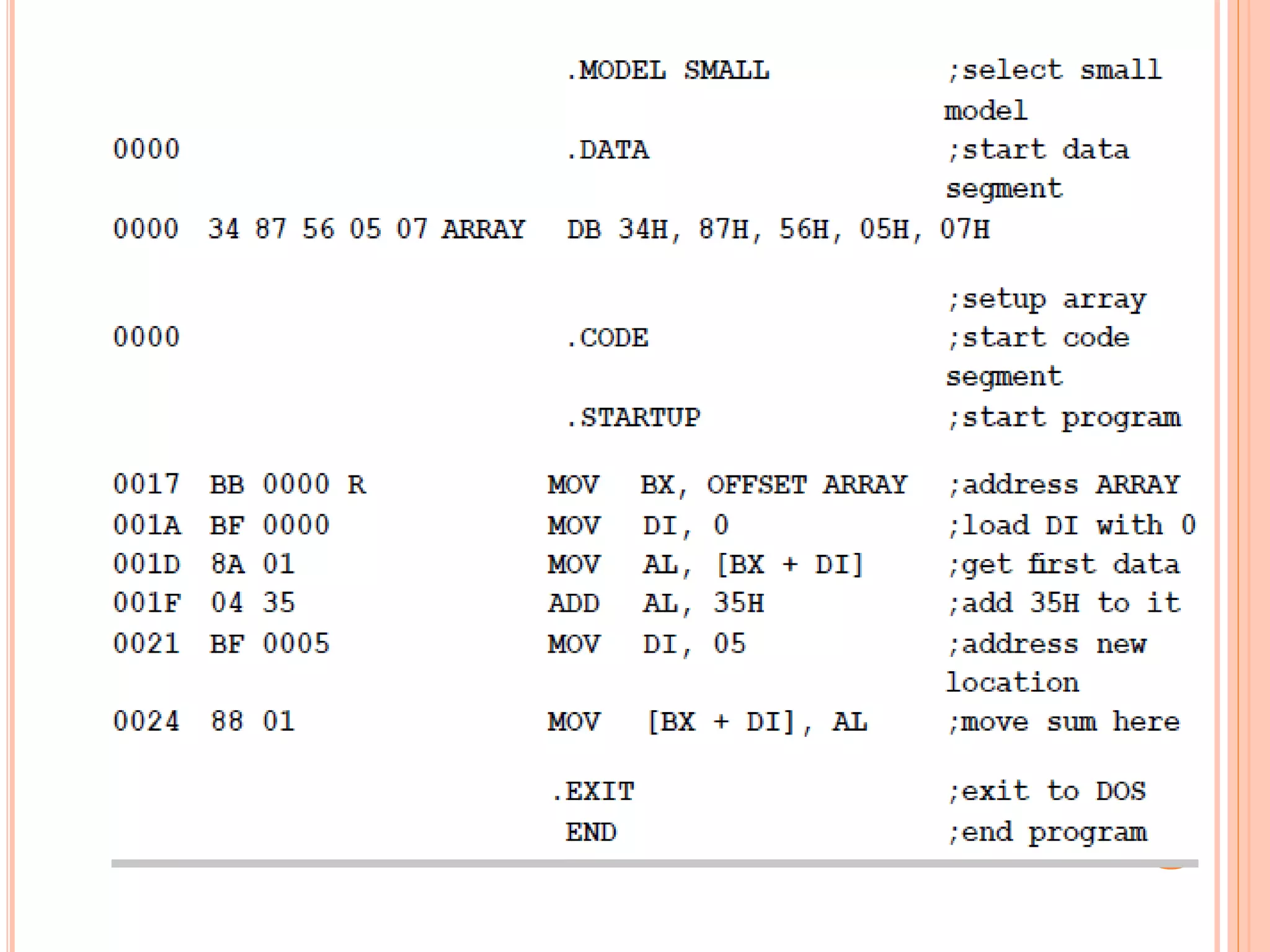
![ uses base indexed mode of addressing EA= base reg + index Reg MOV BX, offset array causes the offset of Array to be loaded into BX BX is now a pointer to the location labeled Array to point each element one by one, another register DI is also used With DI=o, the instruction MOV AL, [BX+DI] causes the data in the first location to be copied to AL with DI=5, [BX+DI] access the sixth location in the data segment](https://image.slidesharecdn.com/chapter3-programmingconcepts-ii-170612053818/75/Chapter-3-programming-concepts-ii-19-2048.jpg)
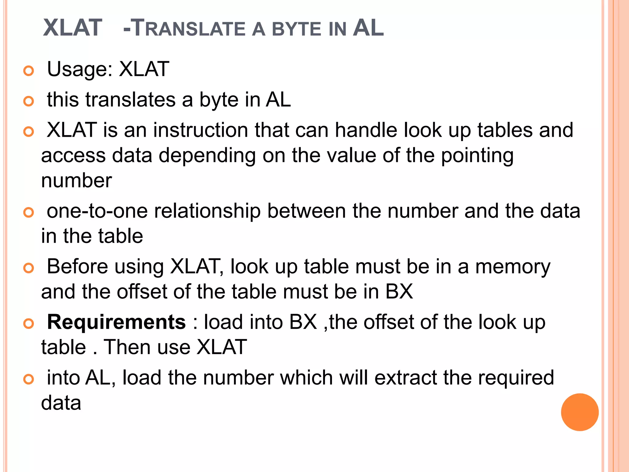
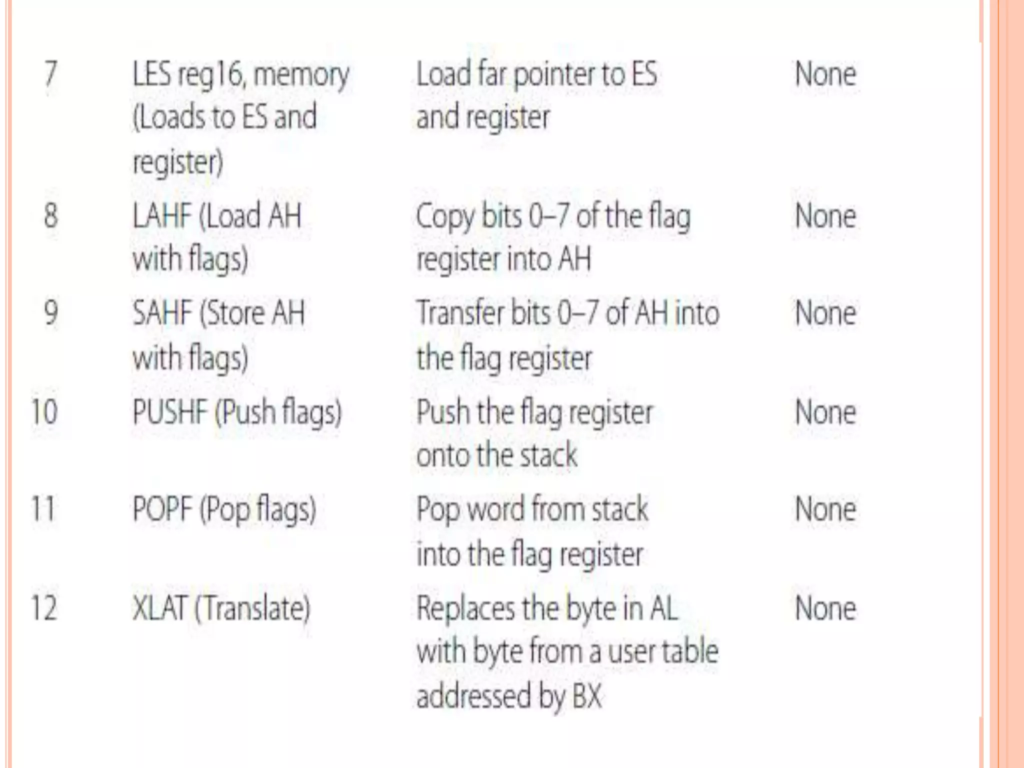
![ XLAT is equivalent to the following instructions: MOV AX, 0 MOV SI, 0 MOV AL, [BX + SI] SI or DI will be okay for showing the equivalence.](https://image.slidesharecdn.com/chapter3-programmingconcepts-ii-170612053818/75/Chapter-3-programming-concepts-ii-27-2048.jpg)
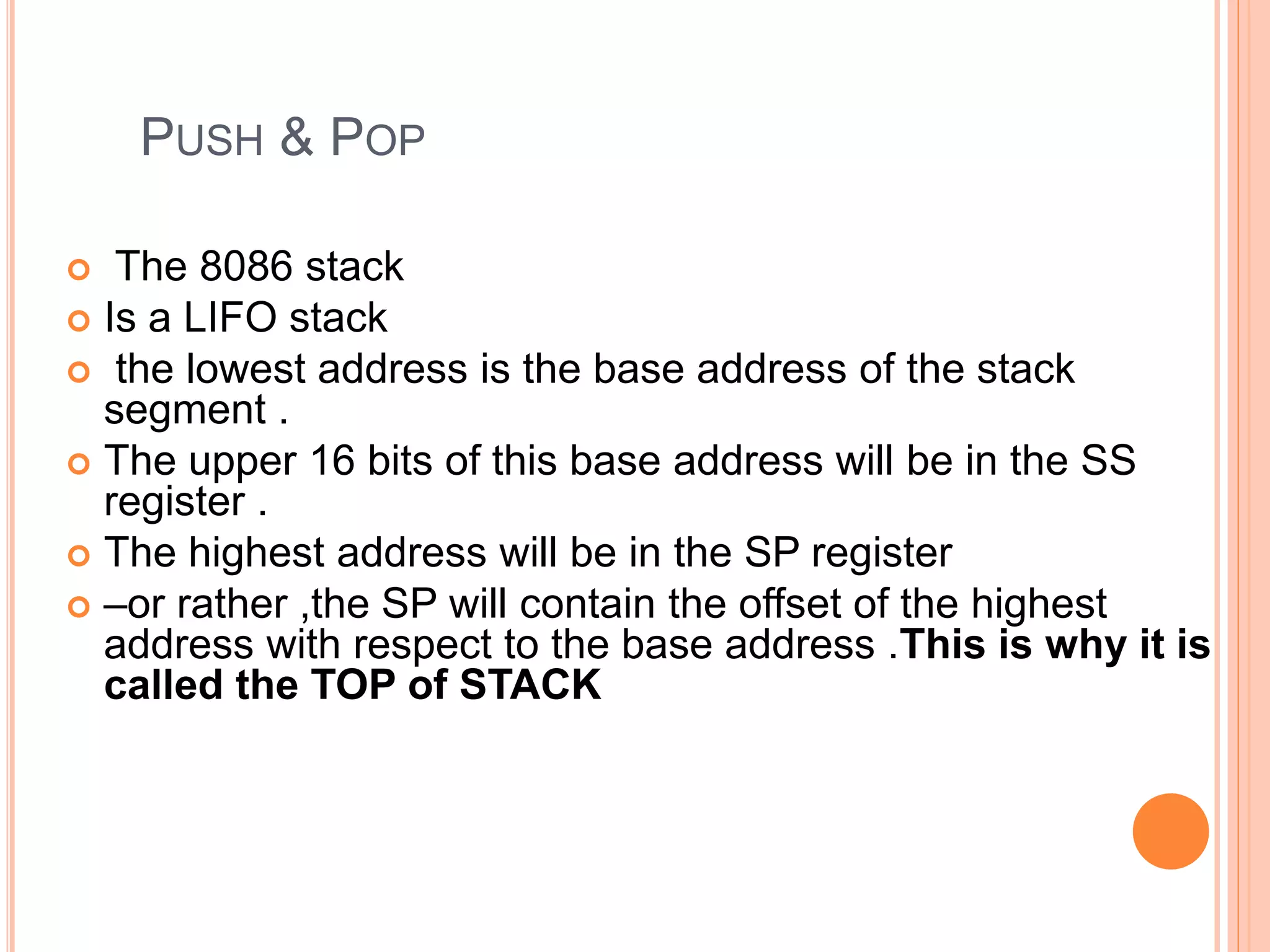
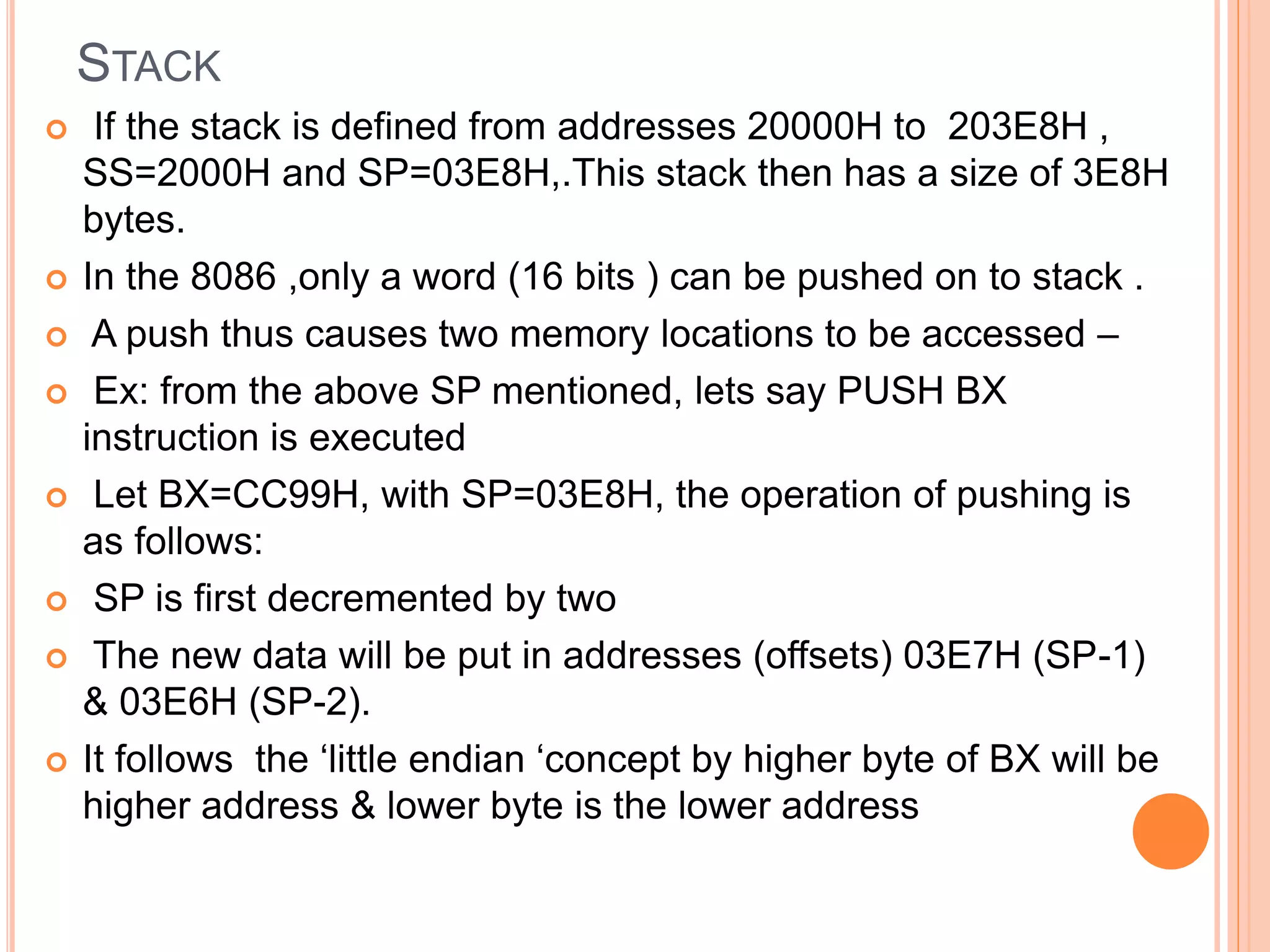
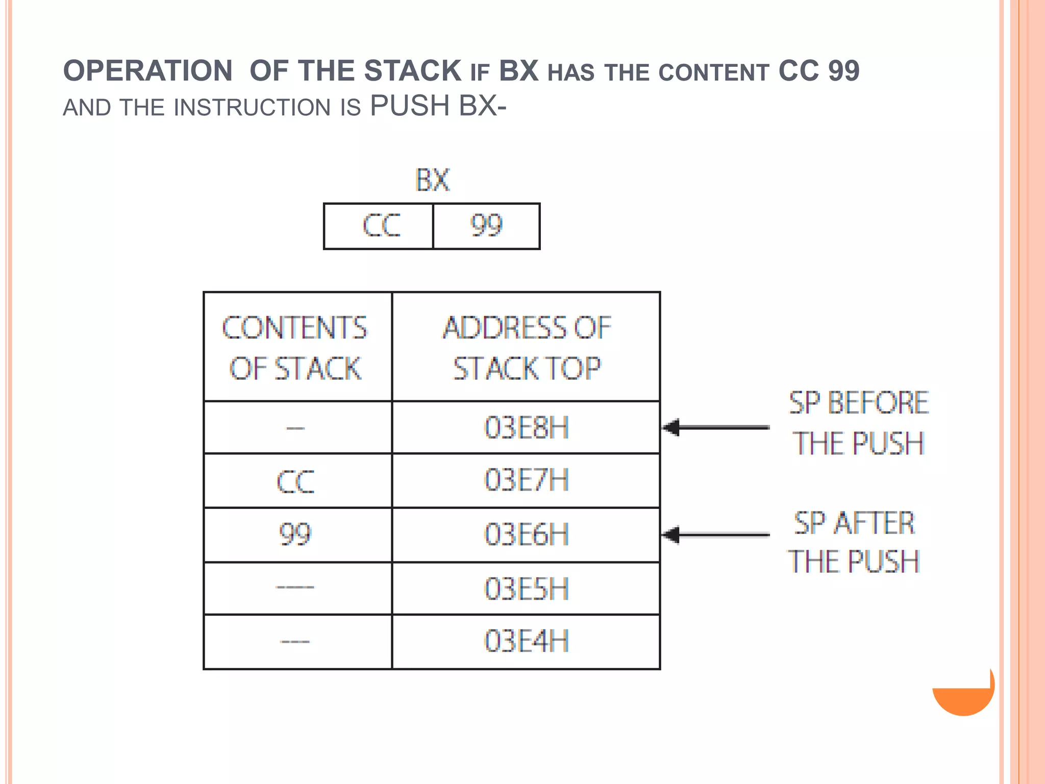
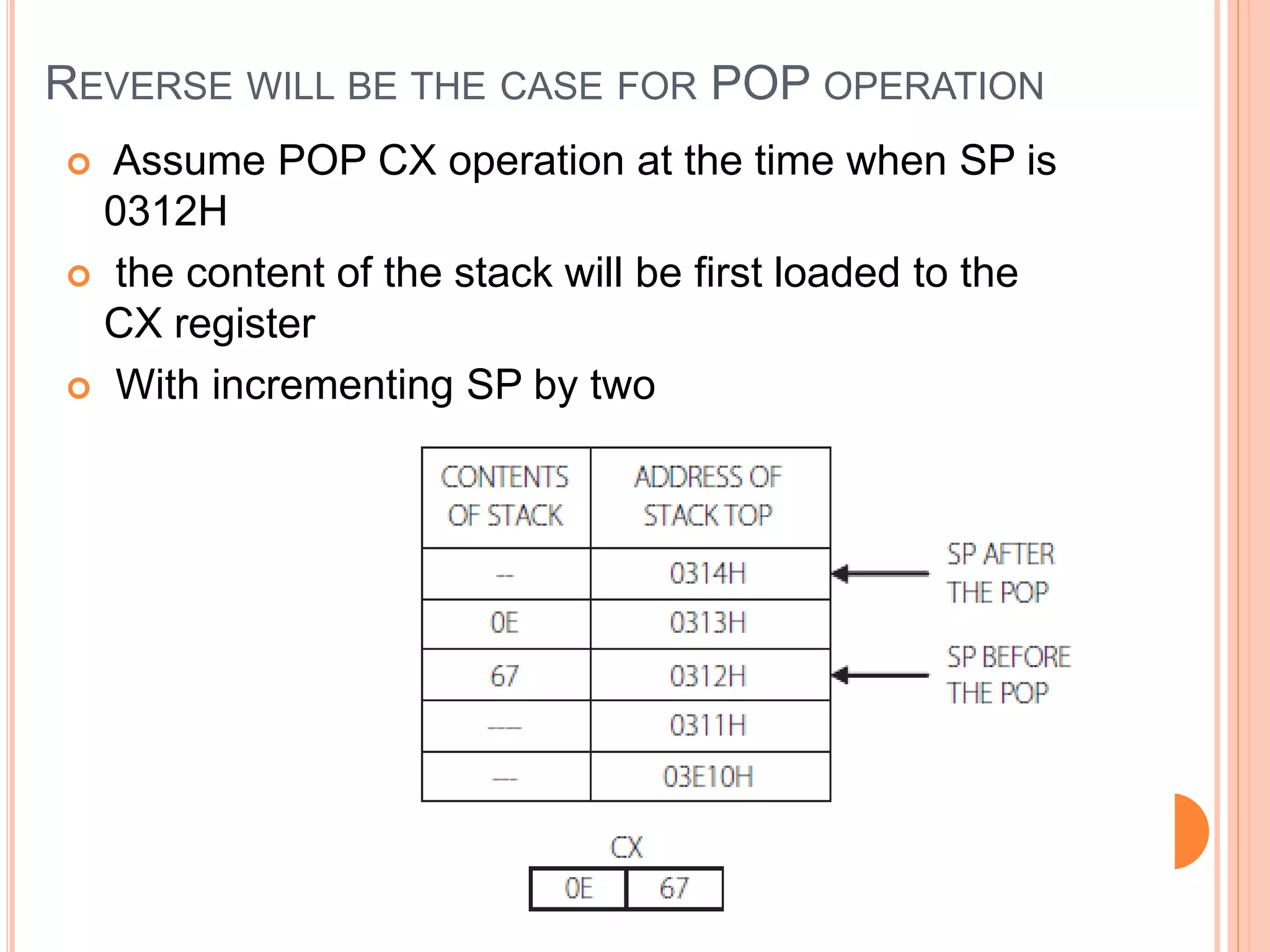
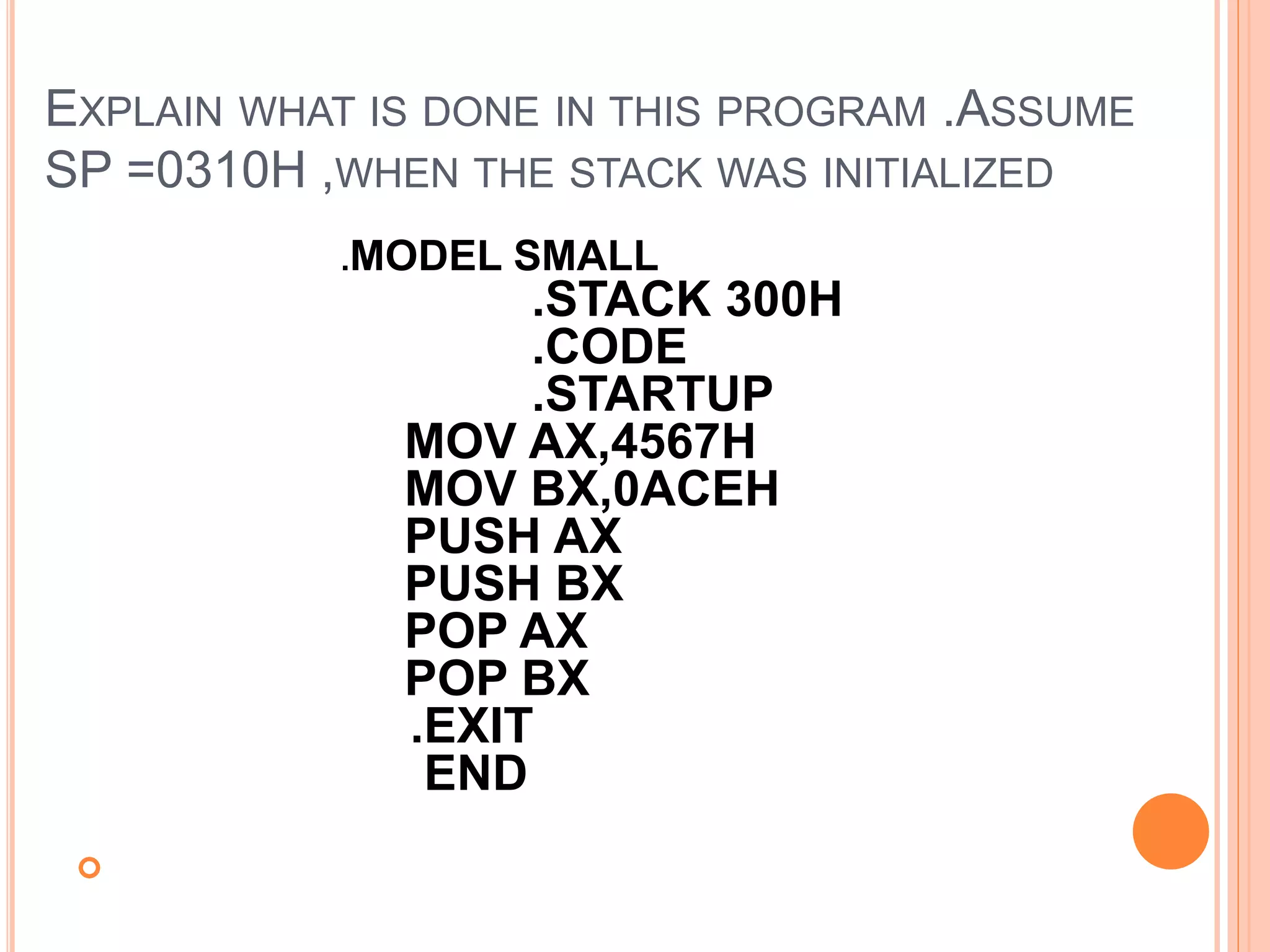
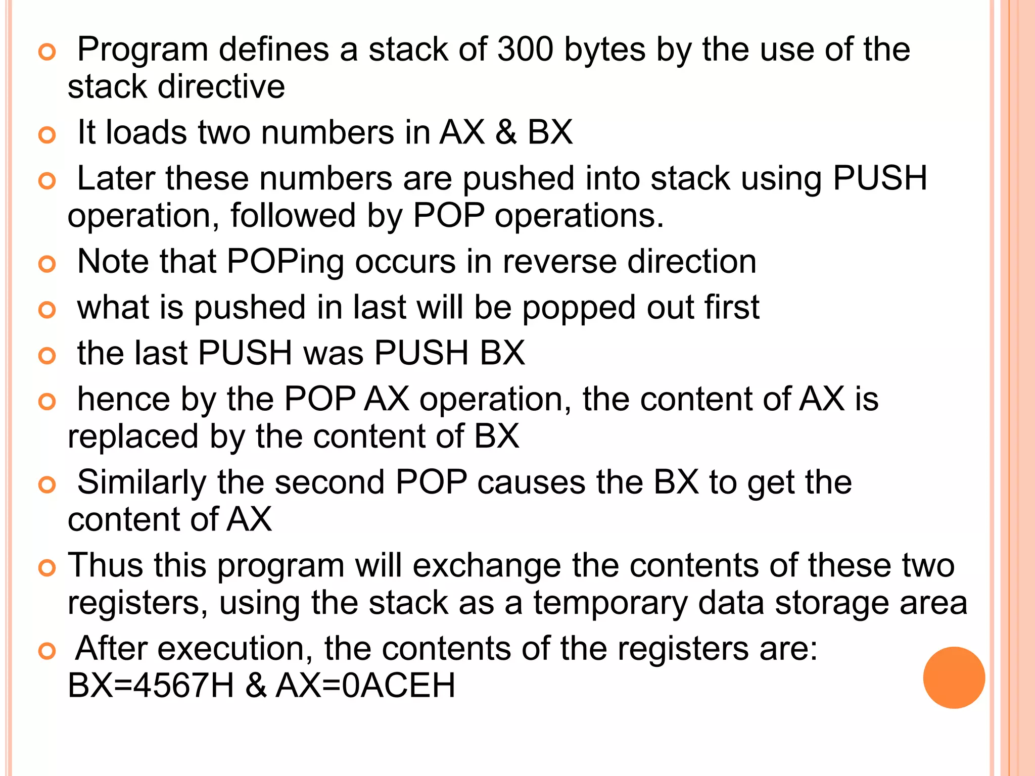
![PUSH AND POP Usage : PUSH source POP destination PUSH BX ; save the contents of BX to stack PUSH [BX ] ; save to stack the contents of the word pointed by BX PUSH DS ; save to stack the contents of the segment register DS PUSH COSTP ; save to stack the contents of the word location COSTP POP CX ; load the contents of the stack top to CX POP [SI] ; load the contents of the stack top to the memory location pointed by SI](https://image.slidesharecdn.com/chapter3-programmingconcepts-ii-170612053818/75/Chapter-3-programming-concepts-ii-32-2048.jpg)
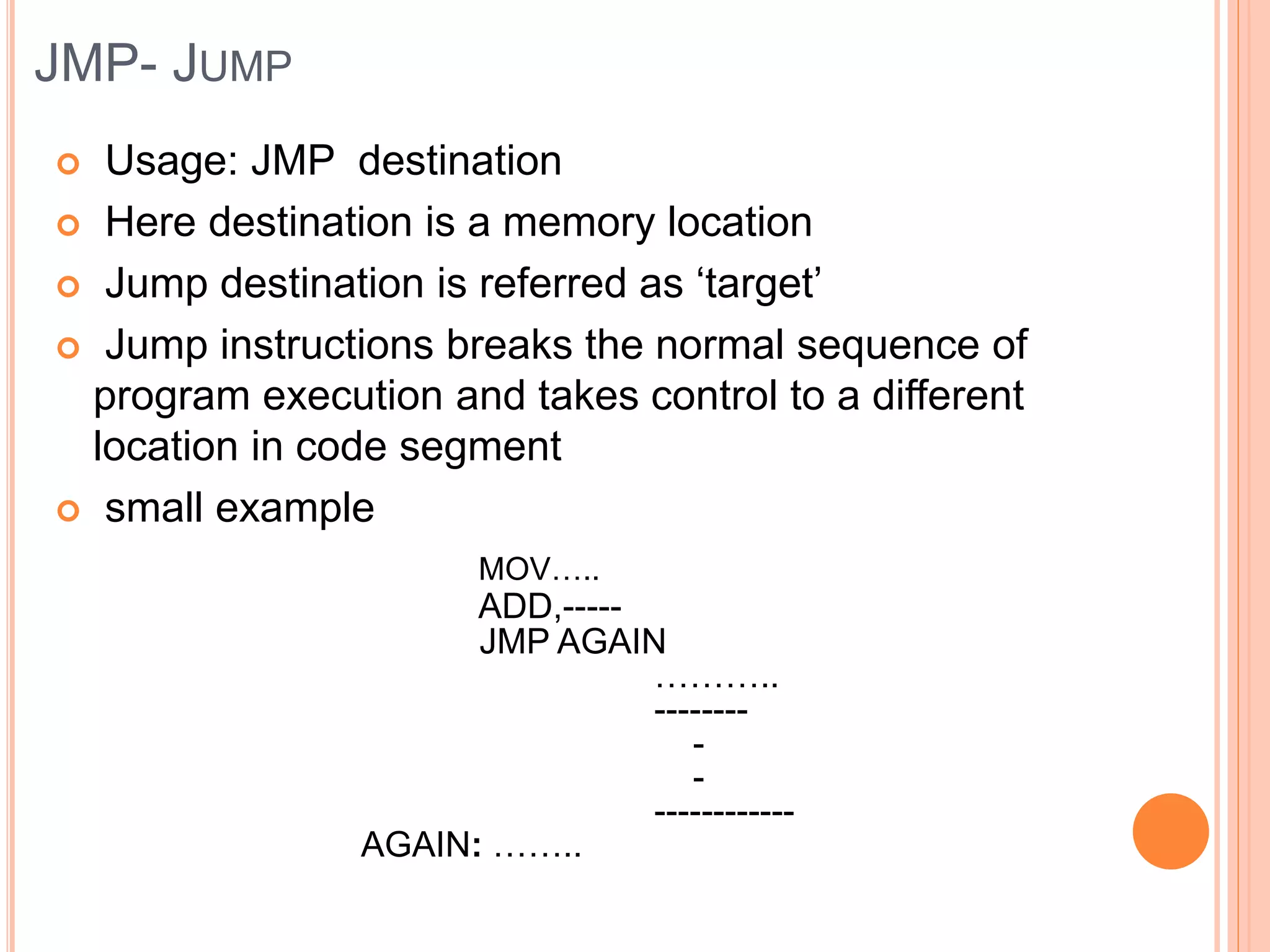
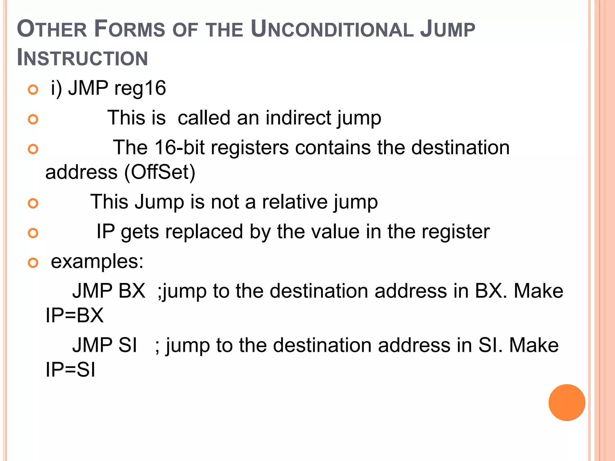
![ ii. JMP [reg 16] The register points to an address which contains the jump location e.g.JMP [SI] ; jump to the address which is stored in the memory location pointed by SI](https://image.slidesharecdn.com/chapter3-programmingconcepts-ii-170612053818/75/Chapter-3-programming-concepts-ii-44-2048.jpg)

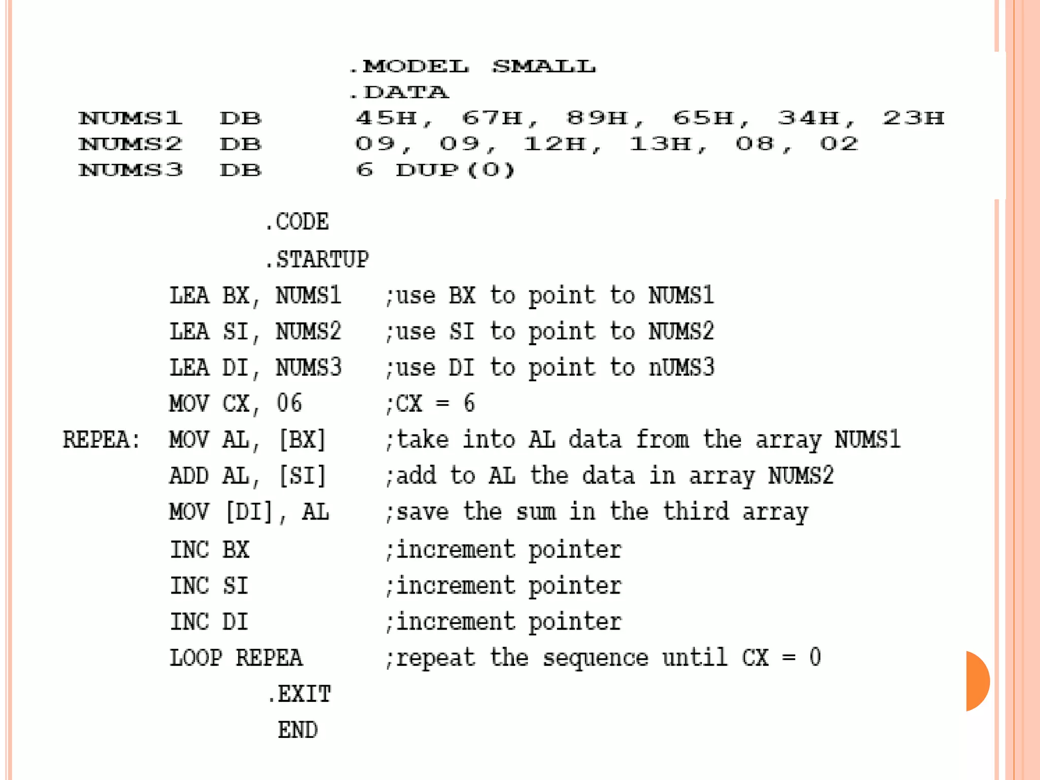

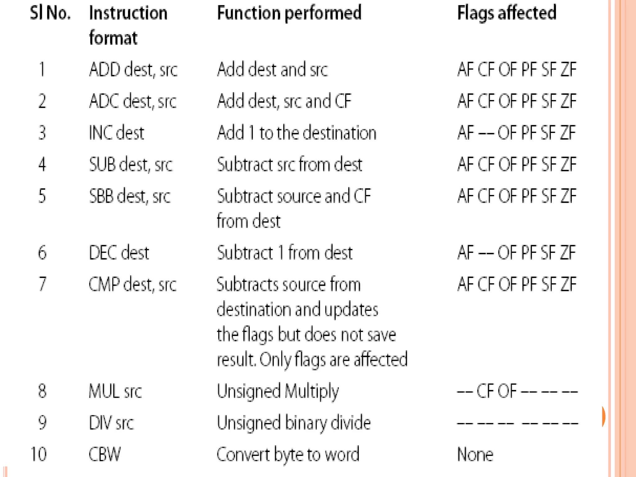
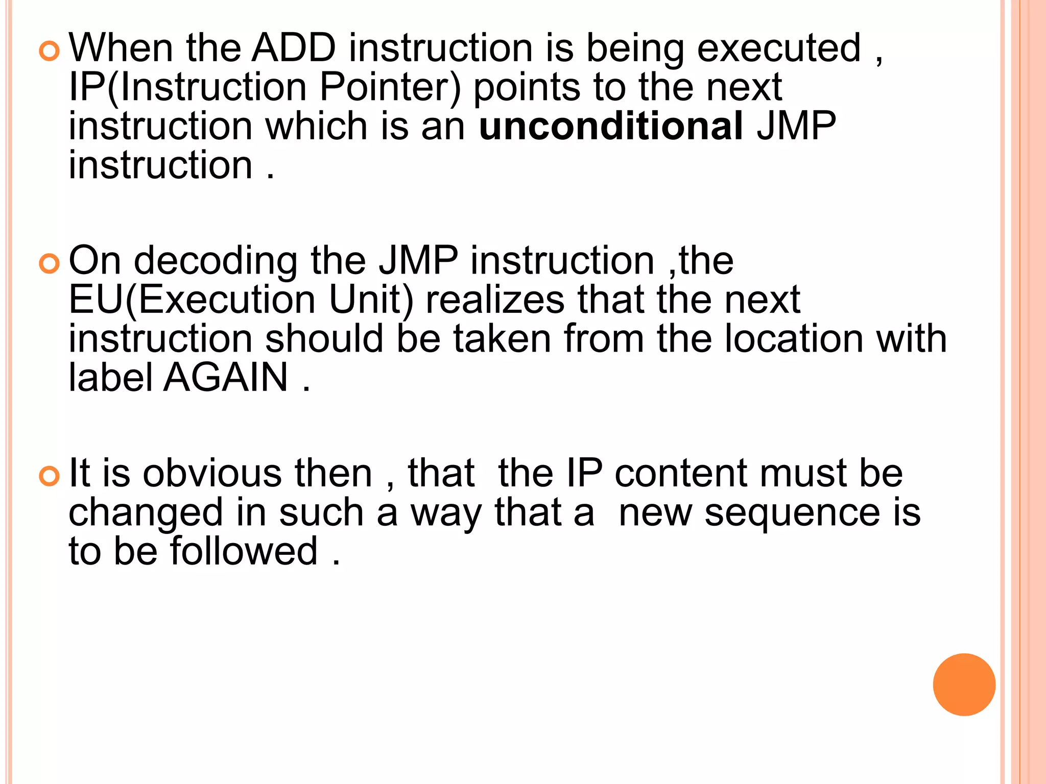
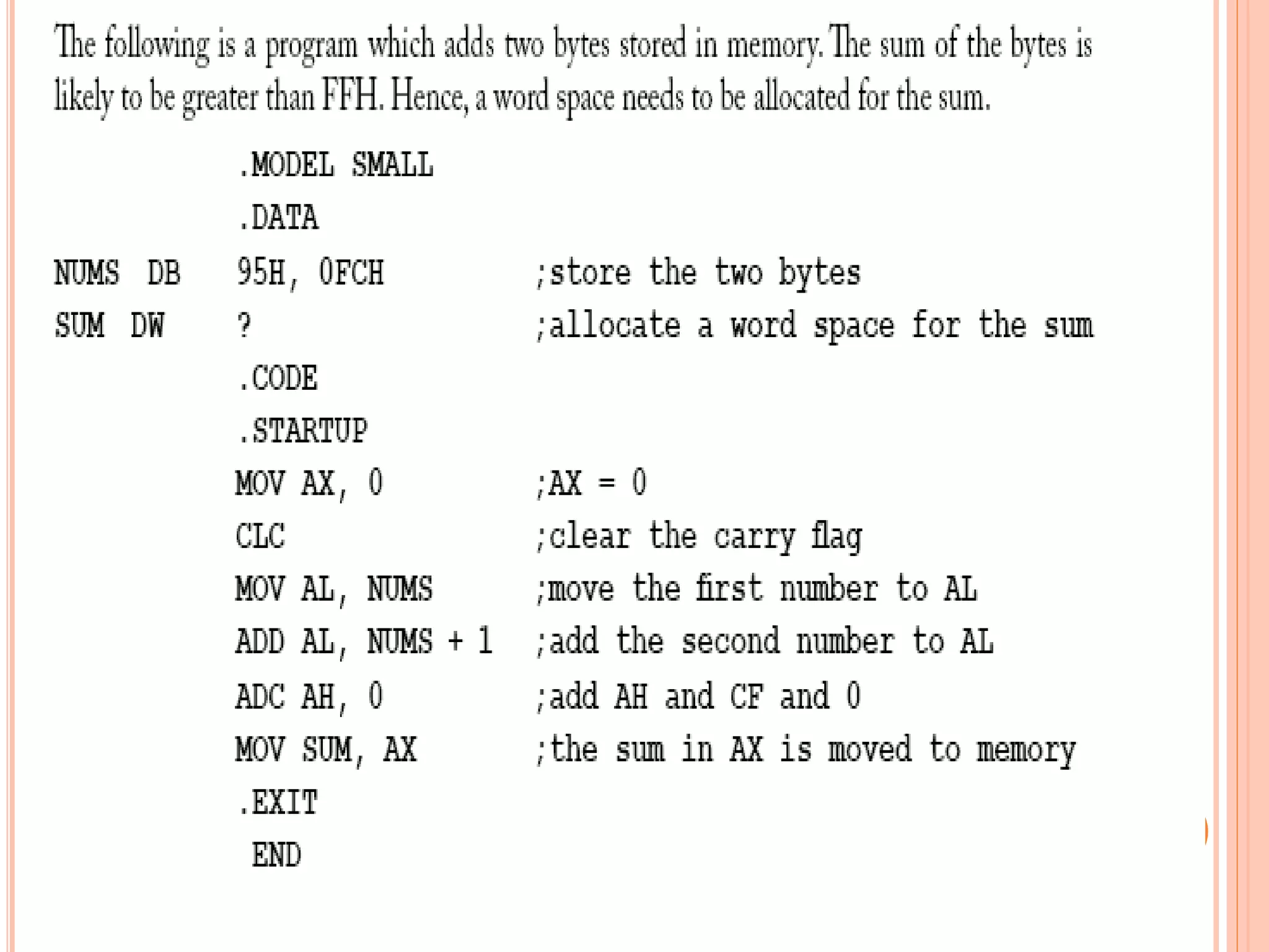
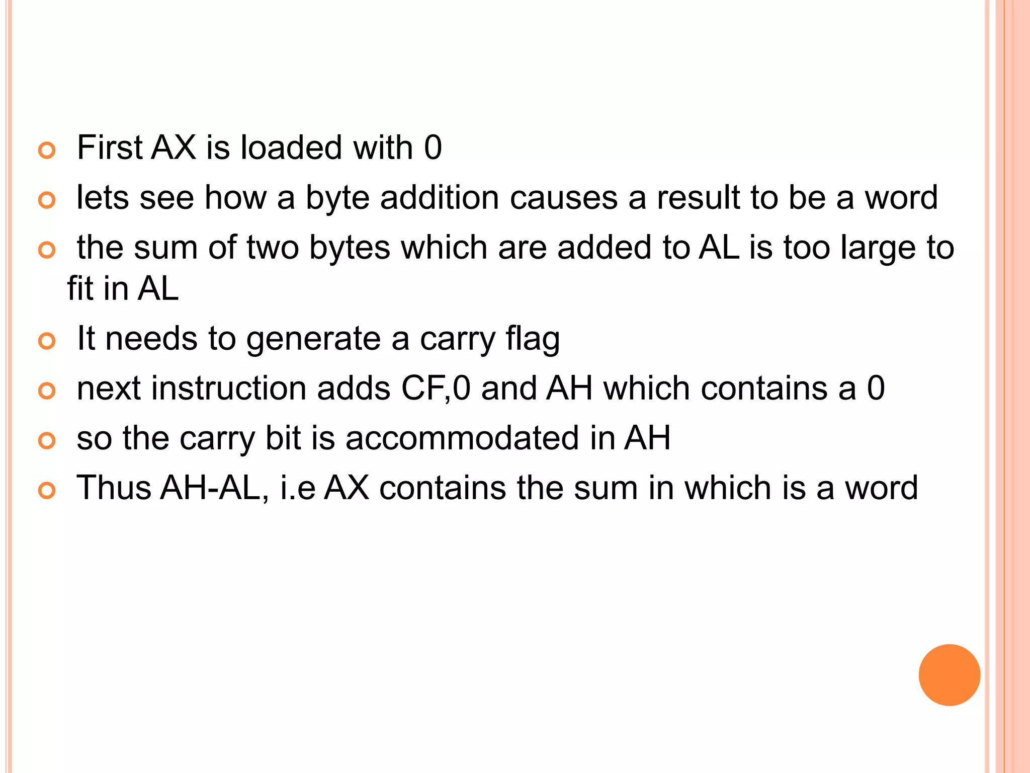
![ADDITION INSTRUCTIONS ADD – Add. Usage: ADD destination, source. This instruction adds the destination and source and puts the sum in the destination. All conditional flags get affected. Examples… ADD AH, AL ; add AL to AH, sum in AH ADD AL, COSTP ; add the byte in COSTP to AL, sum in AL ADD BX, 0987H ; add the number 987H to BX, sum in BX ADD CX, [BX] ; add the word in the location pointed by BX to CX sum in CX](https://image.slidesharecdn.com/chapter3-programmingconcepts-ii-170612053818/75/Chapter-3-programming-concepts-ii-57-2048.jpg)
![ ADC – Add with carry Usage: ADC destination, source This instruction adds CF and source to the destination, and puts the sum in the destination. There are three operands, of which the third is the carry. All conditional flags get affected. Examples…. ADC AH, 0 ; AH=AH+0+CF ADC [BX], AL ;add the byte pointed by BX with AL and CF, put sum in the location pointed by BX ADC AX, [BX][SI] ; add to AX, CF and the word with EA=BX+SI sum in AX](https://image.slidesharecdn.com/chapter3-programmingconcepts-ii-170612053818/75/Chapter-3-programming-concepts-ii-58-2048.jpg)
![ INC – Increment Usage: INC destination This instruction adds 1 to the destination. All conditional flags, except the carry flag, get affected. Examples… INC BX ; add 1 to the content of BX INC [BX] ; add 1 to the content of the m emory location pointed by BX INC AH ; add 1 to the content of AH](https://image.slidesharecdn.com/chapter3-programmingconcepts-ii-170612053818/75/Chapter-3-programming-concepts-ii-59-2048.jpg)
![PTR DIRECTIVE When the size of the operand is not implicit in the instruction, a pointer is used to indicate whether the operand is a byte, a word, or a double word. This is the PTR directive. Examples … INC BYTE PTR [BX] ;byte pointer or INC WORD PTR [BX] ;word pointer or INC DWORD PTR [BX] ;double word pointer](https://image.slidesharecdn.com/chapter3-programmingconcepts-ii-170612053818/75/Chapter-3-programming-concepts-ii-60-2048.jpg)
![SUBTRACTION SUB – Subtract. Usage: SUB destination, source. This instruction subtracts the source from the destination. The result is in the destination. All conditional flags are affected. Examples… SUB AX, BX ;subtract BX from AX SUB AL, [BX] ; Subtract the byte pointed by BX from AL SUB COST[SI], CX ; Subtract CX from the word with EA=COST+SI SUB AX, 8956H ;Subtract 8956H from AX SUB CL, BYTE PTR[SI] ; subtract from CL the byte pointed by SI](https://image.slidesharecdn.com/chapter3-programmingconcepts-ii-170612053818/75/Chapter-3-programming-concepts-ii-63-2048.jpg)
![SBB – SUBTRACT WITH BORROW Usage: SBB destination, source This instruction subtracts the source and the carry flag from the destination. All conditional flags are affected. • Examples… SBB CH, 7 ;subtract from CH, 7 and CF – result in CH SBB AX, [BP + 2] ; subtract from AX, the word pointed by [BP+2]. Since BP is used, the data is taken from the stack segment. The result in AX](https://image.slidesharecdn.com/chapter3-programmingconcepts-ii-170612053818/75/Chapter-3-programming-concepts-ii-64-2048.jpg)
![DEC – DECREMENT Usage: DEC destination. This instruction subtracts 1 from the destination. All conditional flags, except the carry flag, are affected. Examples.. DEC CL ;subtract 1 from CL DEC WORD PTR [SI] ; subtract 1 from the word pointed by SI DEC BYTE PTR NUMB[BX] ;subtract 1 from the byte pointed by the effective address NUMB+BX](https://image.slidesharecdn.com/chapter3-programmingconcepts-ii-170612053818/75/Chapter-3-programming-concepts-ii-65-2048.jpg)
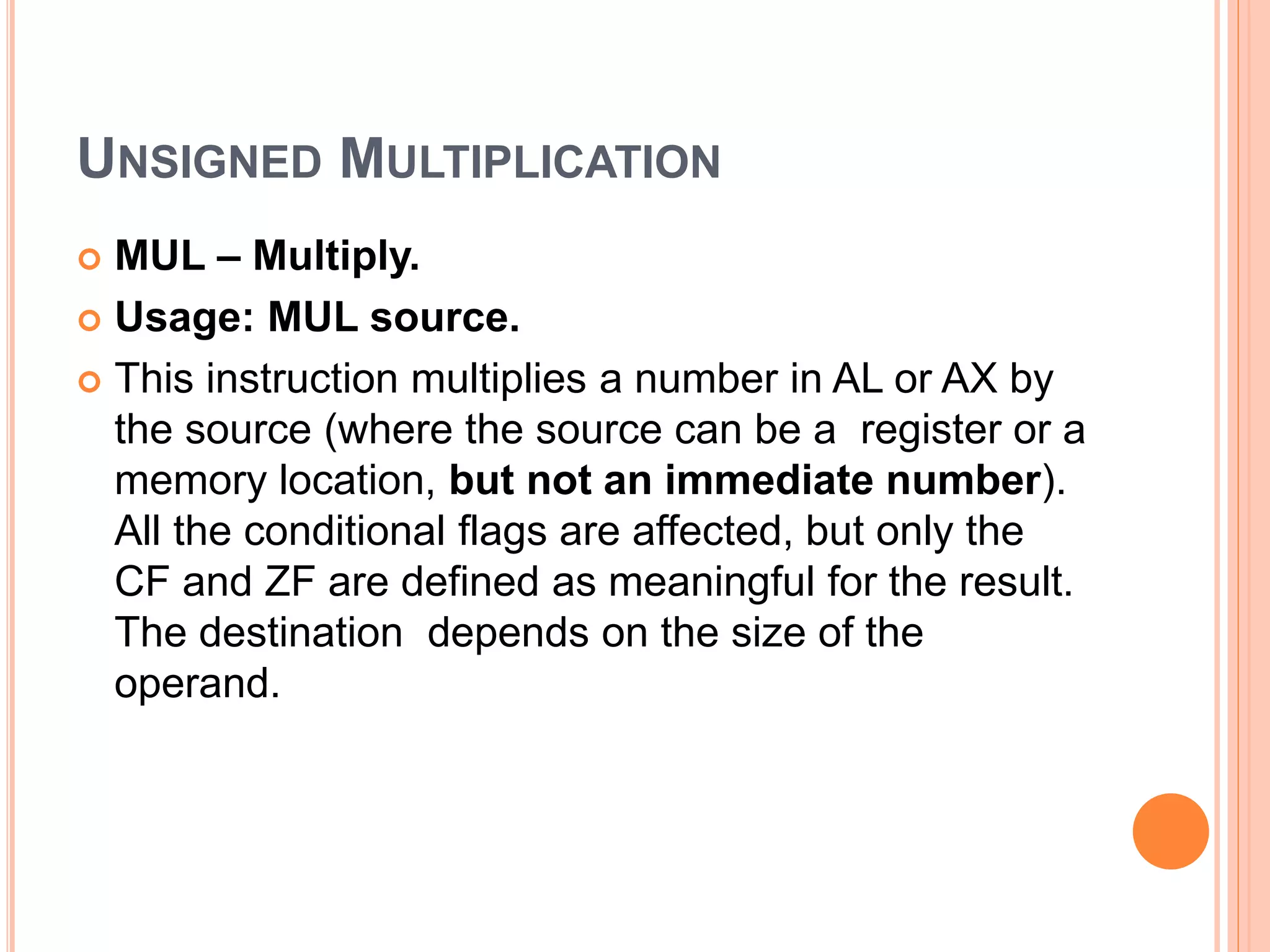
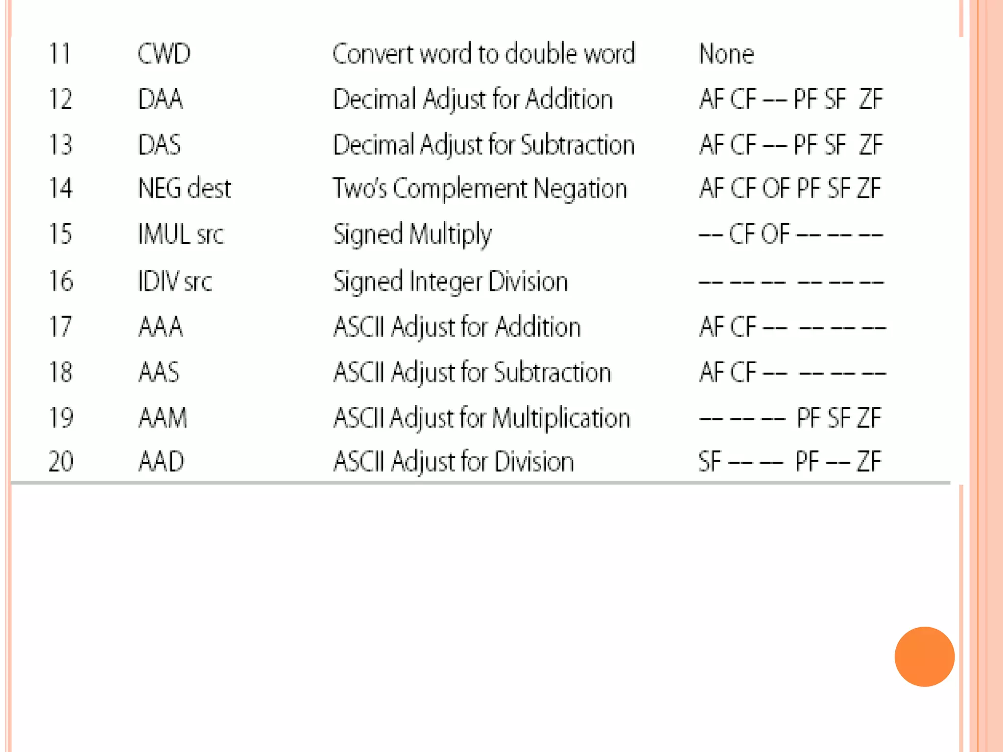
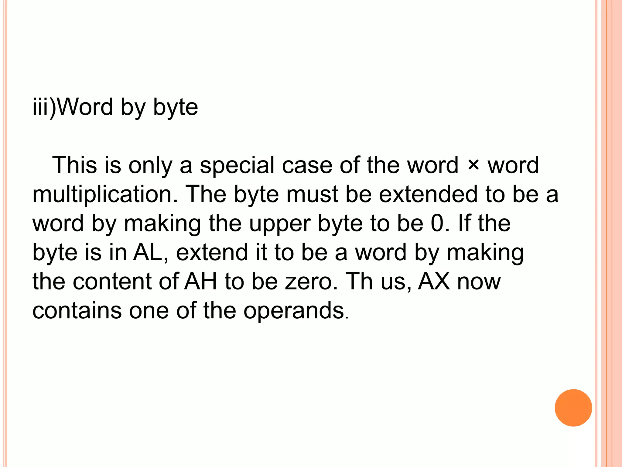
![Two ways of performing multiplication i) Byte by byte In this, one of the operands must be in the AL register, and the source can be a byte in a register or memory location. The product (a word) will be in AX. Examples …. MUL BL MUL BYTE PTR[SI] MUL BIG](https://image.slidesharecdn.com/chapter3-programmingconcepts-ii-170612053818/75/Chapter-3-programming-concepts-ii-67-2048.jpg)
![ii) Word by word In this, one of the operands must be in the AX register, and the source can be a word in a register or memory location. The product will be in DX and AX, with the upper word in DX. Examples… MUL CX MUL WORD PTR [DI]](https://image.slidesharecdn.com/chapter3-programmingconcepts-ii-170612053818/75/Chapter-3-programming-concepts-ii-68-2048.jpg)
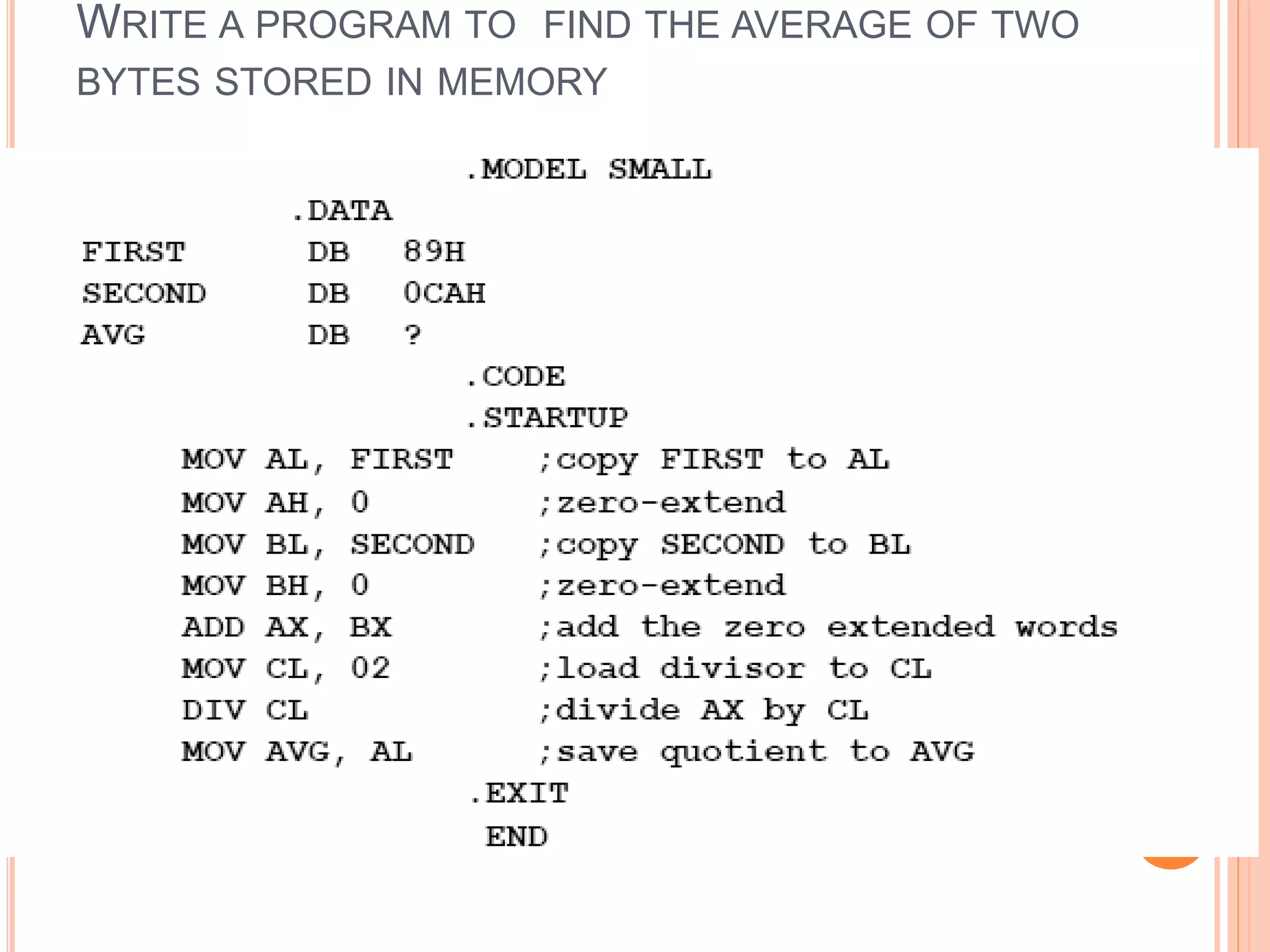
![WAYS OF PERFORMING DIVISION i. Divide a word by a byte Here, the dividend must be a word placed in AX and the source must be a byte. The result of division causes AL to contain the quotient, and AH to contain the remainder. Examples……… DIV BL DIV BYTE PTR [BX] DIV DIG](https://image.slidesharecdn.com/chapter3-programmingconcepts-ii-170612053818/75/Chapter-3-programming-concepts-ii-74-2048.jpg)
![iii. Divide a double word by a word. In this case, the dividend has to be in AX and DX (the upper word in DX). The divisor should be a word. The result of this division causes the quotient to be in AX and the remainder to be in DX. Examples… DIV BX DIV WORD PTR [SI] DIV ANGLE](https://image.slidesharecdn.com/chapter3-programmingconcepts-ii-170612053818/75/Chapter-3-programming-concepts-ii-76-2048.jpg)

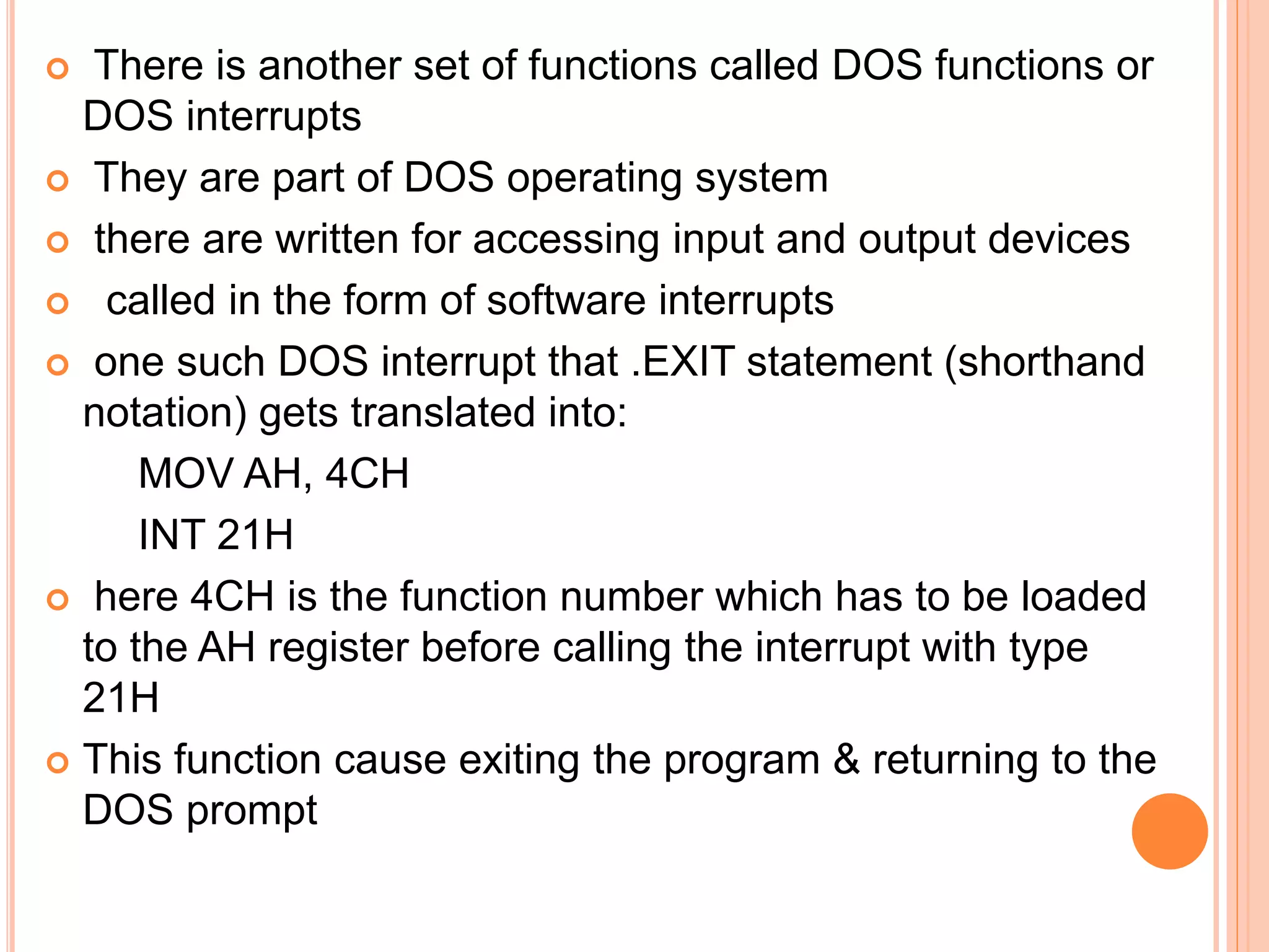
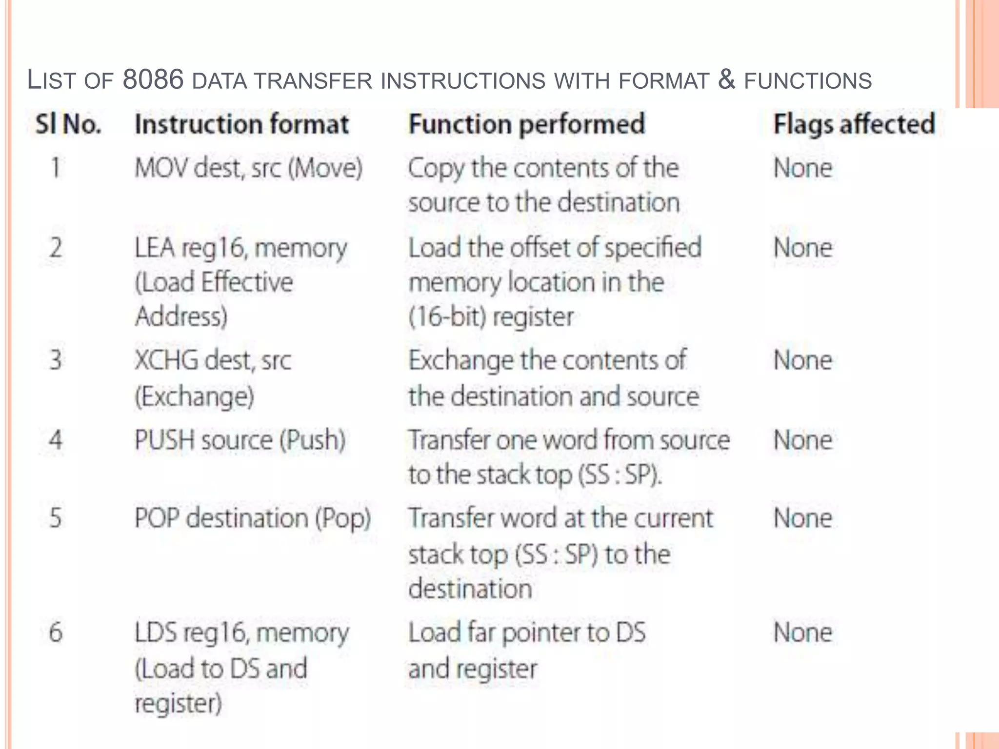
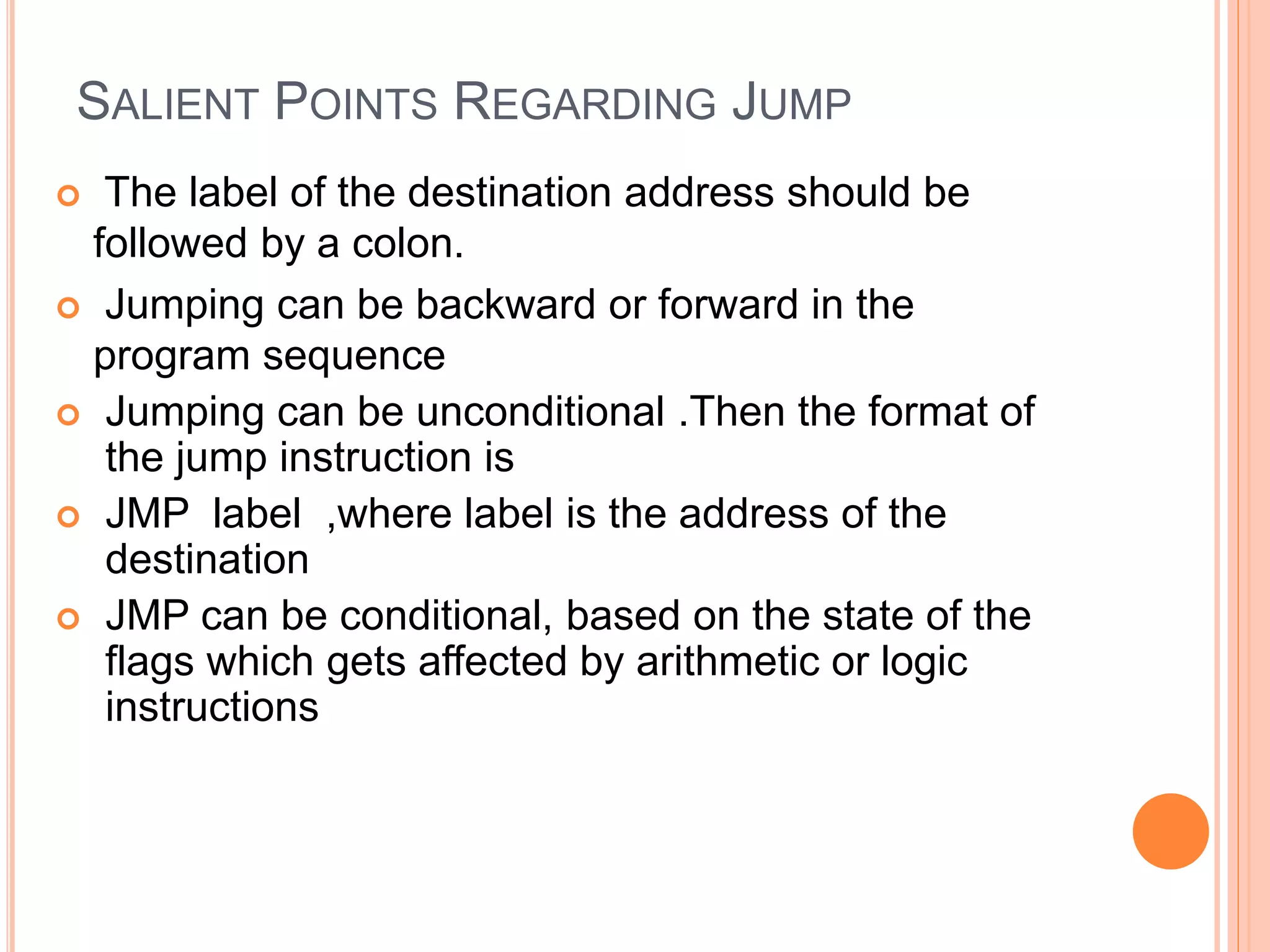
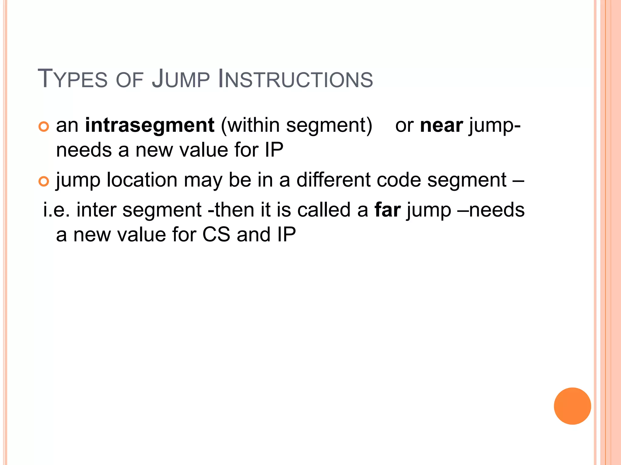
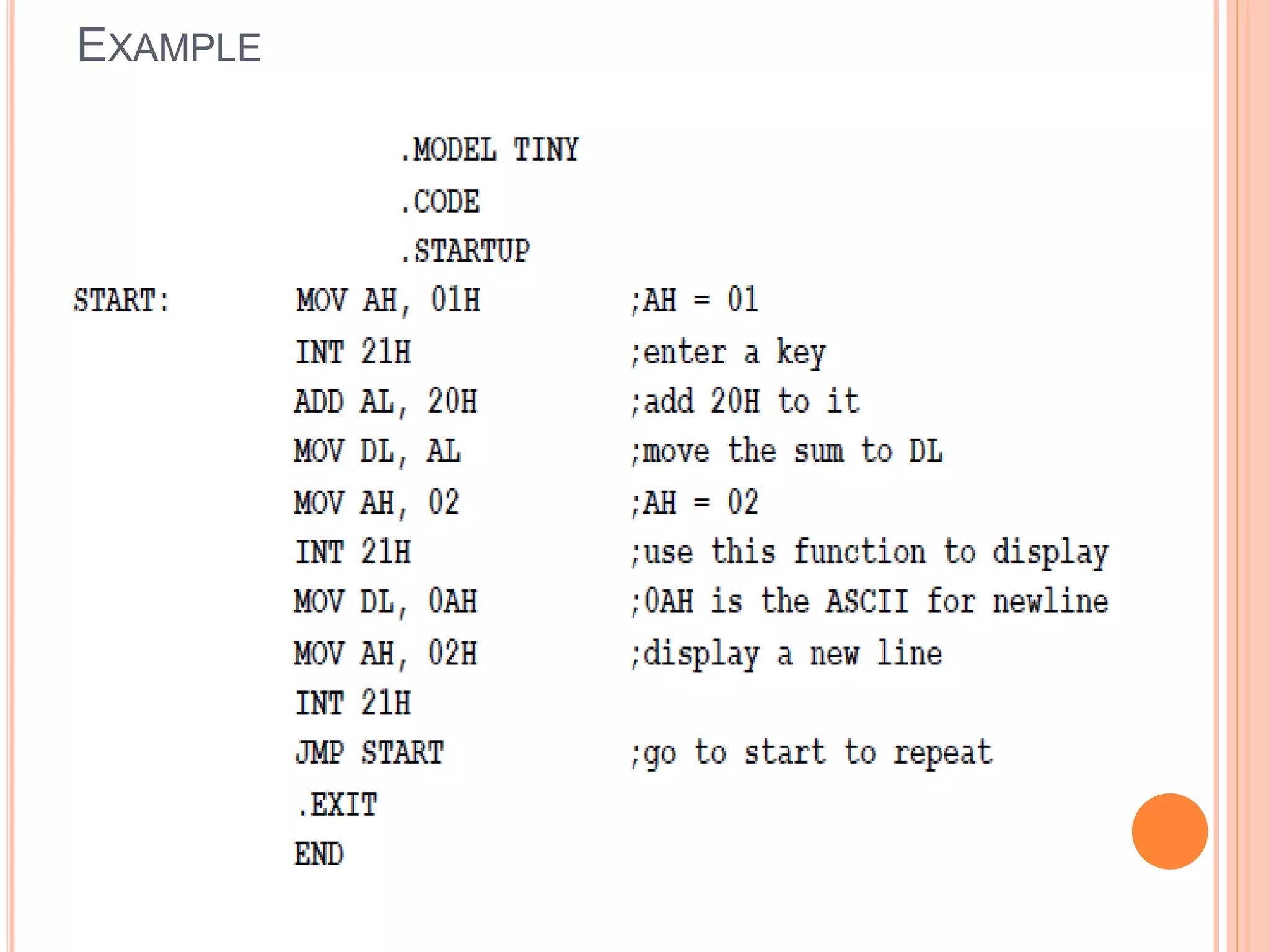
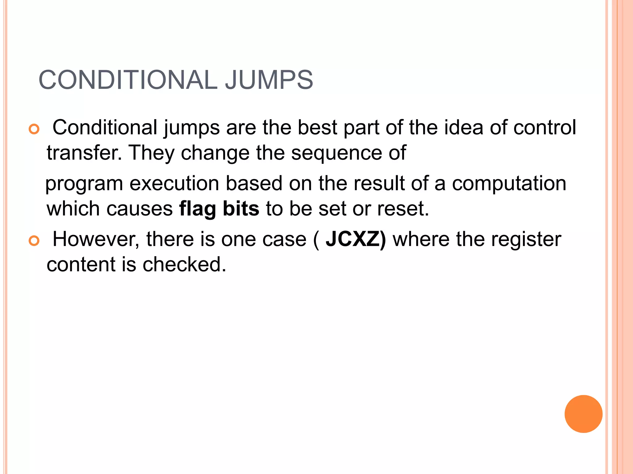
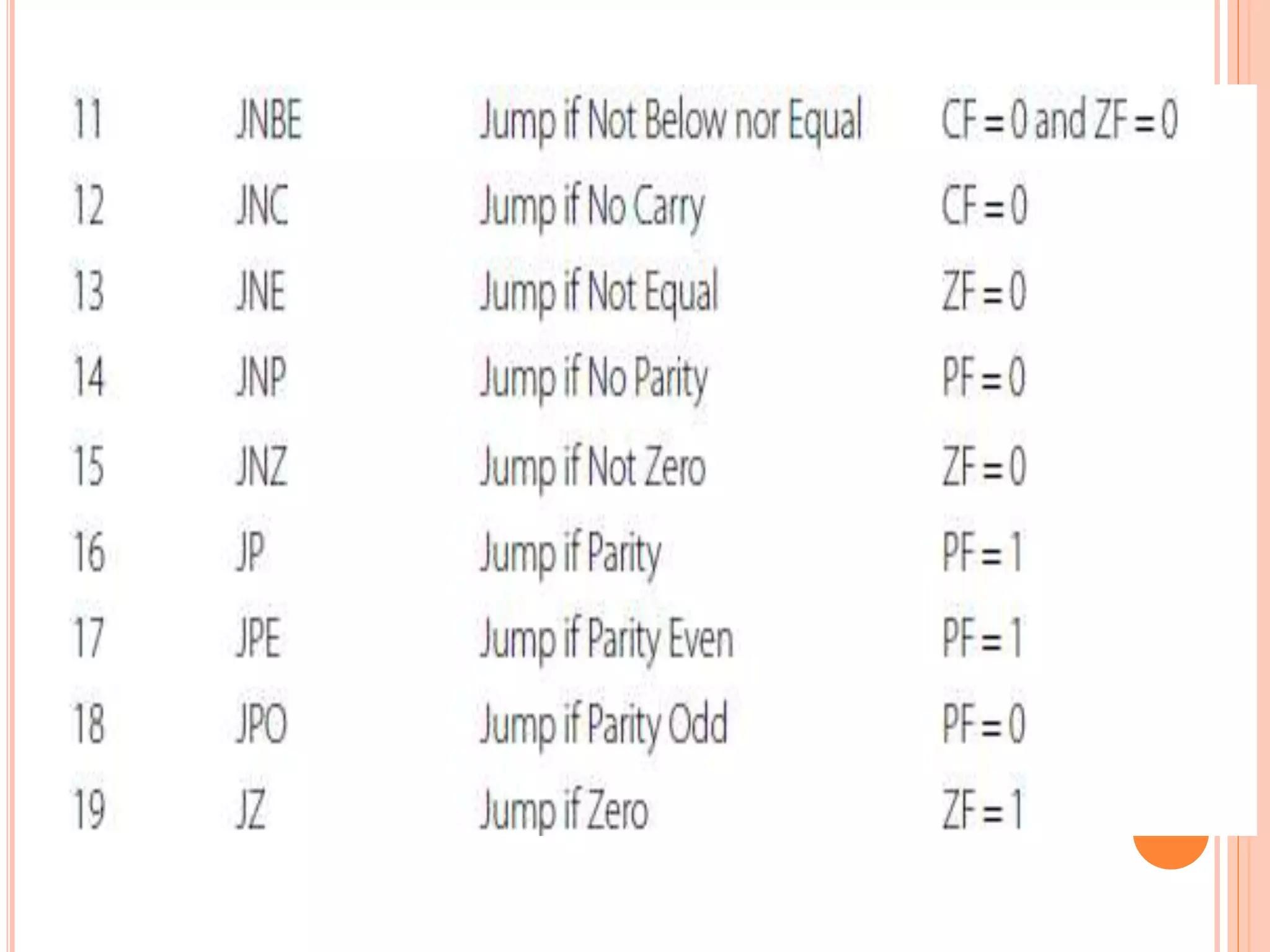
Chapter 3 discusses programming concepts, focusing on approaches to programming and the importance of mastering fundamentals. It covers the DOS operating system, how to handle input/output with BIOS and DOS functions, and the 8086 instruction set, including data transfer, stack operations, and branching instructions. Conditional and unconditional jumps, as well as arithmetic instructions, are also explained, alongside practical programming examples.