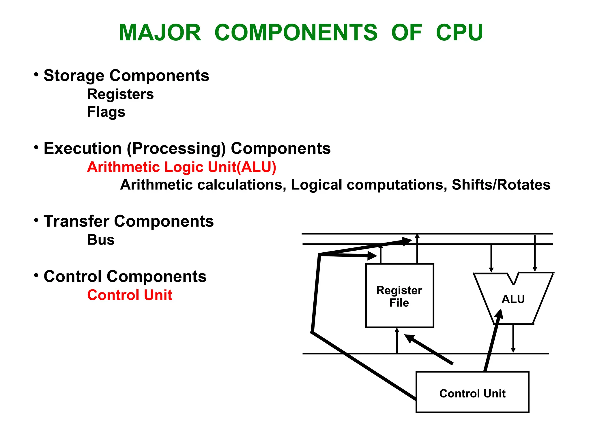
MAJOR COMPONENTS OFCPU • Storage Components Registers Flags • Execution (Processing) Components Arithmetic Logic Unit(ALU) Arithmetic calculations, Logical computations, Shifts/Rotates • Transfer Components Bus • Control Components Control Unit Register File ALU Control Unit
3.
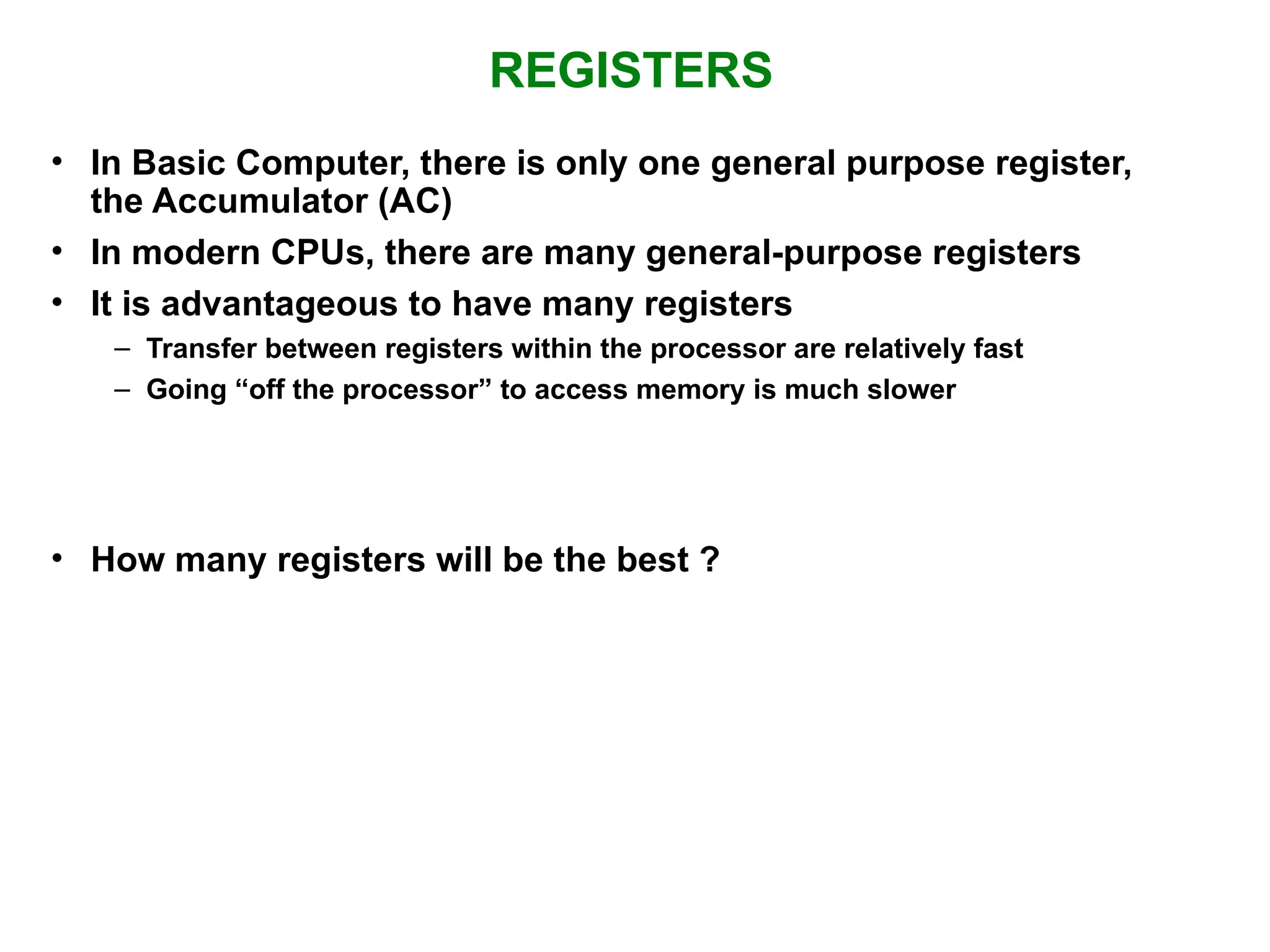
REGISTERS • In BasicComputer, there is only one general purpose register, the Accumulator (AC) • In modern CPUs, there are many general-purpose registers • It is advantageous to have many registers – Transfer between registers within the processor are relatively fast – Going “off the processor” to access memory is much slower • How many registers will be the best ?
4.
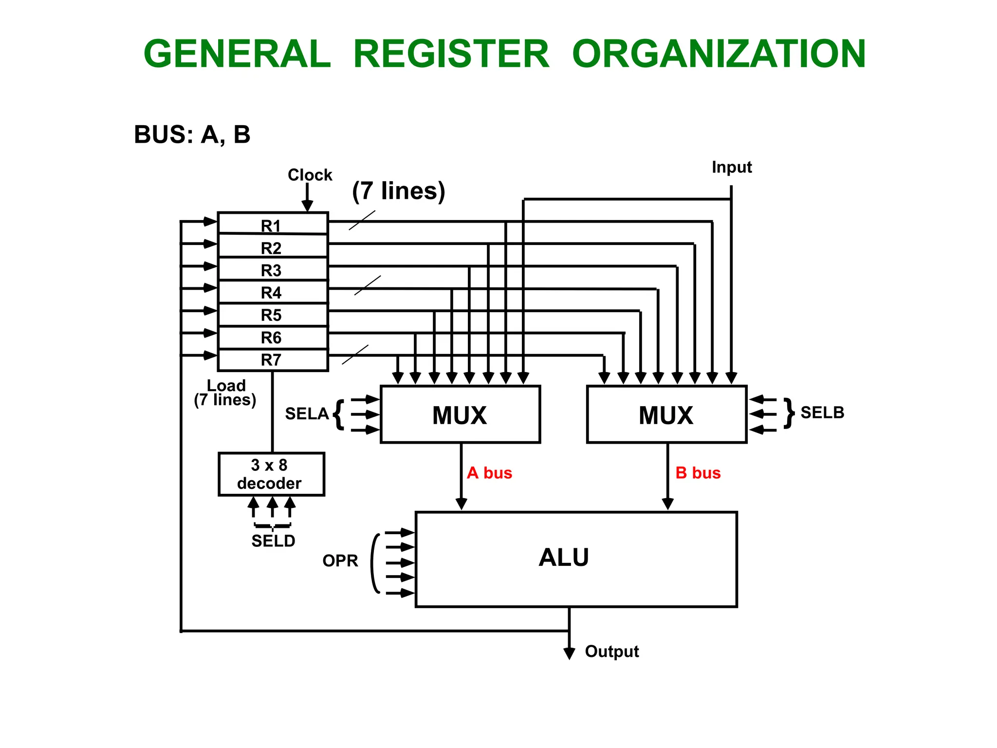
GENERAL REGISTER ORGANIZATION MUX SELA{ MUX }SELB ALU OPR R1 R2 R3 R4 R5 R6 R7 Input 3 x 8 decoder SELD Load (7 lines) Output A bus B bus Clock BUS: A, B (7 lines)
5.
OPERATION OF CONTROLUNIT The control unit Directs the information flow through ALU by - Selecting various Components in the system - Selecting the Function of ALU Example: R1 R2 + R3 [1] MUX A selector (SELA): BUS A R2 [2] MUX B selector (SELB): BUS B R3 [3] ALU operation selector (OPR): ALU to ADD [4] Decoder destination selector (SELD): R1 Out Bus Control Word Encoding of register selection fields Binary Code SELA SELB SELD 000 Input Input None 001 R1 R1 R1 010 R2 R2 R2 011 R3 R3 R3 100 R4 R4 R4 101 R5 R5 R5 110 R6 R6 R6 111 R7 R7 R7 SELA SELB SELD OPR 3 3 3 5
6.
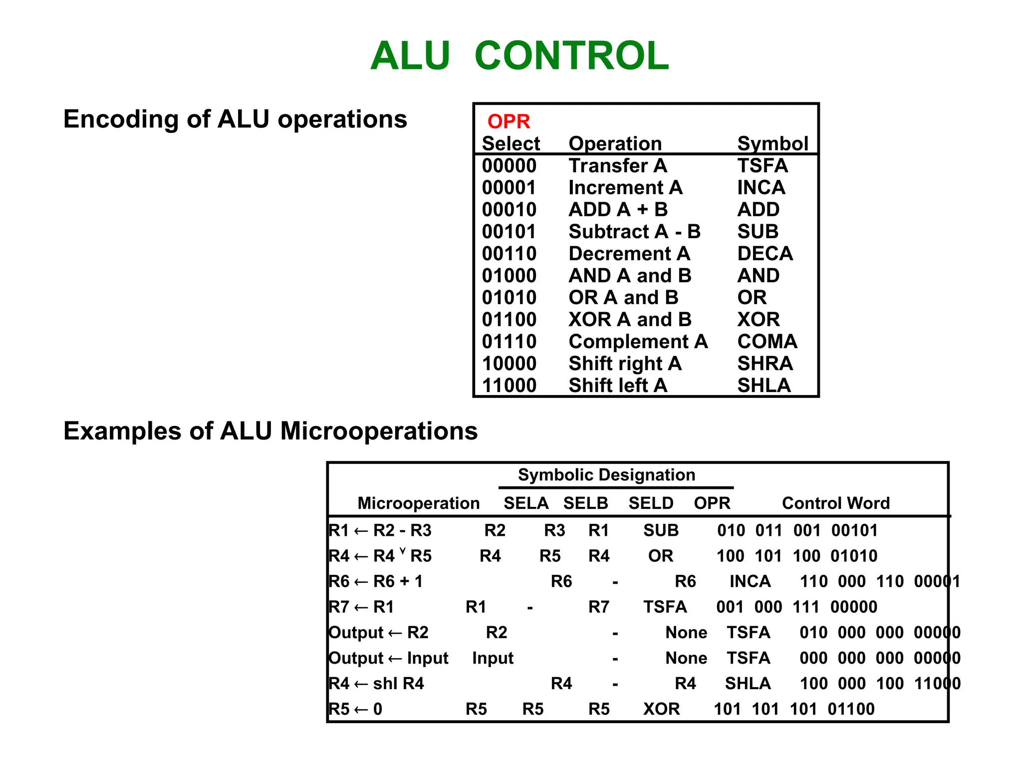
ALU CONTROL Encoding ofALU operations OPR Select Operation Symbol 00000 Transfer A TSFA 00001 Increment A INCA 00010 ADD A + B ADD 00101 Subtract A - B SUB 00110 Decrement A DECA 01000 AND A and B AND 01010 OR A and B OR 01100 XOR A and B XOR 01110 Complement A COMA 10000 Shift right A SHRA 11000 Shift left A SHLA Examples of ALU Microoperations Symbolic Designation Microoperation SELA SELB SELD OPR Control Word R1 R2 R3 R2 R3 R1 SUB 010 011 001 00101 R4 R4 R5 R4 R5 R4 OR 100 101 100 01010 R6 R6 + 1 R6 - R6 INCA 110 000 110 00001 R7 R1 R1 - R7 TSFA 001 000 111 00000 Output R2 R2 - None TSFA 010 000 000 00000 Output Input Input - None TSFA 000 000 000 00000 R4 shl R4 R4 - R4 SHLA 100 000 100 11000 R5 0 R5 R5 R5 XOR 101 101 101 01100
7.
REGISTER STACK ORGANIZATION RegisterStack Push, Pop operations /* Initially, SP = 0, EMPTY = 1, FULL = 0 */ PUSH POP SP SP + 1 DR M[SP] M[SP] DR SP SP 1 If (SP = 0) then (FULL 1) If (SP = 0) then (EMPTY 1) EMPTY 0 FULL 0 Stack - Very useful feature for nested subroutines, nested interrupt services - Also efficient for arithmetic expression evaluation - Storage which can be accessed in LIFO - Pointer: SP - Only PUSH and POP operations are applicable A B C 0 1 2 3 4 63 Address FULL EMPTY SP DR Flags Stack pointer stack 6 bits
8.
MEMORY STACK ORGANIZATION -A portion of memory is used as a stack with a processor register as a stack pointer - PUSH: SP SP - 1 M[SP] DR - POP: DR M[SP] SP SP + 1 Memory with Program, Data, and Stack Segments 4001 4000 3999 3998 3997 3000 Data (operands) Program (instructions) 1000 PC AR SP stack Stack grows In this direction - Most computers do not provide hardware to check stack overflow (full stack) or underflow (empty stack) must be done in software
9.
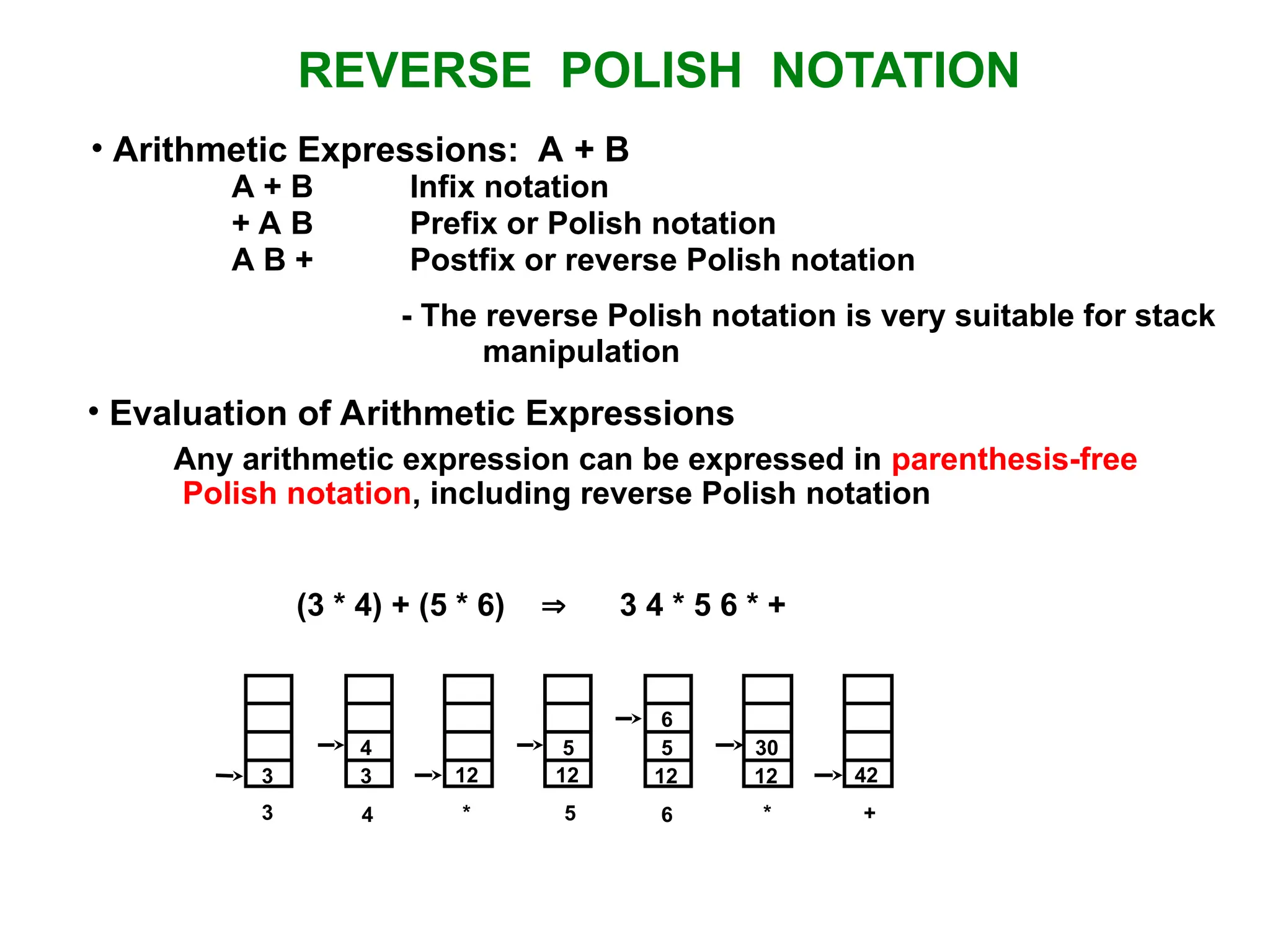
REVERSE POLISH NOTATION A+ B Infix notation + A B Prefix or Polish notation A B + Postfix or reverse Polish notation - The reverse Polish notation is very suitable for stack manipulation • Evaluation of Arithmetic Expressions Any arithmetic expression can be expressed in parenthesis-free Polish notation, including reverse Polish notation (3 * 4) + (5 * 6) 3 4 * 5 6 * + • Arithmetic Expressions: A + B 3 3 12 12 12 12 42 4 5 5 6 30 3 4 * 5 6 * +
10.
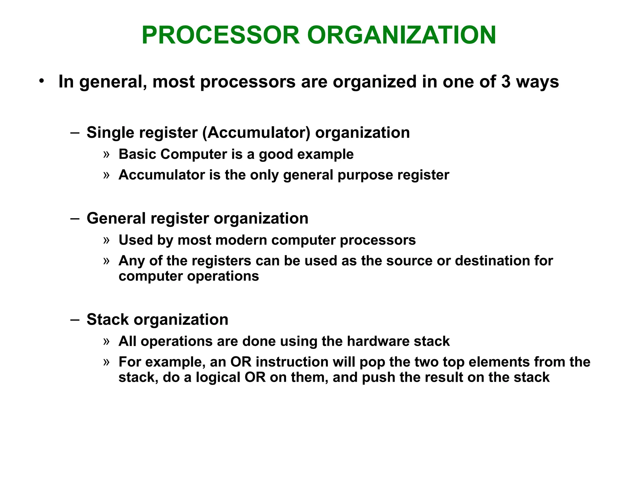
PROCESSOR ORGANIZATION • Ingeneral, most processors are organized in one of 3 ways – Single register (Accumulator) organization » Basic Computer is a good example » Accumulator is the only general purpose register – General register organization » Used by most modern computer processors » Any of the registers can be used as the source or destination for computer operations – Stack organization » All operations are done using the hardware stack » For example, an OR instruction will pop the two top elements from the stack, do a logical OR on them, and push the result on the stack
11.
INSTRUCTION FORMAT OP-code field- specifies the operation to be performed Address field - designates memory address(es) or a processor register(s) Mode field - determines how the address field is to be interpreted (to get effective address or the operand) • The number of address fields in the instruction format depends on the internal organization of CPU • The three most common CPU organizations: Single accumulator organization: ADD X /* AC AC + M[X] */ General register organization: ADD R1, R2, R3 /* R1 R2 + R3 */ ADD R1, R2 /* R1 R1 + R2 */ MOV R1, R2 /* R1 R2 */ ADD R1, X /* R1 R1 + M[X] */ Stack organization: PUSH X /* TOS M[X] */ ADD • Instruction Fields
12.
• Three-Address Instructions Programto evaluate X = (A + B) * (C + D) : ADD R1, A, B /* R1 M[A] + M[B] */ ADD R2, C, D /* R2 M[C] + M[D] */ MUL X, R1, R2 /* M[X] R1 * R2 */ - Results in short programs (Advantage) - Instruction becomes long (many bits) • Two-Address Instructions Program to evaluate X = (A + B) * (C + D) : MOV R1, A /* R1 M[A] */ ADD R1, B /* R1 R1 + M[A] */ MOV R2, C /* R2 M[C] */ ADD R2, D /* R2 R2 + M[D] */ MUL R1, R2 /* R1 R1 * R2 */ MOV X, R1 /* M[X] R1 */ THREE, AND TWO-ADDRESS INSTRUCTIONS
13.
ONE, AND ZERO-ADDRESSINSTRUCTIONS • One-Address Instructions - Use an implied AC register for all data manipulation - Program to evaluate X = (A + B) * (C + D) : LOAD A /* AC M[A] */ ADD B /* AC AC + M[B] */ STORE T /* M[T] AC */ LOAD C /* AC M[C] */ ADD D /* AC AC + M[D] */ MUL T /* AC AC * M[T] */ STORE X /* M[X] AC */ • Zero-Address Instructions - Can be found in a stack-organized computer - Program to evaluate X = (A + B) * (C + D) : PUSH A /* TOS A */ PUSH B /* TOS B */ ADD /* TOS (A + B) */ PUSH C /* TOS C */ PUSH D /* TOS D */ ADD /* TOS (C + D) */ MUL /* TOS (C + D) * (A + B) */ POP X /* M[X] TOS */
14.
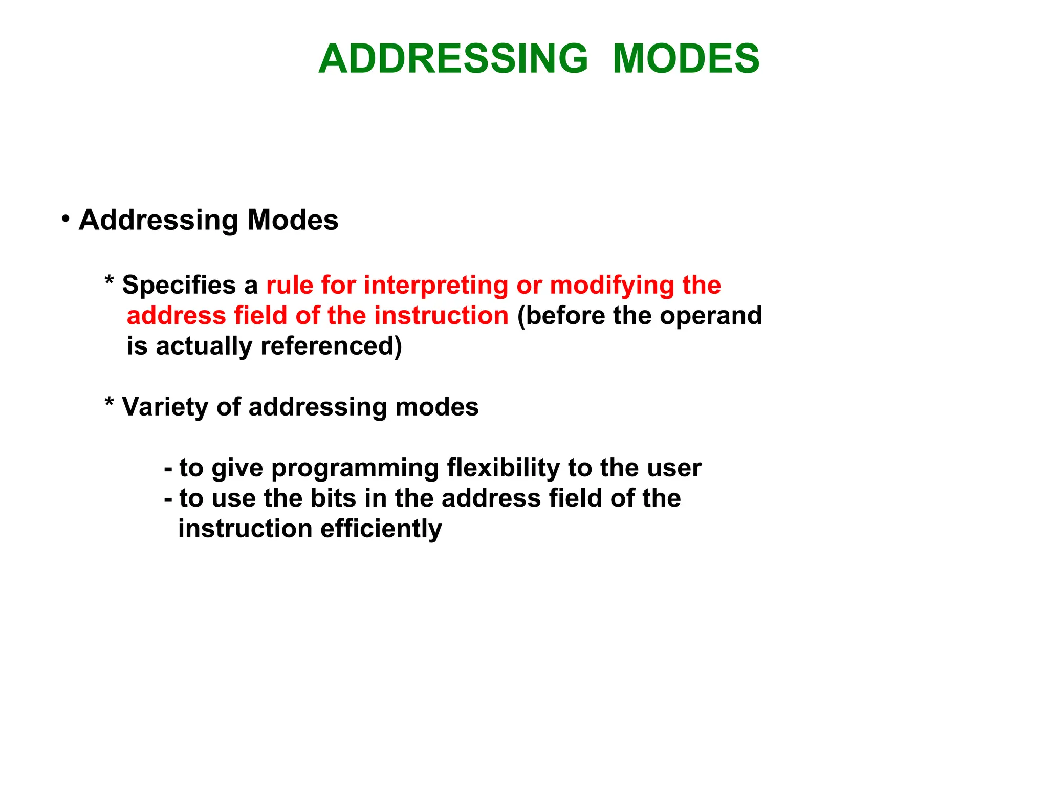
ADDRESSING MODES • AddressingModes * Specifies a rule for interpreting or modifying the address field of the instruction (before the operand is actually referenced) * Variety of addressing modes - to give programming flexibility to the user - to use the bits in the address field of the instruction efficiently
15.
TYPES OF ADDRESSINGMODES • Implied Mode Address of the operands are specified implicitly in the definition of the instruction - No need to specify address in the instruction - EA = AC, or EA = Stack[SP] - Examples from Basic Computer CLA, CME, INP • Immediate Mode Instead of specifying the address of the operand, operand itself is specified - No need to specify address in the instruction - However, operand itself needs to be specified - Sometimes, require more bits than the address - Fast to acquire an operand
16.
TYPES OF ADDRESSINGMODES • Register Mode Address specified in the instruction is the register address - Designated operand need to be in a register - Shorter address than the memory address - Saving address field in the instruction - Faster to acquire an operand than the memory addressing - EA = IR(R) (IR(R): Register field of IR) • Register Indirect Mode Instruction specifies a register which contains the memory address of the operand - Saving instruction bits since register address is shorter than the memory address - Slower to acquire an operand than both the register addressing or memory addressing - EA = [IR(R)] ([x]: Content of x) • Autoincrement or Autodecrement Mode - When the address in the register is used to access memory, the value in the register is incremented or decremented by 1 automatically
17.
TYPES OF ADDRESSINGMODES • Direct Address Mode Instruction specifies the memory address which can be used directly to access the memory - Faster than the other memory addressing modes - Too many bits are needed to specify the address for a large physical memory space - EA = IR(addr) (IR(addr): address field of IR) • Indirect Addressing Mode The address field of an instruction specifies the address of a memory location that contains the address of the operand - When the abbreviated address is used large physical memory can be addressed with a relatively small number of bits - Slow to acquire an operand because of an additional memory access - EA = M[IR(address)]
18.
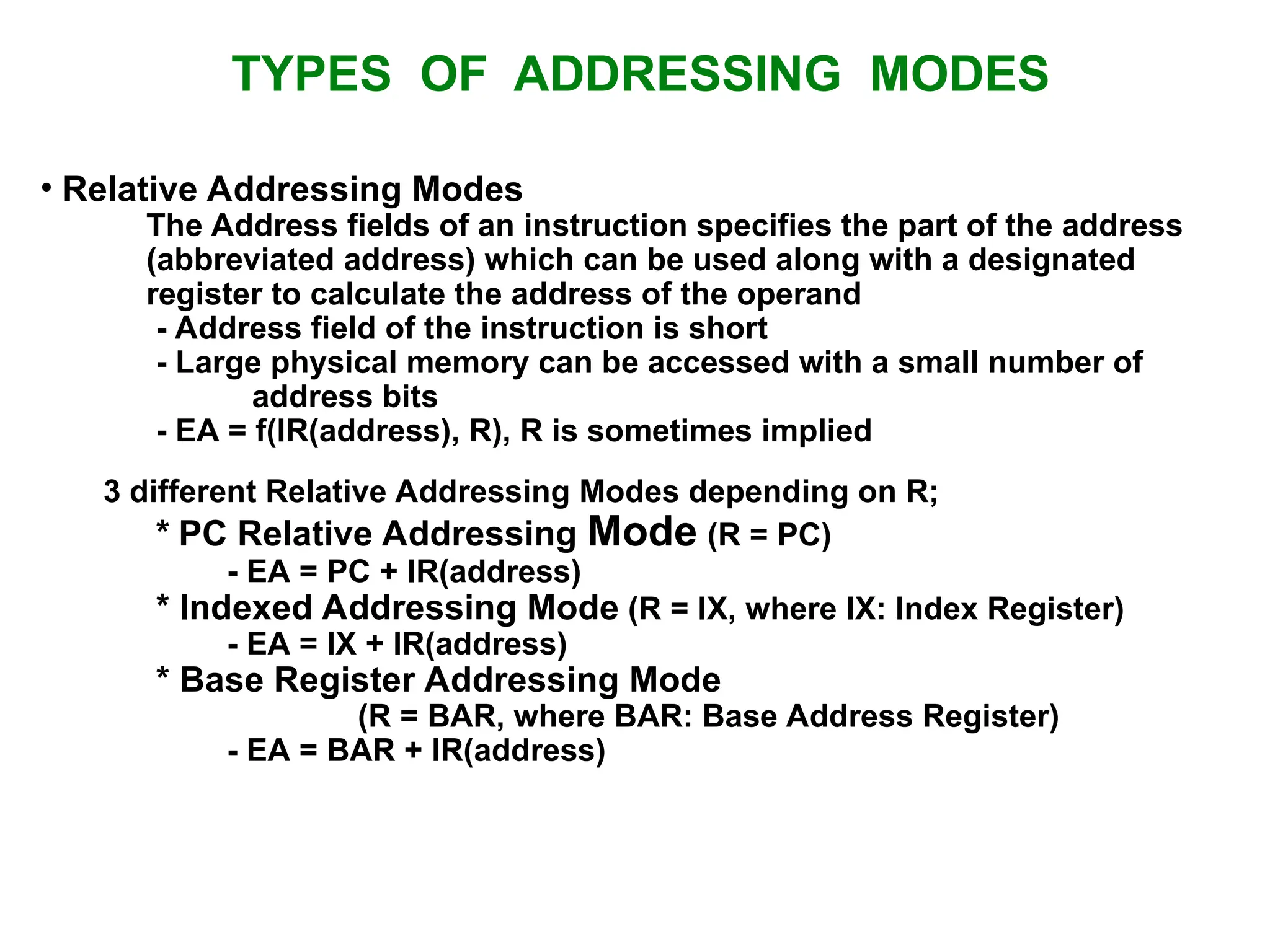
TYPES OF ADDRESSINGMODES • Relative Addressing Modes The Address fields of an instruction specifies the part of the address (abbreviated address) which can be used along with a designated register to calculate the address of the operand - Address field of the instruction is short - Large physical memory can be accessed with a small number of address bits - EA = f(IR(address), R), R is sometimes implied 3 different Relative Addressing Modes depending on R; * PC Relative Addressing Mode (R = PC) - EA = PC + IR(address) * Indexed Addressing Mode (R = IX, where IX: Index Register) - EA = IX + IR(address) * Base Register Addressing Mode (R = BAR, where BAR: Base Address Register) - EA = BAR + IR(address)
19.
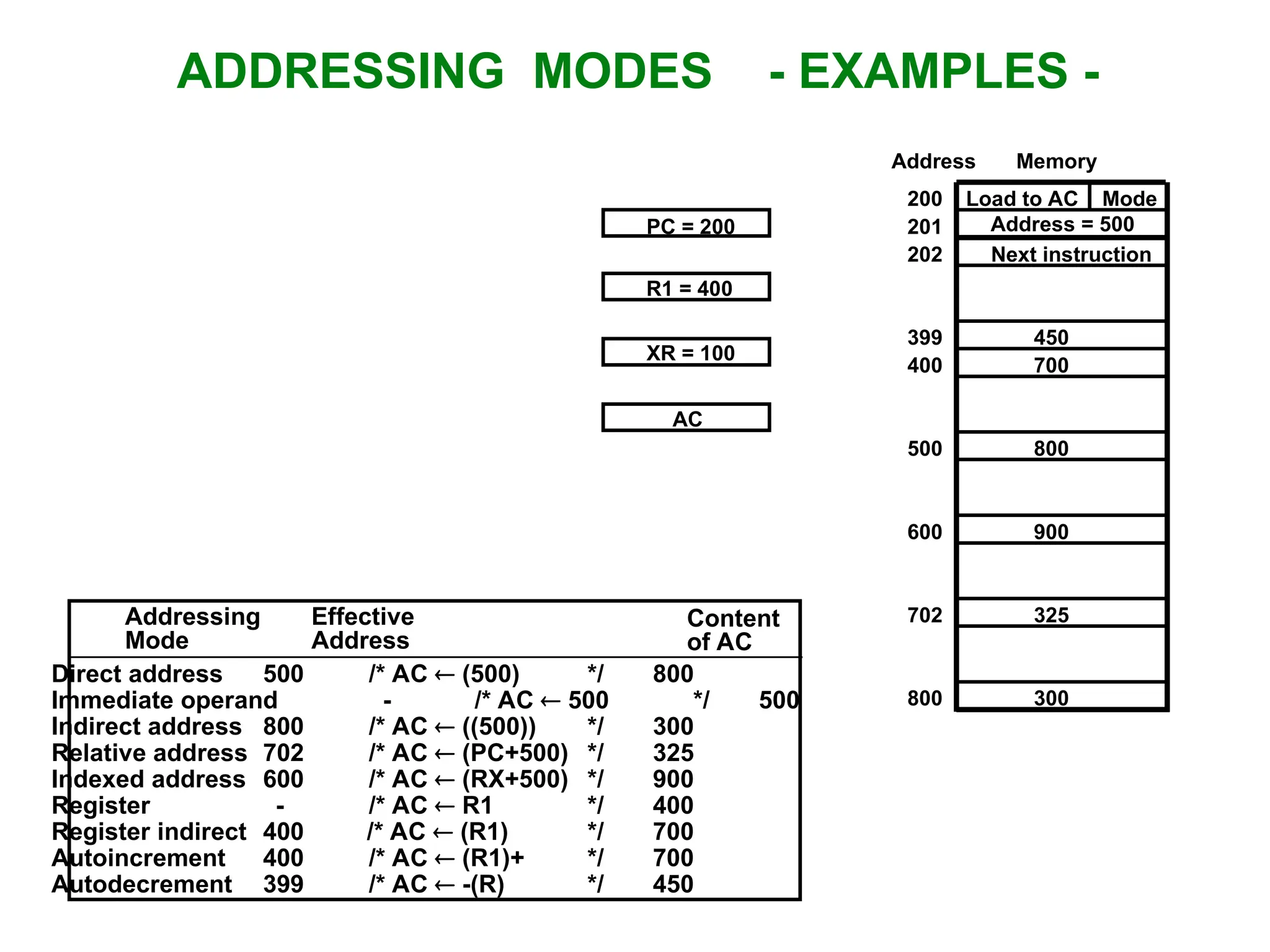
ADDRESSING MODES -EXAMPLES - Addressing Mode Effective Address Content of AC Direct address 500 /* AC (500) */ 800 Immediate operand - /* AC 500 */ 500 Indirect address 800 /* AC ((500)) */ 300 Relative address 702 /* AC (PC+500) */ 325 Indexed address 600 /* AC (RX+500) */ 900 Register - /* AC R1 */ 400 Register indirect 400 /* AC (R1) */ 700 Autoincrement 400 /* AC (R1)+ */ 700 Autodecrement 399 /* AC -(R) */ 450 Load to AC Mode Address = 500 Next instruction 200 201 202 399 400 450 700 500 800 600 900 702 325 800 300 Memory Address PC = 200 R1 = 400 XR = 100 AC
20.
DATA TRANSFER INSTRUCTIONS LoadLD Store ST Move MOV Exchange XCH Input IN Output OUT Push PUSH Pop POP Name Mnemonic • Typical Data Transfer Instructions Direct address LD ADR AC M[ADR] Indirect address LD @ADR AC M[M[ADR]] Relative address LD $ADR AC M[PC + ADR] Immediate operand LD #NBR AC NBR Index addressing LD ADR(X) AC M[ADR + XR] Register LD R1 AC R1 Register indirect LD (R1) AC M[R1] Autoincrement LD (R1)+ AC M[R1], R1 R1 + 1 Autodecrement LD -(R1) R1 R1 - 1, AC M[R1] Mode Assembly Convention Register Transfer • Data Transfer Instructions with Different Addressing Modes
21.
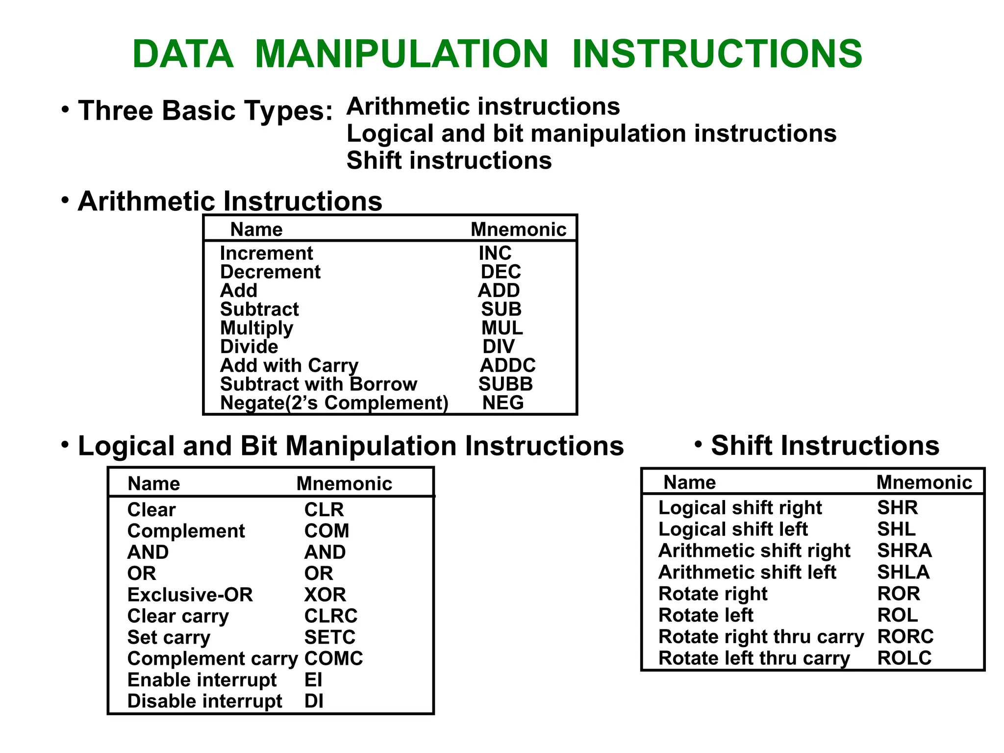
DATA MANIPULATION INSTRUCTIONS •Three Basic Types: Arithmetic instructions Logical and bit manipulation instructions Shift instructions • Arithmetic Instructions Name Mnemonic Clear CLR Complement COM AND AND OR OR Exclusive-OR XOR Clear carry CLRC Set carry SETC Complement carry COMC Enable interrupt EI Disable interrupt DI Name Mnemonic Logical shift right SHR Logical shift left SHL Arithmetic shift right SHRA Arithmetic shift left SHLA Rotate right ROR Rotate left ROL Rotate right thru carry RORC Rotate left thru carry ROLC Name Mnemonic • Logical and Bit Manipulation Instructions • Shift Instructions Increment INC Decrement DEC Add ADD Subtract SUB Multiply MUL Divide DIV Add with Carry ADDC Subtract with Borrow SUBB Negate(2’s Complement) NEG
22.
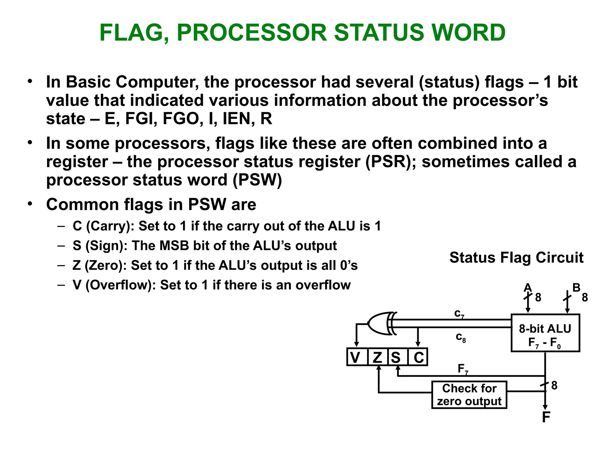
FLAG, PROCESSOR STATUSWORD • In Basic Computer, the processor had several (status) flags – 1 bit value that indicated various information about the processor’s state – E, FGI, FGO, I, IEN, R • In some processors, flags like these are often combined into a register – the processor status register (PSR); sometimes called a processor status word (PSW) • Common flags in PSW are – C (Carry): Set to 1 if the carry out of the ALU is 1 – S (Sign): The MSB bit of the ALU’s output – Z (Zero): Set to 1 if the ALU’s output is all 0’s – V (Overflow): Set to 1 if there is an overflow Status Flag Circuit c7 c8 A B 8 8 8-bit ALU V Z S C F7 F7 - F0 8 F Check for zero output
23.
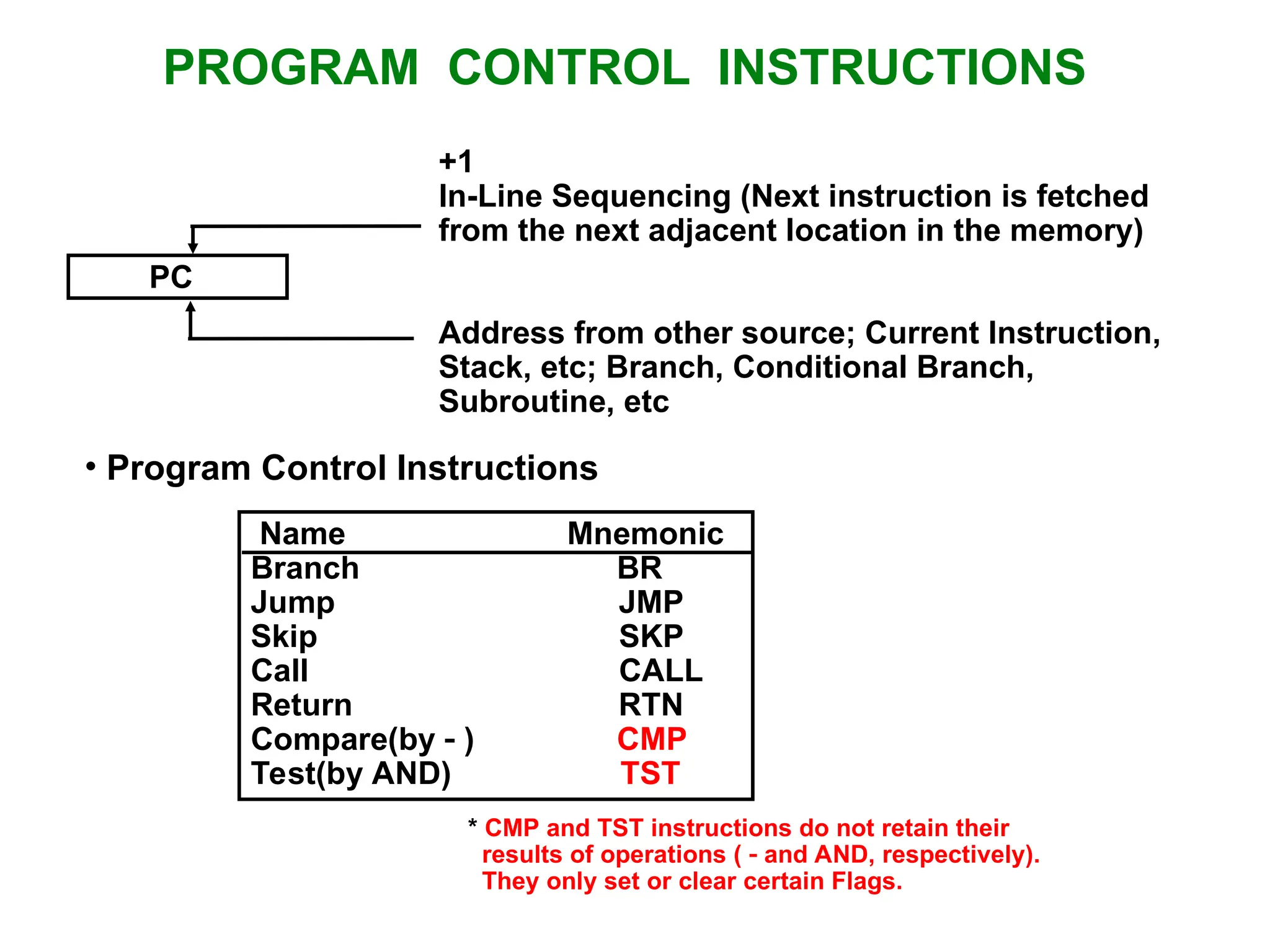
PROGRAM CONTROL INSTRUCTIONS PC +1 In-LineSequencing (Next instruction is fetched from the next adjacent location in the memory) Address from other source; Current Instruction, Stack, etc; Branch, Conditional Branch, Subroutine, etc • Program Control Instructions Name Mnemonic Branch BR Jump JMP Skip SKP Call CALL Return RTN Compare(by ) CMP Test(by AND) TST * CMP and TST instructions do not retain their results of operations ( and AND, respectively). They only set or clear certain Flags.
24.
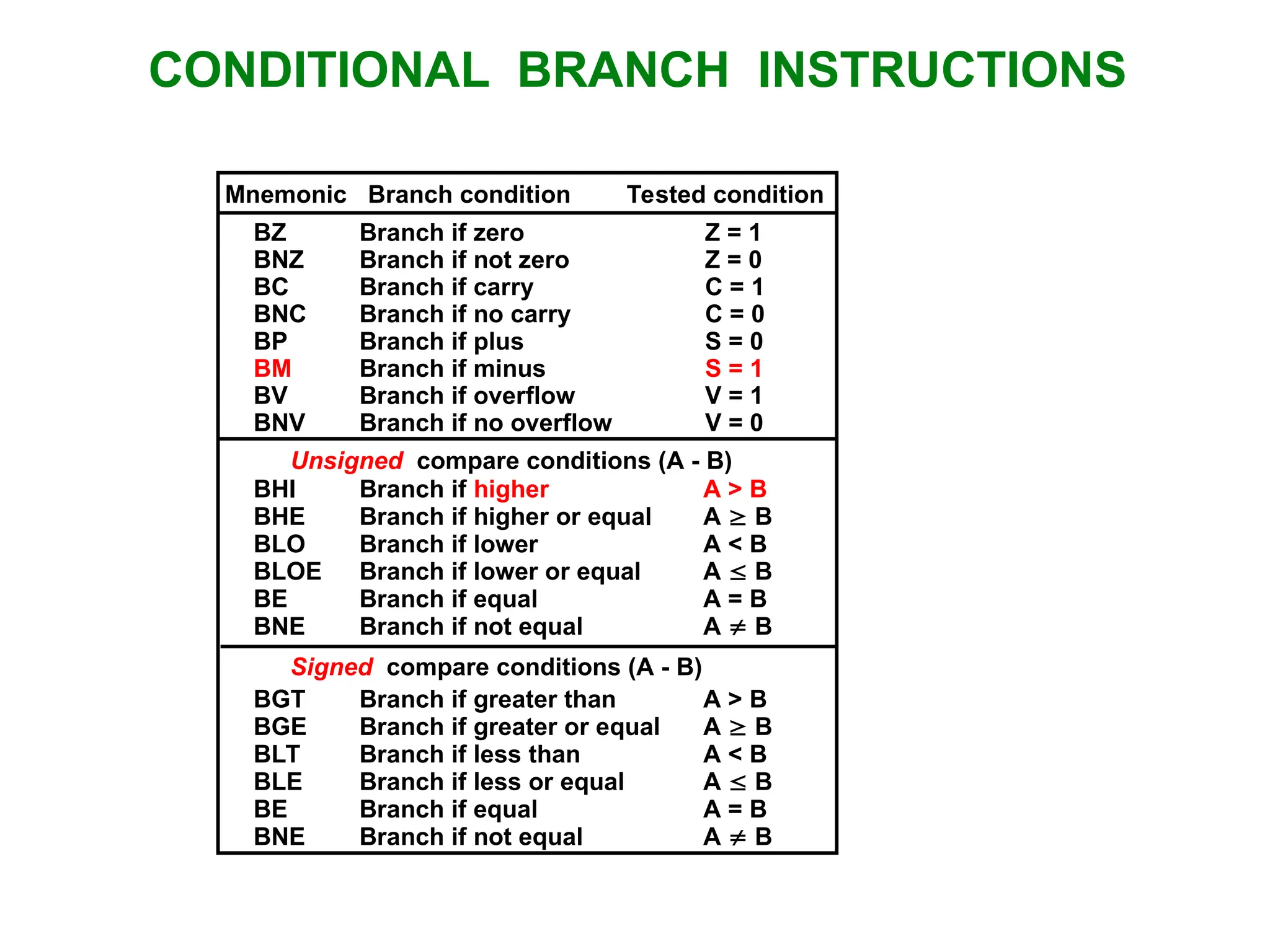
CONDITIONAL BRANCH INSTRUCTIONS BZBranch if zero Z = 1 BNZ Branch if not zero Z = 0 BC Branch if carry C = 1 BNC Branch if no carry C = 0 BP Branch if plus S = 0 BM Branch if minus S = 1 BV Branch if overflow V = 1 BNV Branch if no overflow V = 0 BHI Branch if higher A > B BHE Branch if higher or equal A B BLO Branch if lower A < B BLOE Branch if lower or equal A B BE Branch if equal A = B BNE Branch if not equal A B BGT Branch if greater than A > B BGE Branch if greater or equal A B BLT Branch if less than A < B BLE Branch if less or equal A B BE Branch if equal A = B BNE Branch if not equal A B Unsigned compare conditions (A - B) Signed compare conditions (A - B) Mnemonic Branch condition Tested condition
25.
SUBROUTINE CALL ANDRETURN Call subroutine Jump to subroutine Branch to subroutine Branch and save return address • Fixed Location in the subroutine (Memory) • Fixed Location in memory • In a processor Register • In memory stack - most efficient way • Subroutine Call • Two Most Important Operations are Implied; * Branch to the beginning of the Subroutine - Same as the Branch or Conditional Branch * Save the Return Address to get the address of the location in the Calling Program upon exit from the Subroutine • Locations for storing Return Address CALL SP SP - 1 M[SP] PC PC EA RTN PC M[SP] SP SP + 1
26.
COMPLEX INSTRUCTION SETCOMPUTER • Continuing growth in semiconductor memory and microprogramming A much richer and complicated instruction sets and addressing modes Complex Instruction Set Computers (CISC) • Richer instruction sets would simplify compilers • Richer instruction sets would move as much functions to the hardware as possible • Richer instruction sets would improve architecture quality • One goal for CISC machines was to have a machine language instruction to match each high-level language statement type
27.
VARIABLE LENGTH INSTRUCTIONS •The large number of instructions means a greater number of bits to specify them • The large number of instructions and addressing modes led CISC machines to have variable length instruction formats • In order to manage this large number of opcodes efficiently, they were encoded with different lengths: – More frequently used instructions were encoded using short opcodes. – Less frequently used ones were assigned longer opcodes. • Also, multiple operand instructions could specify different addressing modes for each operand – For example, » Operand 1 could be a directly addressed register, » Operand 2 could be an indirectly addressed memory location, » Operand 3 (the destination) could be an indirectly addressed register. • All of this led to the need to have different length instructions in different situations, depending on the opcode and operands used
28.
VARIABLE LENGTH INSTRUCTIONS •For example, an instruction that only specifies register operands may only be two bytes in length – One byte to specify the instruction and addressing mode – One byte to specify the source and destination registers. • An instruction that specifies memory addresses for operands may need five bytes – One byte to specify the instruction and addressing mode – Two bytes to specify each memory address » Maybe more if there’s a large amount of memory. • Variable length instructions greatly complicate the fetch and decode problem for a processor • The circuitry to recognize the various instructions and to properly fetch the required number of bytes for operands is very complex
29.
COMPLEX INSTRUCTION SETCOMPUTER • Another characteristic of CISC computers is that they have instructions that act directly on memory addresses – For example, ADD L1, L2, L3 that takes the contents of M[L1] adds it to the contents of M[L2] and stores the result in location M[L3] • An instruction like this takes three memory access cycles to execute • The problems with CISC computers are – The complexity of the design may slow down the processor, – The complexity of the design may result in costly errors in the processor design and implementation, – Many of the instructions and addressing modes are used rarely, if ever
30.
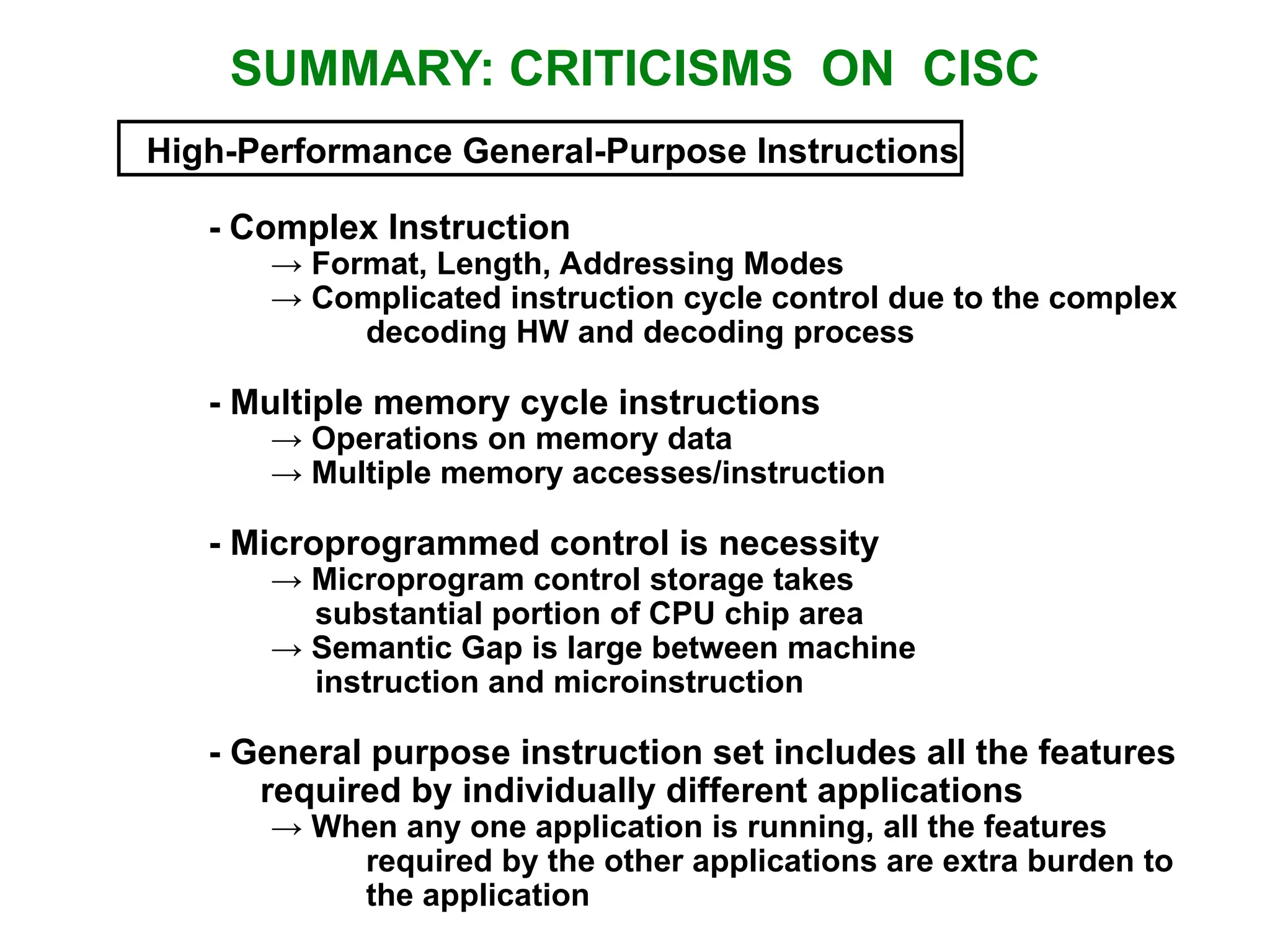
SUMMARY: CRITICISMS ONCISC High-Performance General-Purpose Instructions - Complex Instruction → Format, Length, Addressing Modes → Complicated instruction cycle control due to the complex decoding HW and decoding process - Multiple memory cycle instructions → Operations on memory data → Multiple memory accesses/instruction - Microprogrammed control is necessity → Microprogram control storage takes substantial portion of CPU chip area → Semantic Gap is large between machine instruction and microinstruction - General purpose instruction set includes all the features required by individually different applications → When any one application is running, all the features required by the other applications are extra burden to the application
31.
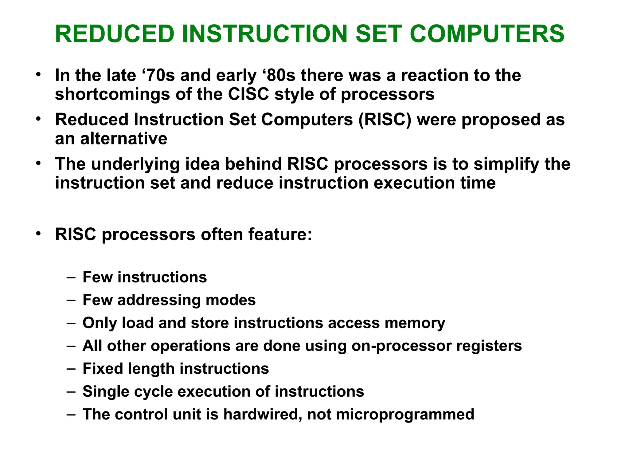
REDUCED INSTRUCTION SETCOMPUTERS • In the late ‘70s and early ‘80s there was a reaction to the shortcomings of the CISC style of processors • Reduced Instruction Set Computers (RISC) were proposed as an alternative • The underlying idea behind RISC processors is to simplify the instruction set and reduce instruction execution time • RISC processors often feature: – Few instructions – Few addressing modes – Only load and store instructions access memory – All other operations are done using on-processor registers – Fixed length instructions – Single cycle execution of instructions – The control unit is hardwired, not microprogrammed
32.
REDUCED INSTRUCTION SETCOMPUTERS • Since all but the load and store instructions use only registers for operands, only a few addressing modes are needed • By having all instructions the same length, reading them in is easy and fast • The fetch and decode stages are simple, looking much more like Mano’s Basic Computer than a CISC machine • The instruction and address formats are designed to be easy to decode • Unlike the variable length CISC instructions, the opcode and register fields of RISC instructions can be decoded simultaneously • The control logic of a RISC processor is designed to be simple and fast • The control logic is simple because of the small number of instructions and the simple addressing modes • The control logic is hardwired, rather than microprogrammed, because hardwired control is faster
33.
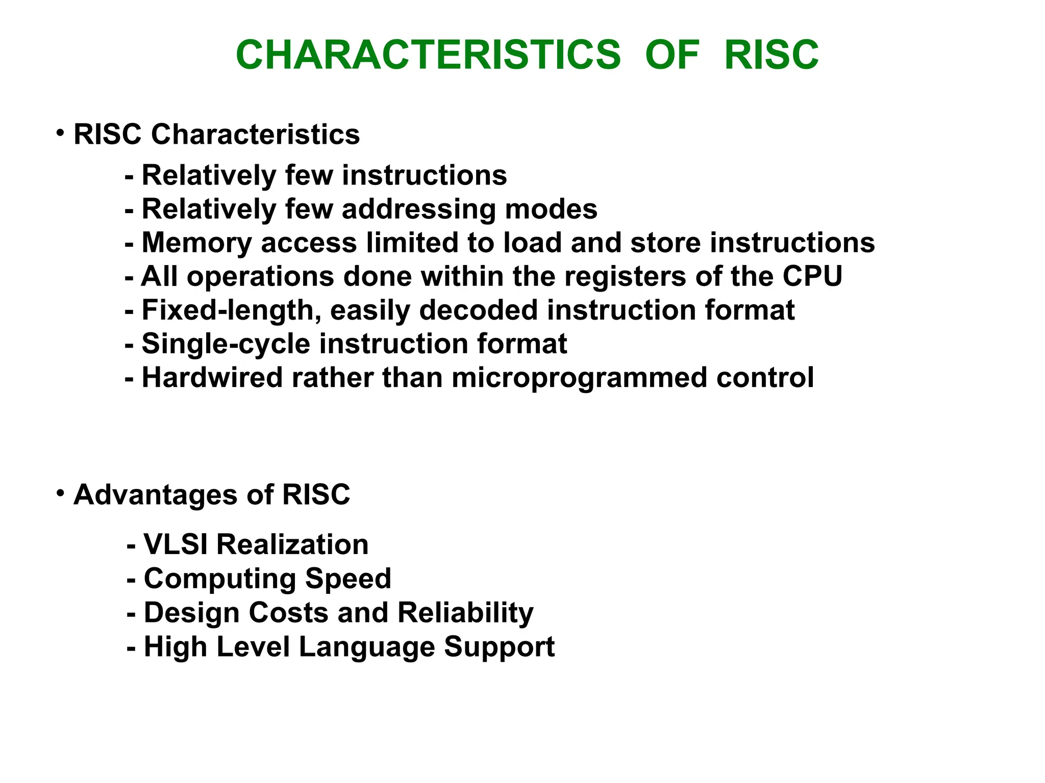
CHARACTERISTICS OF RISC •RISC Characteristics • Advantages of RISC - VLSI Realization - Computing Speed - Design Costs and Reliability - High Level Language Support - Relatively few instructions - Relatively few addressing modes - Memory access limited to load and store instructions - All operations done within the registers of the CPU - Fixed-length, easily decoded instruction format - Single-cycle instruction format - Hardwired rather than microprogrammed control
34.
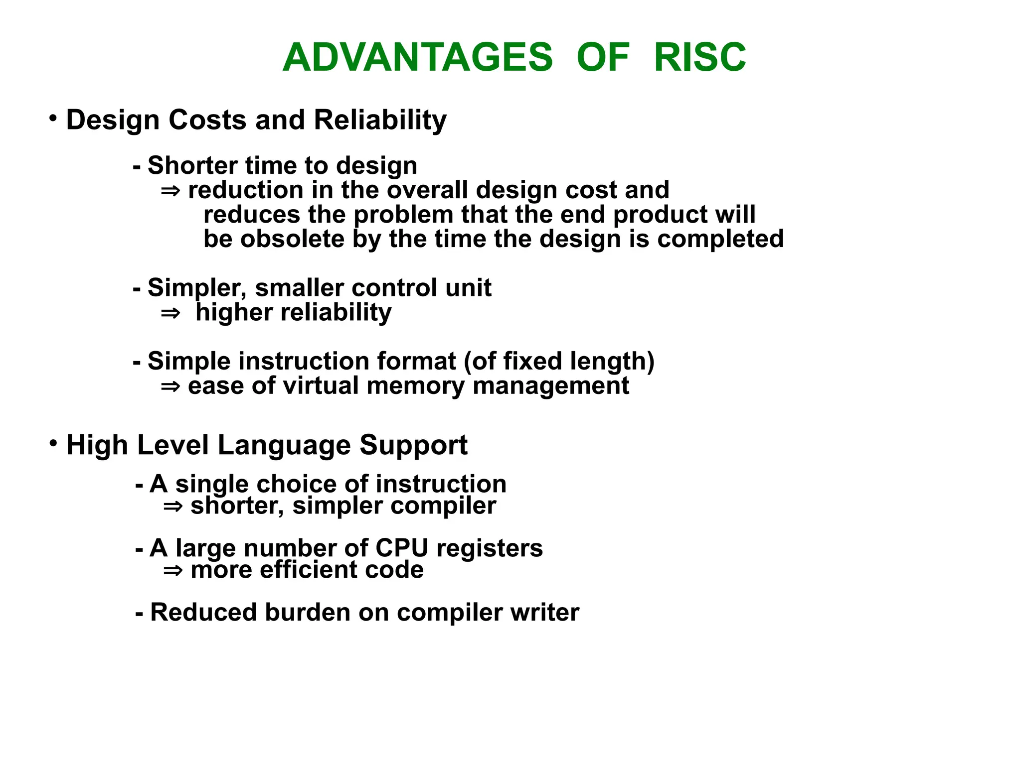
ADVANTAGES OF RISC •Design Costs and Reliability - Shorter time to design reduction in the overall design cost and reduces the problem that the end product will be obsolete by the time the design is completed - Simpler, smaller control unit higher reliability - Simple instruction format (of fixed length) ease of virtual memory management • High Level Language Support - A single choice of instruction shorter, simpler compiler - A large number of CPU registers more efficient code - Reduced burden on compiler writer
#26 CISC Designed with a large set of complex instructions, each capable of performing multiple operations in a single instruction. Complex Instructions: memory access + arithmetic in one step Fewer Instructions Executed: Since each instruction does more Instructions vary in size, making decoding more complex. More Addressing Modes Heavy Use of Microcode CISC dominates in high-performance computing and legacy systems (Windows PCs, gaming computers). ADD AX, [var]
#31 RISC processors use a simplified and uniform instruction set, where instructions are designed to execute in a single clock cycle. Simple and Uniform Instructions: Each instruction does only one operation (e.g., load, store, add). Fixed-Length Instructions: Simplifies instruction decoding Only load/store instructions access memory; arithmetic operations use registers. More General-Purpose Registers: Reduces memory access Pipelining-Friendly: Optimized for parallel execution. RISC is preferred for power-efficient devices (smartphones, embedded systems, Apple M-series chips). LDR R0, [R1] ; ADD R0, R0, R2 ; STR R0, [R1] ;
![OPERATION OF CONTROL UNIT The control unit Directs the information flow through ALU by - Selecting various Components in the system - Selecting the Function of ALU Example: R1 R2 + R3 [1] MUX A selector (SELA): BUS A R2 [2] MUX B selector (SELB): BUS B R3 [3] ALU operation selector (OPR): ALU to ADD [4] Decoder destination selector (SELD): R1 Out Bus Control Word Encoding of register selection fields Binary Code SELA SELB SELD 000 Input Input None 001 R1 R1 R1 010 R2 R2 R2 011 R3 R3 R3 100 R4 R4 R4 101 R5 R5 R5 110 R6 R6 R6 111 R7 R7 R7 SELA SELB SELD OPR 3 3 3 5](https://image.slidesharecdn.com/ch-3cpu-250226052425-9597cd76/75/CH-3-CPU-Computer-architecture-and-organization-ppt-5-2048.jpg)
![REGISTER STACK ORGANIZATION Register Stack Push, Pop operations /* Initially, SP = 0, EMPTY = 1, FULL = 0 */ PUSH POP SP SP + 1 DR M[SP] M[SP] DR SP SP 1 If (SP = 0) then (FULL 1) If (SP = 0) then (EMPTY 1) EMPTY 0 FULL 0 Stack - Very useful feature for nested subroutines, nested interrupt services - Also efficient for arithmetic expression evaluation - Storage which can be accessed in LIFO - Pointer: SP - Only PUSH and POP operations are applicable A B C 0 1 2 3 4 63 Address FULL EMPTY SP DR Flags Stack pointer stack 6 bits](https://image.slidesharecdn.com/ch-3cpu-250226052425-9597cd76/75/CH-3-CPU-Computer-architecture-and-organization-ppt-7-2048.jpg)
![MEMORY STACK ORGANIZATION - A portion of memory is used as a stack with a processor register as a stack pointer - PUSH: SP SP - 1 M[SP] DR - POP: DR M[SP] SP SP + 1 Memory with Program, Data, and Stack Segments 4001 4000 3999 3998 3997 3000 Data (operands) Program (instructions) 1000 PC AR SP stack Stack grows In this direction - Most computers do not provide hardware to check stack overflow (full stack) or underflow (empty stack) must be done in software](https://image.slidesharecdn.com/ch-3cpu-250226052425-9597cd76/75/CH-3-CPU-Computer-architecture-and-organization-ppt-8-2048.jpg)
![INSTRUCTION FORMAT OP-code field - specifies the operation to be performed Address field - designates memory address(es) or a processor register(s) Mode field - determines how the address field is to be interpreted (to get effective address or the operand) • The number of address fields in the instruction format depends on the internal organization of CPU • The three most common CPU organizations: Single accumulator organization: ADD X /* AC AC + M[X] */ General register organization: ADD R1, R2, R3 /* R1 R2 + R3 */ ADD R1, R2 /* R1 R1 + R2 */ MOV R1, R2 /* R1 R2 */ ADD R1, X /* R1 R1 + M[X] */ Stack organization: PUSH X /* TOS M[X] */ ADD • Instruction Fields](https://image.slidesharecdn.com/ch-3cpu-250226052425-9597cd76/75/CH-3-CPU-Computer-architecture-and-organization-ppt-11-2048.jpg)
![• Three-Address Instructions Program to evaluate X = (A + B) * (C + D) : ADD R1, A, B /* R1 M[A] + M[B] */ ADD R2, C, D /* R2 M[C] + M[D] */ MUL X, R1, R2 /* M[X] R1 * R2 */ - Results in short programs (Advantage) - Instruction becomes long (many bits) • Two-Address Instructions Program to evaluate X = (A + B) * (C + D) : MOV R1, A /* R1 M[A] */ ADD R1, B /* R1 R1 + M[A] */ MOV R2, C /* R2 M[C] */ ADD R2, D /* R2 R2 + M[D] */ MUL R1, R2 /* R1 R1 * R2 */ MOV X, R1 /* M[X] R1 */ THREE, AND TWO-ADDRESS INSTRUCTIONS](https://image.slidesharecdn.com/ch-3cpu-250226052425-9597cd76/75/CH-3-CPU-Computer-architecture-and-organization-ppt-12-2048.jpg)
![ONE, AND ZERO-ADDRESS INSTRUCTIONS • One-Address Instructions - Use an implied AC register for all data manipulation - Program to evaluate X = (A + B) * (C + D) : LOAD A /* AC M[A] */ ADD B /* AC AC + M[B] */ STORE T /* M[T] AC */ LOAD C /* AC M[C] */ ADD D /* AC AC + M[D] */ MUL T /* AC AC * M[T] */ STORE X /* M[X] AC */ • Zero-Address Instructions - Can be found in a stack-organized computer - Program to evaluate X = (A + B) * (C + D) : PUSH A /* TOS A */ PUSH B /* TOS B */ ADD /* TOS (A + B) */ PUSH C /* TOS C */ PUSH D /* TOS D */ ADD /* TOS (C + D) */ MUL /* TOS (C + D) * (A + B) */ POP X /* M[X] TOS */](https://image.slidesharecdn.com/ch-3cpu-250226052425-9597cd76/75/CH-3-CPU-Computer-architecture-and-organization-ppt-13-2048.jpg)
![TYPES OF ADDRESSING MODES • Implied Mode Address of the operands are specified implicitly in the definition of the instruction - No need to specify address in the instruction - EA = AC, or EA = Stack[SP] - Examples from Basic Computer CLA, CME, INP • Immediate Mode Instead of specifying the address of the operand, operand itself is specified - No need to specify address in the instruction - However, operand itself needs to be specified - Sometimes, require more bits than the address - Fast to acquire an operand](https://image.slidesharecdn.com/ch-3cpu-250226052425-9597cd76/75/CH-3-CPU-Computer-architecture-and-organization-ppt-15-2048.jpg)
![TYPES OF ADDRESSING MODES • Register Mode Address specified in the instruction is the register address - Designated operand need to be in a register - Shorter address than the memory address - Saving address field in the instruction - Faster to acquire an operand than the memory addressing - EA = IR(R) (IR(R): Register field of IR) • Register Indirect Mode Instruction specifies a register which contains the memory address of the operand - Saving instruction bits since register address is shorter than the memory address - Slower to acquire an operand than both the register addressing or memory addressing - EA = [IR(R)] ([x]: Content of x) • Autoincrement or Autodecrement Mode - When the address in the register is used to access memory, the value in the register is incremented or decremented by 1 automatically](https://image.slidesharecdn.com/ch-3cpu-250226052425-9597cd76/75/CH-3-CPU-Computer-architecture-and-organization-ppt-16-2048.jpg)
![TYPES OF ADDRESSING MODES • Direct Address Mode Instruction specifies the memory address which can be used directly to access the memory - Faster than the other memory addressing modes - Too many bits are needed to specify the address for a large physical memory space - EA = IR(addr) (IR(addr): address field of IR) • Indirect Addressing Mode The address field of an instruction specifies the address of a memory location that contains the address of the operand - When the abbreviated address is used large physical memory can be addressed with a relatively small number of bits - Slow to acquire an operand because of an additional memory access - EA = M[IR(address)]](https://image.slidesharecdn.com/ch-3cpu-250226052425-9597cd76/75/CH-3-CPU-Computer-architecture-and-organization-ppt-17-2048.jpg)
![DATA TRANSFER INSTRUCTIONS Load LD Store ST Move MOV Exchange XCH Input IN Output OUT Push PUSH Pop POP Name Mnemonic • Typical Data Transfer Instructions Direct address LD ADR AC M[ADR] Indirect address LD @ADR AC M[M[ADR]] Relative address LD $ADR AC M[PC + ADR] Immediate operand LD #NBR AC NBR Index addressing LD ADR(X) AC M[ADR + XR] Register LD R1 AC R1 Register indirect LD (R1) AC M[R1] Autoincrement LD (R1)+ AC M[R1], R1 R1 + 1 Autodecrement LD -(R1) R1 R1 - 1, AC M[R1] Mode Assembly Convention Register Transfer • Data Transfer Instructions with Different Addressing Modes](https://image.slidesharecdn.com/ch-3cpu-250226052425-9597cd76/75/CH-3-CPU-Computer-architecture-and-organization-ppt-20-2048.jpg)
![SUBROUTINE CALL AND RETURN Call subroutine Jump to subroutine Branch to subroutine Branch and save return address • Fixed Location in the subroutine (Memory) • Fixed Location in memory • In a processor Register • In memory stack - most efficient way • Subroutine Call • Two Most Important Operations are Implied; * Branch to the beginning of the Subroutine - Same as the Branch or Conditional Branch * Save the Return Address to get the address of the location in the Calling Program upon exit from the Subroutine • Locations for storing Return Address CALL SP SP - 1 M[SP] PC PC EA RTN PC M[SP] SP SP + 1](https://image.slidesharecdn.com/ch-3cpu-250226052425-9597cd76/75/CH-3-CPU-Computer-architecture-and-organization-ppt-25-2048.jpg)
![COMPLEX INSTRUCTION SET COMPUTER • Another characteristic of CISC computers is that they have instructions that act directly on memory addresses – For example, ADD L1, L2, L3 that takes the contents of M[L1] adds it to the contents of M[L2] and stores the result in location M[L3] • An instruction like this takes three memory access cycles to execute • The problems with CISC computers are – The complexity of the design may slow down the processor, – The complexity of the design may result in costly errors in the processor design and implementation, – Many of the instructions and addressing modes are used rarely, if ever](https://image.slidesharecdn.com/ch-3cpu-250226052425-9597cd76/75/CH-3-CPU-Computer-architecture-and-organization-ppt-29-2048.jpg)