Topics to becovered Introduction General Register Organization Stack Organization Instruction format Addressing Modes Data transfer and manipulation Program Control Reduced Instruction Set Computer (RISC) Complex Instruction Set Computer (CISC)
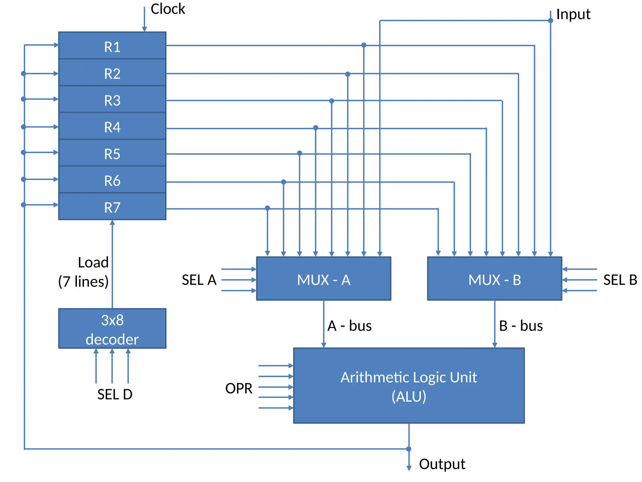
R1 R2 R3 R4 R5 R6 R7 MUX - AMUX - B Arithmetic Logic Unit (ALU) 3x8 decoder Clock Input Output SEL B SEL A SEL D OPR Load (7 lines) A - bus B - bus
5.
General Register Organization Example: R1 R2 + R3 To perform the above operation, the control must provide binary selection variables to the following selector inputs: 1. MUX A selector (SELA): to place the content of R2 into bus A. 2. MUX B selector (SELB): to place the content of R3 into bus B. 3. ALU operation selector (OPR): to provide the arithmetic addition A + B. 4. Decoder destination selector (SELD): to transfer the content of the output bus into R1. Control Word: SELA SELB SELD OPR
6.
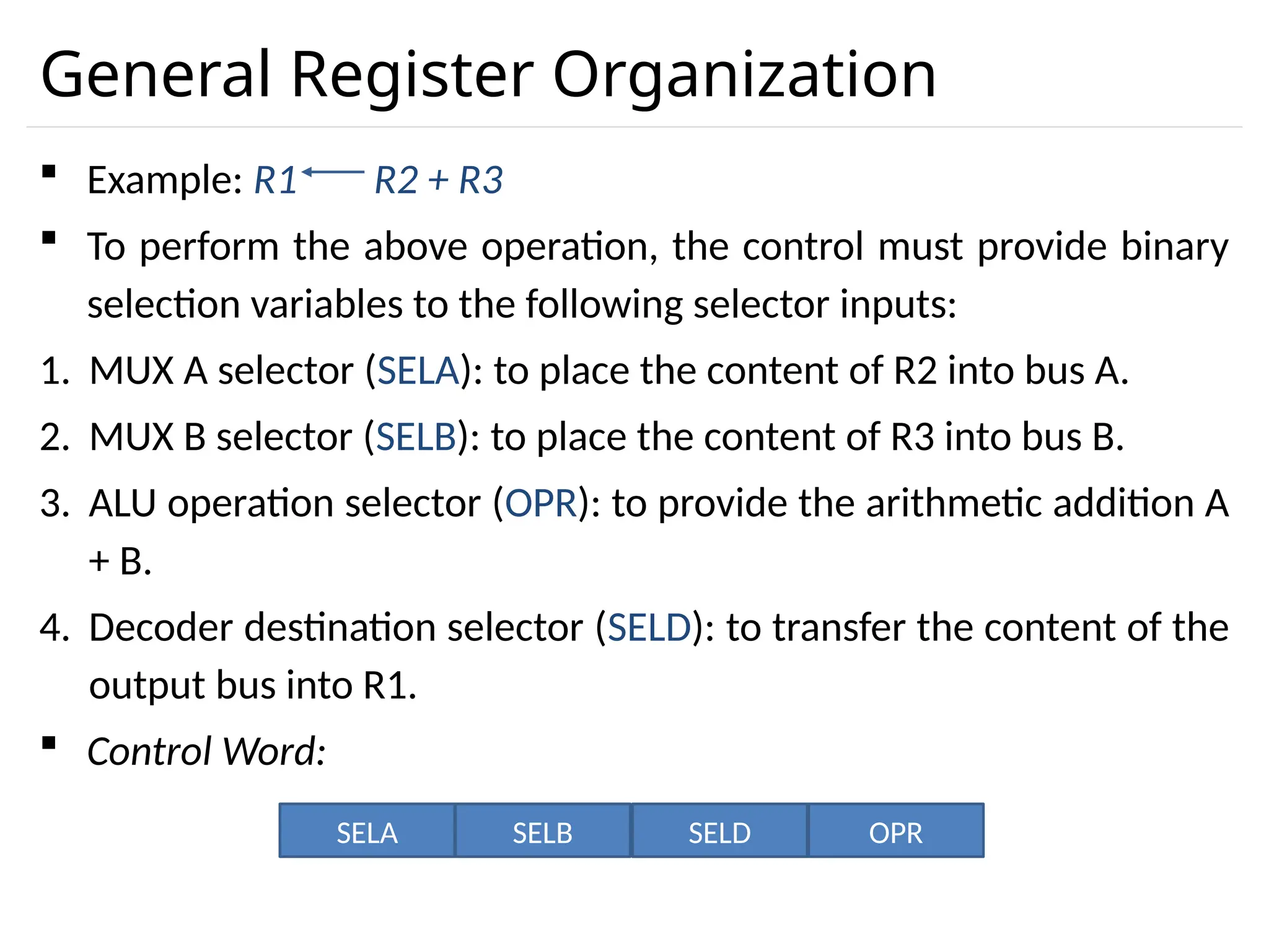
General Register Organization Binary Code SELASELB SELD 000 Input Input None 001 R1 R1 R1 010 R2 R2 R2 011 R3 R3 R3 100 R4 R4 R4 101 R5 R5 R5 110 R6 R6 R6 111 R7 R7 R7 OPR Select Operation Symbol 00000 Transfer A TSFA 00001 Increment A INCA 00010 A + B ADD 00101 A – B SUB 00110 Decrement A DECA 01000 A and B AND 01010 A or B OR 01100 A xor B XOR 01110 Complement A COMA 10000 Shift right A SHRA 11000 Shift left A SHLA Encoding of Register Selection Fields Encoding of ALU Operations
Stack Organization Astack is a storage device that stores information in such a manner that the item stored last is the first item retrieved (LIFO). The register that holds the address for the stack is called a stack pointer (SP) because its value always points at the top item in the stack. The physical registers of a stack are always available for reading or writing. It is the content of the word that is inserted or deleted. There are two types of stack organization 1. Register stack – built using registers 2. Memory stack – logical part of memory allocated as stack
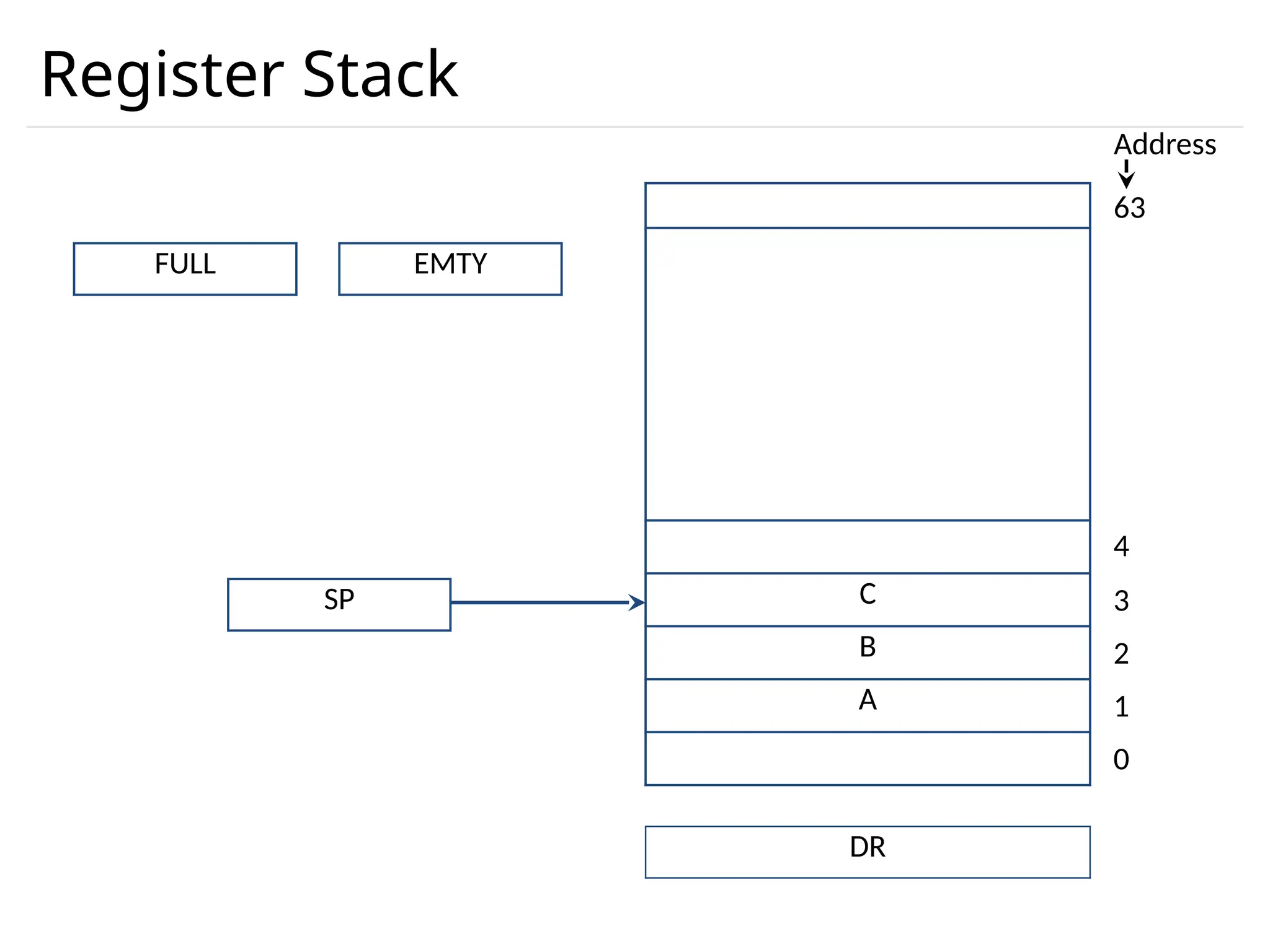
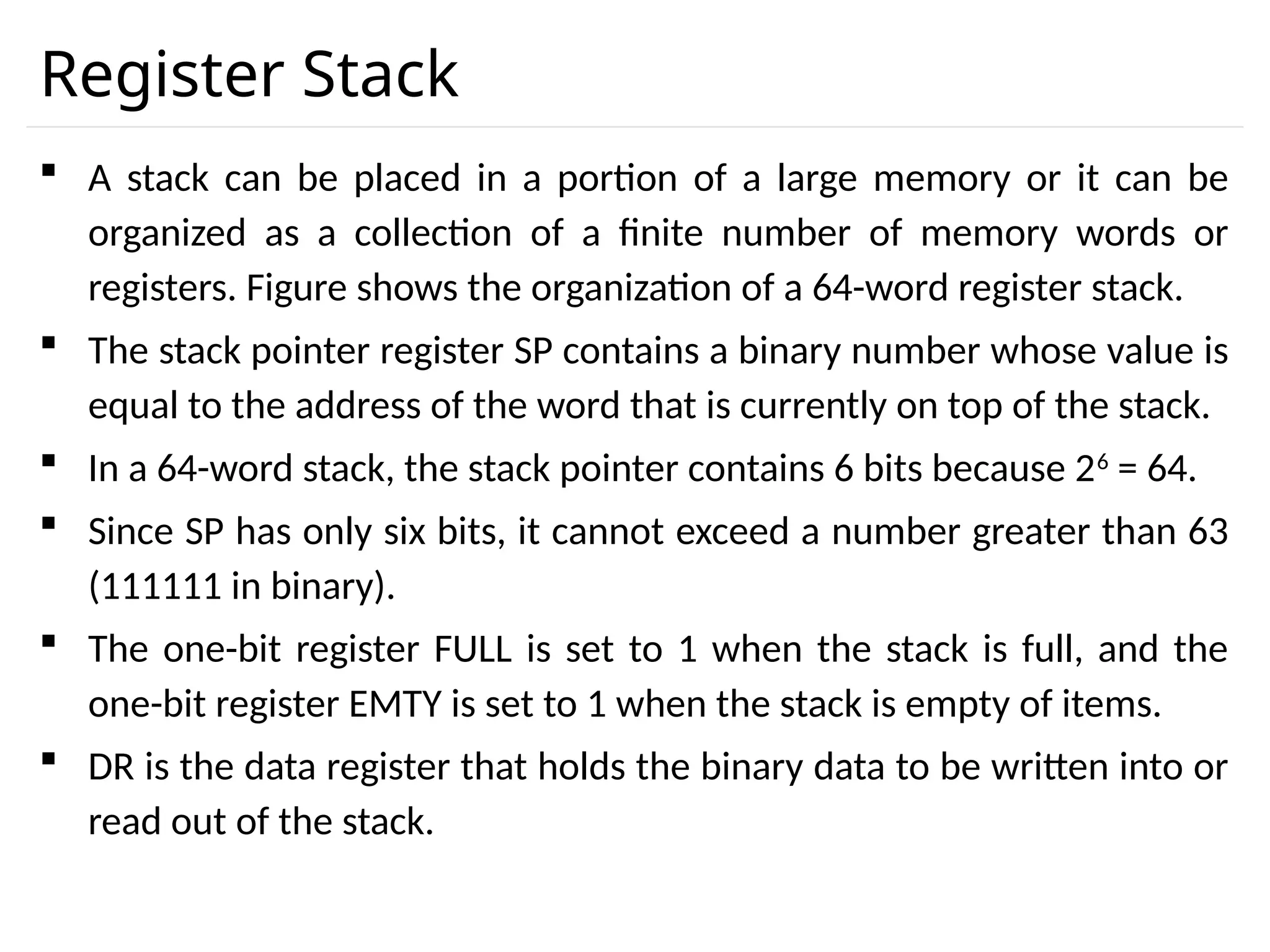
Register Stack Astack can be placed in a portion of a large memory or it can be organized as a collection of a finite number of memory words or registers. Figure shows the organization of a 64-word register stack. The stack pointer register SP contains a binary number whose value is equal to the address of the word that is currently on top of the stack. In a 64-word stack, the stack pointer contains 6 bits because 26 = 64. Since SP has only six bits, it cannot exceed a number greater than 63 (111111 in binary). The one-bit register FULL is set to 1 when the stack is full, and the one-bit register EMTY is set to 1 when the stack is empty of items. DR is the data register that holds the binary data to be written into or read out of the stack.
11.
Register Stack PUSHOperation SP ← SP + 1 M[SP] ← DR IF (SP= 0) then (FULL ← 1) EMTY ← 0 POP Operation DR ← M[SP] SP ← SP - 1 IF (SP= 0) then (EMTY ← 1) FULL ← 0
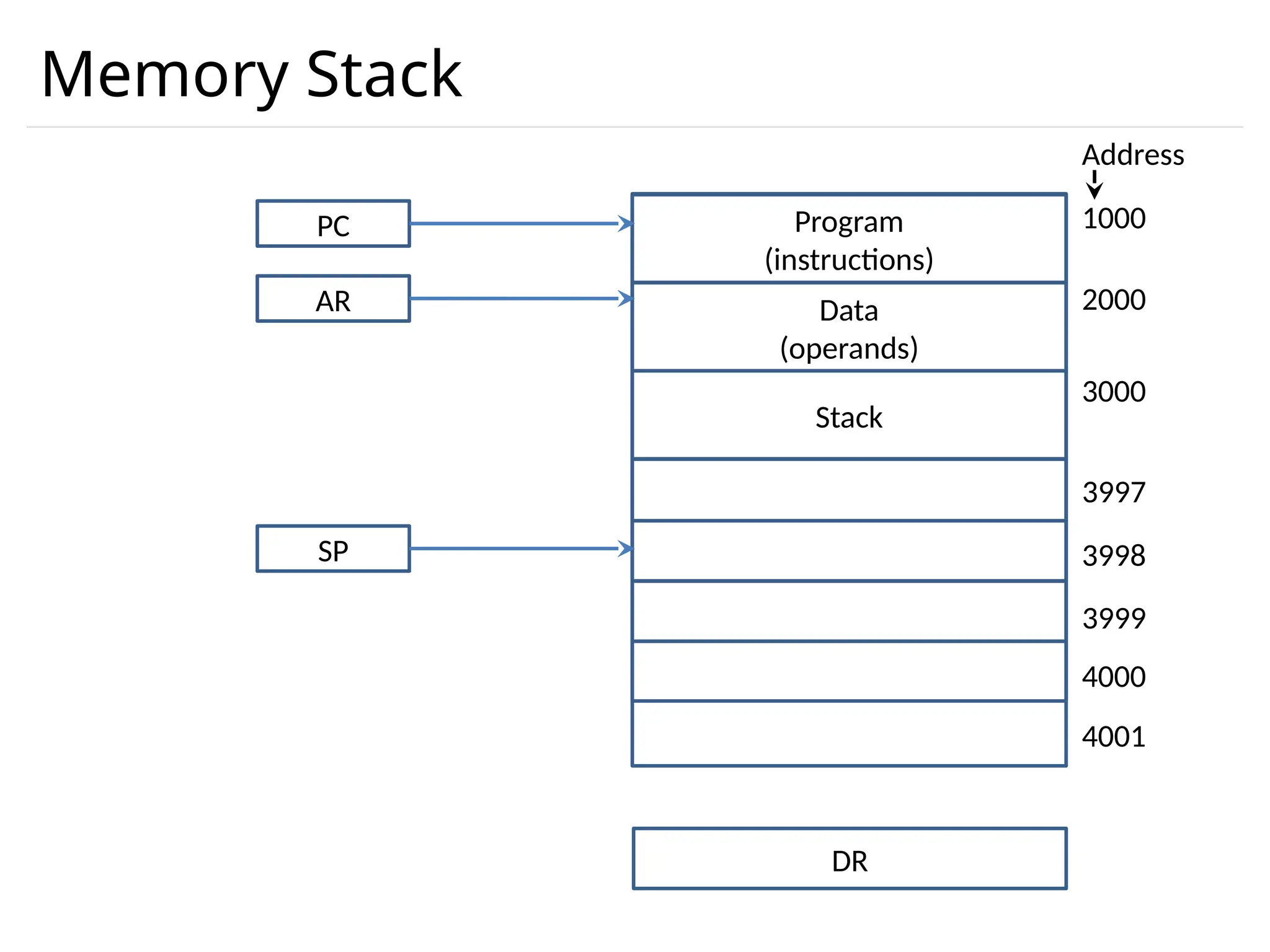
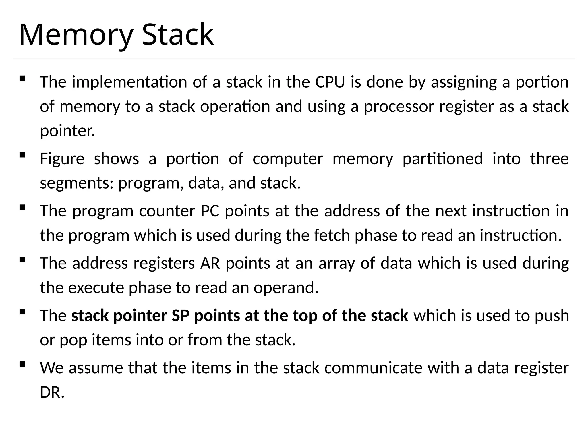
Memory Stack Theimplementation of a stack in the CPU is done by assigning a portion of memory to a stack operation and using a processor register as a stack pointer. Figure shows a portion of computer memory partitioned into three segments: program, data, and stack. The program counter PC points at the address of the next instruction in the program which is used during the fetch phase to read an instruction. The address registers AR points at an array of data which is used during the execute phase to read an operand. The stack pointer SP points at the top of the stack which is used to push or pop items into or from the stack. We assume that the items in the stack communicate with a data register DR.
14.
Memory Stack PUSHOperation SP ← SP - 1 M[SP] ← DR POP Operation DR ← M[SP] SP ← SP + 1
15.
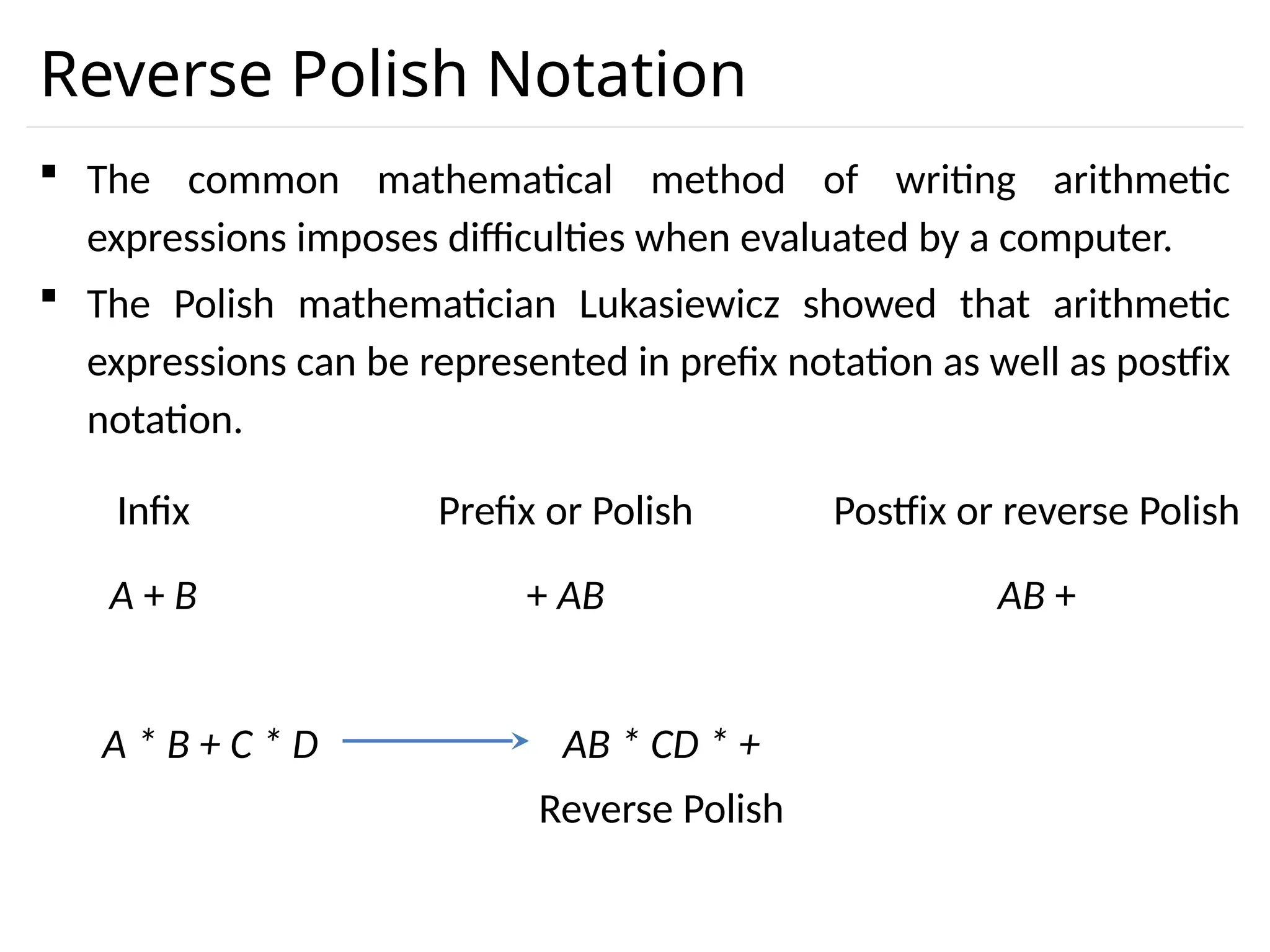
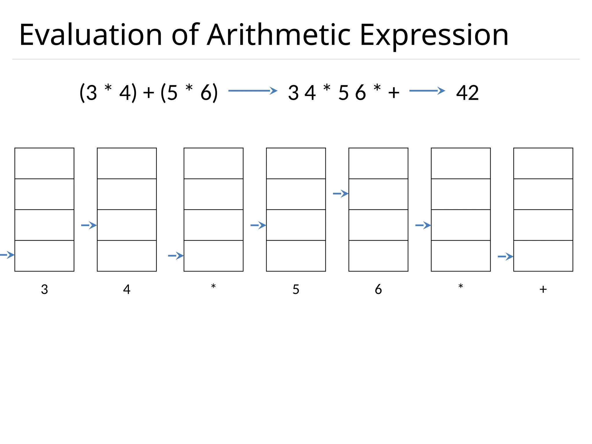
Reverse Polish Notation The common mathematical method of writing arithmetic expressions imposes difficulties when evaluated by a computer. The Polish mathematician Lukasiewicz showed that arithmetic expressions can be represented in prefix notation as well as postfix notation. A + B + AB AB + Infix Prefix or Polish Postfix or reverse Polish A * B + C * D AB * CD * + Reverse Polish
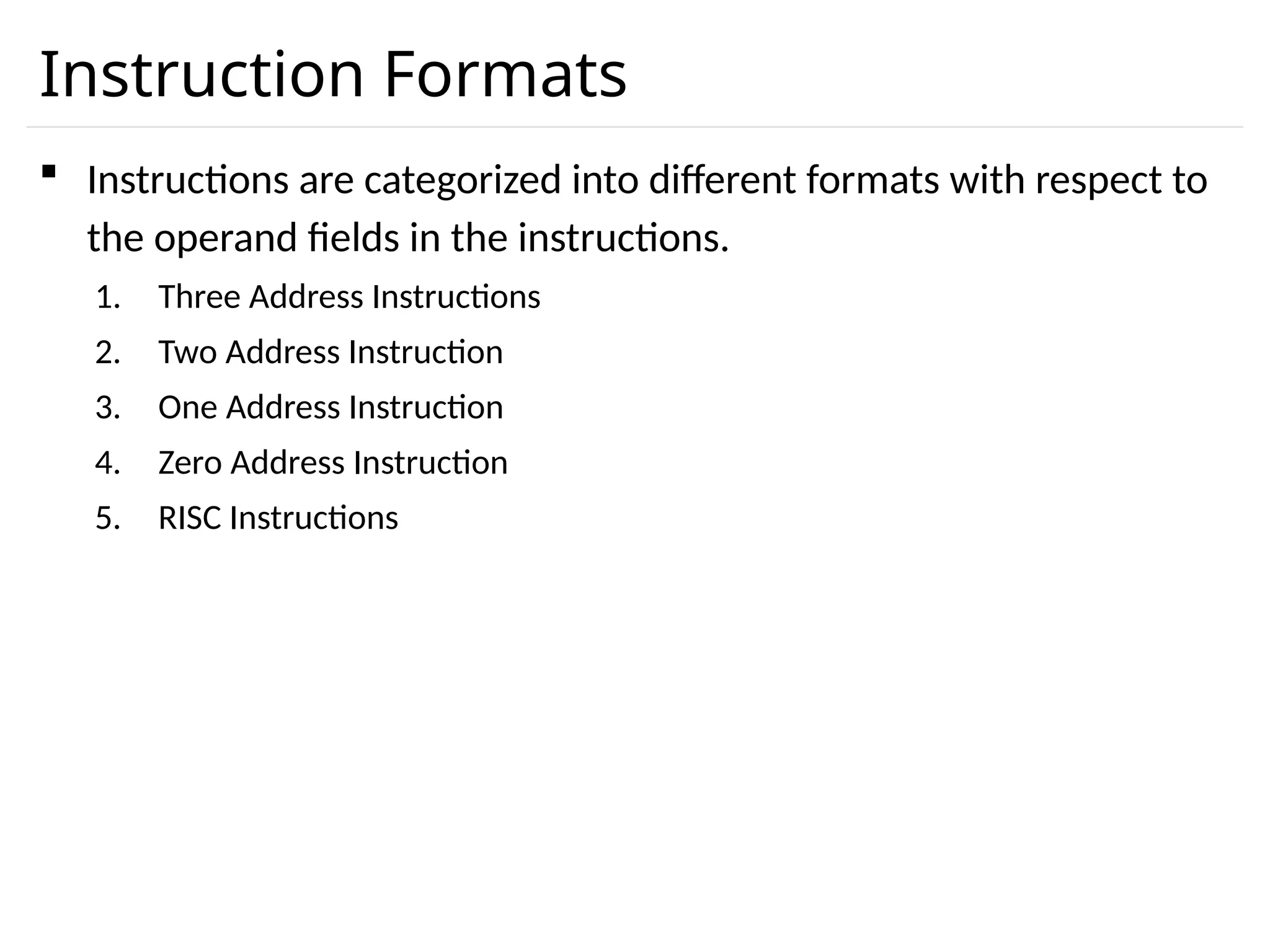
Instruction Formats Instructionsare categorized into different formats with respect to the operand fields in the instructions. 1. Three Address Instructions 2. Two Address Instruction 3. One Address Instruction 4. Zero Address Instruction 5. RISC Instructions
19.
Three Address Instruction Computers with three-address instruction formats can use each address field to specify either a processor register or a memory operand. The program in assembly language that evaluates X = (A + B) * (C + D) is shown below. The advantage of three-address format is that it results in short programs when evaluating arithmetic expressions. The disadvantage is that the binary-coded instructions require too many bits to specify three addresses. ADD R1, A, B R1← M[A]+ M[B] ADD R2, C, D R2← M[C]+ M[D] MUL X, R1, R2 M[X]← R1 * R2
20.
Two Address Instruction Two address instructions are the most common in commercial computers. Here again each address field can specify either a processor register or a memory word. The program to evaluate X = (A + B) * (C + D) is as follows: MOV R1, A R1← M[A] ADD R1, B R1← R1+ M[B] MOV R2, C R2← M[C] ADD R2, D R2← R2+ M[D] MUL R1, R2 R1← R1 * R2 M[X]← R1 MOV X, R1
21.
One Address Instruction One address instructions use an implied accumulator (AC) register for all data manipulation. For multiplication and division these is a need for a second register. However, here we will neglect the second register and assume that the AC contains the result of all operations. The program to evaluate X = (A + B) * (C + D) is LOAD A AC← M[A] ADD B AC← AC+M[B] STORE T M[T]←AC LOAD C AC← M[C] ADD D AC← AC+M[D] MUL T AC← AC*M[T] STORE X M[X]←AC
22.
Zero Address Instruction A stack-organized computer does not use an address field for the instructions ADD and MUL. The PUSH and POP instructions, however, need an address field to specify the operand that communicates with the stack. The program to evaluate X = (A + B) * (C + D) will be written for a stack-organized computer. To evaluate arithmetic expressions in a stack computer, it is necessary to convert the expression into reverse polish notation. PUSH A TOS← M[A] PUSH B TOS← M[B] ADD TOS←(A+B) PUSH C TOS← M[C] PUSH D TOS← M[D] ADD TOS←(C+D) MUL TOS←(C+D)*(A+B) POP X M[X] ← TOS
23.
RISC Instruction Theinstruction set of a typical RISC processor is restricted to the use of load and store instructions when communicating between memory and CPU. All other instructions are executed within the registers of the CPU without referring to memory. A program for a RISC type CPU consists of LOAD and STORE instructions that have one memory and one register address, and computational-type instructions that have three addresses with all three specifying processor registers. The following is a program to evaluate X = (A + B) * (C + D) LOAD R1, A R1← M[A] LOAD R2, B R2← M[B] LOAD R3, C R3← M[C] LOAD R4, D R4← M[D] ADD R1, R1, R2 R1← R1+R2 ADD R3, R3, R4 R3← R3+R4 MUL R1, R1, R3 R1← R1*R3 STORE X, R1 M[X] ← R1
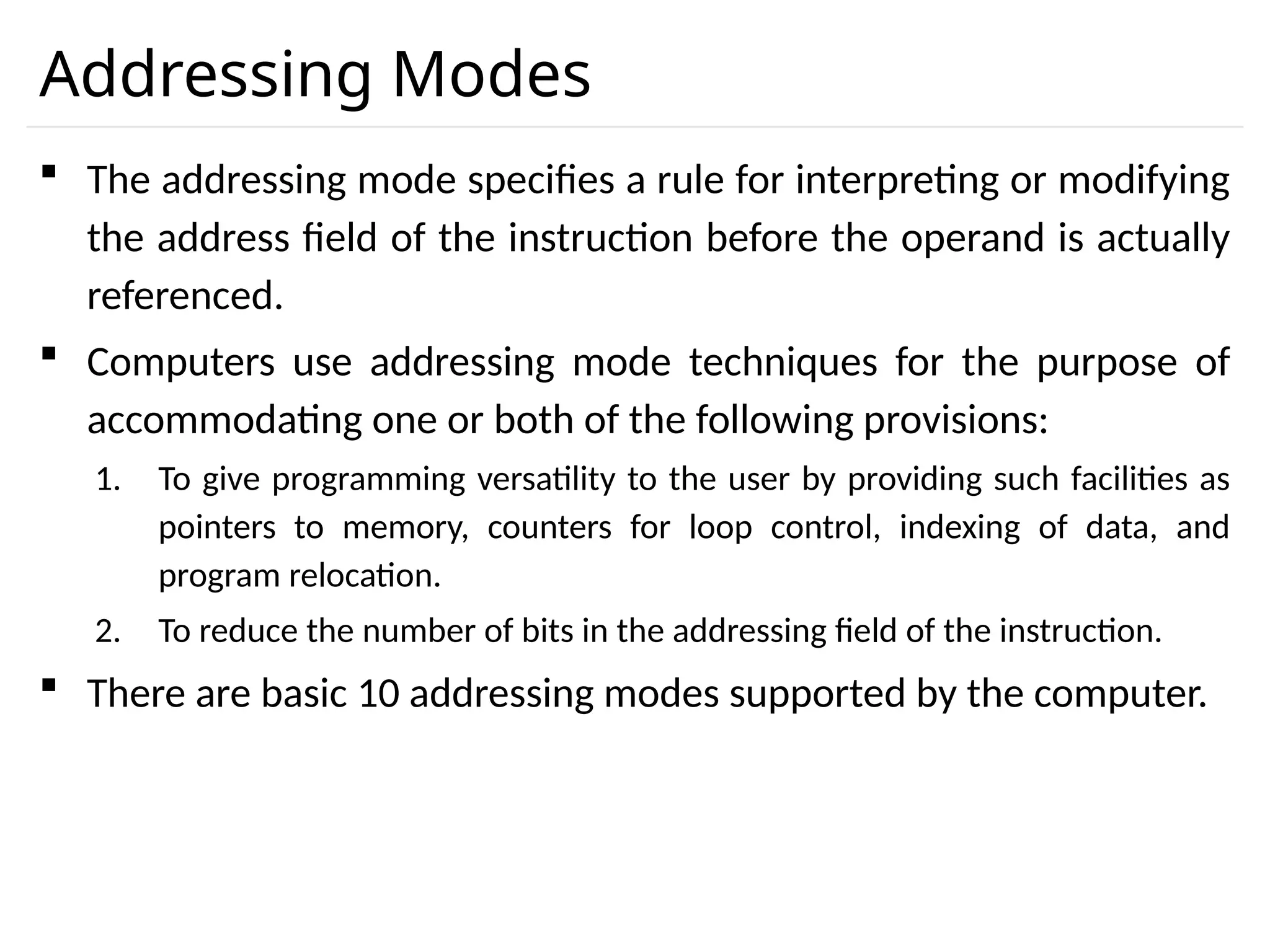
Addressing Modes Theaddressing mode specifies a rule for interpreting or modifying the address field of the instruction before the operand is actually referenced. Computers use addressing mode techniques for the purpose of accommodating one or both of the following provisions: 1. To give programming versatility to the user by providing such facilities as pointers to memory, counters for loop control, indexing of data, and program relocation. 2. To reduce the number of bits in the addressing field of the instruction. There are basic 10 addressing modes supported by the computer.
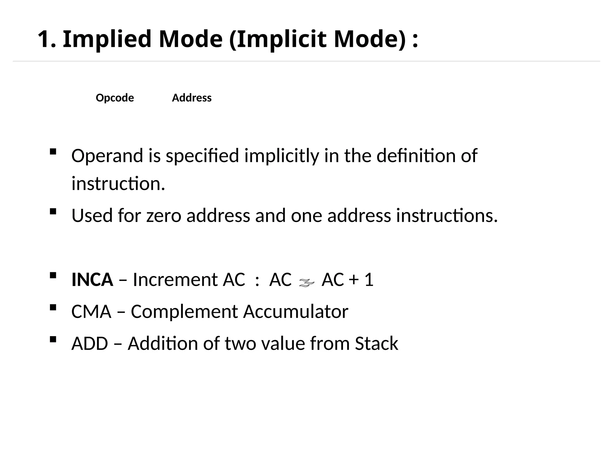
1. Implied Mode(Implicit Mode) : Operand is specified implicitly in the definition of instruction. Used for zero address and one address instructions. INCA – Increment AC : AC AC + 1 CMA – Complement Accumulator ADD – Addition of two value from Stack Opcode Address
28.
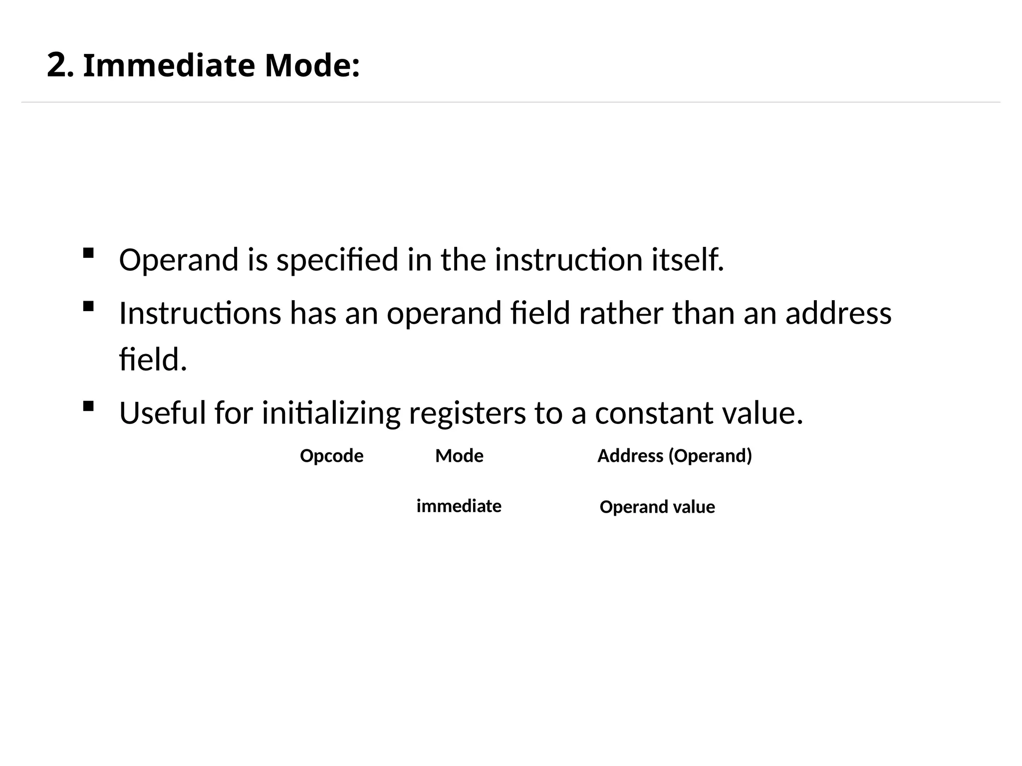
2. Immediate Mode: Operand is specified in the instruction itself. Instructions has an operand field rather than an address field. Useful for initializing registers to a constant value. Opcode Mode Address (Operand) immediate Operand value
29.
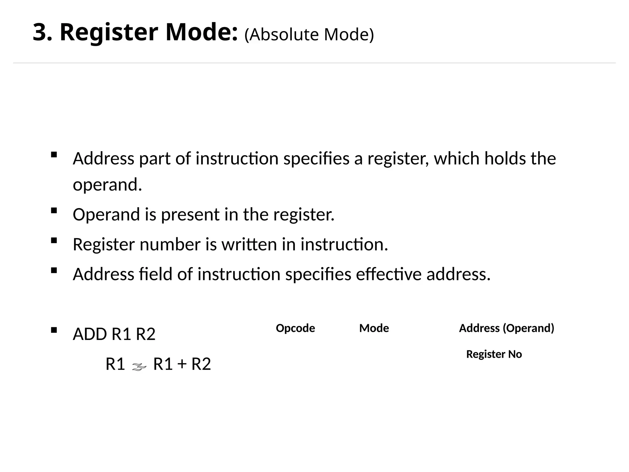
3. Register Mode:(Absolute Mode) Address part of instruction specifies a register, which holds the operand. Operand is present in the register. Register number is written in instruction. Address field of instruction specifies effective address. ADD R1 R2 R1 R1 + R2 Register No Opcode Mode Address (Operand)
30.
4. Register IndirectMode : • Register contains address of operand rather than operands itself. • Used to shorten the instruction length. ADD R1,(R2) : R1 R1 + M[(R2)]
31.
Assume a systemwith 4GB main memory & CPU has 64 general purpose registers. MM add = 32 bit Register references = 6 bit
32.
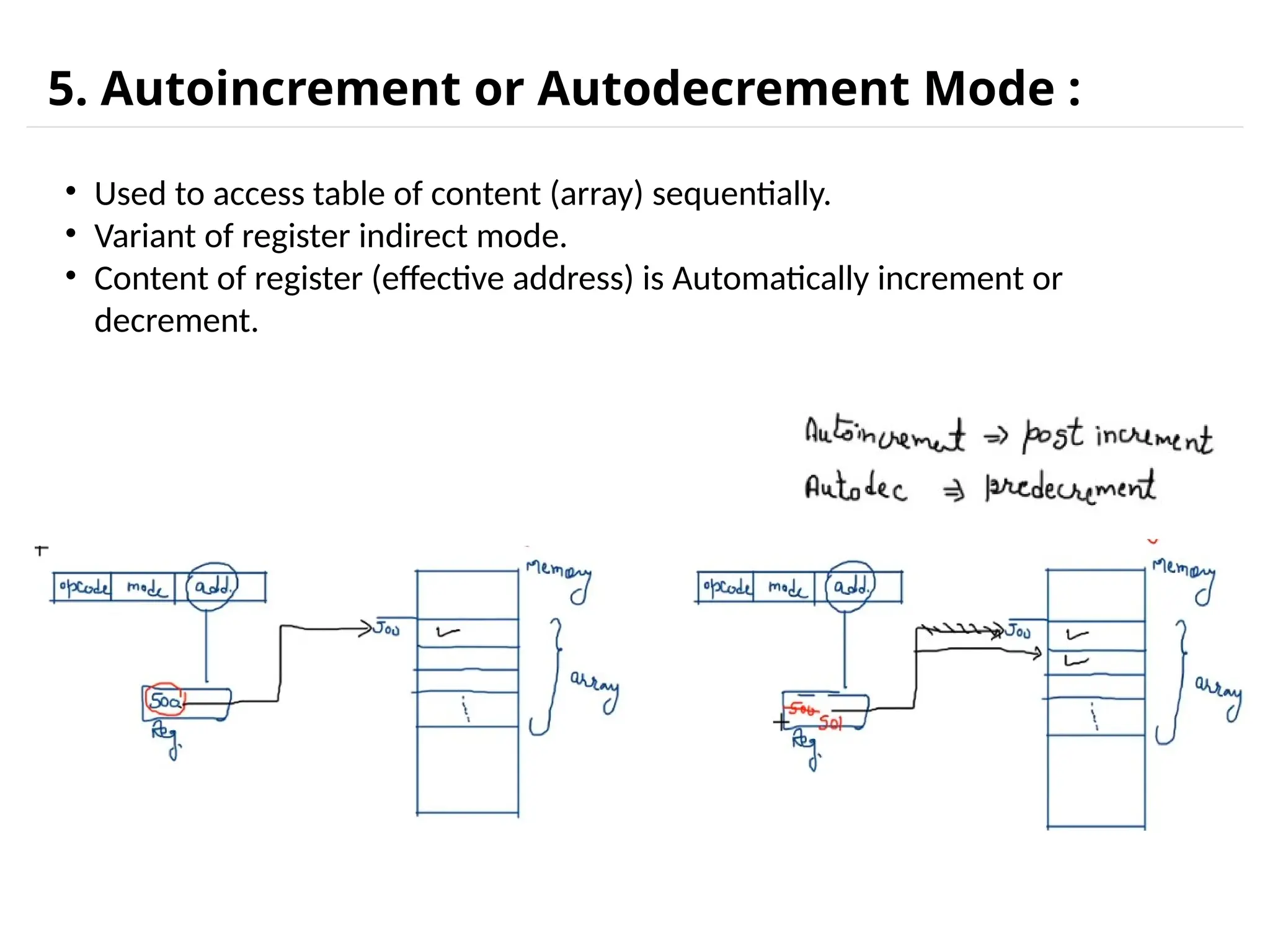
5. Autoincrement orAutodecrement Mode : • Used to access table of content (array) sequentially. • Variant of register indirect mode. • Content of register (effective address) is Automatically increment or decrement.
33.
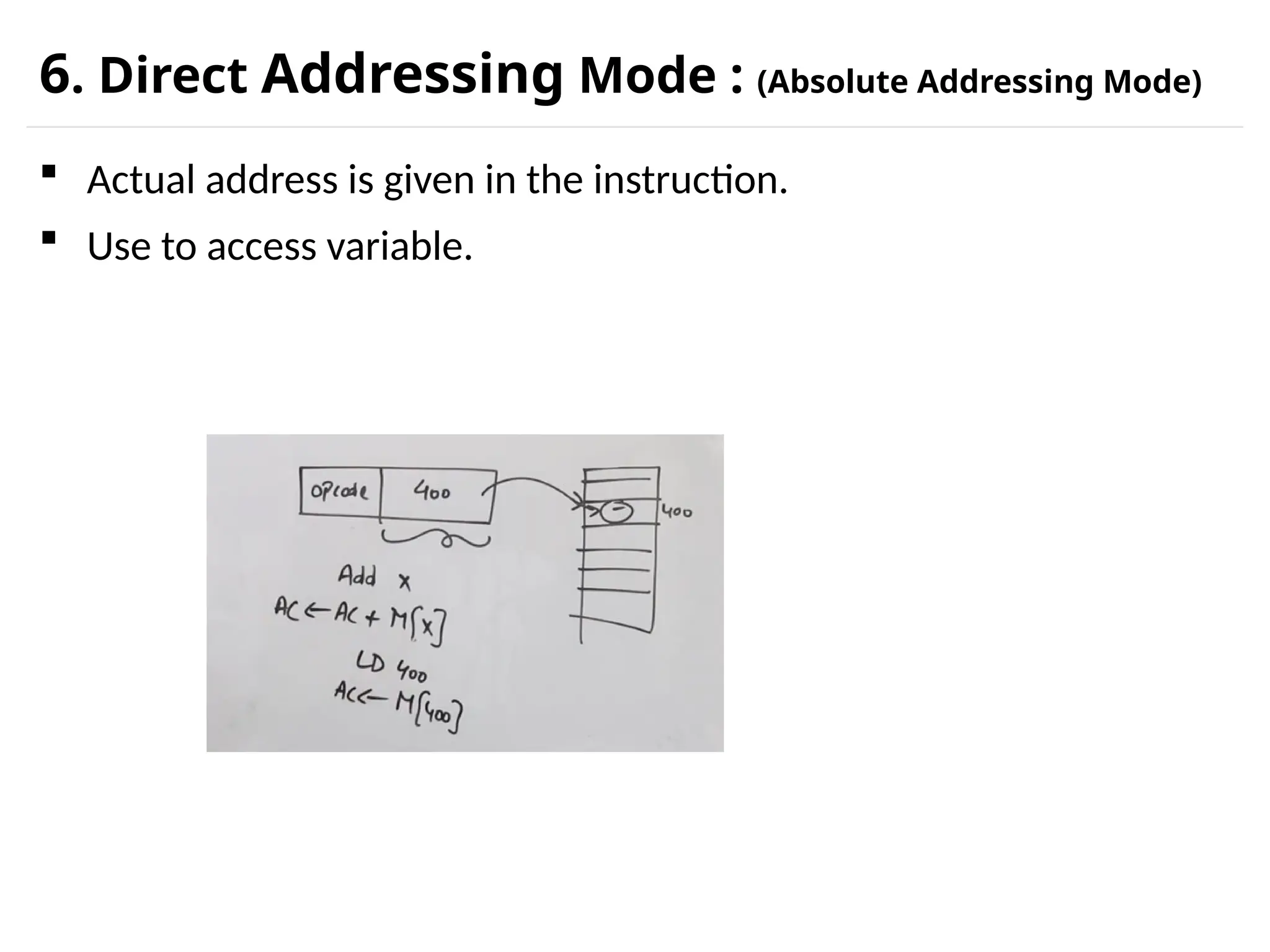
6. Direct AddressingMode : (Absolute Addressing Mode) Actual address is given in the instruction. Use to access variable.
34.
7. Indirect AddressingMode : Used to implement pointer and passing parameters. 2 memory access required. ADD X AC AC + M [ M[X] ] EA = 800 EA = M [x]
35.
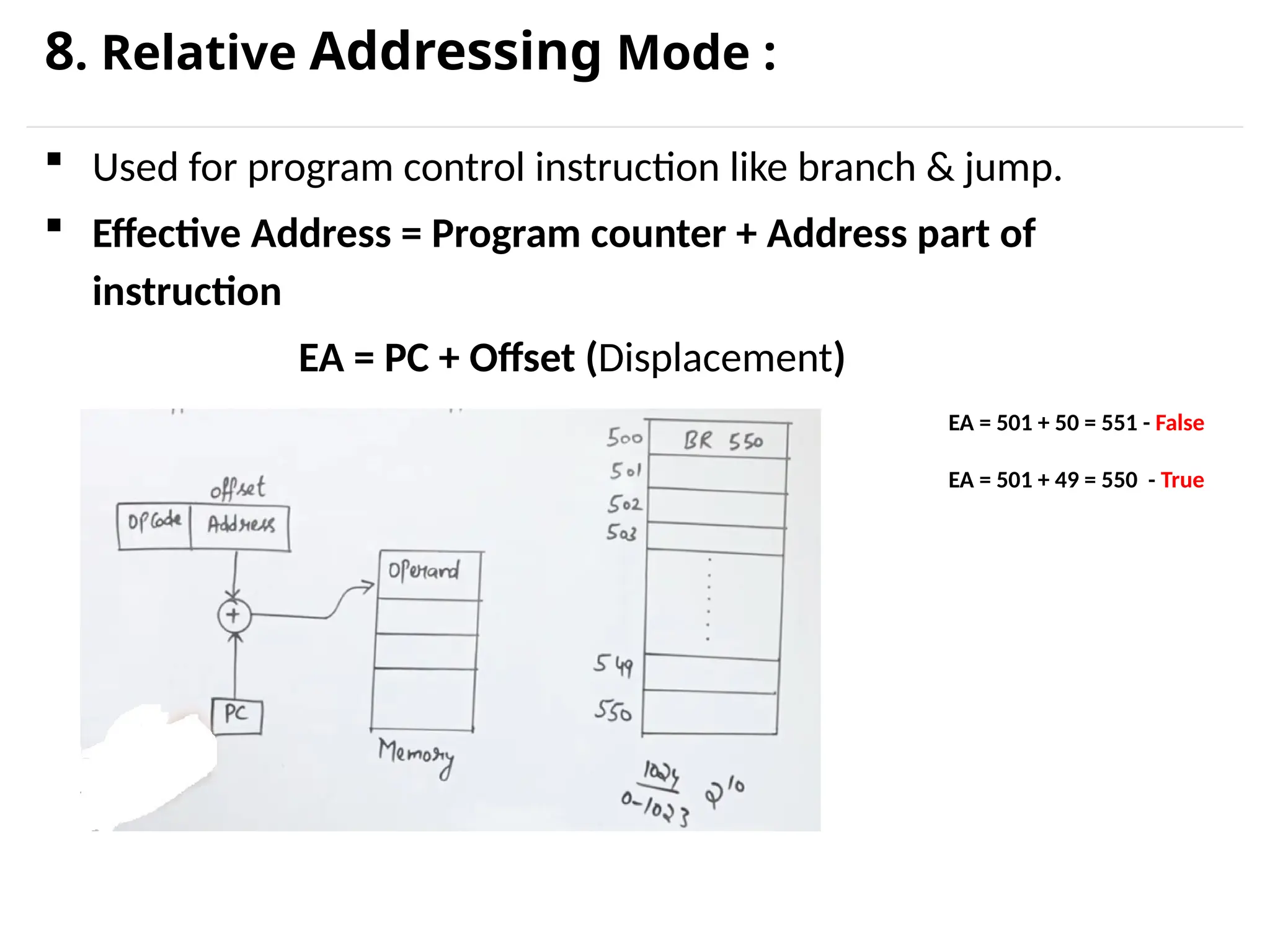
8. Relative AddressingMode : Used for program control instruction like branch & jump. Effective Address = Program counter + Address part of instruction EA = PC + Offset (Displacement) EA = 501 + 50 = 551 - False EA = 501 + 49 = 550 - True
36.
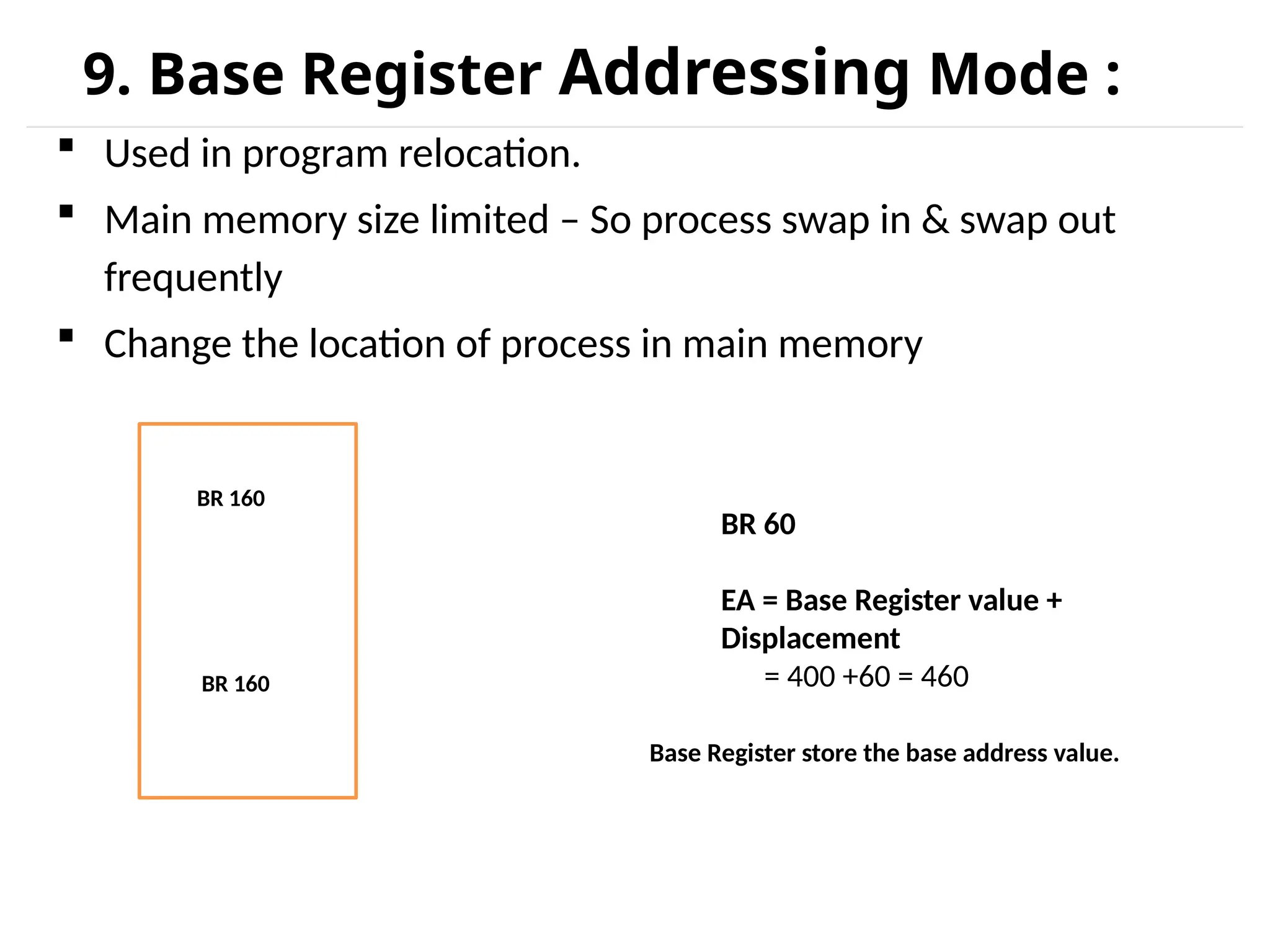
9. Base RegisterAddressing Mode : Used in program relocation. Main memory size limited – So process swap in & swap out frequently Change the location of process in main memory BR 160 BR 160 BR 60 EA = Base Register value + Displacement = 400 +60 = 460 Base Register store the base address value.
37.
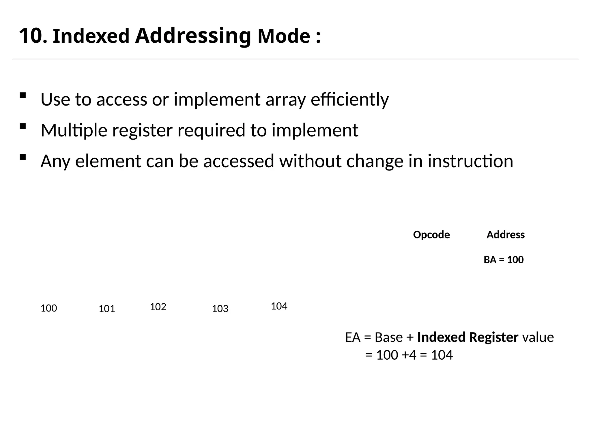
10. Indexed AddressingMode : Use to access or implement array efficiently Multiple register required to implement Any element can be accessed without change in instruction 100 101 102 103 104 EA = Base + Indexed Register value = 100 +4 = 104 Opcode Address BA = 100
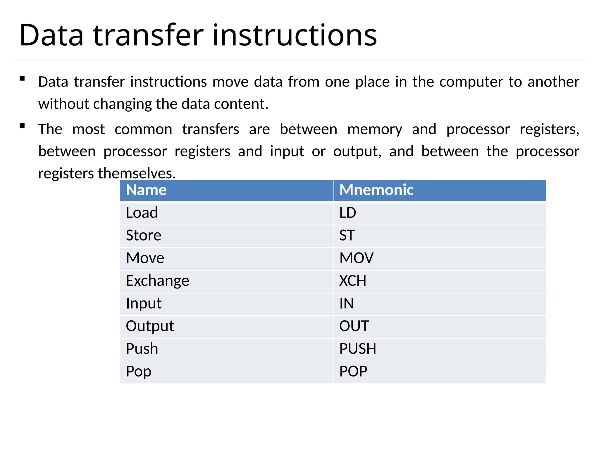
Data transfer instructions Data transfer instructions move data from one place in the computer to another without changing the data content. The most common transfers are between memory and processor registers, between processor registers and input or output, and between the processor registers themselves. Name Mnemonic Load LD Store ST Move MOV Exchange XCH Input IN Output OUT Push PUSH Pop POP
41.
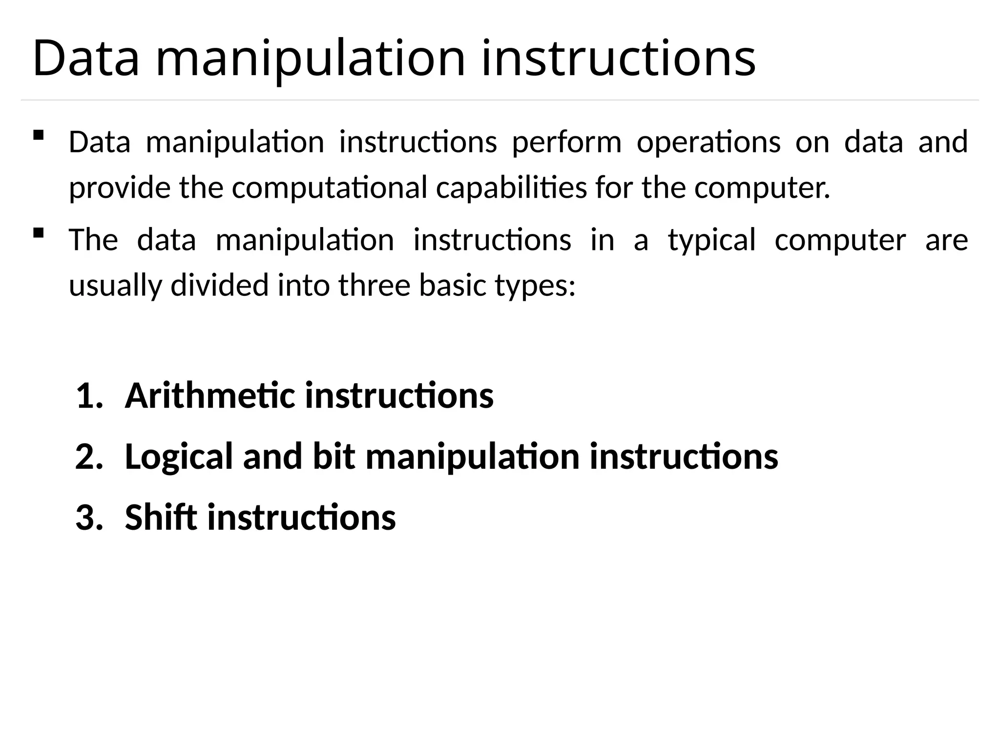
Data manipulation instructions Data manipulation instructions perform operations on data and provide the computational capabilities for the computer. The data manipulation instructions in a typical computer are usually divided into three basic types: 1. Arithmetic instructions 2. Logical and bit manipulation instructions 3. Shift instructions
42.
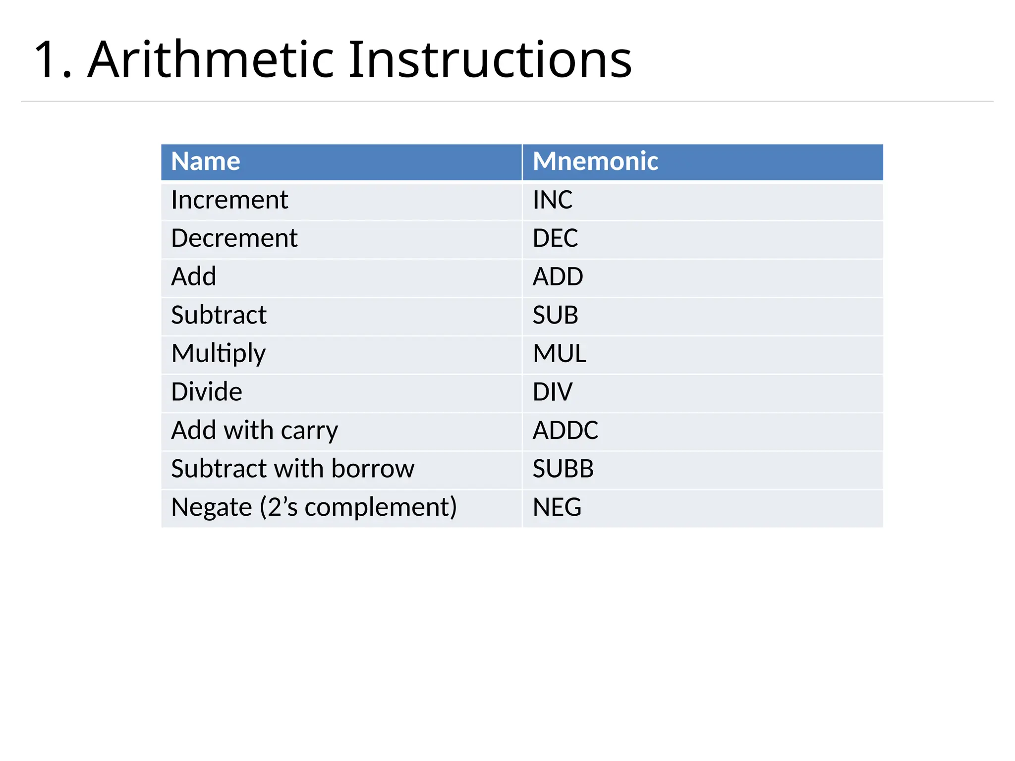
1. Arithmetic Instructions NameMnemonic Increment INC Decrement DEC Add ADD Subtract SUB Multiply MUL Divide DIV Add with carry ADDC Subtract with borrow SUBB Negate (2’s complement) NEG
43.
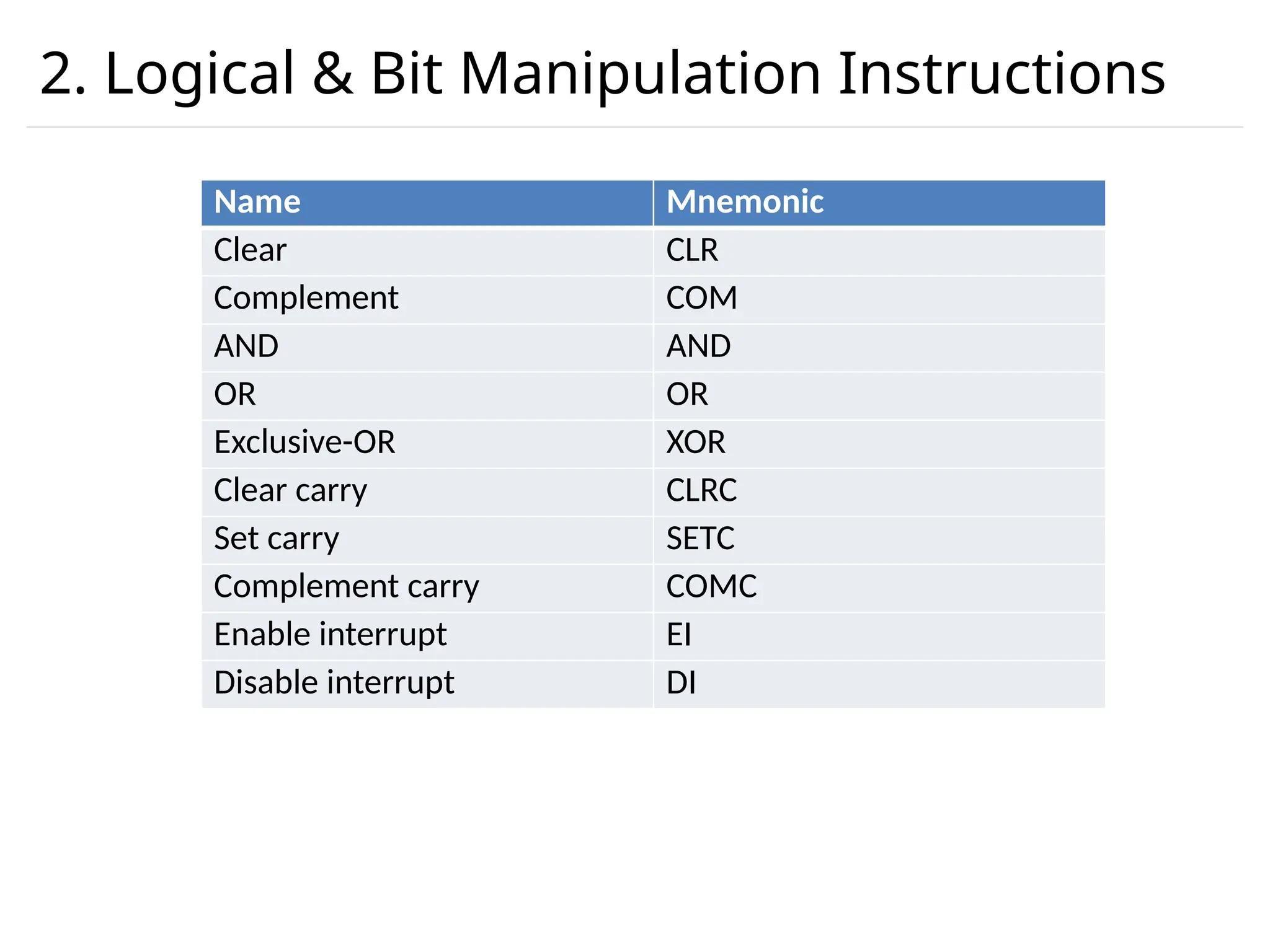
2. Logical &Bit Manipulation Instructions Name Mnemonic Clear CLR Complement COM AND AND OR OR Exclusive-OR XOR Clear carry CLRC Set carry SETC Complement carry COMC Enable interrupt EI Disable interrupt DI
44.
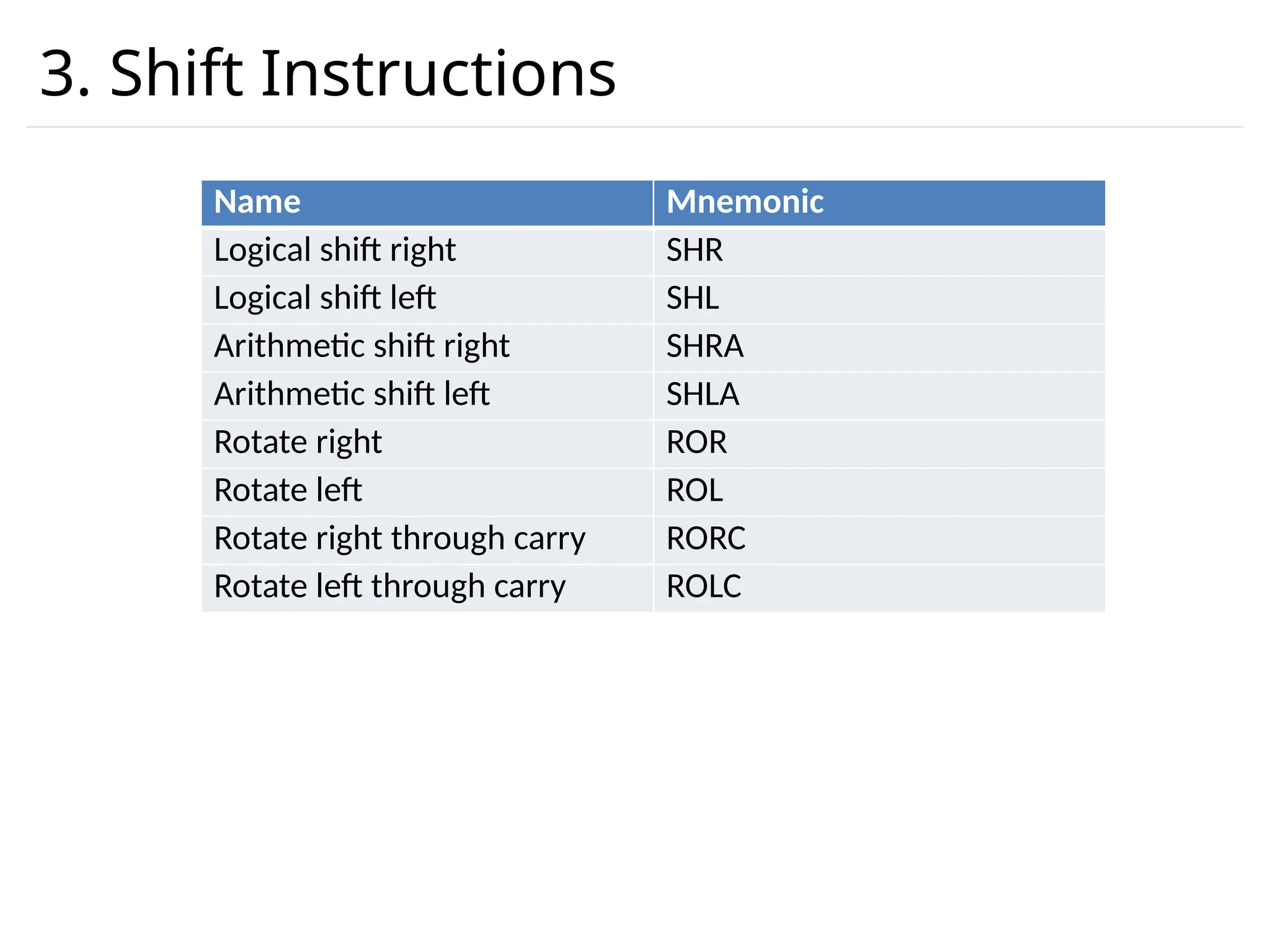
3. Shift Instructions NameMnemonic Logical shift right SHR Logical shift left SHL Arithmetic shift right SHRA Arithmetic shift left SHLA Rotate right ROR Rotate left ROL Rotate right through carry RORC Rotate left through carry ROLC
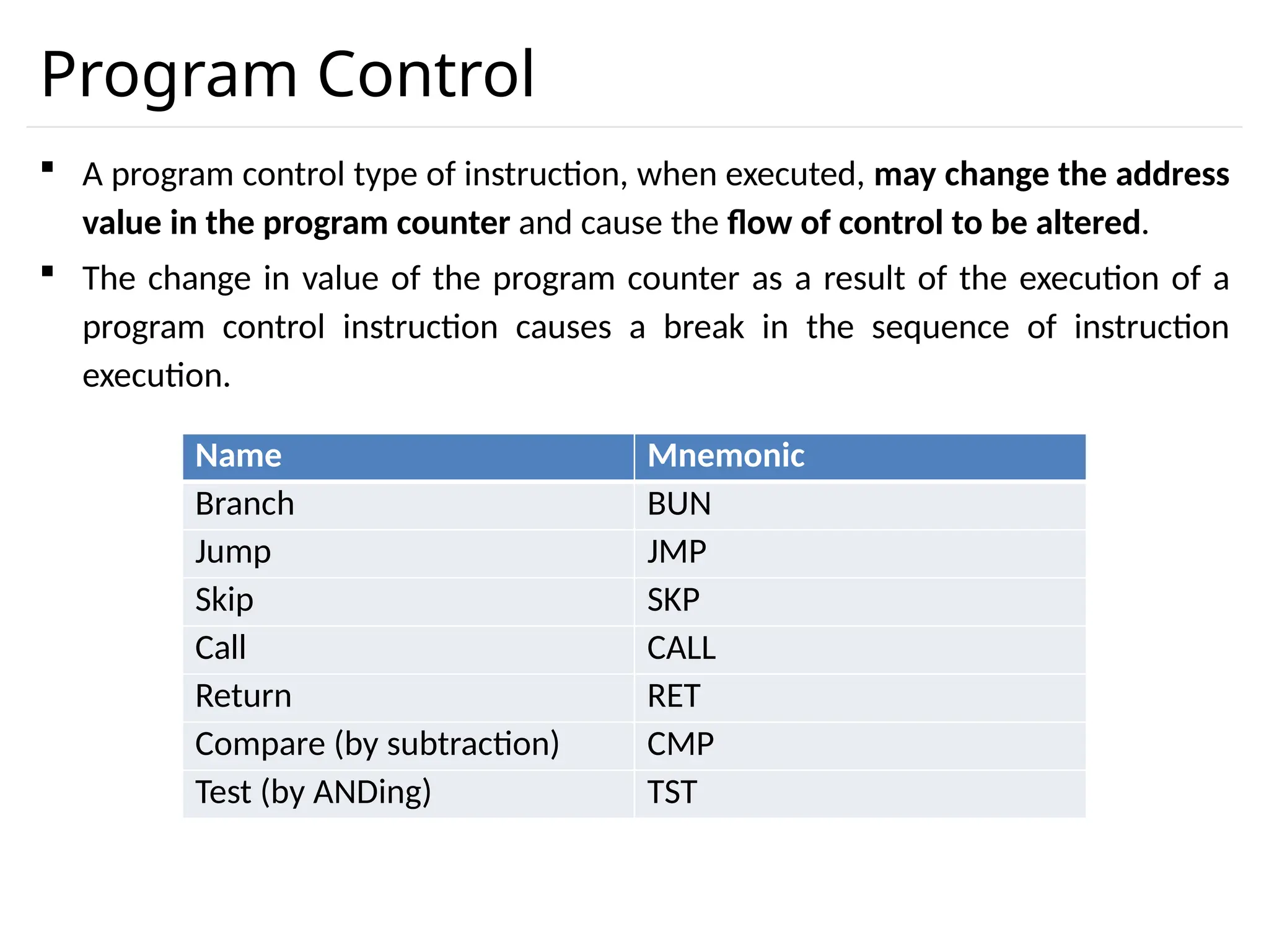
Program Control Aprogram control type of instruction, when executed, may change the address value in the program counter and cause the flow of control to be altered. The change in value of the program counter as a result of the execution of a program control instruction causes a break in the sequence of instruction execution. Name Mnemonic Branch BUN Jump JMP Skip SKP Call CALL Return RET Compare (by subtraction) CMP Test (by ANDing) TST
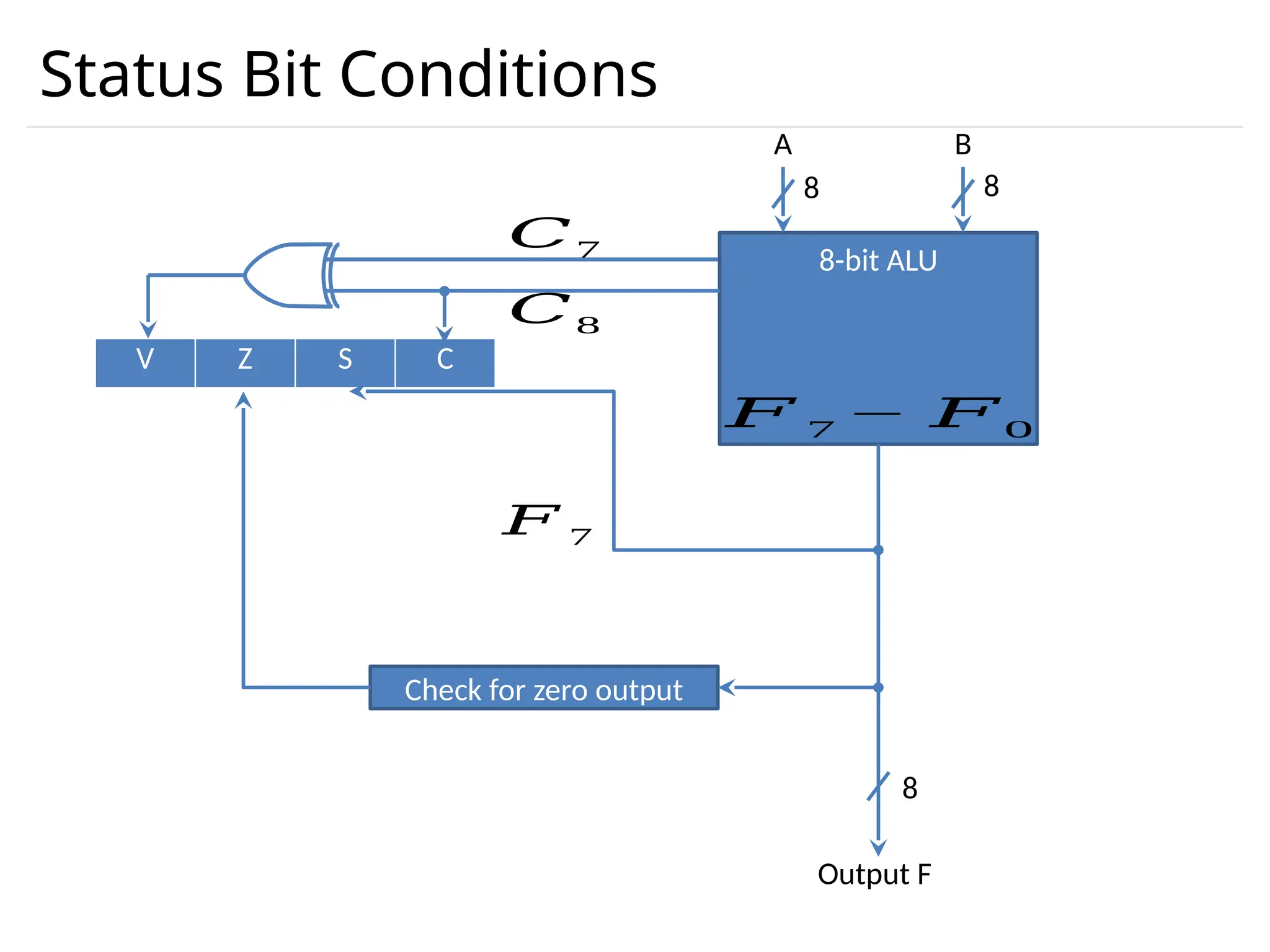
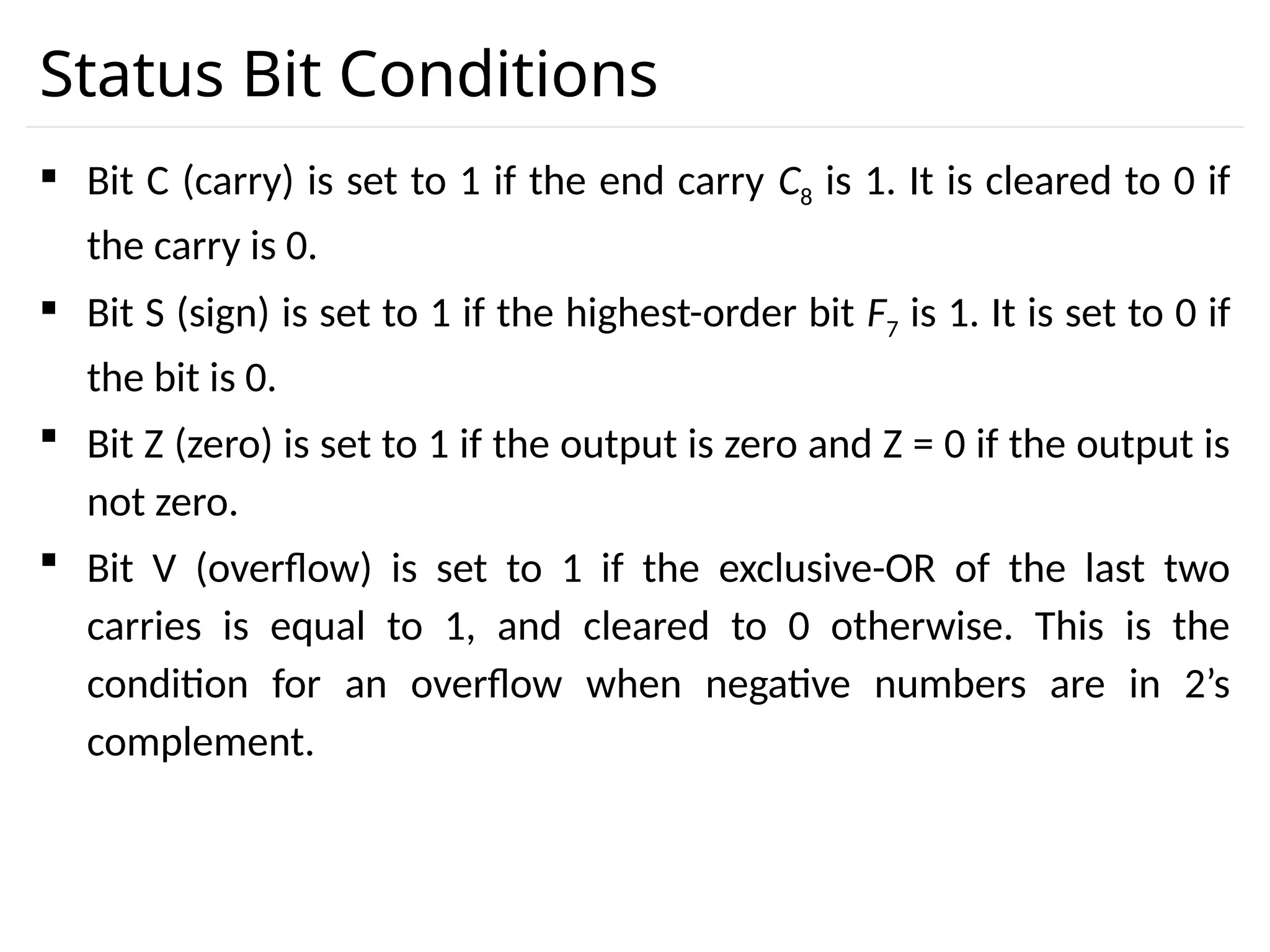
Status Bit Conditions Bit C (carry) is set to 1 if the end carry C8 is 1. It is cleared to 0 if the carry is 0. Bit S (sign) is set to 1 if the highest-order bit F7 is 1. It is set to 0 if the bit is 0. Bit Z (zero) is set to 1 if the output is zero and Z = 0 if the output is not zero. Bit V (overflow) is set to 1 if the exclusive-OR of the last two carries is equal to 1, and cleared to 0 otherwise. This is the condition for an overflow when negative numbers are in 2’s complement.
49.
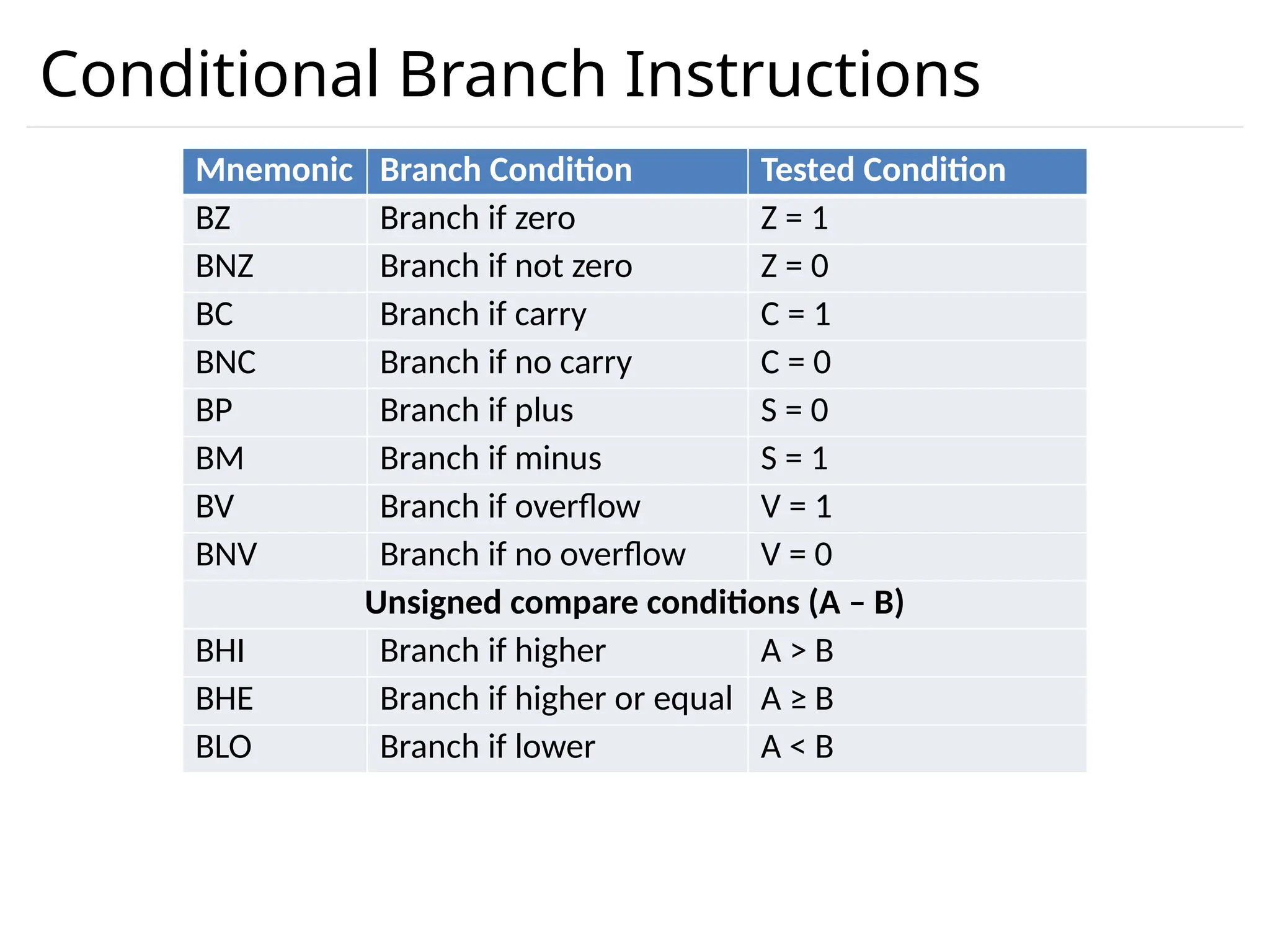
Conditional Branch Instructions MnemonicBranch Condition Tested Condition BZ Branch if zero Z = 1 BNZ Branch if not zero Z = 0 BC Branch if carry C = 1 BNC Branch if no carry C = 0 BP Branch if plus S = 0 BM Branch if minus S = 1 BV Branch if overflow V = 1 BNV Branch if no overflow V = 0 Unsigned compare conditions (A – B) BHI Branch if higher A > B BHE Branch if higher or equal A ≥ B BLO Branch if lower A < B
50.
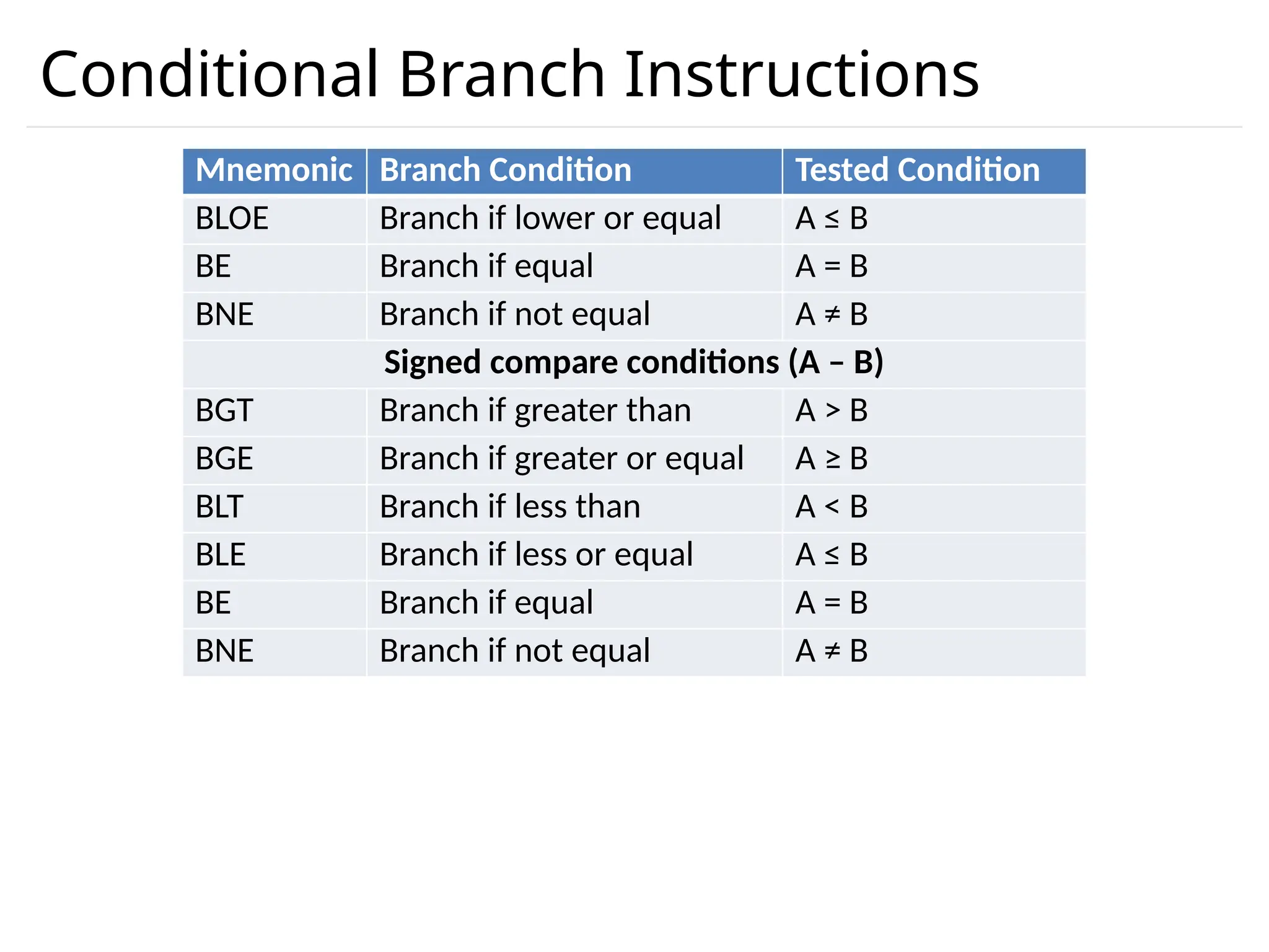
Conditional Branch Instructions MnemonicBranch Condition Tested Condition BLOE Branch if lower or equal A ≤ B BE Branch if equal A = B BNE Branch if not equal A ≠ B Signed compare conditions (A – B) BGT Branch if greater than A > B BGE Branch if greater or equal A ≥ B BLT Branch if less than A < B BLE Branch if less or equal A ≤ B BE Branch if equal A = B BNE Branch if not equal A ≠ B
51.
Program Interrupt Theinterrupt procedure is, in principle, quite similar to a subroutine call except for three variations: 1. The interrupt is usually initiated by an internal or external signal rather than from the execution of an instruction. 2. The address of the interrupt service program is determined by the hardware rather than from the address field of an instruction. 3. An interrupt procedure usually stores all the information necessary to define the state of the CPU rather than storing only the program counter. After a program has been interrupted and the service routine been executed, the CPU must return to exactly the same state that it was when the interrupt occurred. Only if this happens will the interrupted program be able to resume exactly as if nothing had happened.
52.
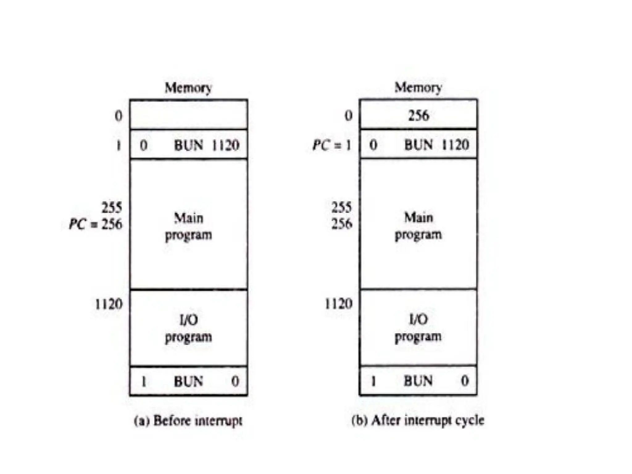
Program Interrupt Thestate of the CPU at the end of the execute cycle (when the interrupt is recognized) is determined from: 1. The content of the program counter 2. The content of all processor registers 3. The content of certain status conditions • The interrupt facility allows the running program to proceed until the input or output device sets its ready flag. Whenever a flag is set to 1, the computer completes the execution of the instruction in progress and then acknowledges the interrupt. The result of this action is that the return address is started in location 0. The instruction in location 1 is then performed; this initiates a service routine for the input or output transfer. The service routine can be stored in location 1.
54.
· The serviceroutine must have instructions to perform the following tasks: 1. Save contents of processor registers. 2. Check which flag is set. 3. Service the device whose flag is set. 4. Restore contents of processor registers. 5. Turn the interrupt facility on. 6. Return to the running program.
55.
Program Status Word(PSW) The collection of all status bit conditions in the CPU is sometimes called a program status word or PSW. The PSW is stored in a separate hardware register and contains the status information that characterizes the state of the CPU.
56.
Types of interrupts There are three major types of interrupts that cause a break in the normal execution of a program. They can be classified as: 1. External interrupts 2. Internal interrupts 3. Software interrupts
57.
1. External Interrupt External interrupts come from • Input-output (I/O) devices • Timing device • Circuit monitoring the power supply • Any other external source Examples that cause external interrupts are • I/O device requesting transfer of data • I/O device finished transfer of data • Elapsed time of an event • Power failure External interrupts are asynchronous. External interrupts depend on external conditions that are independent of the program being executed at the time.
58.
2. Internal interrupts(Traps) Internal interrupts arise from Illegal or erroneous use of an instruction or data. Internal interrupts are also called traps. Examples of interrupts caused by internal error conditions like • Register overflow • Attempt to divide by zero • invalid operation code • stack overflow • protection violation. These error conditions usually occur as a result of a premature termination of the instruction execution. Internal interrupts are synchronous with the program. If the program is rerun, the internal interrupts will occur in the same place each time.
59.
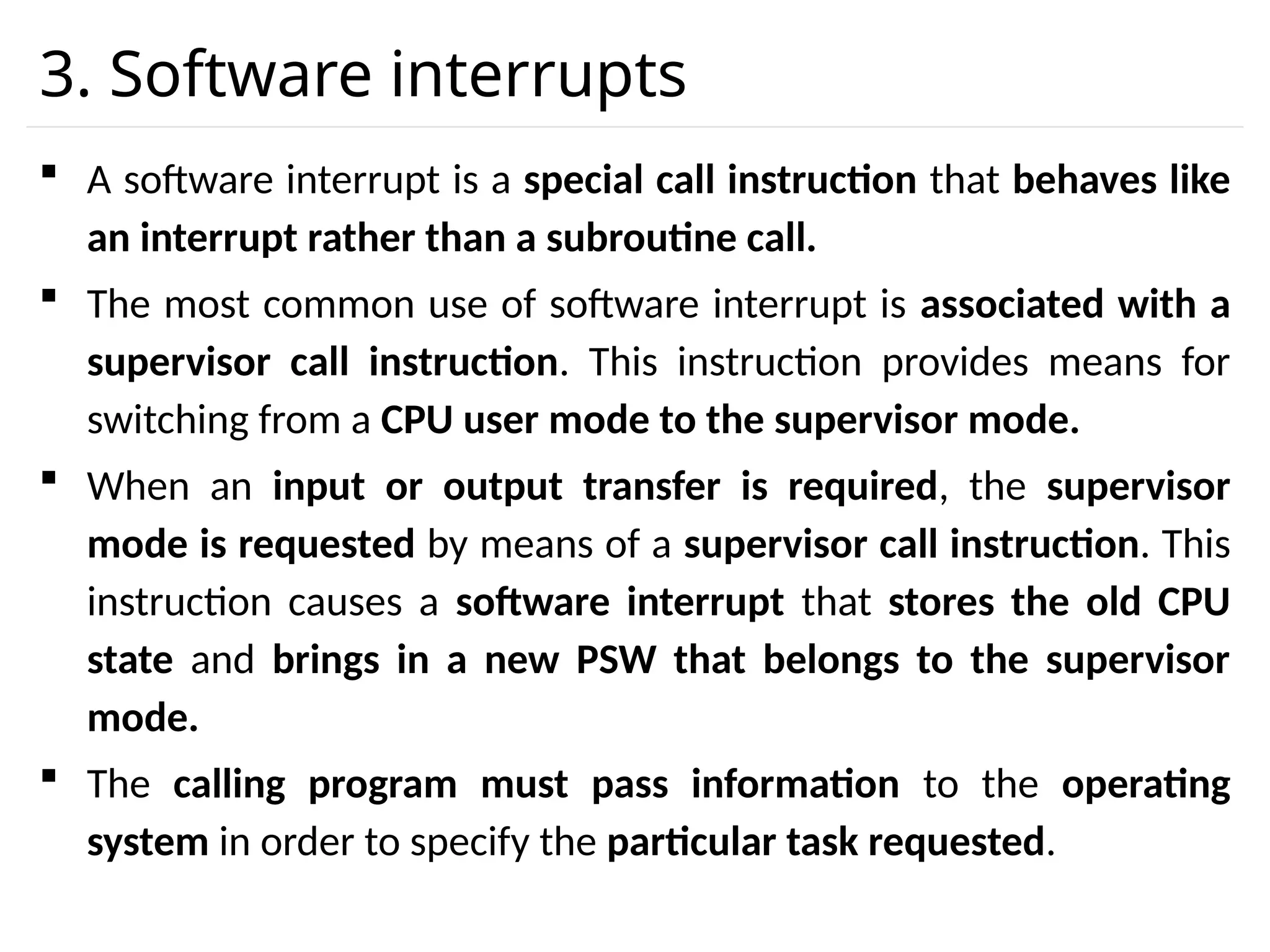
3. Software interrupts A software interrupt is a special call instruction that behaves like an interrupt rather than a subroutine call. The most common use of software interrupt is associated with a supervisor call instruction. This instruction provides means for switching from a CPU user mode to the supervisor mode. When an input or output transfer is required, the supervisor mode is requested by means of a supervisor call instruction. This instruction causes a software interrupt that stores the old CPU state and brings in a new PSW that belongs to the supervisor mode. The calling program must pass information to the operating system in order to specify the particular task requested.
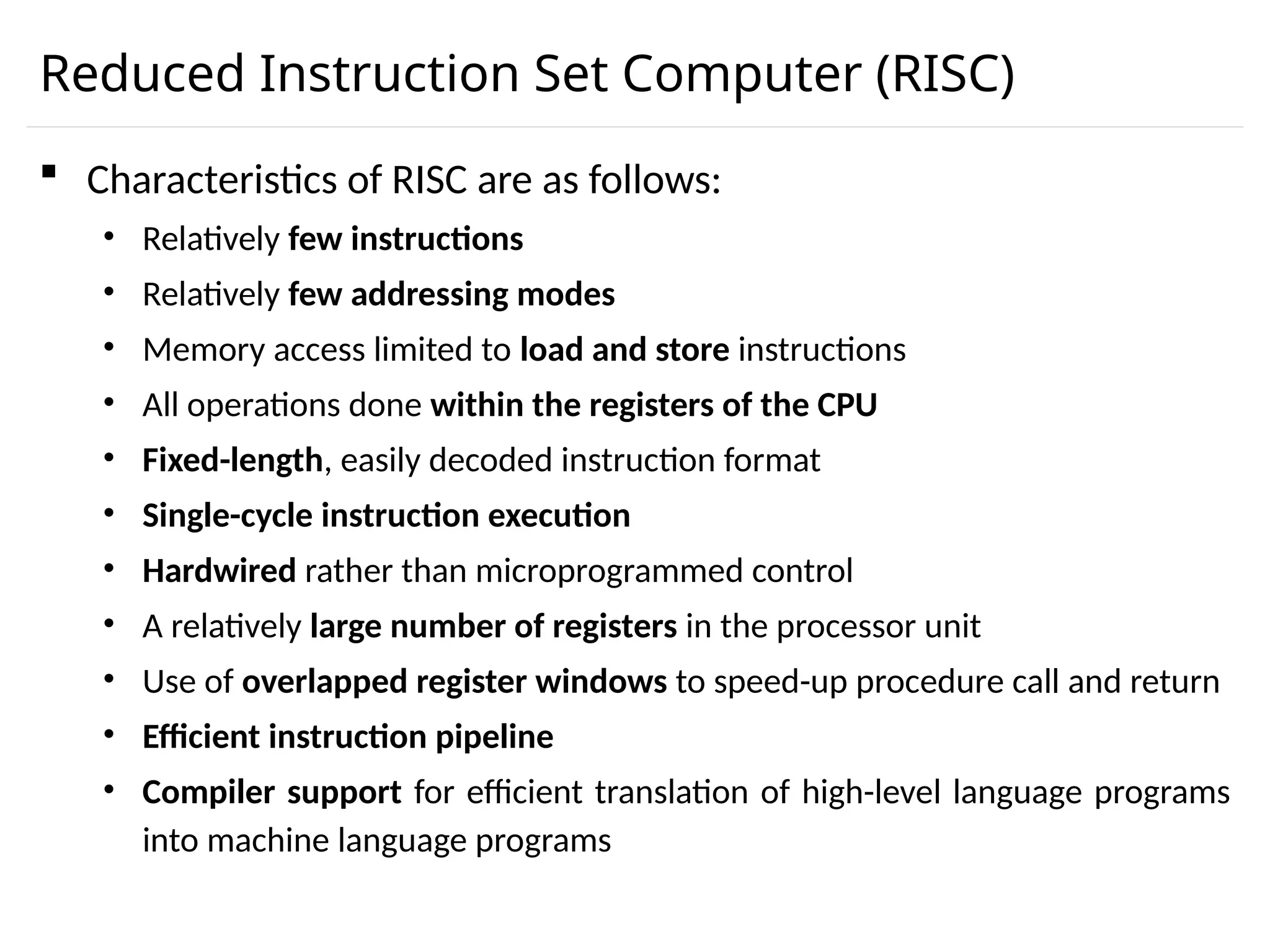
Reduced Instruction SetComputer (RISC) Characteristics of RISC are as follows: • Relatively few instructions • Relatively few addressing modes • Memory access limited to load and store instructions • All operations done within the registers of the CPU • Fixed-length, easily decoded instruction format • Single-cycle instruction execution • Hardwired rather than microprogrammed control • A relatively large number of registers in the processor unit • Use of overlapped register windows to speed-up procedure call and return • Efficient instruction pipeline • Compiler support for efficient translation of high-level language programs into machine language programs
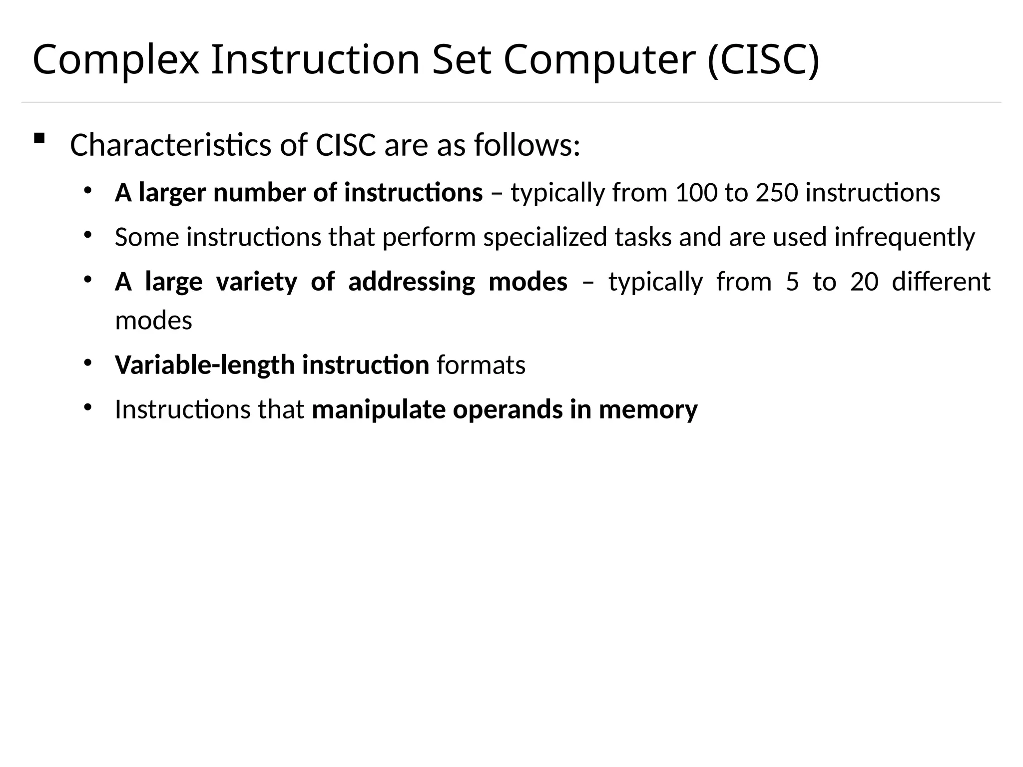
Complex Instruction SetComputer (CISC) Characteristics of CISC are as follows: • A larger number of instructions – typically from 100 to 250 instructions • Some instructions that perform specialized tasks and are used infrequently • A large variety of addressing modes – typically from 5 to 20 different modes • Variable-length instruction formats • Instructions that manipulate operands in memory
64.
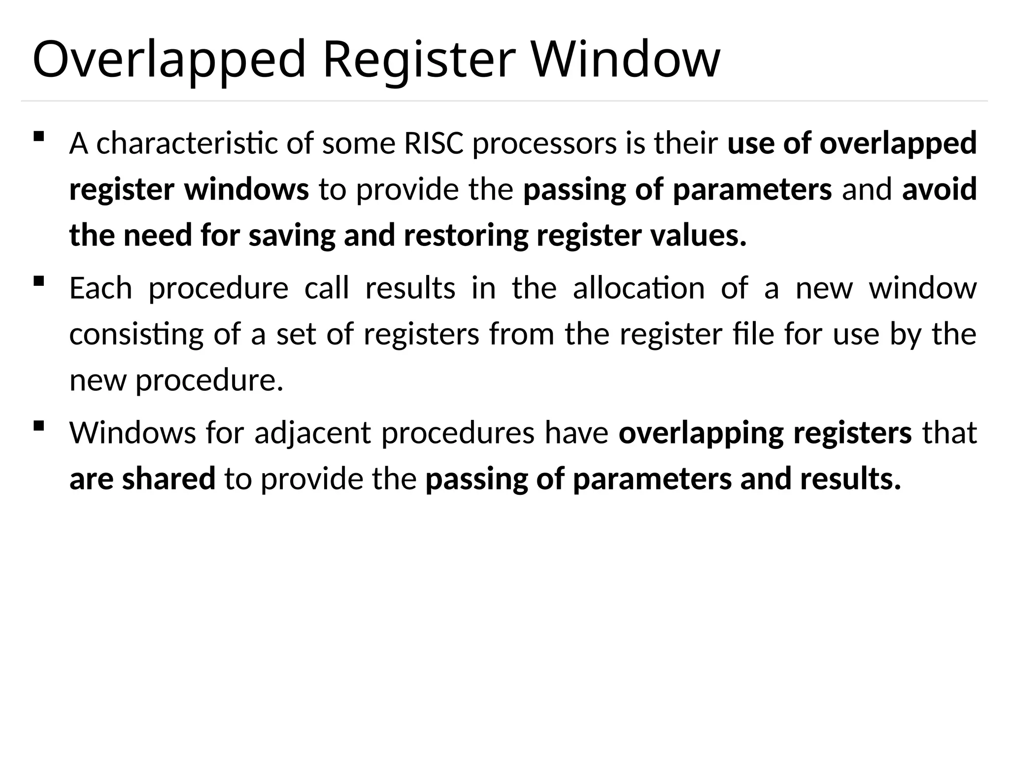
Overlapped Register Window A characteristic of some RISC processors is their use of overlapped register windows to provide the passing of parameters and avoid the need for saving and restoring register values. Each procedure call results in the allocation of a new window consisting of a set of registers from the register file for use by the new procedure. Windows for adjacent procedures have overlapping registers that are shared to provide the passing of parameters and results.
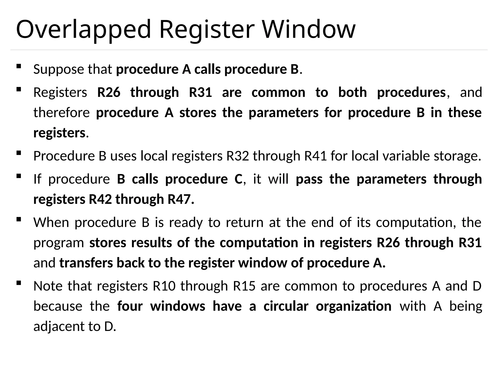
Overlapped Register Window Suppose that procedure A calls procedure B. Registers R26 through R31 are common to both procedures, and therefore procedure A stores the parameters for procedure B in these registers. Procedure B uses local registers R32 through R41 for local variable storage. If procedure B calls procedure C, it will pass the parameters through registers R42 through R47. When procedure B is ready to return at the end of its computation, the program stores results of the computation in registers R26 through R31 and transfers back to the register window of procedure A. Note that registers R10 through R15 are common to procedures A and D because the four windows have a circular organization with A being adjacent to D.
67.
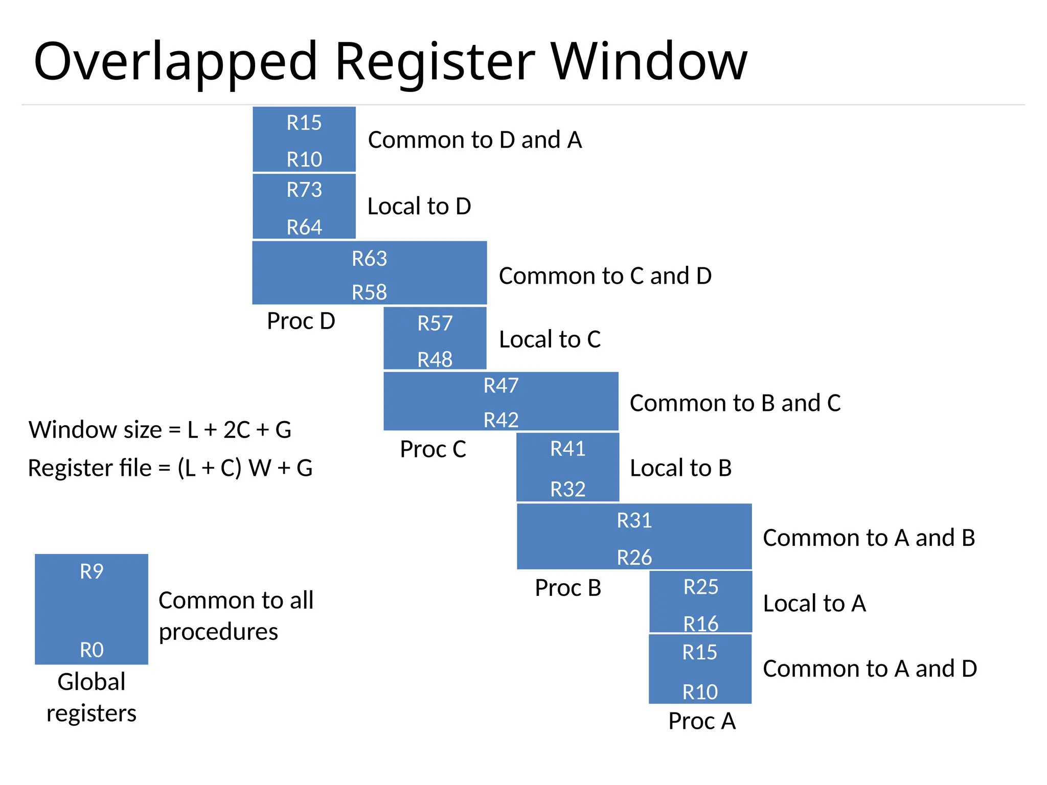
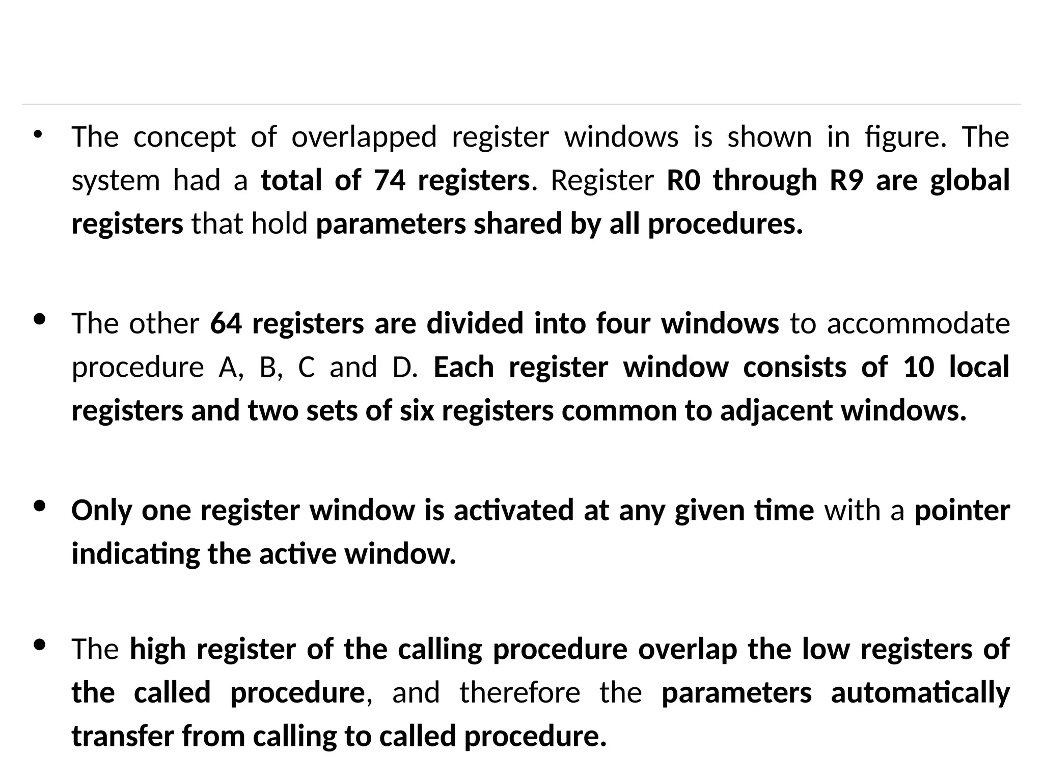
• The conceptof overlapped register windows is shown in figure. The system had a total of 74 registers. Register R0 through R9 are global registers that hold parameters shared by all procedures. · The other 64 registers are divided into four windows to accommodate procedure A, B, C and D. Each register window consists of 10 local registers and two sets of six registers common to adjacent windows. · Only one register window is activated at any given time with a pointer indicating the active window. · The high register of the calling procedure overlap the low registers of the called procedure, and therefore the parameters automatically transfer from calling to called procedure.
68.
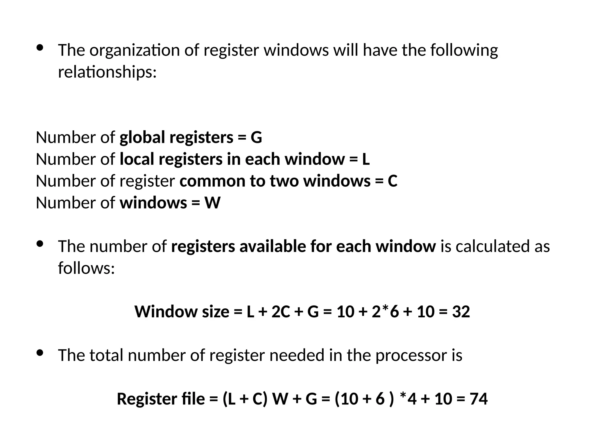
· The organizationof register windows will have the following relationships: Number of global registers = G Number of local registers in each window = L Number of register common to two windows = C Number of windows = W · The number of registers available for each window is calculated as follows: Window size = L + 2C + G = 10 + 2*6 + 10 = 32 · The total number of register needed in the processor is Register file = (L + C) W + G = (10 + 6 ) *4 + 10 = 74
69.
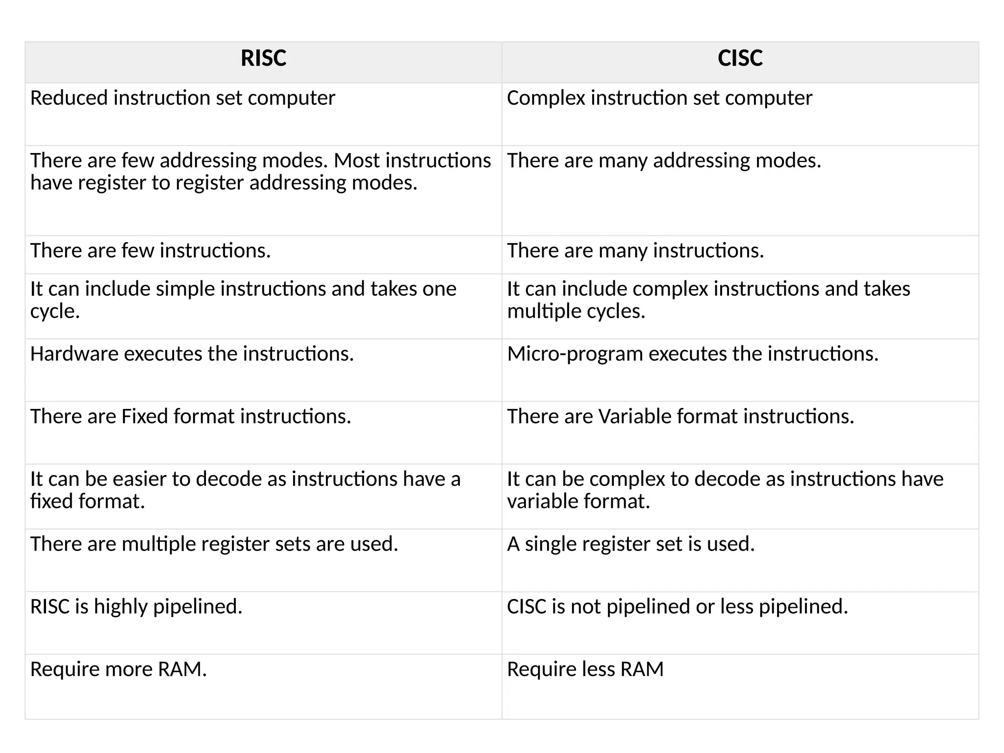
RISC CISC Reduced instructionset computer Complex instruction set computer There are few addressing modes. Most instructions have register to register addressing modes. There are many addressing modes. There are few instructions. There are many instructions. It can include simple instructions and takes one cycle. It can include complex instructions and takes multiple cycles. Hardware executes the instructions. Micro-program executes the instructions. There are Fixed format instructions. There are Variable format instructions. It can be easier to decode as instructions have a fixed format. It can be complex to decode as instructions have variable format. There are multiple register sets are used. A single register set is used. RISC is highly pipelined. CISC is not pipelined or less pipelined. Require more RAM. Require less RAM


![Register Stack PUSH Operation SP ← SP + 1 M[SP] ← DR IF (SP= 0) then (FULL ← 1) EMTY ← 0 POP Operation DR ← M[SP] SP ← SP - 1 IF (SP= 0) then (EMTY ← 1) FULL ← 0](https://image.slidesharecdn.com/unit-4cpuf-250326072427-c660a2b5/75/Central-processing-unit-pptx-for-computer-engineering-11-2048.jpg)
![Memory Stack PUSH Operation SP ← SP - 1 M[SP] ← DR POP Operation DR ← M[SP] SP ← SP + 1](https://image.slidesharecdn.com/unit-4cpuf-250326072427-c660a2b5/75/Central-processing-unit-pptx-for-computer-engineering-14-2048.jpg)

![Three Address Instruction Computers with three-address instruction formats can use each address field to specify either a processor register or a memory operand. The program in assembly language that evaluates X = (A + B) * (C + D) is shown below. The advantage of three-address format is that it results in short programs when evaluating arithmetic expressions. The disadvantage is that the binary-coded instructions require too many bits to specify three addresses. ADD R1, A, B R1← M[A]+ M[B] ADD R2, C, D R2← M[C]+ M[D] MUL X, R1, R2 M[X]← R1 * R2](https://image.slidesharecdn.com/unit-4cpuf-250326072427-c660a2b5/75/Central-processing-unit-pptx-for-computer-engineering-19-2048.jpg)
![Two Address Instruction Two address instructions are the most common in commercial computers. Here again each address field can specify either a processor register or a memory word. The program to evaluate X = (A + B) * (C + D) is as follows: MOV R1, A R1← M[A] ADD R1, B R1← R1+ M[B] MOV R2, C R2← M[C] ADD R2, D R2← R2+ M[D] MUL R1, R2 R1← R1 * R2 M[X]← R1 MOV X, R1](https://image.slidesharecdn.com/unit-4cpuf-250326072427-c660a2b5/75/Central-processing-unit-pptx-for-computer-engineering-20-2048.jpg)
![One Address Instruction One address instructions use an implied accumulator (AC) register for all data manipulation. For multiplication and division these is a need for a second register. However, here we will neglect the second register and assume that the AC contains the result of all operations. The program to evaluate X = (A + B) * (C + D) is LOAD A AC← M[A] ADD B AC← AC+M[B] STORE T M[T]←AC LOAD C AC← M[C] ADD D AC← AC+M[D] MUL T AC← AC*M[T] STORE X M[X]←AC](https://image.slidesharecdn.com/unit-4cpuf-250326072427-c660a2b5/75/Central-processing-unit-pptx-for-computer-engineering-21-2048.jpg)
![Zero Address Instruction A stack-organized computer does not use an address field for the instructions ADD and MUL. The PUSH and POP instructions, however, need an address field to specify the operand that communicates with the stack. The program to evaluate X = (A + B) * (C + D) will be written for a stack-organized computer. To evaluate arithmetic expressions in a stack computer, it is necessary to convert the expression into reverse polish notation. PUSH A TOS← M[A] PUSH B TOS← M[B] ADD TOS←(A+B) PUSH C TOS← M[C] PUSH D TOS← M[D] ADD TOS←(C+D) MUL TOS←(C+D)*(A+B) POP X M[X] ← TOS](https://image.slidesharecdn.com/unit-4cpuf-250326072427-c660a2b5/75/Central-processing-unit-pptx-for-computer-engineering-22-2048.jpg)
![RISC Instruction The instruction set of a typical RISC processor is restricted to the use of load and store instructions when communicating between memory and CPU. All other instructions are executed within the registers of the CPU without referring to memory. A program for a RISC type CPU consists of LOAD and STORE instructions that have one memory and one register address, and computational-type instructions that have three addresses with all three specifying processor registers. The following is a program to evaluate X = (A + B) * (C + D) LOAD R1, A R1← M[A] LOAD R2, B R2← M[B] LOAD R3, C R3← M[C] LOAD R4, D R4← M[D] ADD R1, R1, R2 R1← R1+R2 ADD R3, R3, R4 R3← R3+R4 MUL R1, R1, R3 R1← R1*R3 STORE X, R1 M[X] ← R1](https://image.slidesharecdn.com/unit-4cpuf-250326072427-c660a2b5/75/Central-processing-unit-pptx-for-computer-engineering-23-2048.jpg)

![4. Register Indirect Mode : • Register contains address of operand rather than operands itself. • Used to shorten the instruction length. ADD R1,(R2) : R1 R1 + M[(R2)]](https://image.slidesharecdn.com/unit-4cpuf-250326072427-c660a2b5/75/Central-processing-unit-pptx-for-computer-engineering-30-2048.jpg)

![7. Indirect Addressing Mode : Used to implement pointer and passing parameters. 2 memory access required. ADD X AC AC + M [ M[X] ] EA = 800 EA = M [x]](https://image.slidesharecdn.com/unit-4cpuf-250326072427-c660a2b5/75/Central-processing-unit-pptx-for-computer-engineering-34-2048.jpg)