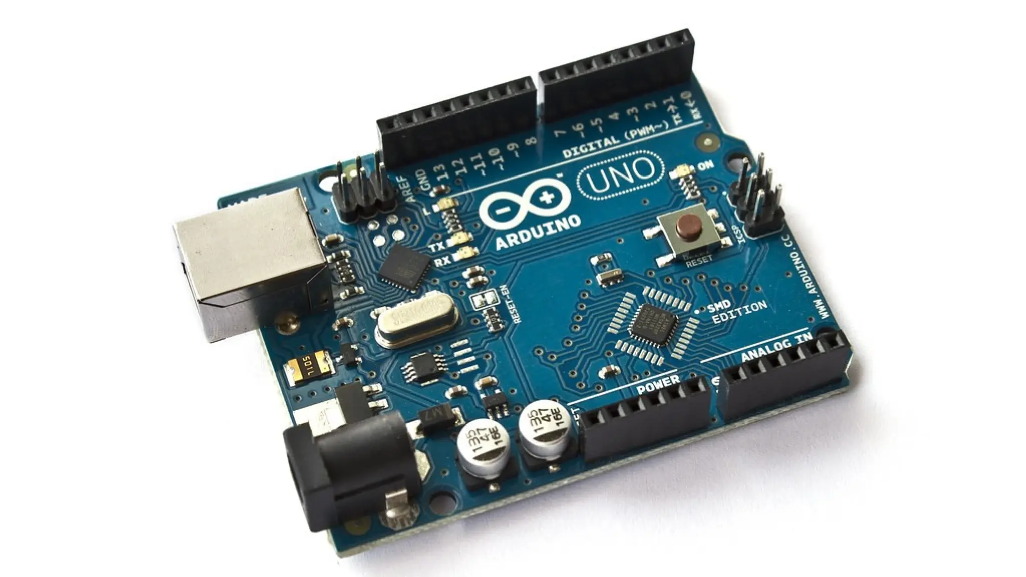
What is ArduinoUno? It is a microcontroller board that makes it easy to learn about electronics and programming.
4.
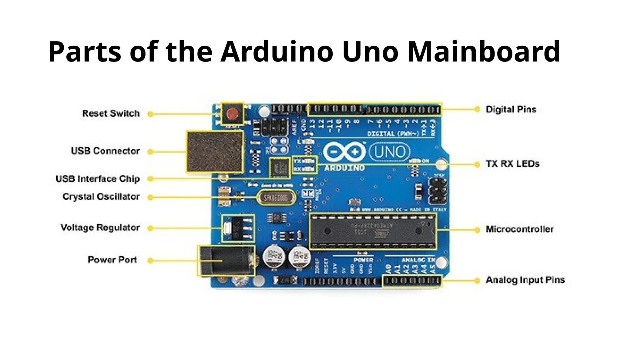
Main Parts ofthe Mainboard Power supply components: To provide power to the microcontroller. Connectors: To connect to your computer and other devices. Input/output pins: To interact with the outside world (sensors, LEDs, motors, etc.). Supporting circuitry: Like a clock signal and reset button.
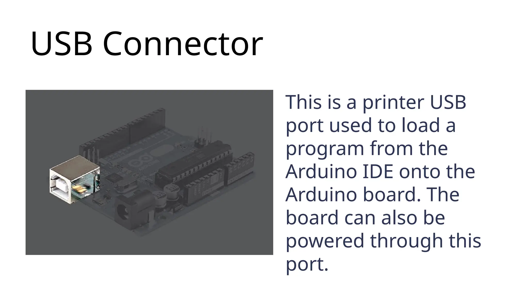
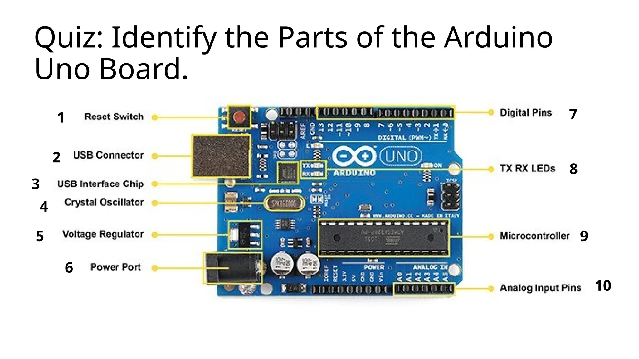
USB Connector This isa printer USB port used to load a program from the Arduino IDE onto the Arduino board. The board can also be powered through this port.
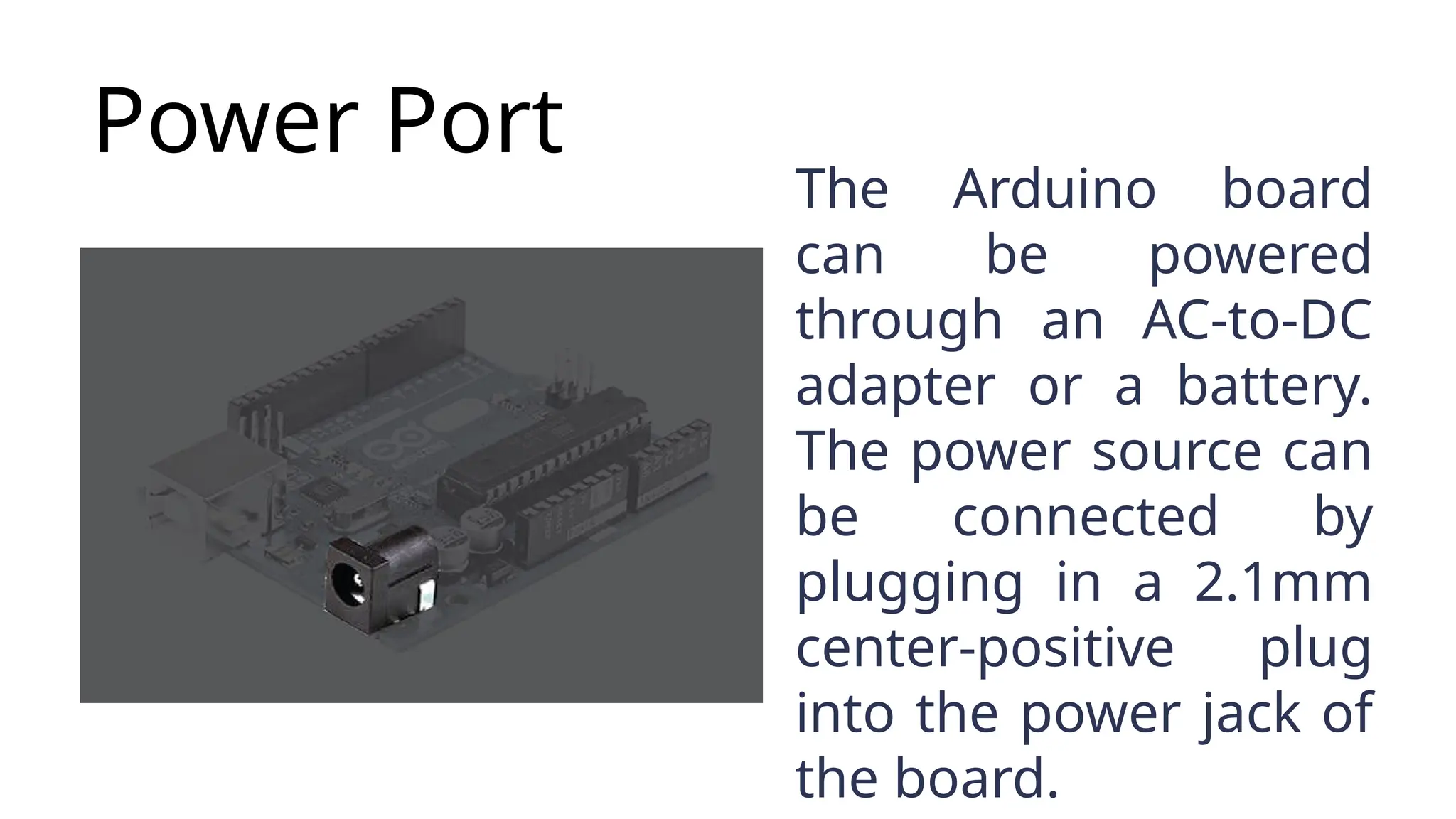
Power Port The Arduinoboard can be powered through an AC-to-DC adapter or a battery. The power source can be connected by plugging in a 2.1mm center-positive plug into the power jack of the board.
9.
Plug The Arduino UNOboard operates at a voltage of 5 volts, but it can withstand a maximum voltage of 20 volts.
10.
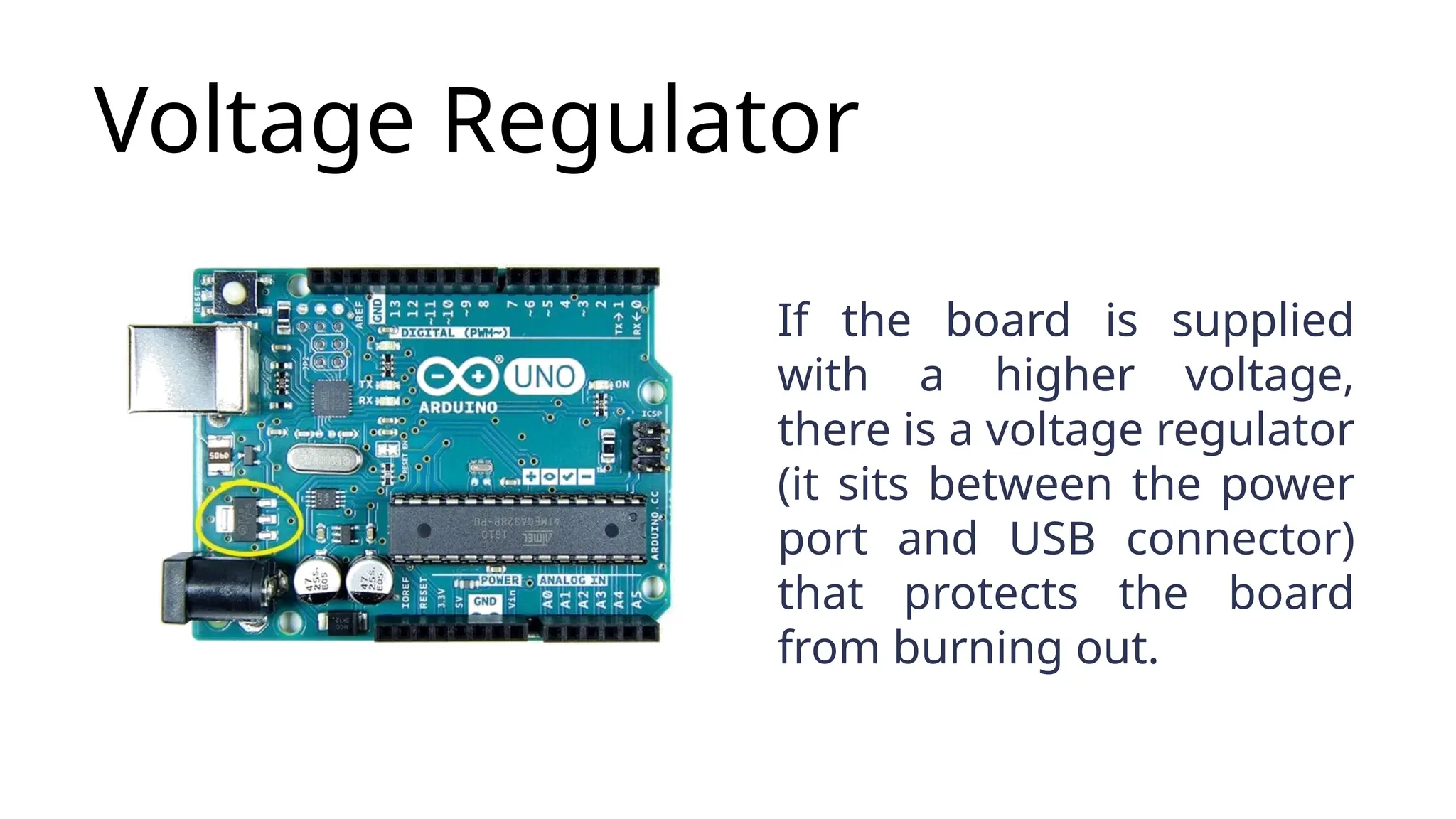
Voltage Regulator If theboard is supplied with a higher voltage, there is a voltage regulator (it sits between the power port and USB connector) that protects the board from burning out.
11.
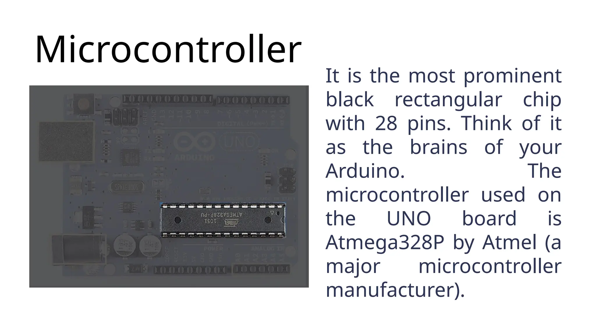
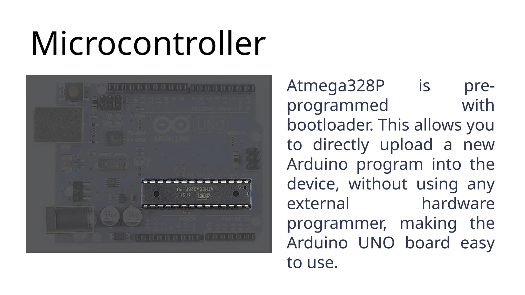
Microcontroller It is themost prominent black rectangular chip with 28 pins. Think of it as the brains of your Arduino. The microcontroller used on the UNO board is Atmega328P by Atmel (a major microcontroller manufacturer).
12.
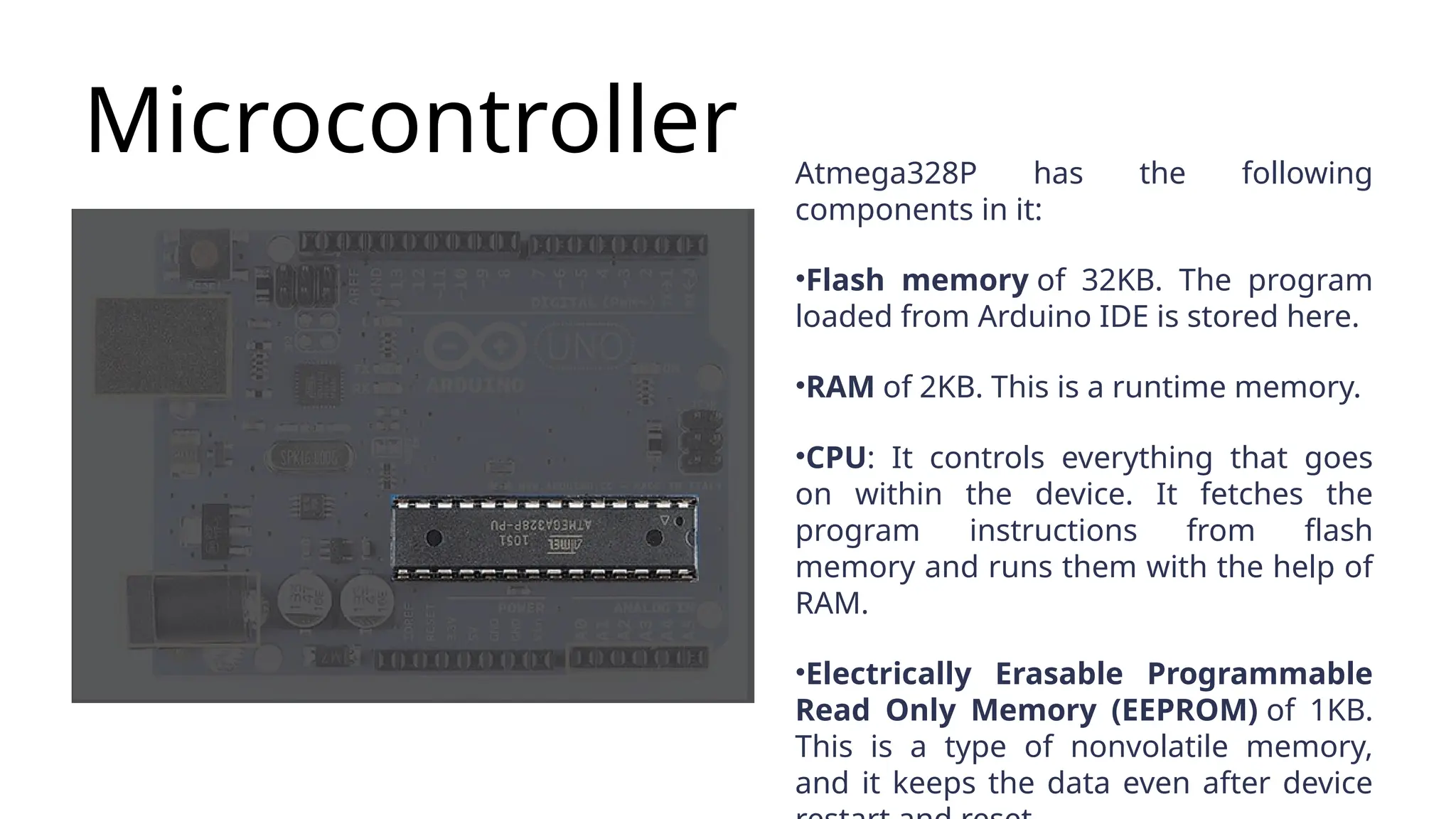
Microcontroller Atmega328P hasthe following components in it: •Flash memory of 32KB. The program loaded from Arduino IDE is stored here. •RAM of 2KB. This is a runtime memory. •CPU: It controls everything that goes on within the device. It fetches the program instructions from flash memory and runs them with the help of RAM. •Electrically Erasable Programmable Read Only Memory (EEPROM) of 1KB. This is a type of nonvolatile memory, and it keeps the data even after device
13.
Microcontroller Atmega328P is pre- programmedwith bootloader. This allows you to directly upload a new Arduino program into the device, without using any external hardware programmer, making the Arduino UNO board easy to use.
14.
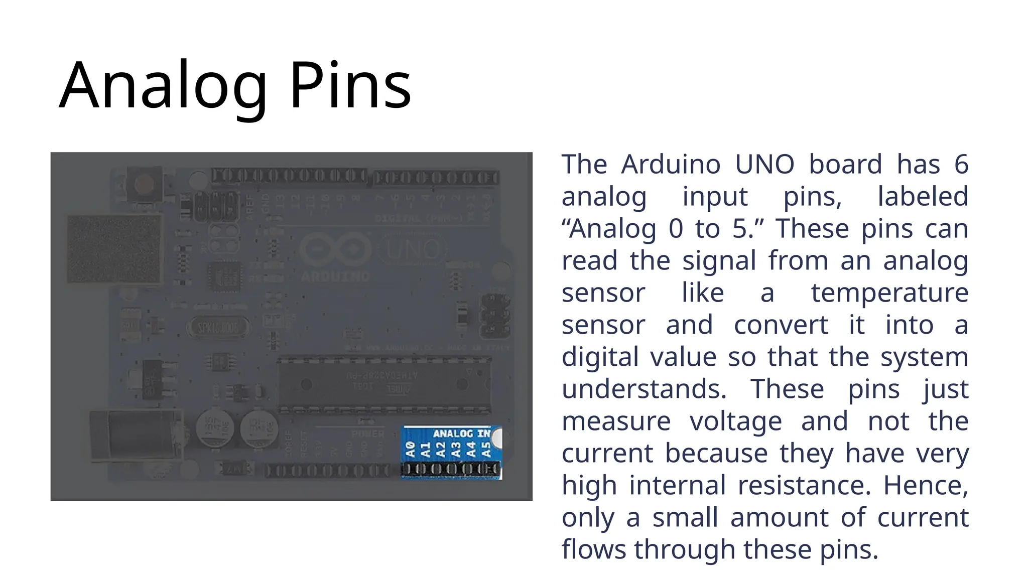
Analog Pins The ArduinoUNO board has 6 analog input pins, labeled “Analog 0 to 5.” These pins can read the signal from an analog sensor like a temperature sensor and convert it into a digital value so that the system understands. These pins just measure voltage and not the current because they have very high internal resistance. Hence, only a small amount of current flows through these pins.
15.
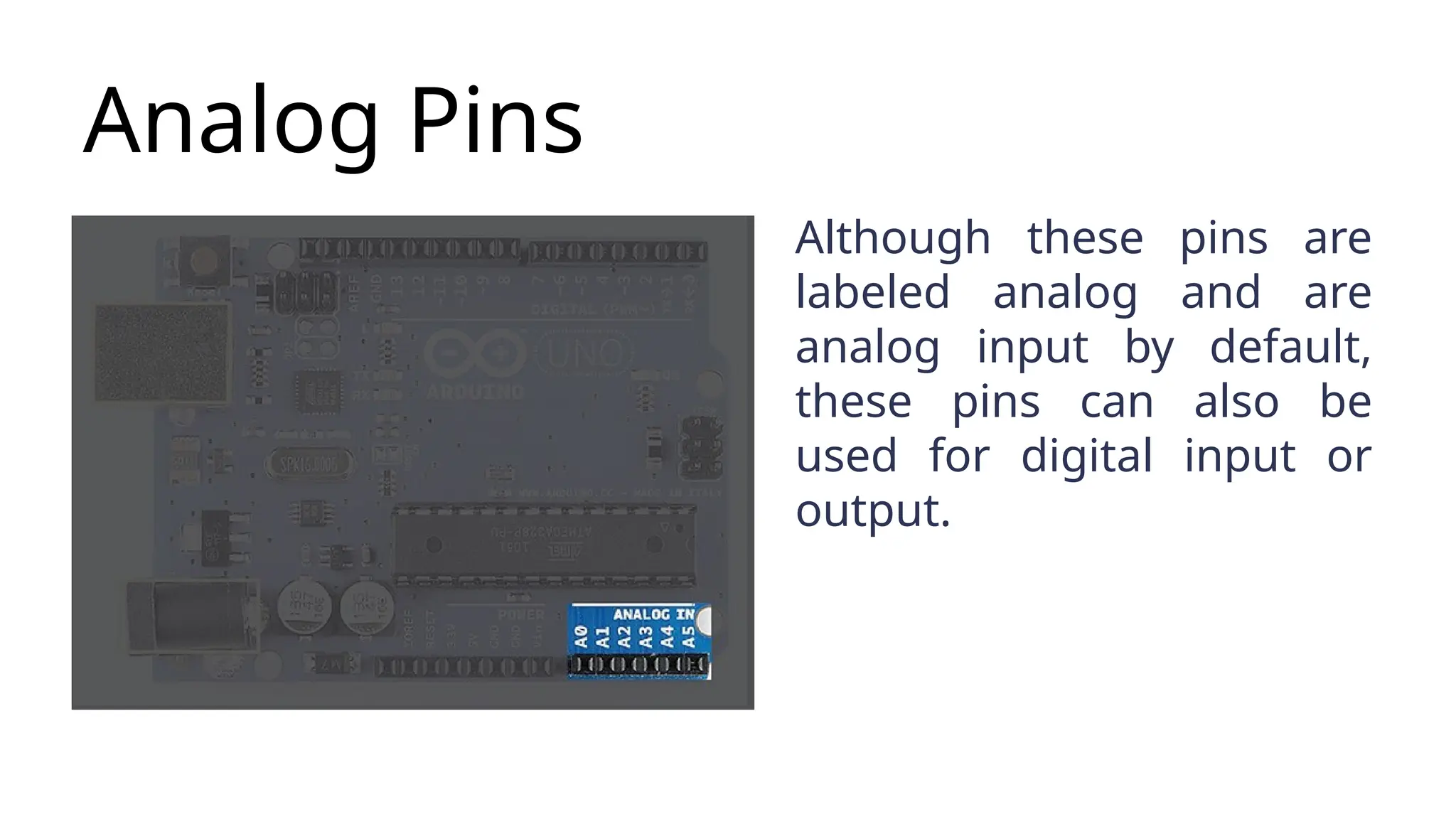
Analog Pins Although thesepins are labeled analog and are analog input by default, these pins can also be used for digital input or output.
16.
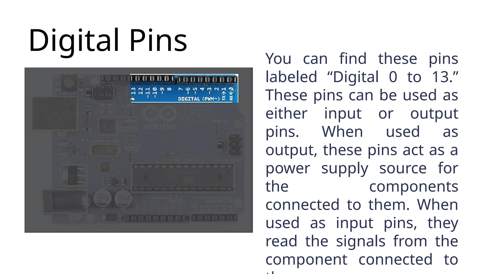
Digital Pins Youcan find these pins labeled “Digital 0 to 13.” These pins can be used as either input or output pins. When used as output, these pins act as a power supply source for the components connected to them. When used as input pins, they read the signals from the component connected to
17.
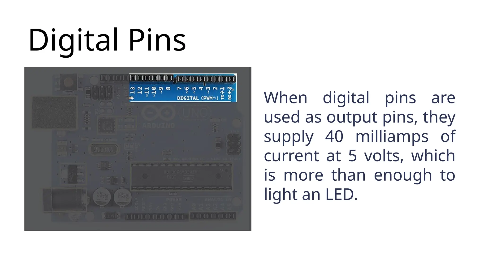
Digital Pins When digitalpins are used as output pins, they supply 40 milliamps of current at 5 volts, which is more than enough to light an LED.
18.
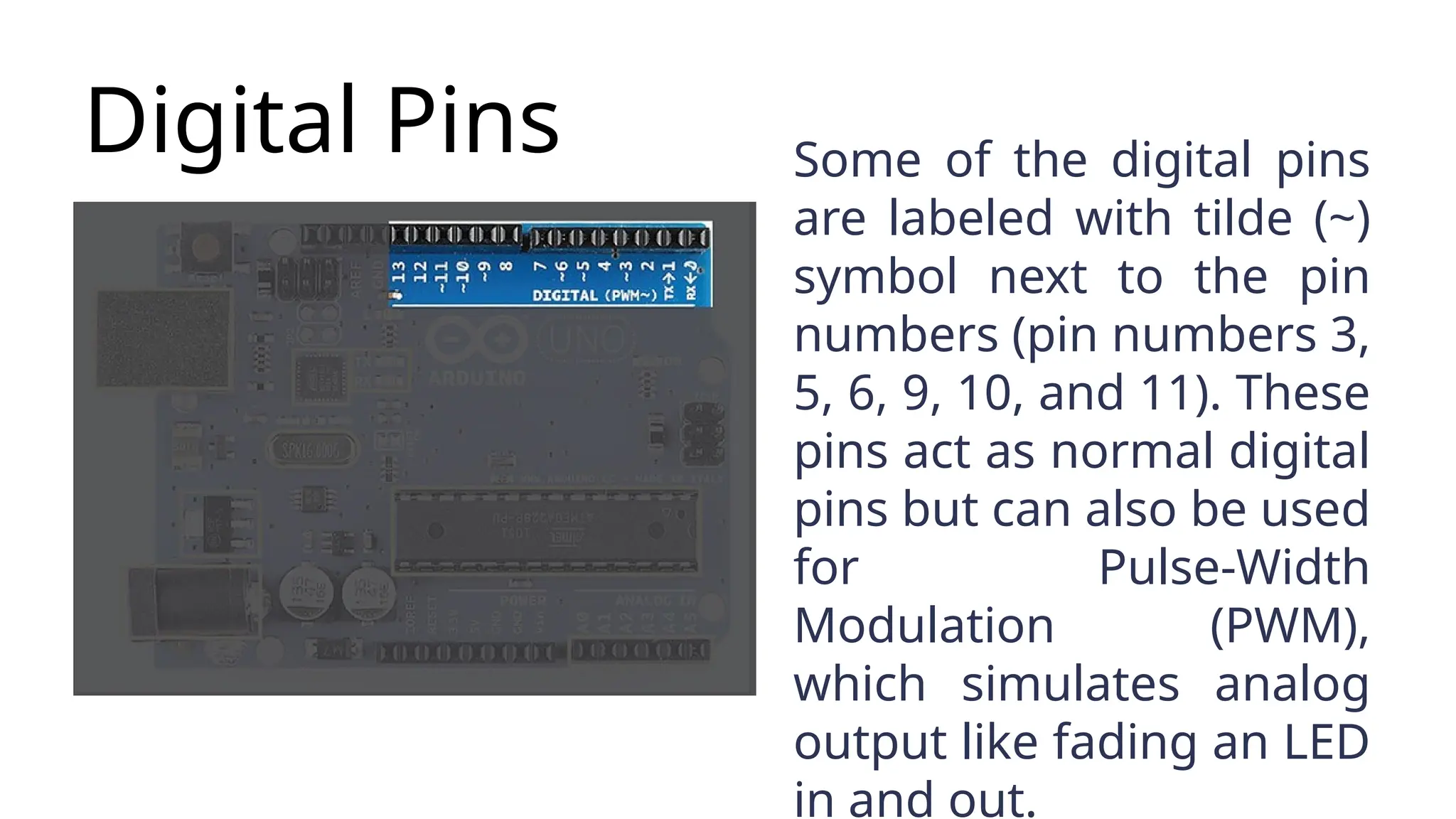
Digital Pins Someof the digital pins are labeled with tilde (~) symbol next to the pin numbers (pin numbers 3, 5, 6, 9, 10, and 11). These pins act as normal digital pins but can also be used for Pulse-Width Modulation (PWM), which simulates analog output like fading an LED in and out.
19.
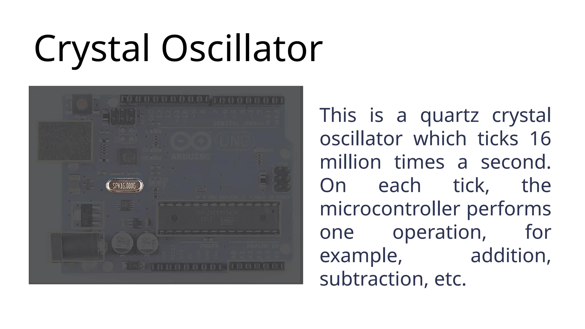
Crystal Oscillator This isa quartz crystal oscillator which ticks 16 million times a second. On each tick, the microcontroller performs one operation, for example, addition, subtraction, etc.
20.
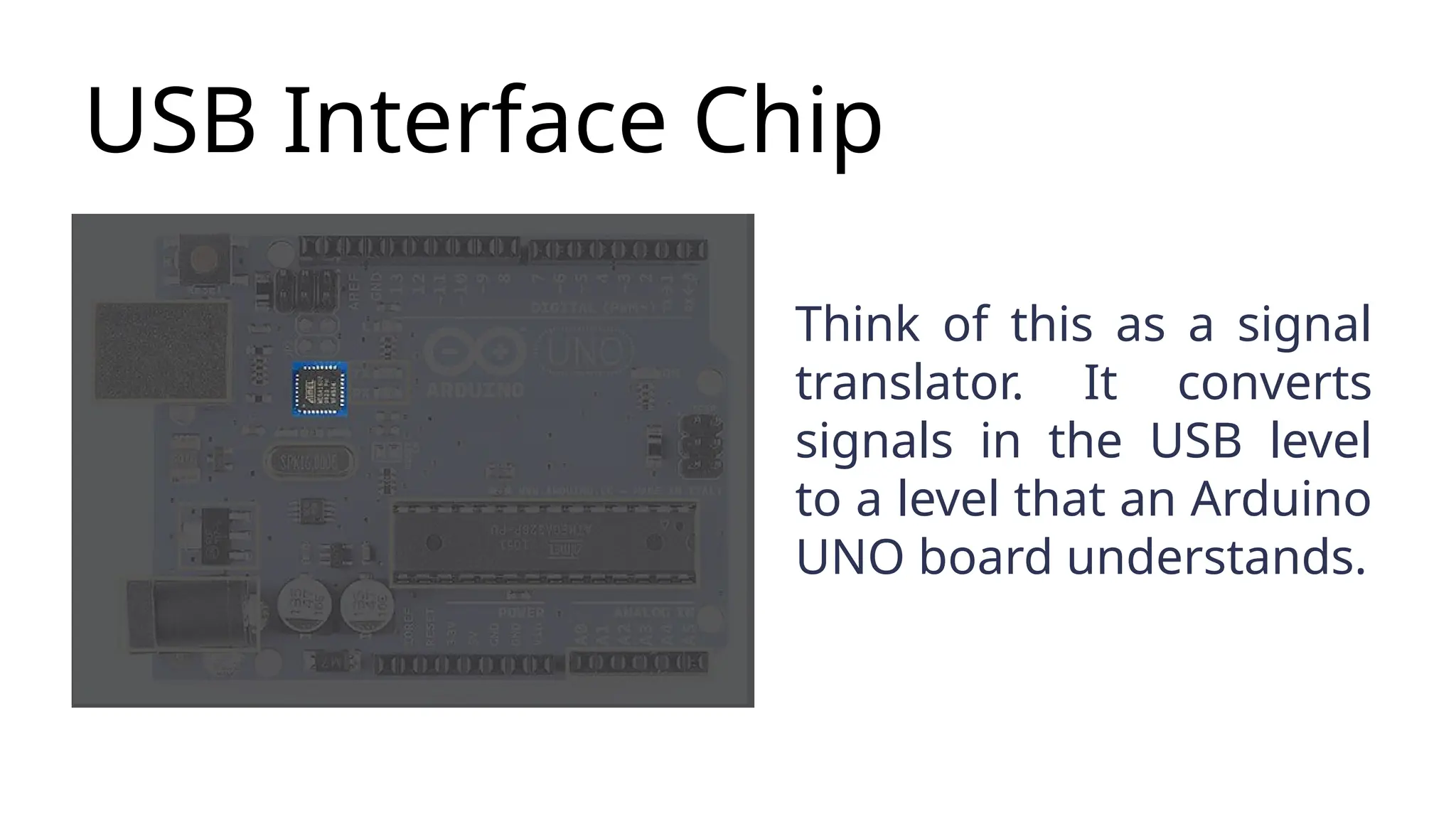
USB Interface Chip Thinkof this as a signal translator. It converts signals in the USB level to a level that an Arduino UNO board understands.
21.
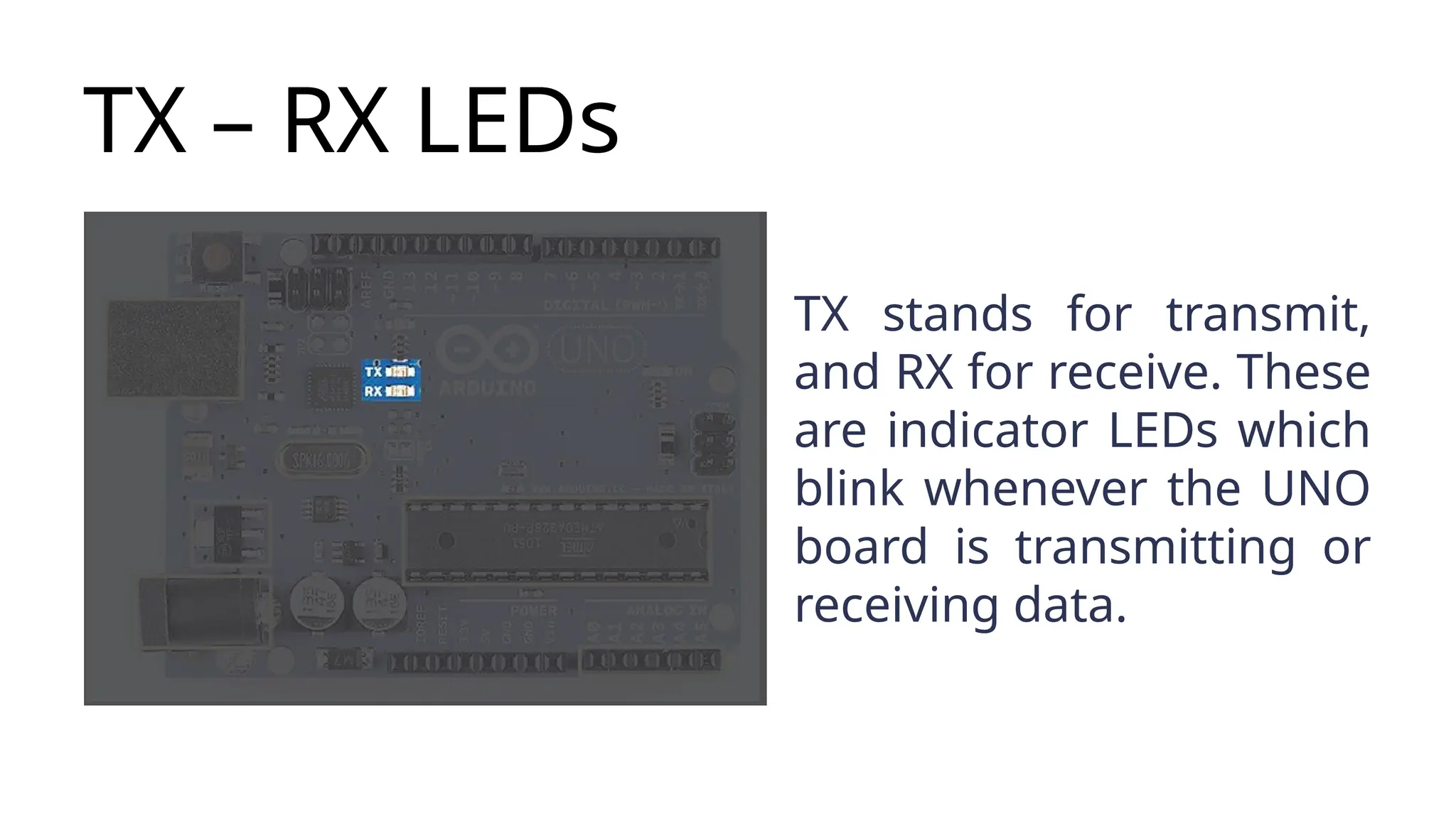
TX – RXLEDs TX stands for transmit, and RX for receive. These are indicator LEDs which blink whenever the UNO board is transmitting or receiving data.