3.1 Timer/Counters SFRs:TMOD,TCON,Timer/Counter- Logic and modes,Simple programs on timer to generate time delay 3.2 Interrupts-SFRs:- IE, IP , Simple programs on interrupts 3.3 Serial communication - SFRs: SCON , SBUF , PCON, Modes of serial communication. Simple programs on serial communication 3.4 I/O port structure and configuration - P0 , P1 , P2 ,P3
The MCS-51 Timers ■The8051 has two registers that can be used either as timers or counters. ■These are referred to as Timer0 and Timer1. ■These timers exist in the SFR area as pairs of 8-bit registers. ■TL0 (8AH) and TH0 (8CH) for Timer0. ■TL1 (8BH) and TH1 (8DH) for Timer1. ■LSB is bit 0 of TLx and MSB is bit 7 of THx.
7.
Usage ■The timers canbe used for: ■Interval timing ■The timer is programmed to overflow at a regular interval and set the timer overflow flag. ▪ Overflow means reaching maximum count of FFFFH. ■Event counting ■Determine the number of occurrences of an event. An event is any external stimulus that provides a 1- to-0 transition on a pin of the 8051. ■Baud rate generation for the built-in serial port.
8.
Incrementing ■ When usedas timers, the registers are incremented once per machine cycle. ■Each machine cycle is 12 clock cycles. ■The count frequency = (system clock frequency) / 12 ■ When used as counters, the registers will be incremented once on every 1-0 (negative edge) on the appropriate input pin. ■T0 – P3.4 ■T1 – P3.5 ■The pins must be held high for one complete machine cycle and then low for one complete machine cycle.
9.
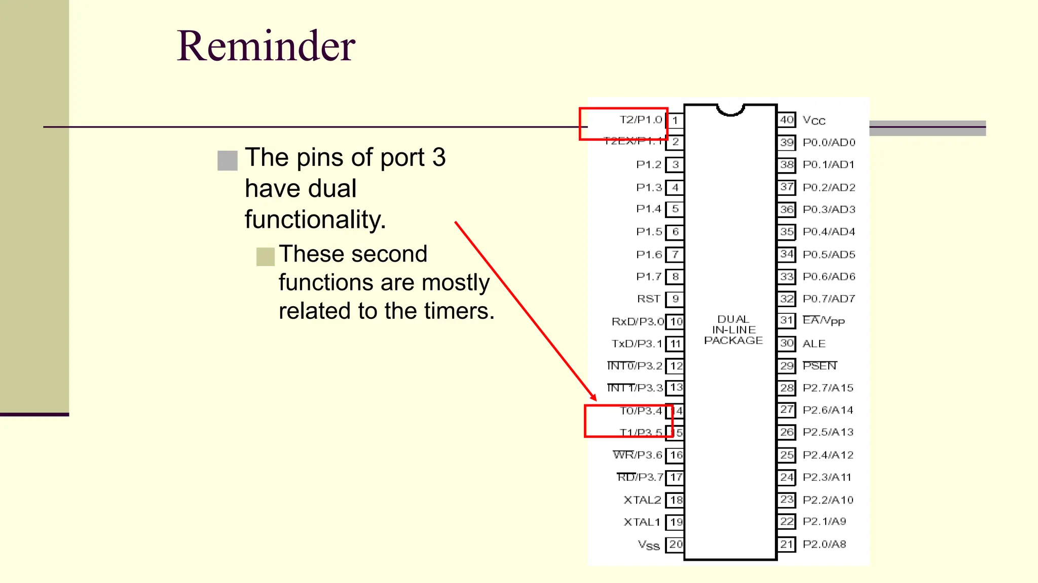
Reminder ■ The pinsof port 3 have dual functionality. ■These second functions are mostly related to the timers.
10.
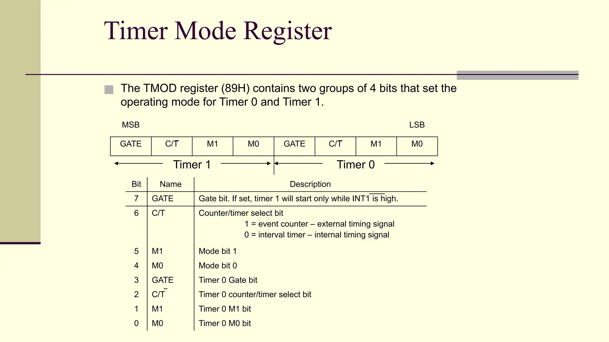
Timer Mode Register ■The TMOD register (89H) contains two groups of 4 bits that set the operating mode for Timer 0 and Timer 1. MSB LSB GATE C/T M1 M0 GATE C/T M1 M0 Timer 1 Timer 0 Bit Name Description 7 GATE Gate bit. If set, timer 1 will start only while INT1 is high. 6 C/T Counter/timer select bit 1 = event counter – external timing signal 0 = interval timer – internal timing signal 5 M1 Mode bit 1 4 M0 Mode bit 0 3 GATE Timer 0 Gate bit 2 C/T Timer 0 counter/timer select bit 1 M1 Timer 0 M1 bit 0 M0 Timer 0 M0 bit
11.
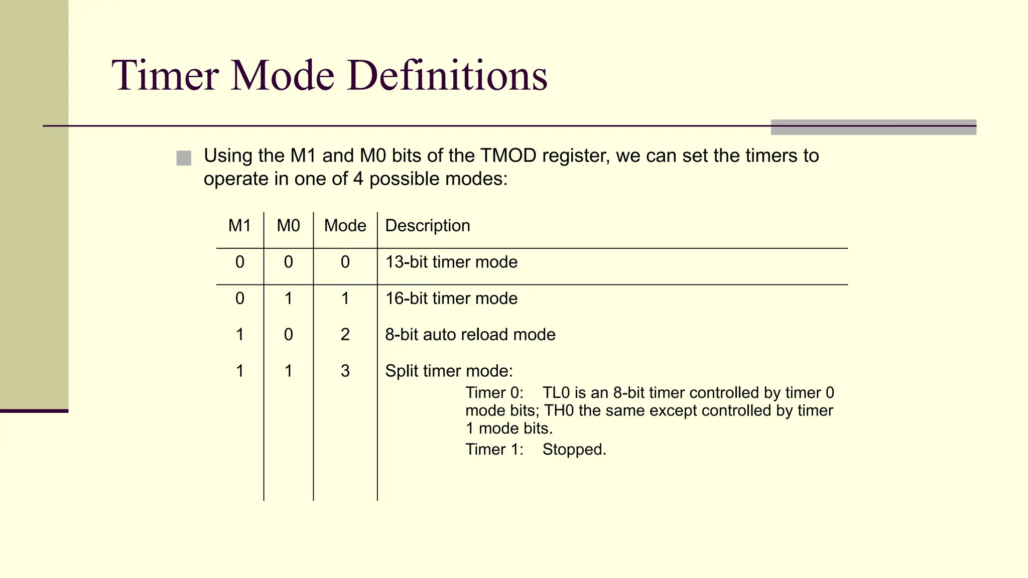
Timer Mode Definitions ■Using the M1 and M0 bits of the TMOD register, we can set the timers to operate in one of 4 possible modes: M1 M0 Mode Description 0 0 0 13-bit timer mode 0 1 1 16-bit timer mode 1 0 2 8-bit auto reload mode 1 1 3 Split timer mode: Timer 0: TL0 is an 8-bit timer controlled by timer 0 mode bits; TH0 the same except controlled by timer 1 mode bits. Timer 1: Stopped.
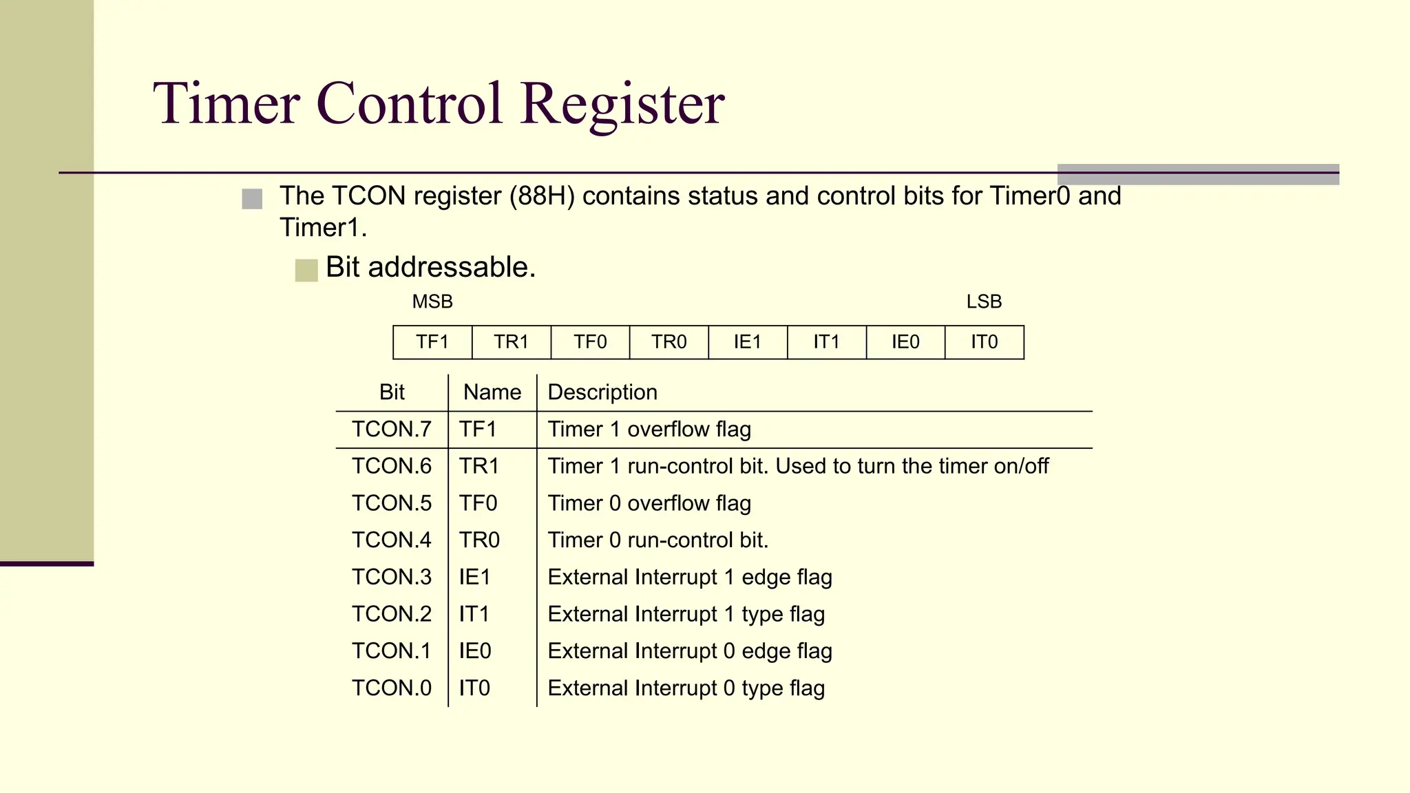
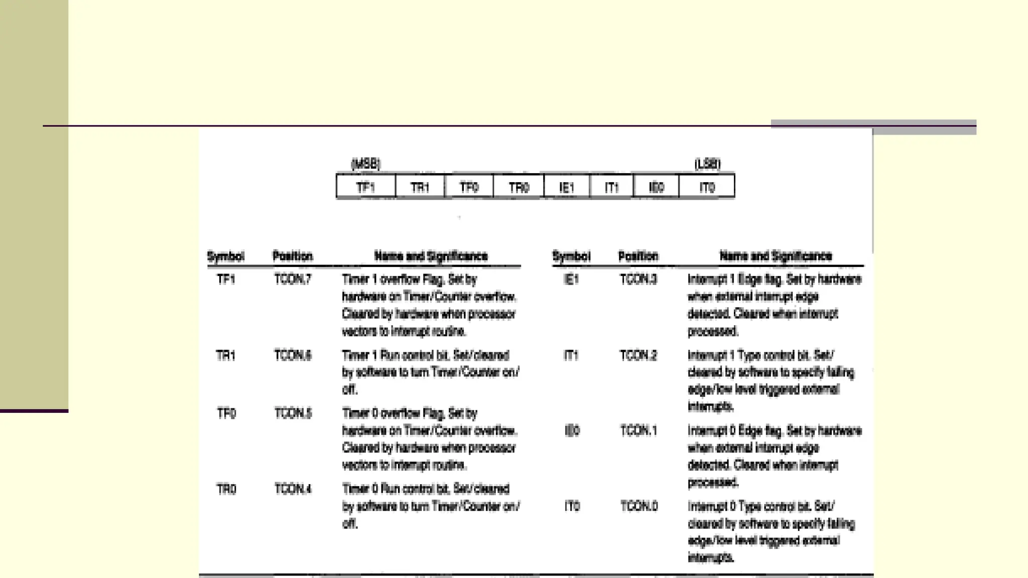
Timer Control Register ■The TCON register (88H) contains status and control bits for Timer0 and Timer1. ■ Bit addressable. MSB LSB TF1 TR1 TF0 TR0 IE1 IT1 IE0 IT0 Bit Name Description TCON.7 TF1 Timer 1 overflow flag TCON.6 TR1 Timer 1 run-control bit. Used to turn the timer on/off TCON.5 TF0 Timer 0 overflow flag TCON.4 TR0 Timer 0 run-control bit. TCON.3 IE1 External Interrupt 1 edge flag TCON.2 IT1 External Interrupt 1 type flag TCON.1 IE0 External Interrupt 0 edge flag TCON.0 IT0 External Interrupt 0 type flag
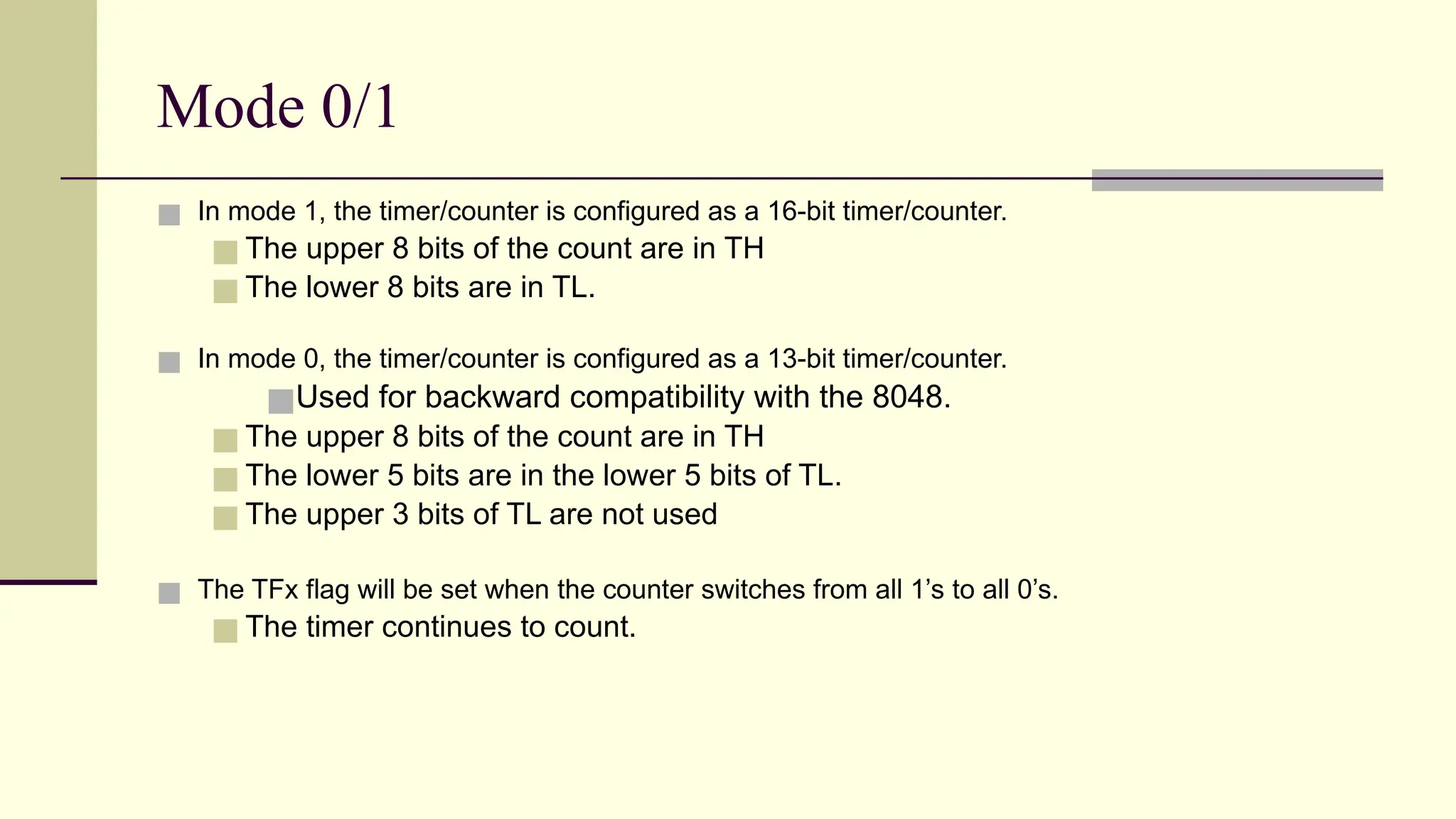
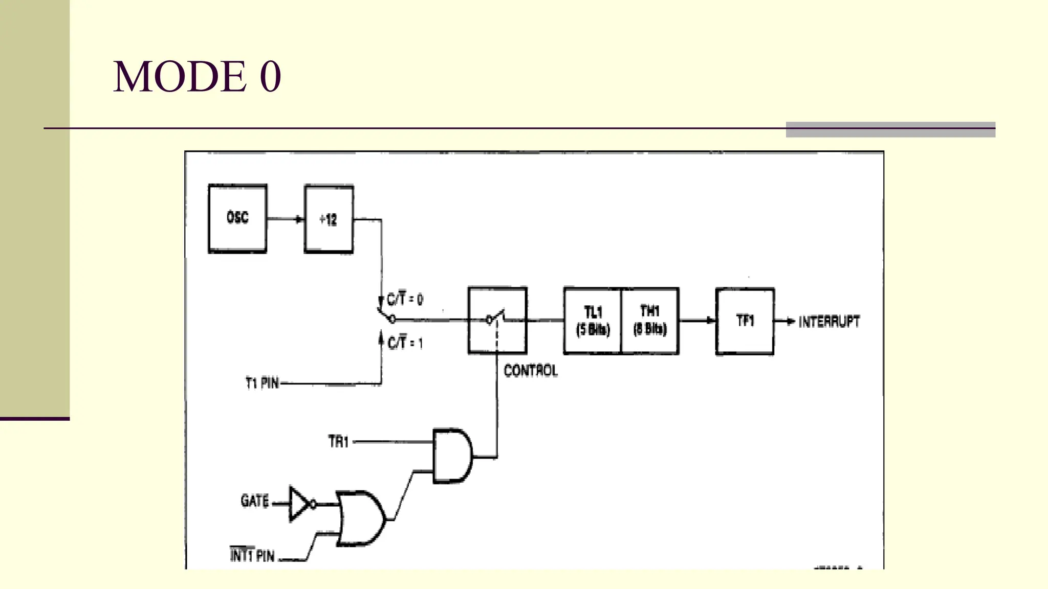
Mode 0/1 ■ Inmode 1, the timer/counter is configured as a 16-bit timer/counter. ■ The upper 8 bits of the count are in TH ■ The lower 8 bits are in TL. ■ In mode 0, the timer/counter is configured as a 13-bit timer/counter. ■Used for backward compatibility with the 8048. ■ The upper 8 bits of the count are in TH ■ The lower 5 bits are in the lower 5 bits of TL. ■ The upper 3 bits of TL are not used ■ The TFx flag will be set when the counter switches from all 1’s to all 0’s. ■ The timer continues to count.
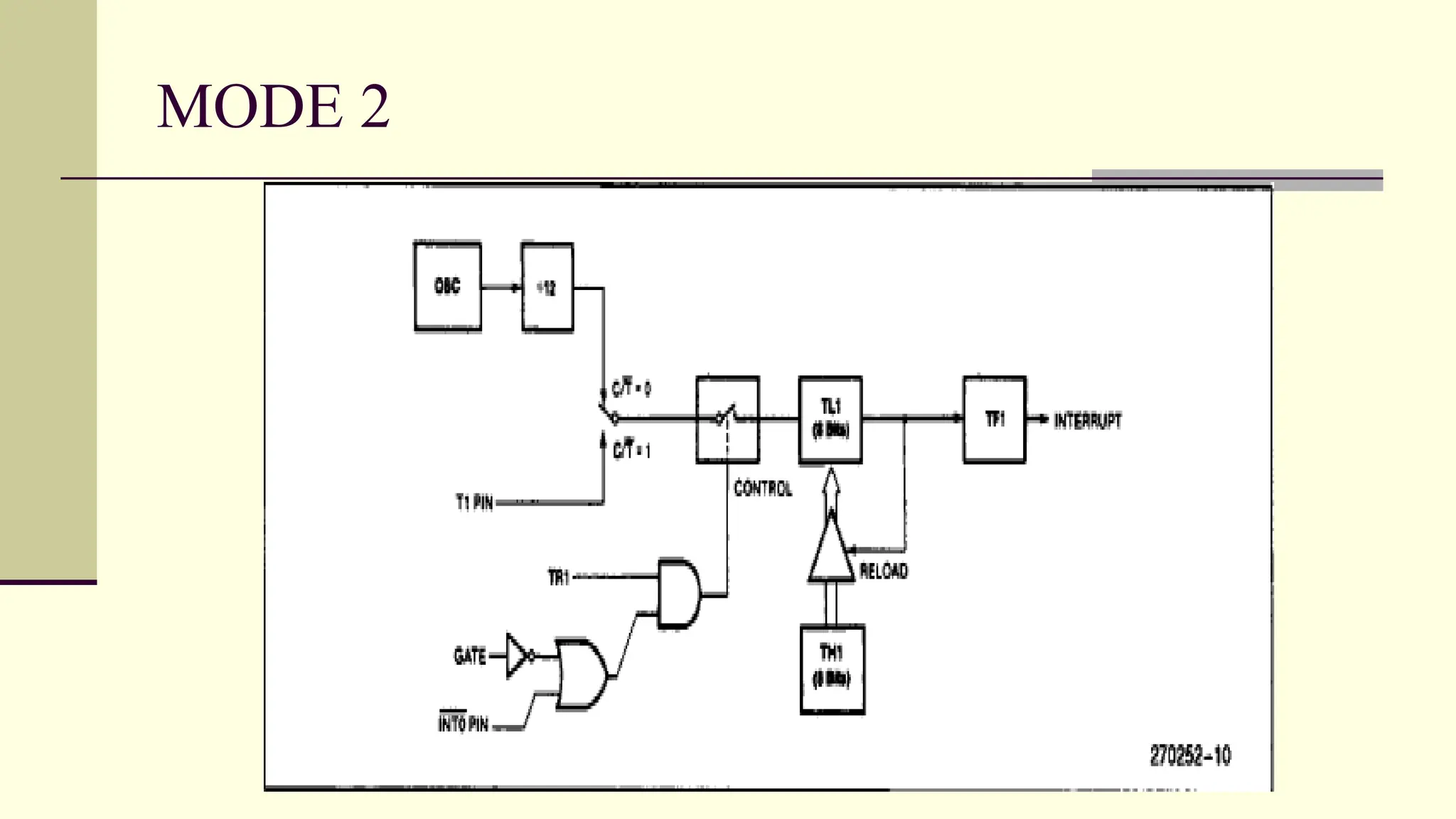
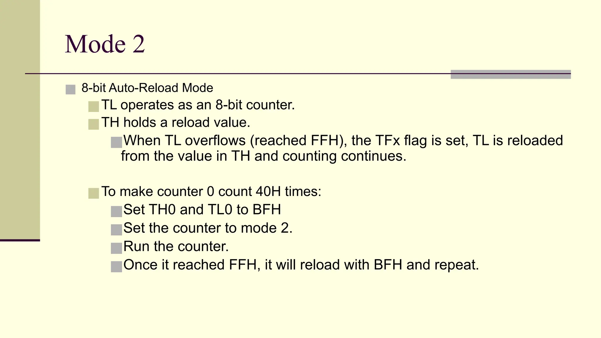
Mode 2 ■ 8-bitAuto-Reload Mode ■TL operates as an 8-bit counter. ■TH holds a reload value. ■When TL overflows (reached FFH), the TFx flag is set, TL is reloaded from the value in TH and counting continues. ■To make counter 0 count 40H times: ■Set TH0 and TL0 to BFH ■Set the counter to mode 2. ■Run the counter. ■Once it reached FFH, it will reload with BFH and repeat.
25.
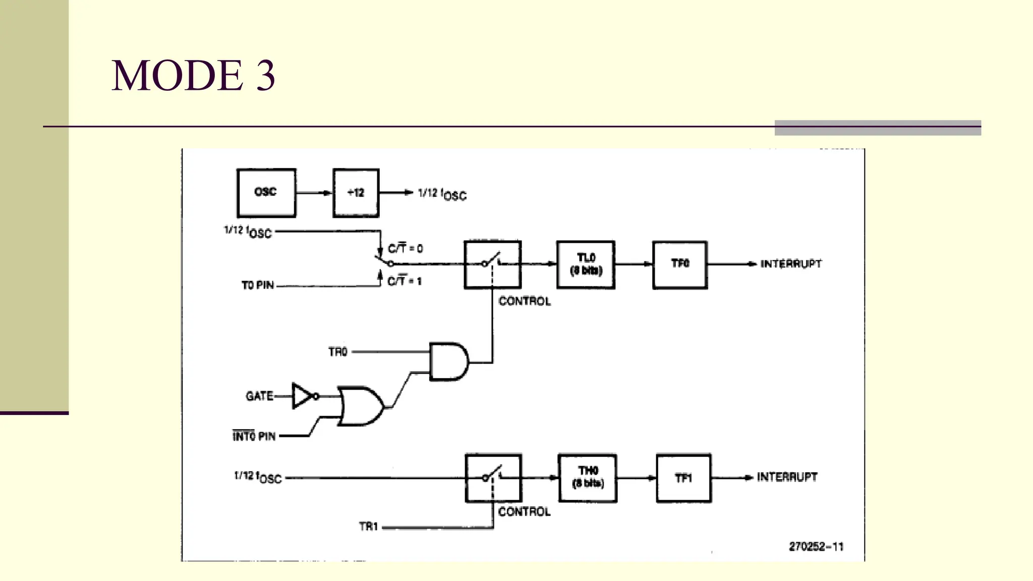
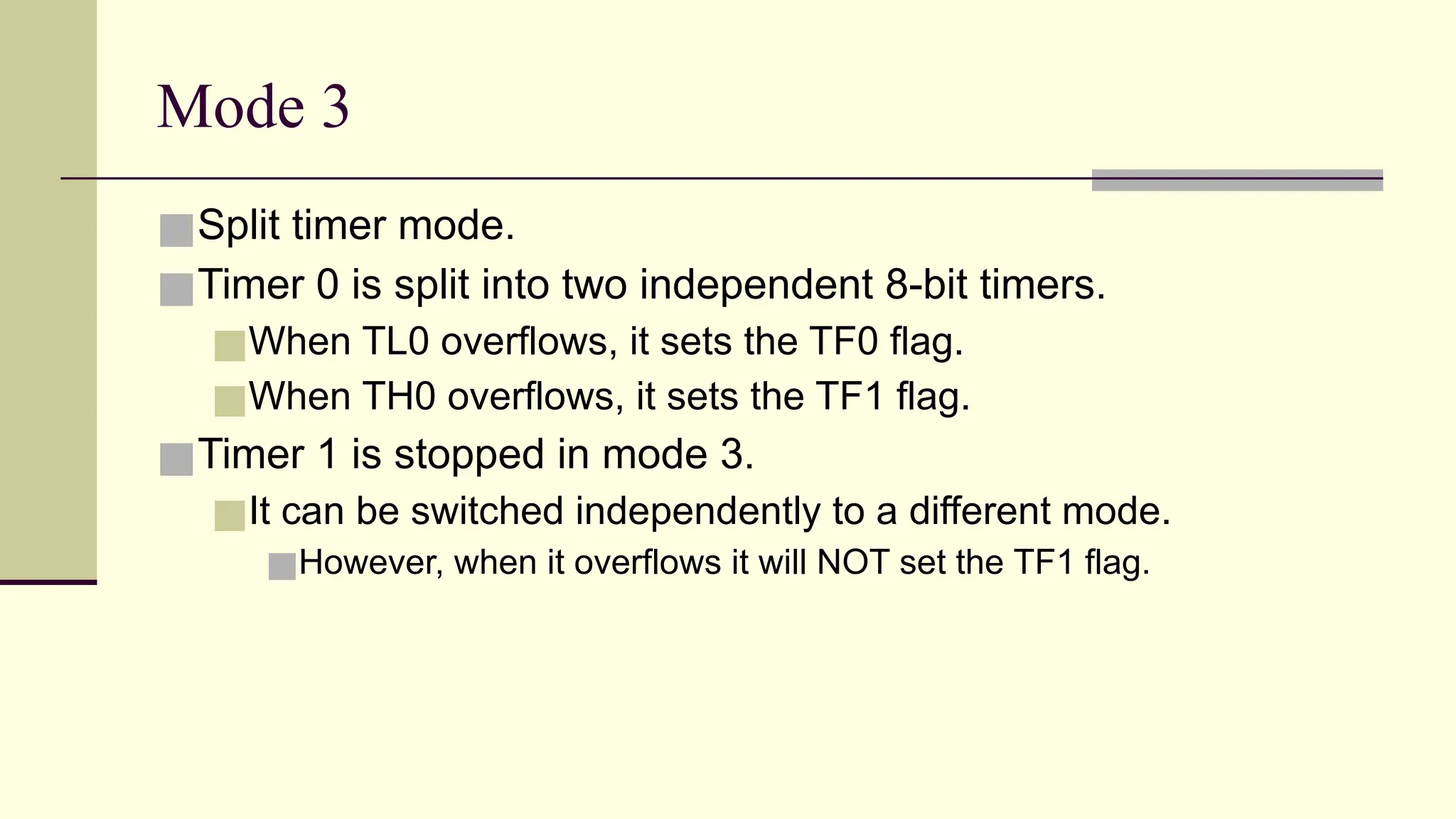
Mode 3 ■Split timermode. ■Timer 0 is split into two independent 8-bit timers. ■When TL0 overflows, it sets the TF0 flag. ■When TH0 overflows, it sets the TF1 flag. ■Timer 1 is stopped in mode 3. ■It can be switched independently to a different mode. ■However, when it overflows it will NOT set the TF1 flag.
26.
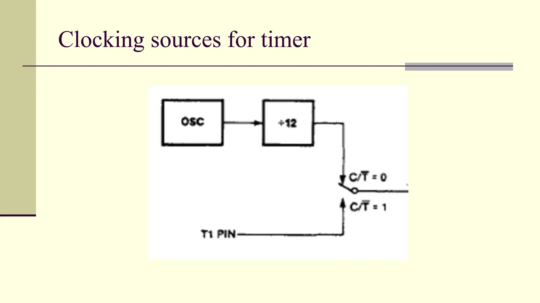
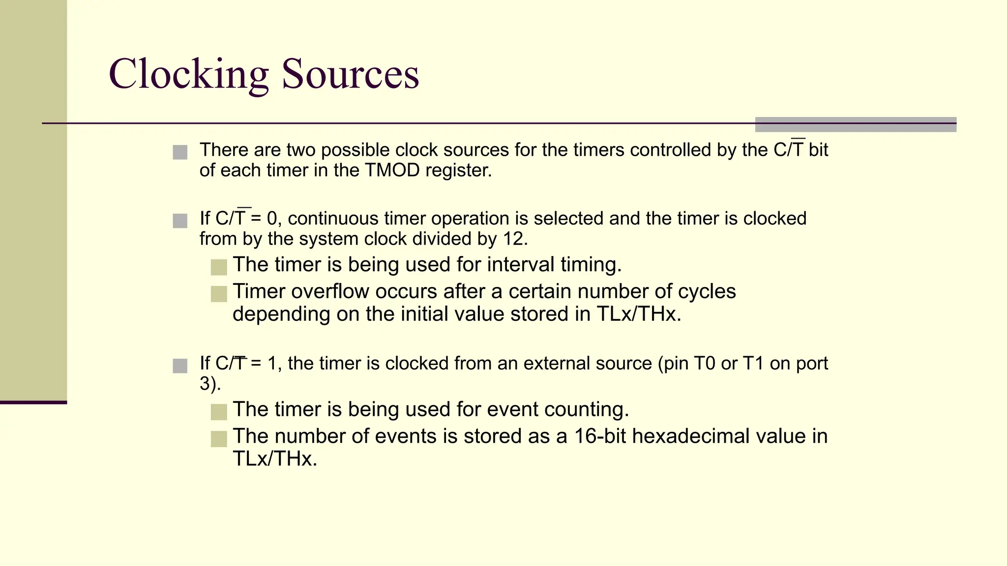
Clocking Sources ■ Thereare two possible clock sources for the timers controlled by the C/T bit of each timer in the TMOD register. ■ If C/T = 0, continuous timer operation is selected and the timer is clocked from by the system clock divided by 12. ■ The timer is being used for interval timing. ■ Timer overflow occurs after a certain number of cycles depending on the initial value stored in TLx/THx. ■ If C/T = 1, the timer is clocked from an external source (pin T0 or T1 on port 3). ■ The timer is being used for event counting. ■ The number of events is stored as a 16-bit hexadecimal value in TLx/THx.
27.
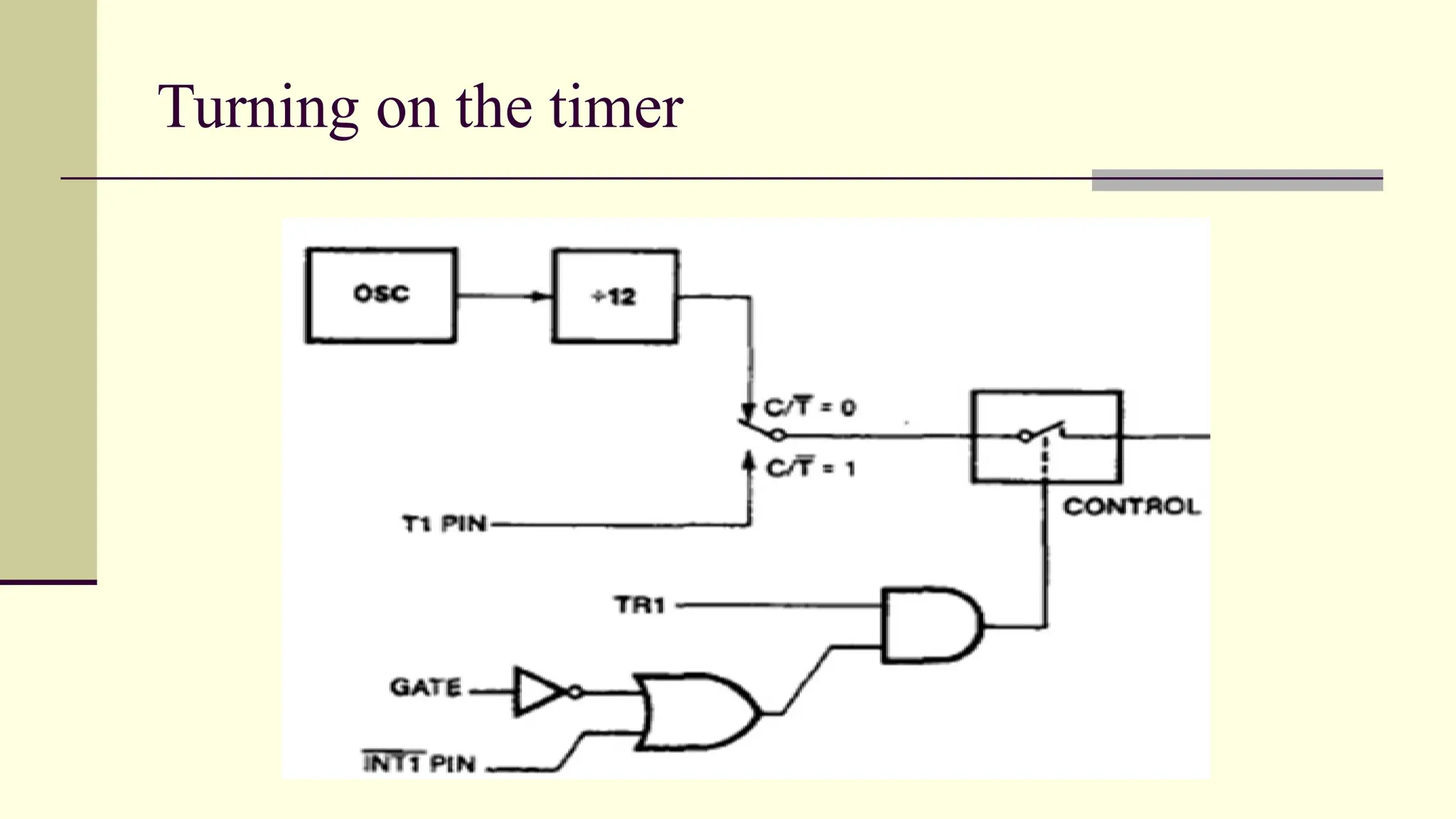
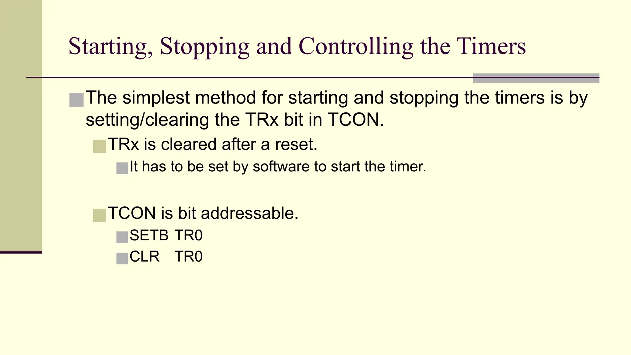
Starting, Stopping andControlling the Timers ■The simplest method for starting and stopping the timers is by setting/clearing the TRx bit in TCON. ■TRx is cleared after a reset. ■It has to be set by software to start the timer. ■TCON is bit addressable. ■SETB TR0 ■CLR TR0
28.
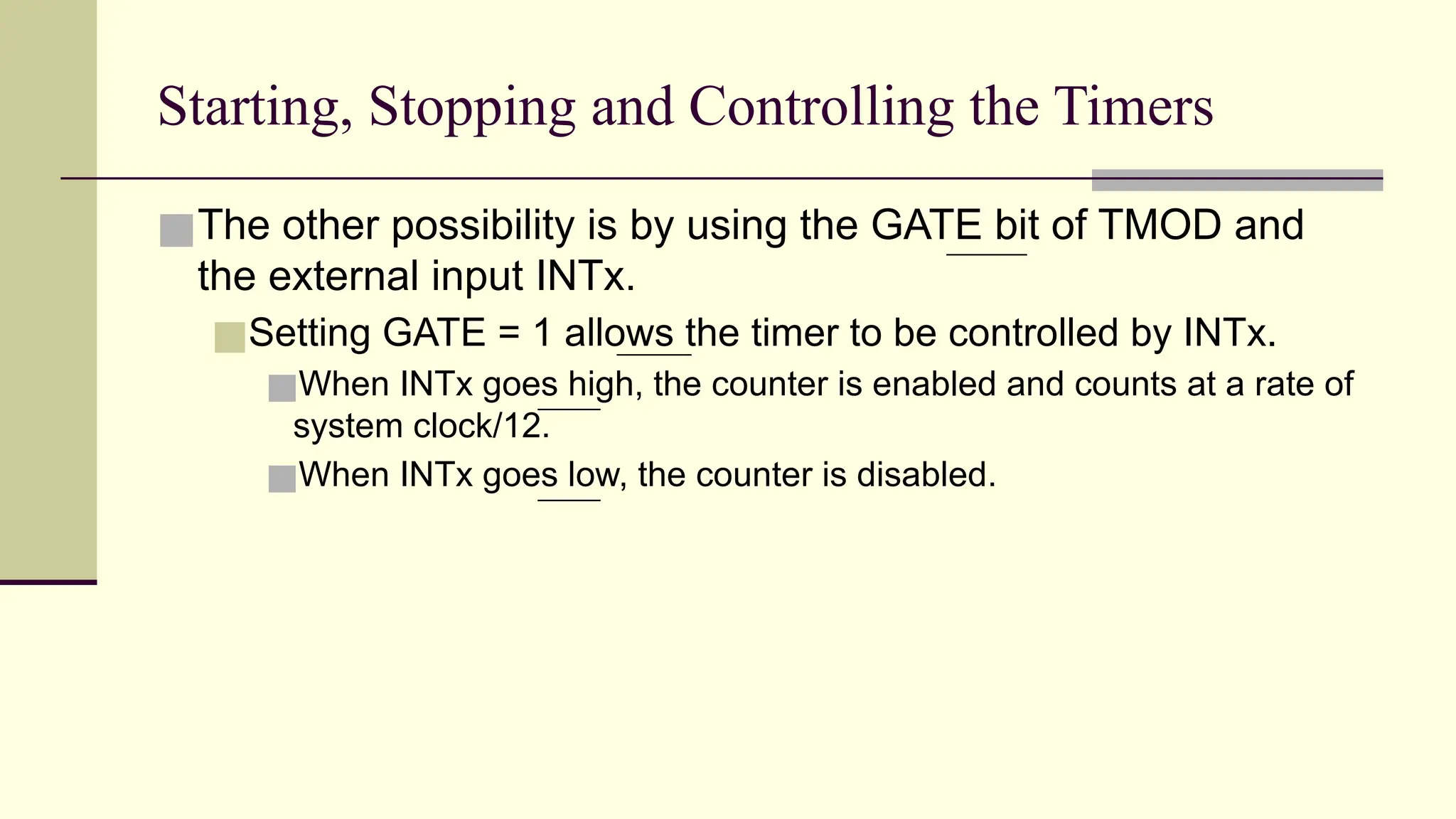
Starting, Stopping andControlling the Timers ■The other possibility is by using the GATE bit of TMOD and the external input INTx. ■Setting GATE = 1 allows the timer to be controlled by INTx. ■When INTx goes high, the counter is enabled and counts at a rate of system clock/12. ■When INTx goes low, the counter is disabled.
29.
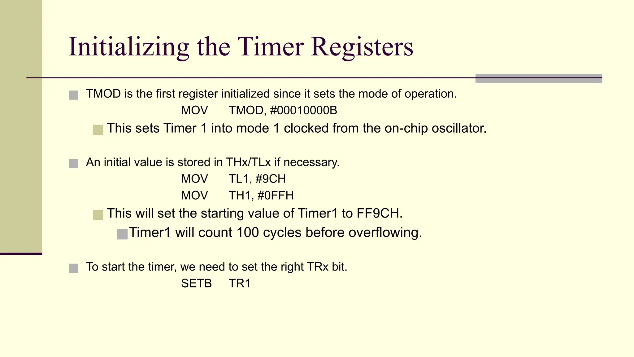
Initializing the TimerRegisters ■ TMOD is the first register initialized since it sets the mode of operation. MOV TMOD, #00010000B ■ This sets Timer 1 into mode 1 clocked from the on-chip oscillator. ■ An initial value is stored in THx/TLx if necessary. MOV TL1, #9CH MOV TH1, #0FFH ■ This will set the starting value of Timer1 to FF9CH. ■Timer1 will count 100 cycles before overflowing. ■ To start the timer, we need to set the right TRx bit. SETB TR1
30.
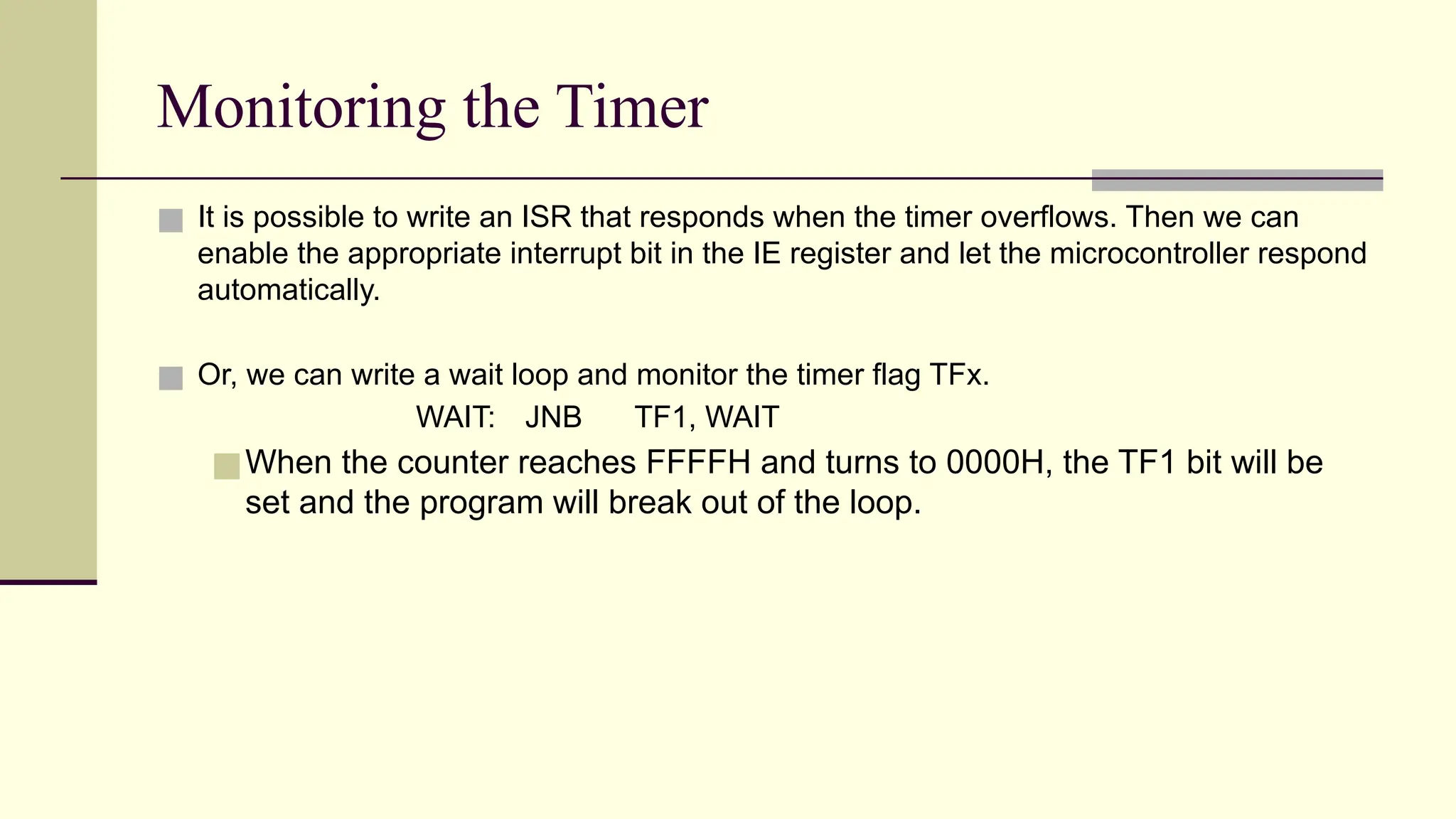
Monitoring the Timer ■It is possible to write an ISR that responds when the timer overflows. Then we can enable the appropriate interrupt bit in the IE register and let the microcontroller respond automatically. ■ Or, we can write a wait loop and monitor the timer flag TFx. WAIT: JNB TF1, WAIT ■When the counter reaches FFFFH and turns to 0000H, the TF1 bit will be set and the program will break out of the loop.
31.
Responding to aTimer Overflow ■When the timer overflows, we need to stop it and then reset the TFx bit so that we don’t generate false overflows. CLR TR1 CLR TF1
32.
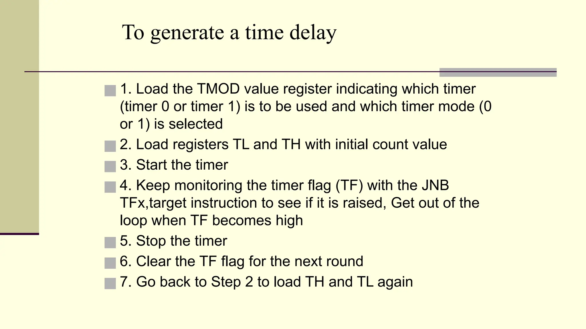
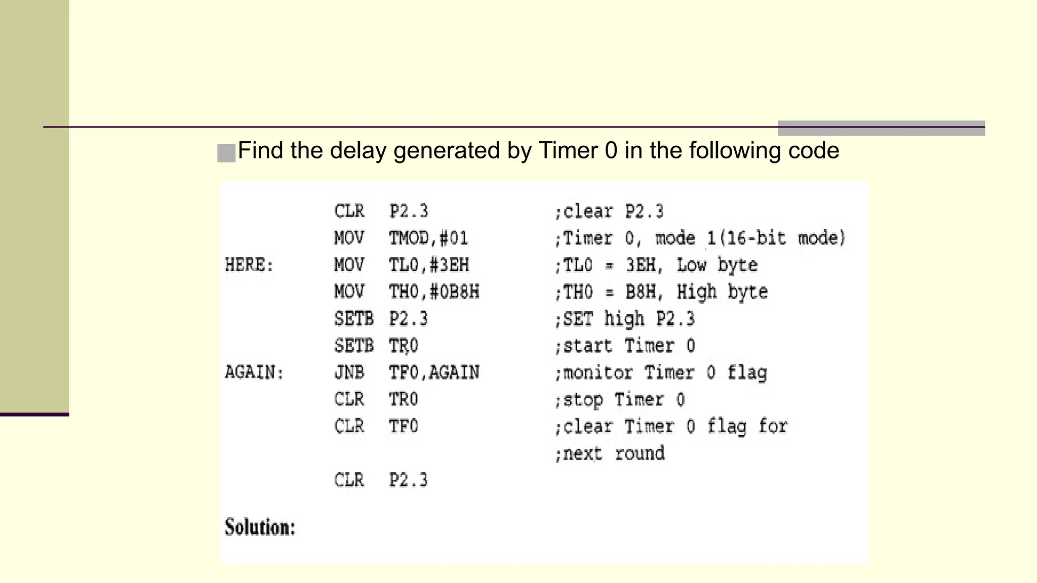
To generate atime delay ■ 1. Load the TMOD value register indicating which timer (timer 0 or timer 1) is to be used and which timer mode (0 or 1) is selected ■ 2. Load registers TL and TH with initial count value ■ 3. Start the timer ■ 4. Keep monitoring the timer flag (TF) with the JNB TFx,target instruction to see if it is raised, Get out of the loop when TF becomes high ■ 5. Stop the timer ■ 6. Clear the TF flag for the next round ■ 7. Go back to Step 2 to load TH and TL again
33.
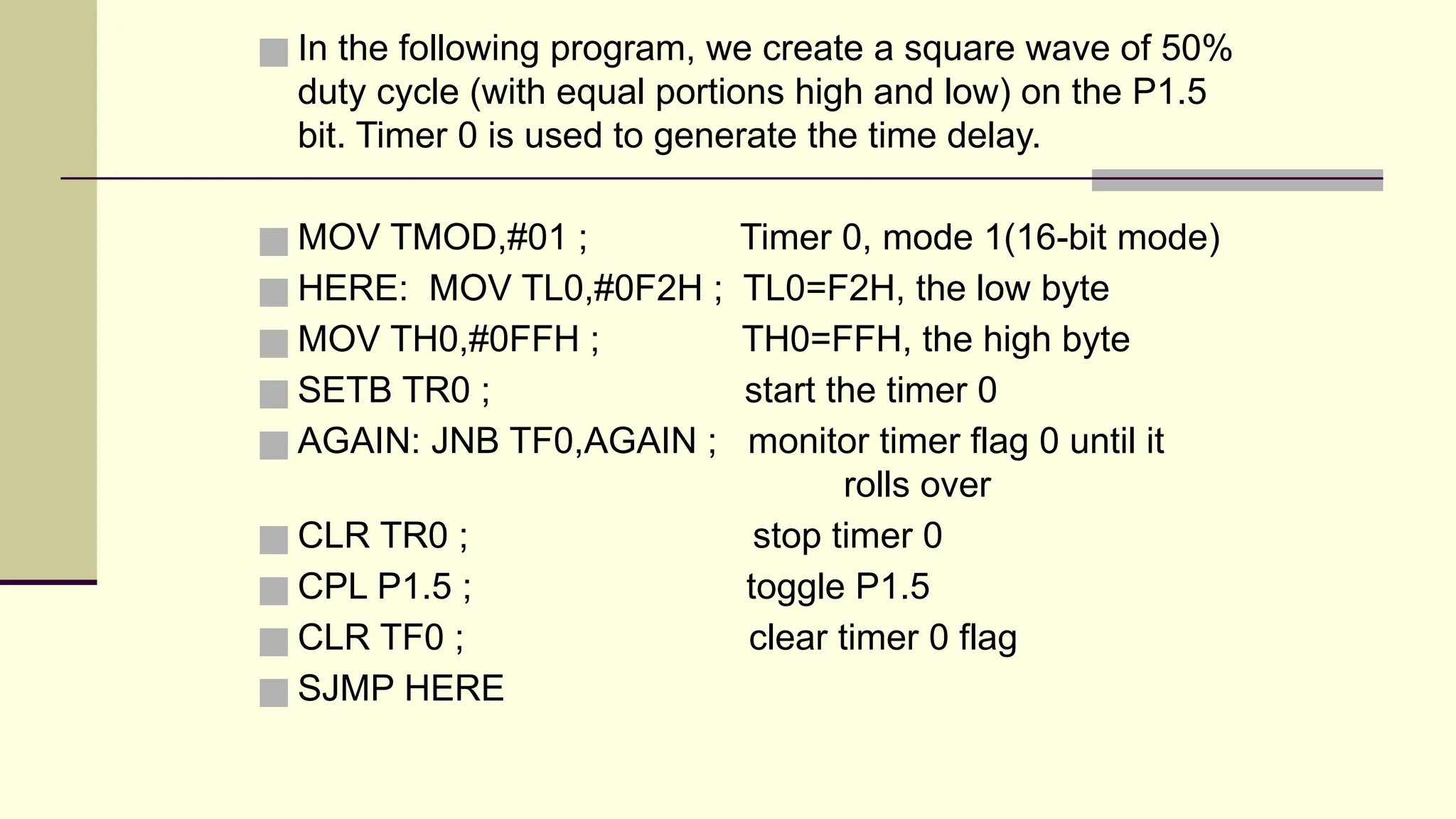
■ In thefollowing program, we create a square wave of 50% duty cycle (with equal portions high and low) on the P1.5 bit. Timer 0 is used to generate the time delay. ■ MOV TMOD,#01 ; Timer 0, mode 1(16-bit mode) ■ HERE: MOV TL0,#0F2H ; TL0=F2H, the low byte ■ MOV TH0,#0FFH ; TH0=FFH, the high byte ■ SETB TR0 ; start the timer 0 ■ AGAIN: JNB TF0,AGAIN ; monitor timer flag 0 until it rolls over ■ CLR TR0 ; stop timer 0 ■ CPL P1.5 ; toggle P1.5 ■ CLR TF0 ; clear timer 0 flag ■ SJMP HERE
34.
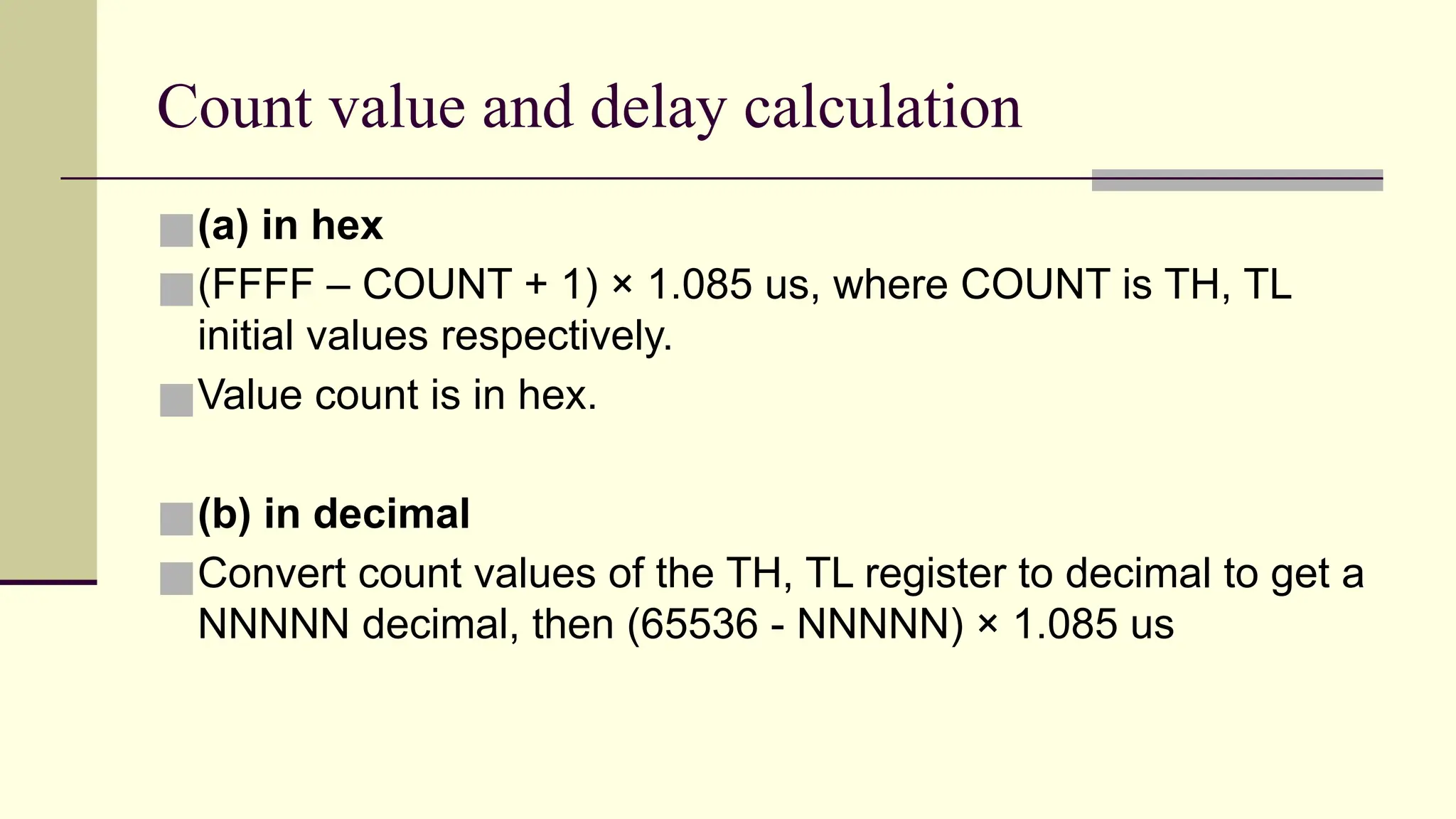
Count value anddelay calculation ■(a) in hex ■(FFFF – COUNT + 1) × 1.085 us, where COUNT is TH, TL initial values respectively. ■Value count is in hex. ■(b) in decimal ■Convert count values of the TH, TL register to decimal to get a NNNNN decimal, then (65536 - NNNNN) × 1.085 us
35.
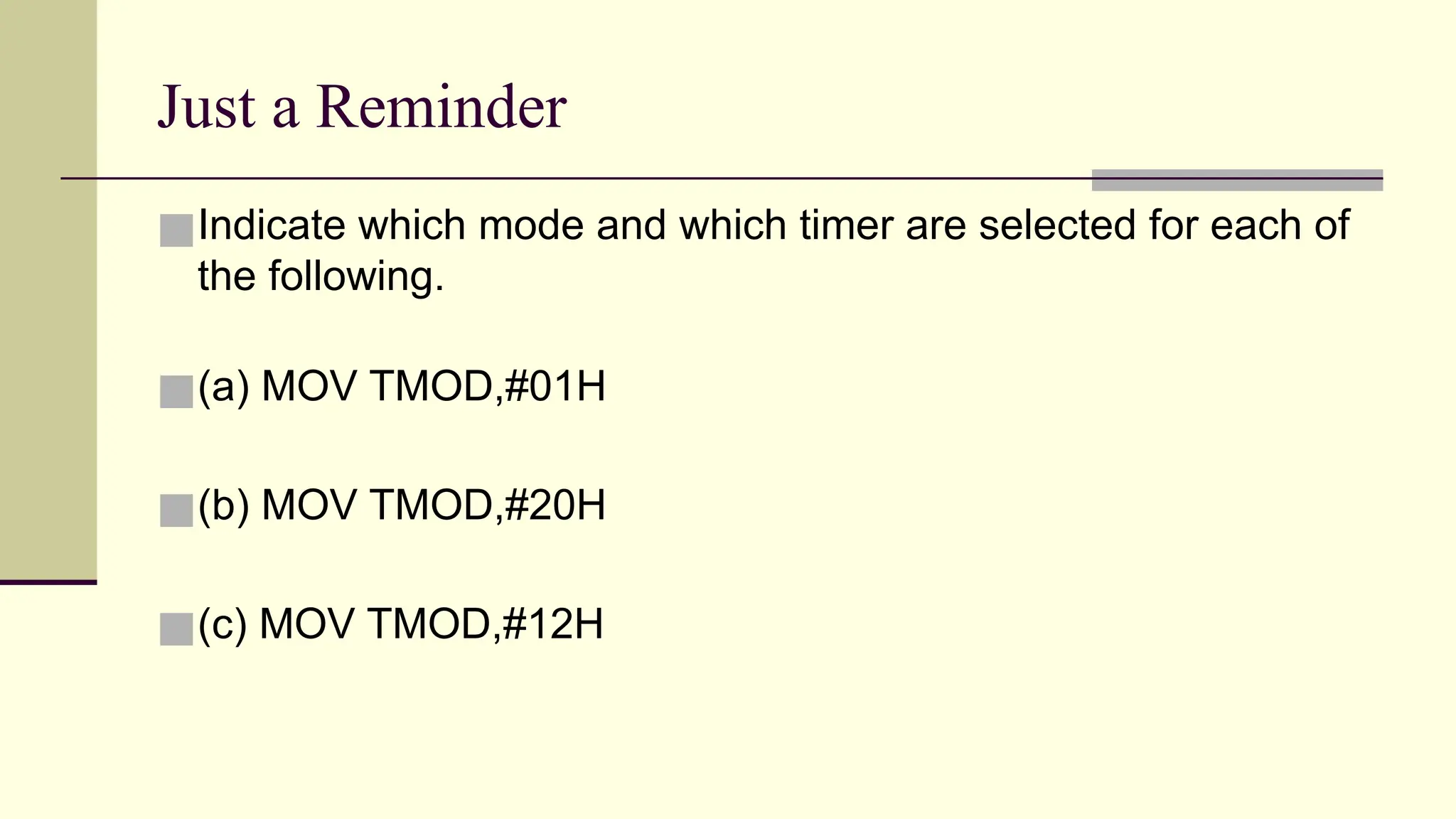
Just a Reminder ■Indicatewhich mode and which timer are selected for each of the following. ■(a) MOV TMOD,#01H ■(b) MOV TMOD,#20H ■(c) MOV TMOD,#12H
36.
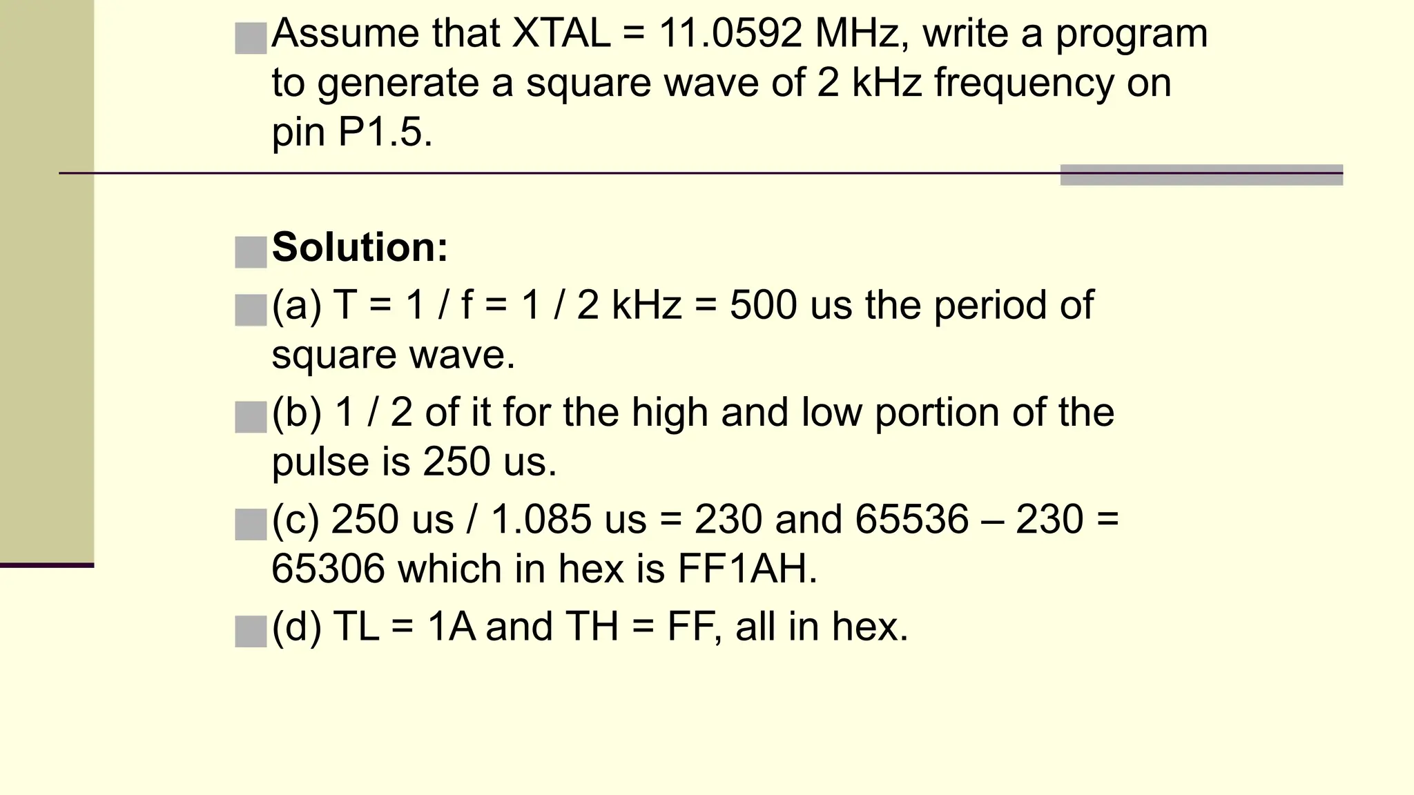
■Assume that XTAL= 11.0592 MHz, write a program to generate a square wave of 2 kHz frequency on pin P1.5. ■Solution: ■(a) T = 1 / f = 1 / 2 kHz = 500 us the period of square wave. ■(b) 1 / 2 of it for the high and low portion of the pulse is 250 us. ■(c) 250 us / 1.085 us = 230 and 65536 – 230 = 65306 which in hex is FF1AH. ■(d) TL = 1A and TH = FF, all in hex.
37.
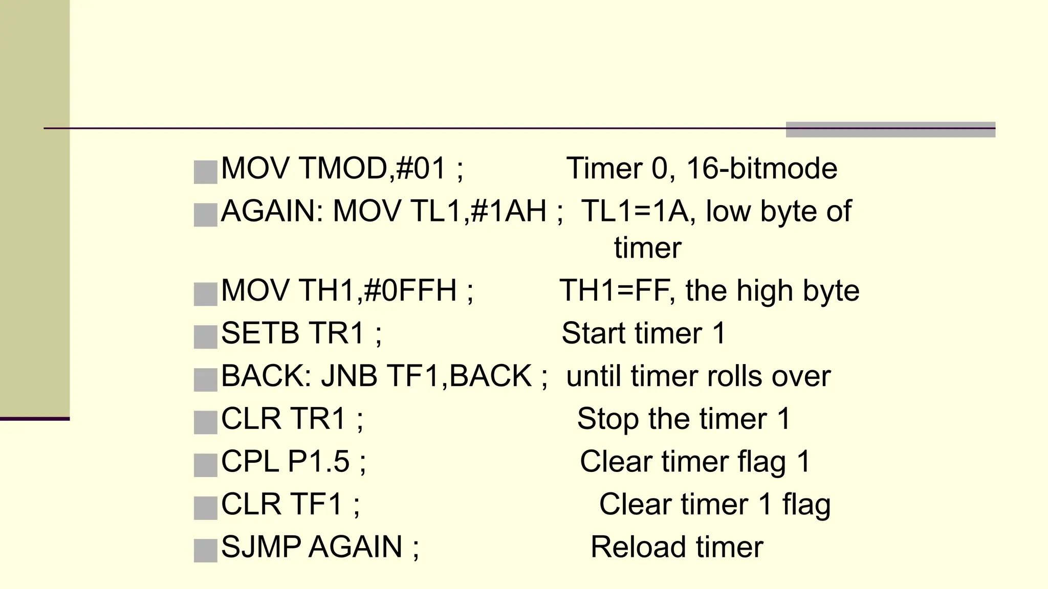
■MOV TMOD,#01 ;Timer 0, 16-bitmode ■AGAIN: MOV TL1,#1AH ; TL1=1A, low byte of timer ■MOV TH1,#0FFH ; TH1=FF, the high byte ■SETB TR1 ; Start timer 1 ■BACK: JNB TF1,BACK ; until timer rolls over ■CLR TR1 ; Stop the timer 1 ■CPL P1.5 ; Clear timer flag 1 ■CLR TF1 ; Clear timer 1 flag ■SJMP AGAIN ; Reload timer
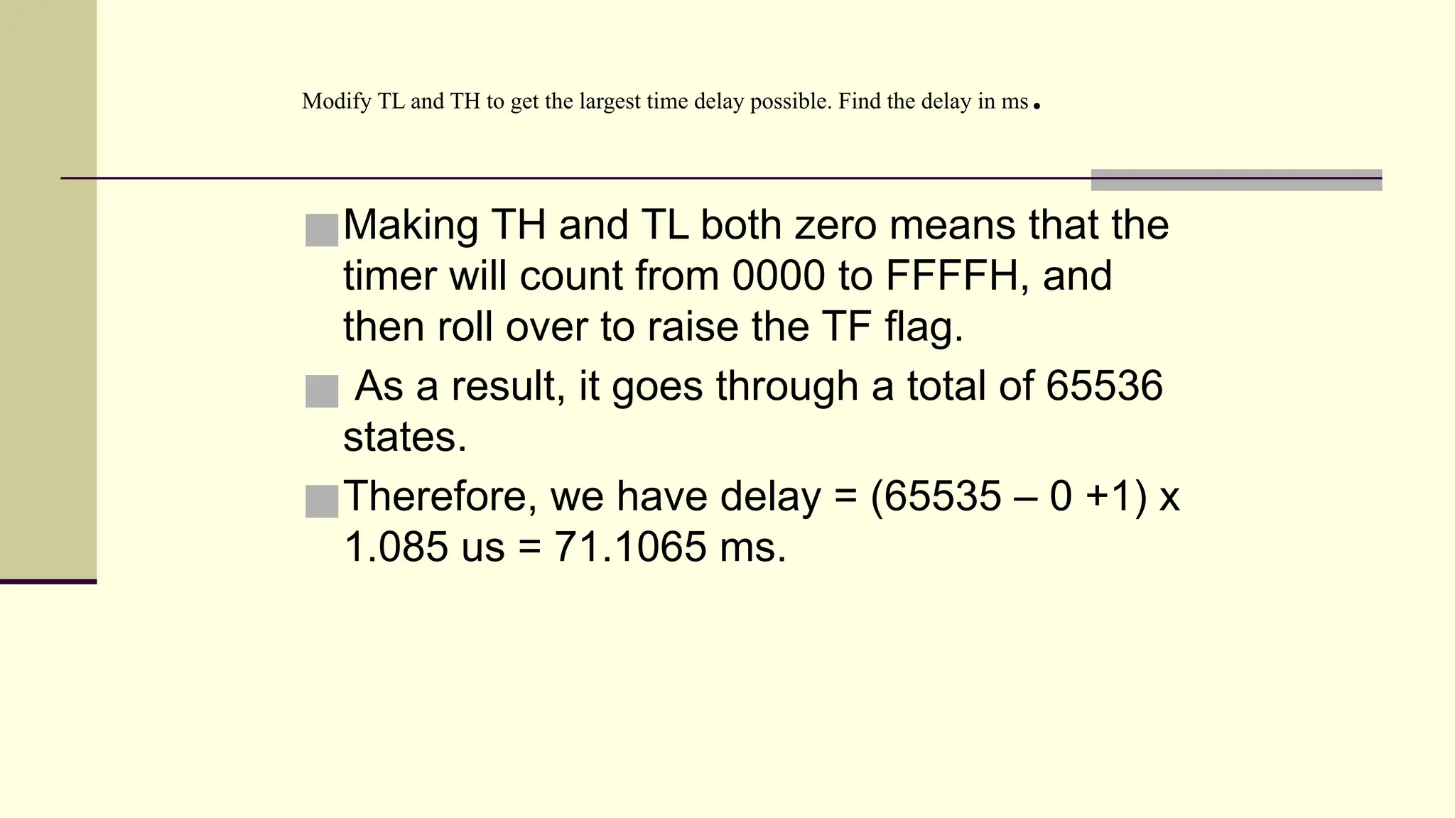
■Making TH andTL both zero means that the timer will count from 0000 to FFFFH, and then roll over to raise the TF flag. ■ As a result, it goes through a total of 65536 states. ■Therefore, we have delay = (65535 – 0 +1) x 1.085 us = 71.1065 ms. Modify TL and TH to get the largest time delay possible. Find the delay in ms.
40.
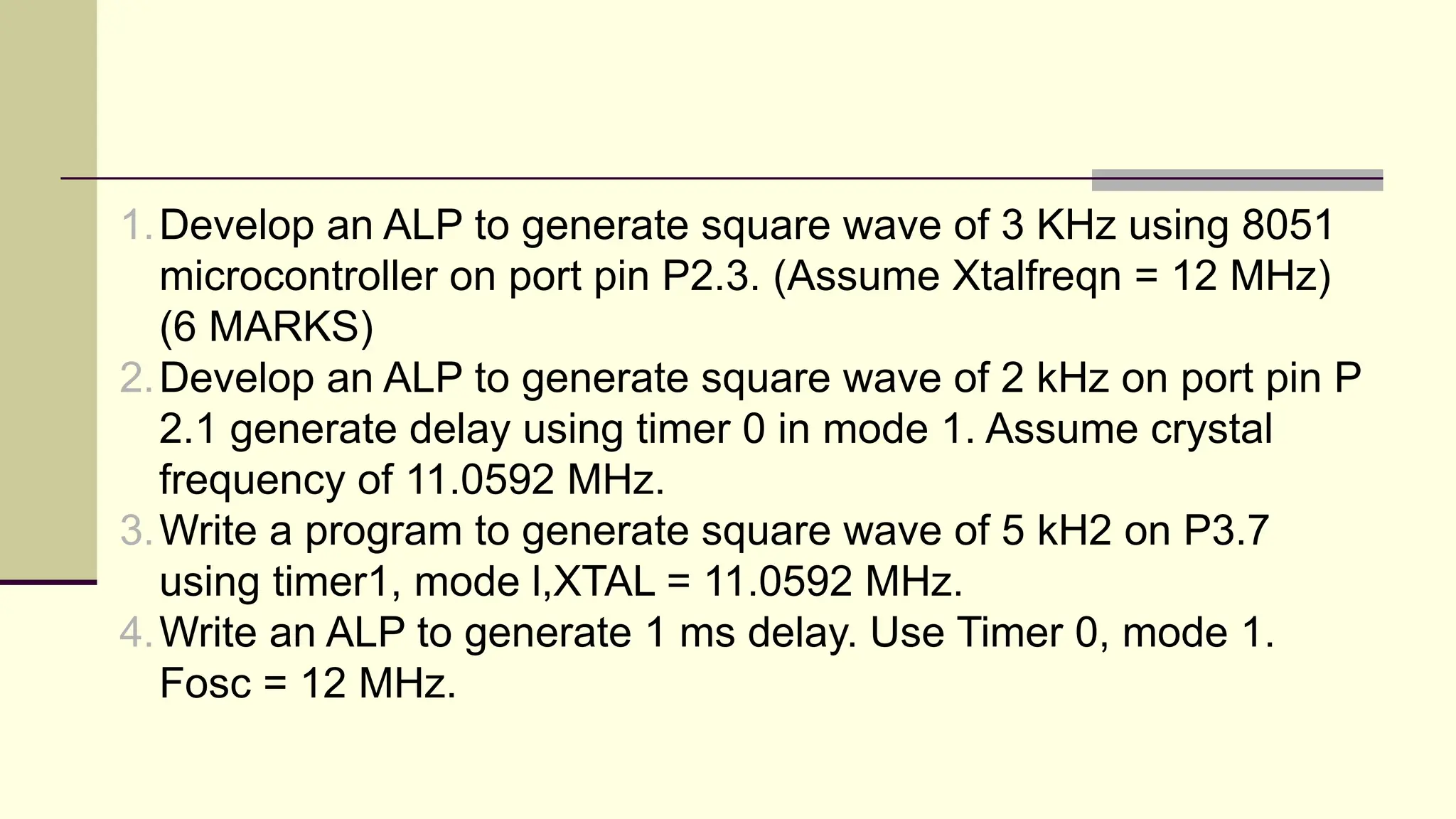
1.Develop an ALPto generate square wave of 3 KHz using 8051 microcontroller on port pin P2.3. (Assume Xtalfreqn = 12 MHz) (6 MARKS) 2.Develop an ALP to generate square wave of 2 kHz on port pin P 2.1 generate delay using timer 0 in mode 1. Assume crystal frequency of 11.0592 MHz. 3.Write a program to generate square wave of 5 kH2 on P3.7 using timer1, mode l,XTAL = 11.0592 MHz. 4.Write an ALP to generate 1 ms delay. Use Timer 0, mode 1. Fosc = 12 MHz.
43.
Mode 2 ■ Itis an 8-bit timer; therefore, it allows only values of 00 to FFH to be loaded into the timer’s register TH. ■ After TH is loaded with the 8-bit value, the 8051 gives a copy of it to TL. Then the timer must be started. This is done by the instruction “SETB TRO” for Timer 0 and “SETB TR11 ‘ for Timer 1. ■ After the timer is started, it starts to count up by incrementing the TL register. It counts up until it reaches its limit of FFH. When it rolls over from FFH to 00, it sets high the TF (timer flag). If we are using Timer 0, TFO goes high; if we are using Timer 1, TF1 is raised.
44.
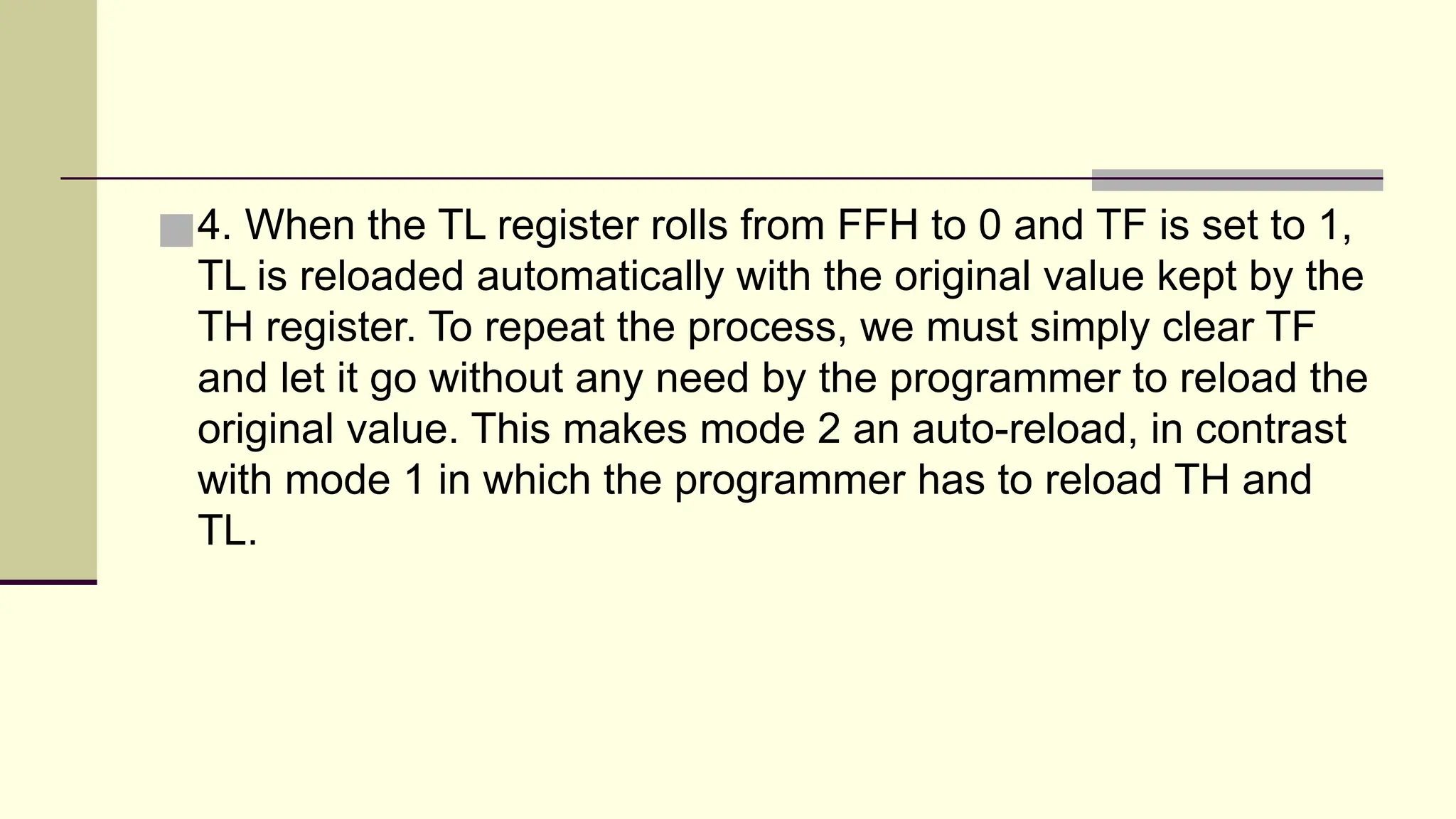
■4. When theTL register rolls from FFH to 0 and TF is set to 1, TL is reloaded automatically with the original value kept by the TH register. To repeat the process, we must simply clear TF and let it go without any need by the programmer to reload the original value. This makes mode 2 an auto-reload, in contrast with mode 1 in which the programmer has to reload TH and TL.
45.
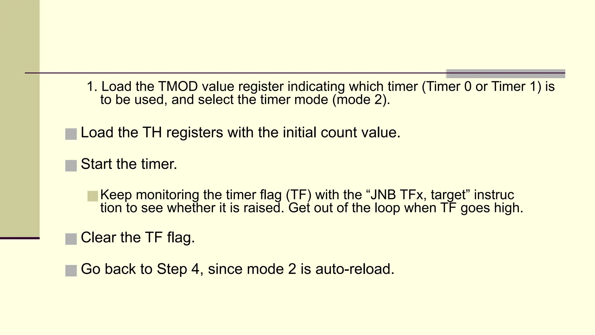
1. Load theTMOD value register indicating which timer (Timer 0 or Timer 1) is to be used, and select the timer mode (mode 2). ■ Load the TH registers with the initial count value. ■ Start the timer. ■Keep monitoring the timer flag (TF) with the “JNB TFx, target” instruc tion to see whether it is raised. Get out of the loop when TF goes high. ■ Clear the TF flag. ■ Go back to Step 4, since mode 2 is auto-reload.
46.
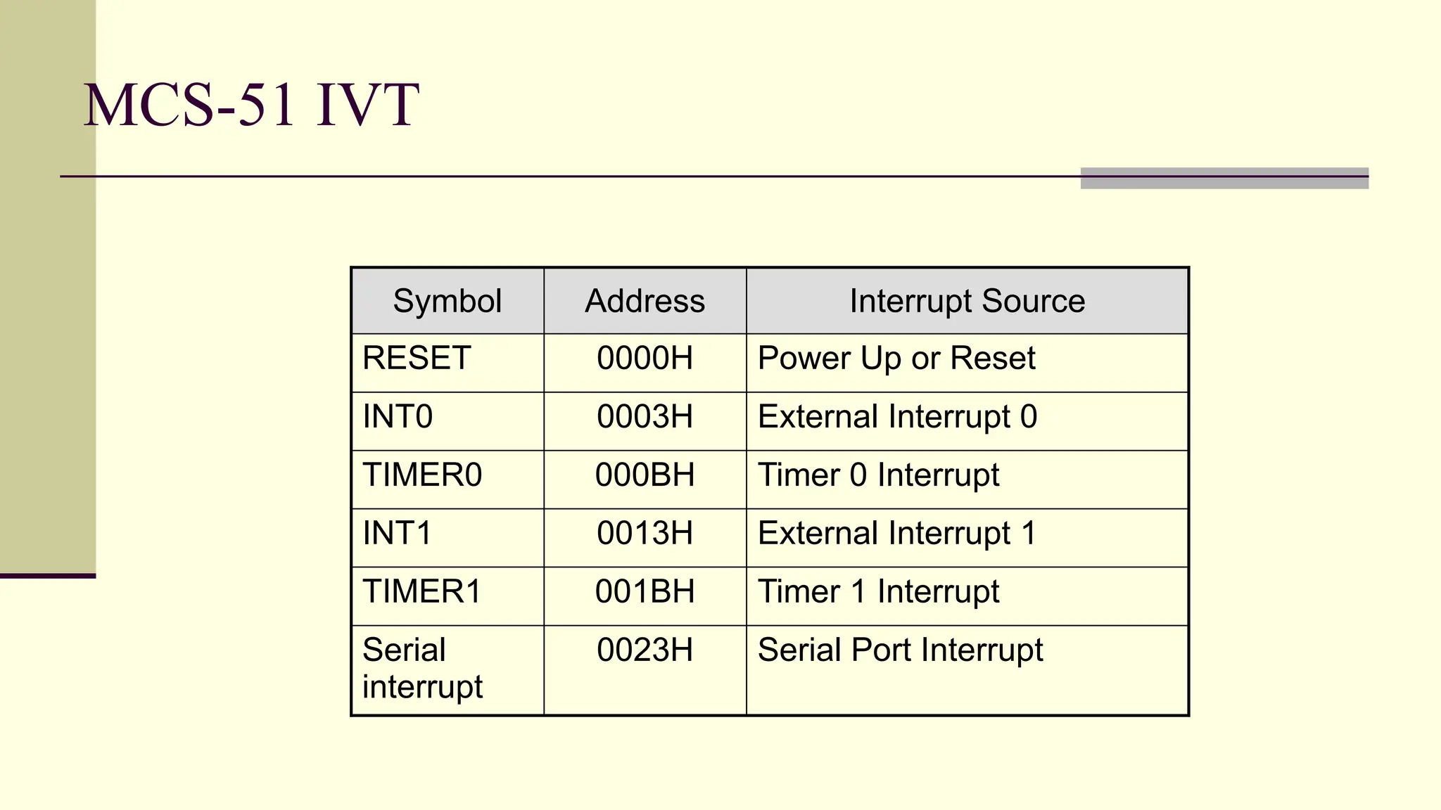
MCS-51 IVT Symbol AddressInterrupt Source RESET 0000H Power Up or Reset INT0 0003H External Interrupt 0 TIMER0 000BH Timer 0 Interrupt INT1 0013H External Interrupt 1 TIMER1 001BH Timer 1 Interrupt Serial interrupt 0023H Serial Port Interrupt
47.
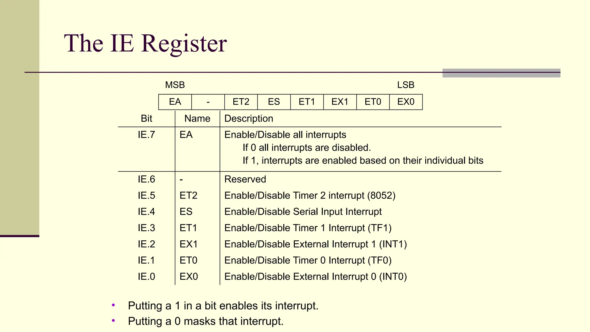
The IE Register MSBLSB EA - ET2 ES ET1 EX1 ET0 EX0 Bit Name Description IE.7 EA Enable/Disable all interrupts If 0 all interrupts are disabled. If 1, interrupts are enabled based on their individual bits IE.6 - Reserved IE.5 ET2 Enable/Disable Timer 2 interrupt (8052) IE.4 ES Enable/Disable Serial Input Interrupt IE.3 ET1 Enable/Disable Timer 1 Interrupt (TF1) IE.2 EX1 Enable/Disable External Interrupt 1 (INT1) IE.1 ET0 Enable/Disable Timer 0 Interrupt (TF0) IE.0 EX0 Enable/Disable External Interrupt 0 (INT0) • Putting a 1 in a bit enables its interrupt. • Putting a 0 masks that interrupt.
48.
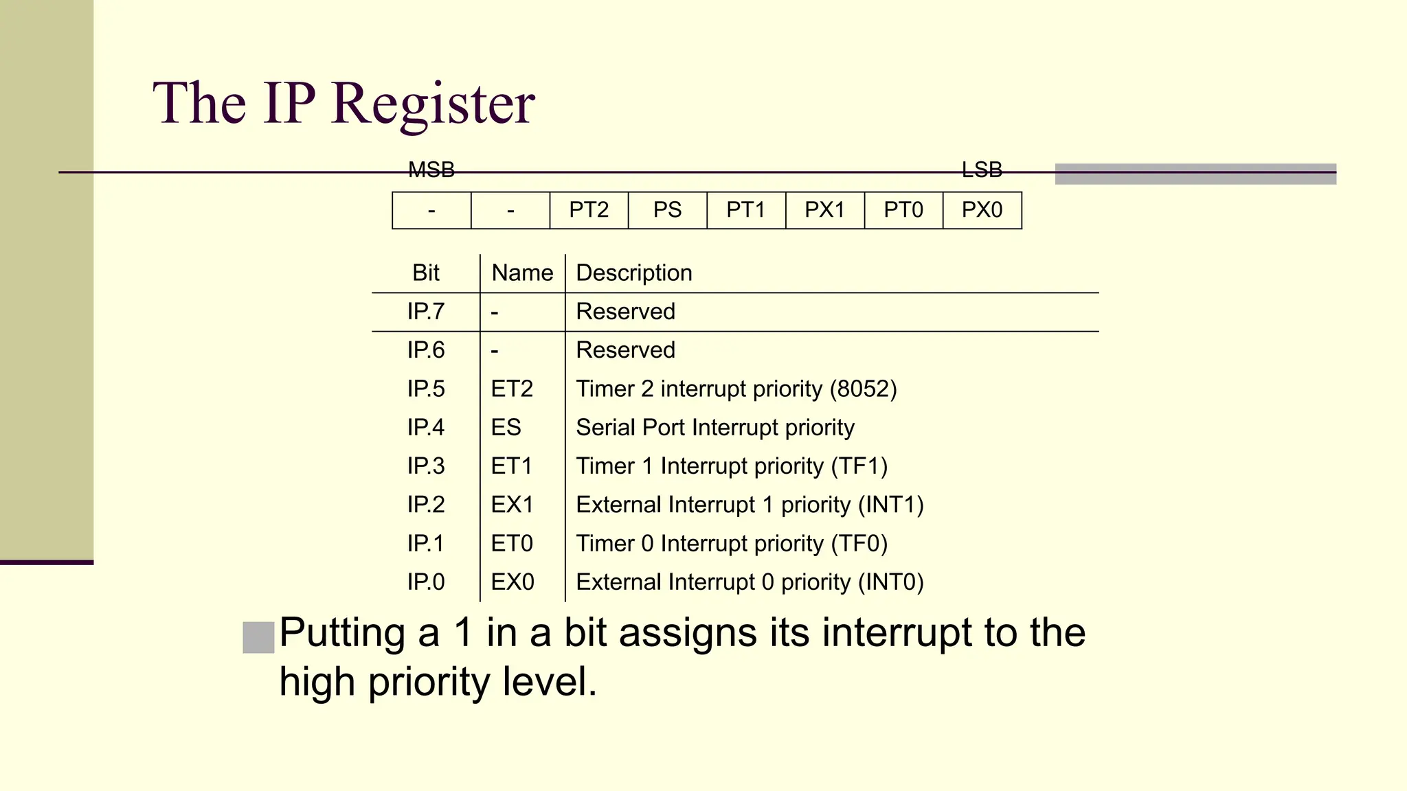
The IP Register ■Puttinga 1 in a bit assigns its interrupt to the high priority level. MSB LSB - - PT2 PS PT1 PX1 PT0 PX0 Bit Name Description IP.7 - Reserved IP.6 - Reserved IP.5 ET2 Timer 2 interrupt priority (8052) IP.4 ES Serial Port Interrupt priority IP.3 ET1 Timer 1 Interrupt priority (TF1) IP.2 EX1 External Interrupt 1 priority (INT1) IP.1 ET0 Timer 0 Interrupt priority (TF0) IP.0 EX0 External Interrupt 0 priority (INT0)
49.
Timer Control Register ■The TCON register (88H) contains status and control bits for Timer0 and Timer1. ■ Bit addressable. MSB LSB TF1 TR1 TF0 TR0 IE1 IT1 IE0 IT0 Bit Name Description TCON.7 TF1 Timer 1 overflow flag TCON.6 TR1 Timer 1 run-control bit. Used to turn the timer on/off TCON.5 TF0 Timer 0 overflow flag TCON.4 TR0 Timer 0 run-control bit. TCON.3 IE1 External Interrupt 1 edge flag TCON.2 IT1 External Interrupt 1 type flag TCON.1 IE0 External Interrupt 0 edge flag TCON.0 IT0 External Interrupt 0 type flag
50.
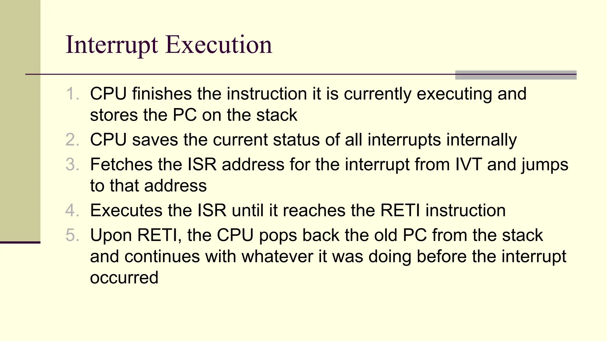
Interrupt Execution 1. CPUfinishes the instruction it is currently executing and stores the PC on the stack 2. CPU saves the current status of all interrupts internally 3. Fetches the ISR address for the interrupt from IVT and jumps to that address 4. Executes the ISR until it reaches the RETI instruction 5. Upon RETI, the CPU pops back the old PC from the stack and continues with whatever it was doing before the interrupt occurred