Downloaded 455 times
![ASSEMBLING AND RUNNING AN 8051 PROGRAM R.K.Tiwari(ravikumar.tiwari@raisoni.net) An Assembly language instruction consists of four fields: [label : ] mnemonic [operands] [;comment]](https://image.slidesharecdn.com/unit-ilecture4-150619055923-lva1-app6891/75/8051-Assembly-Language-Programming-6-2048.jpg)
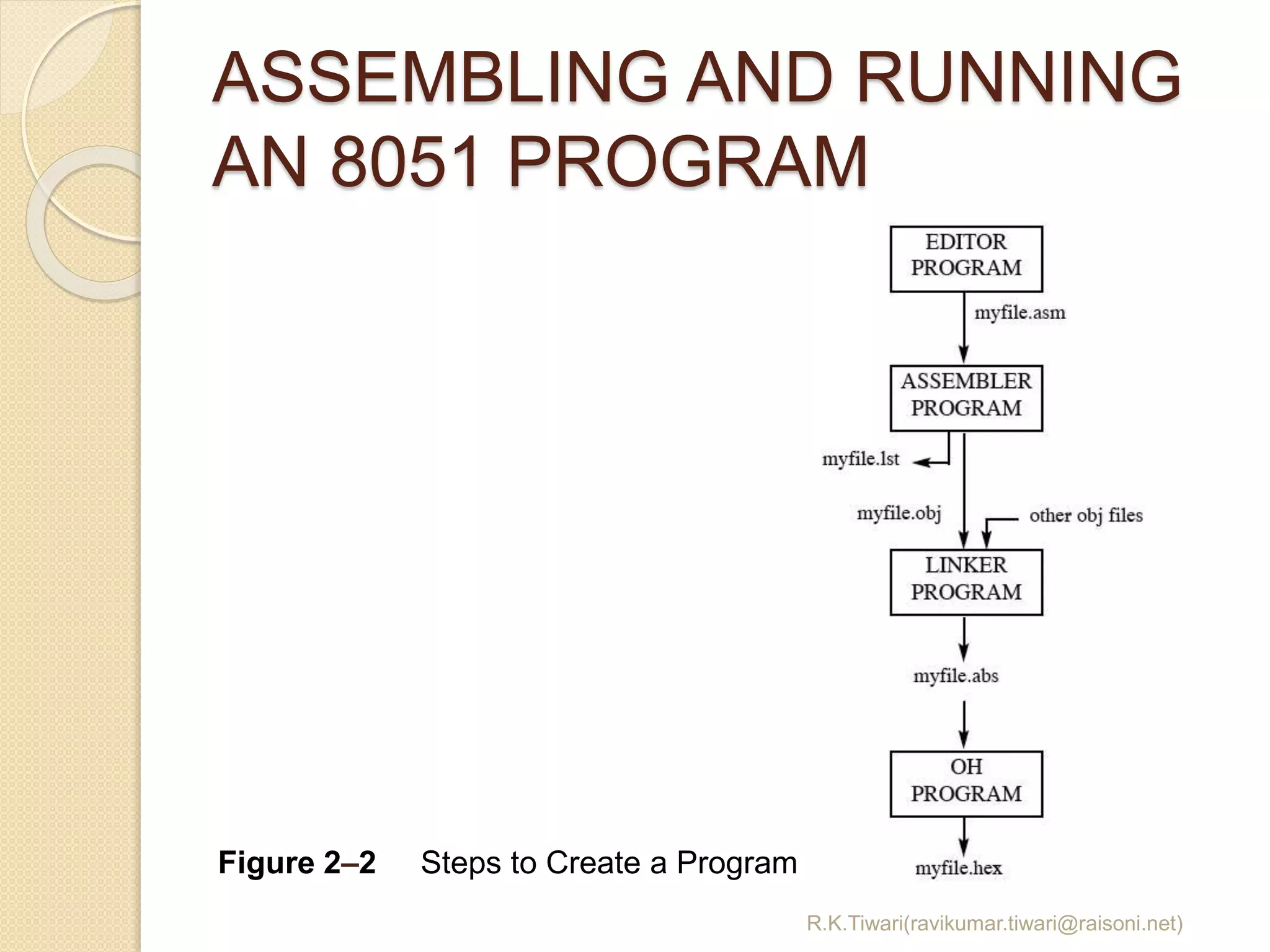
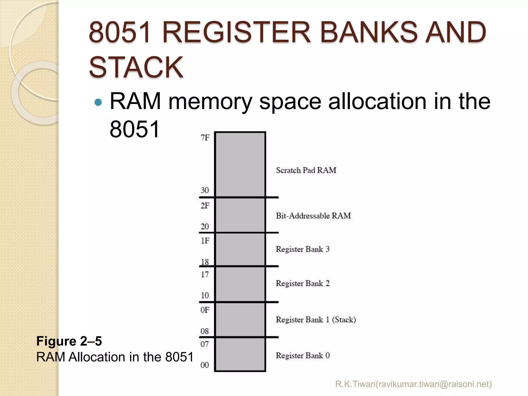
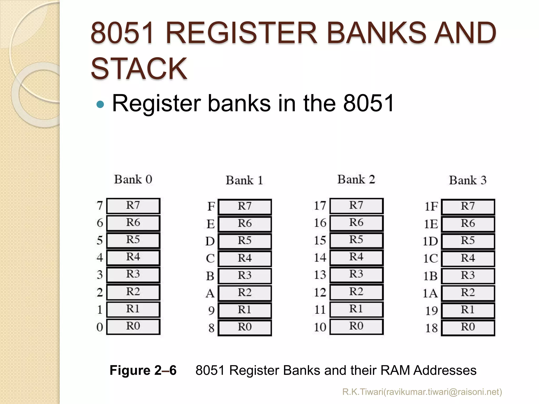

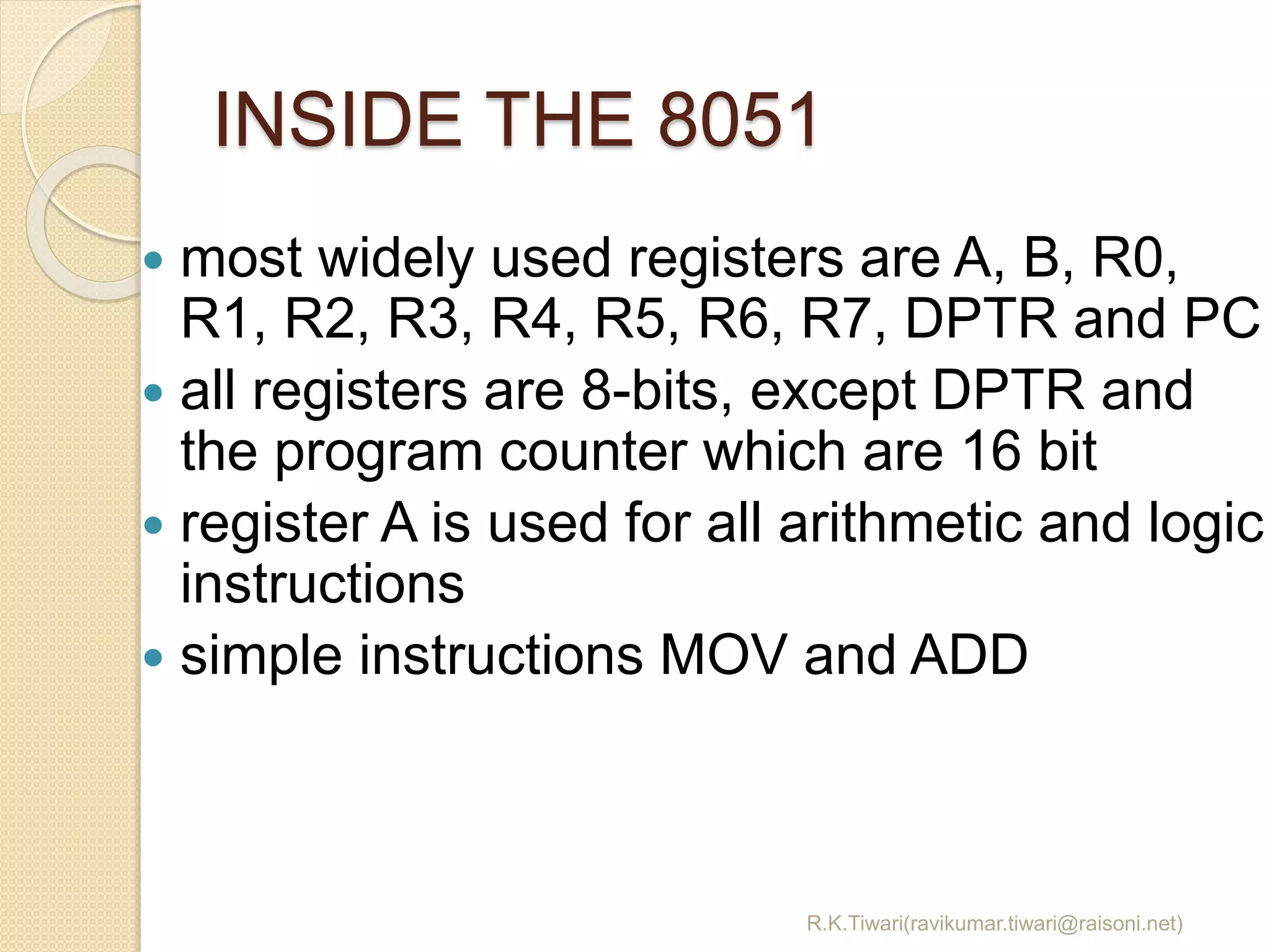
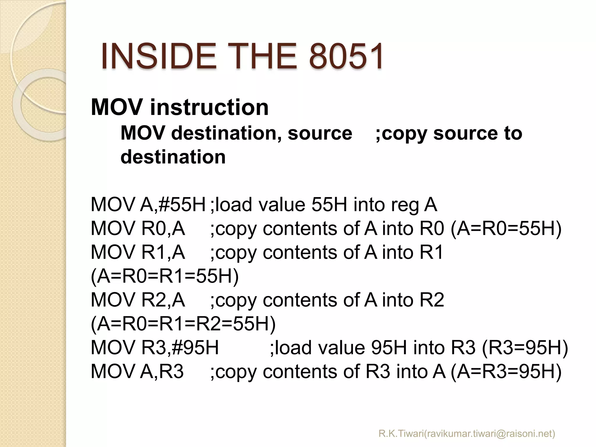
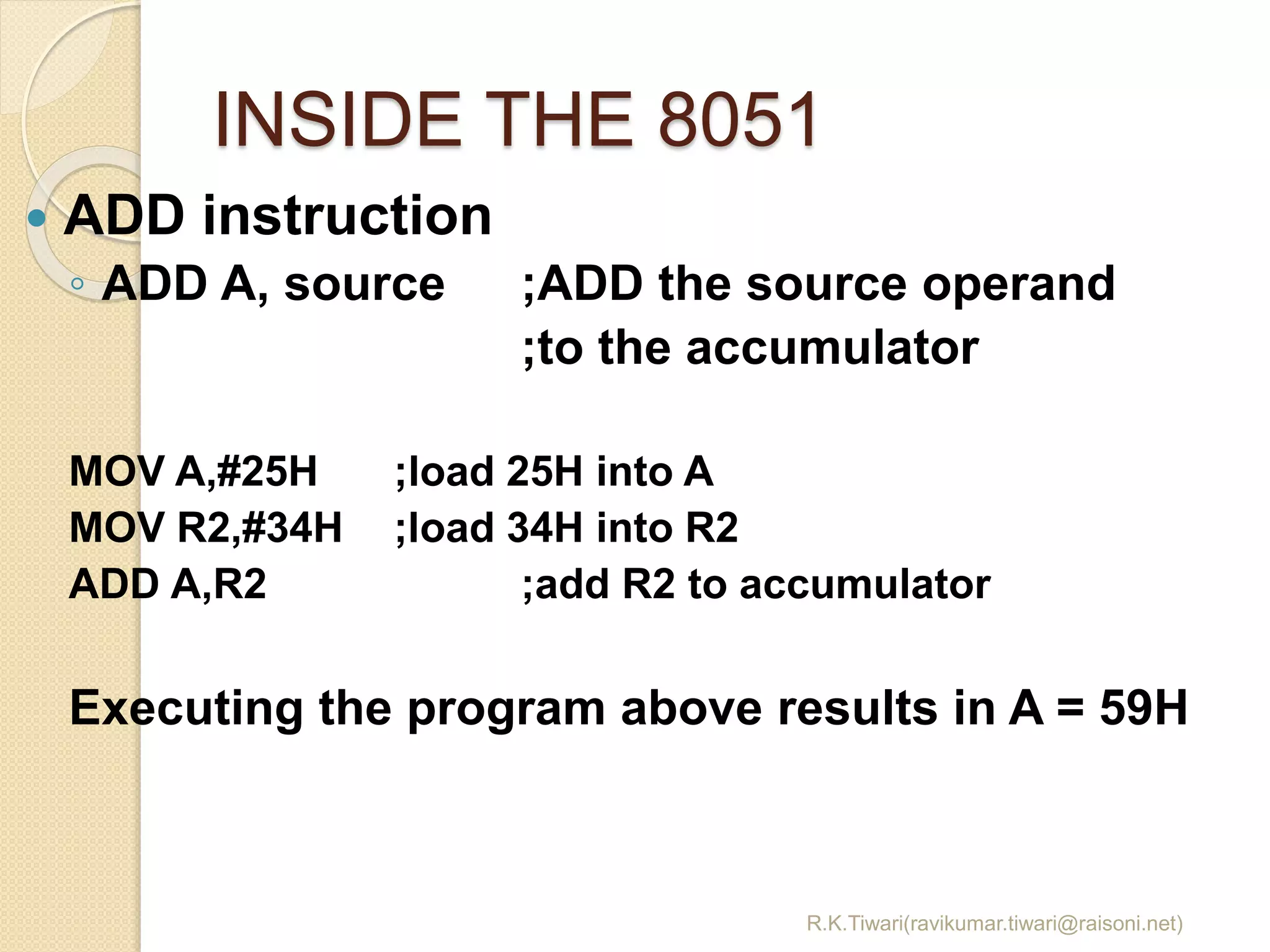
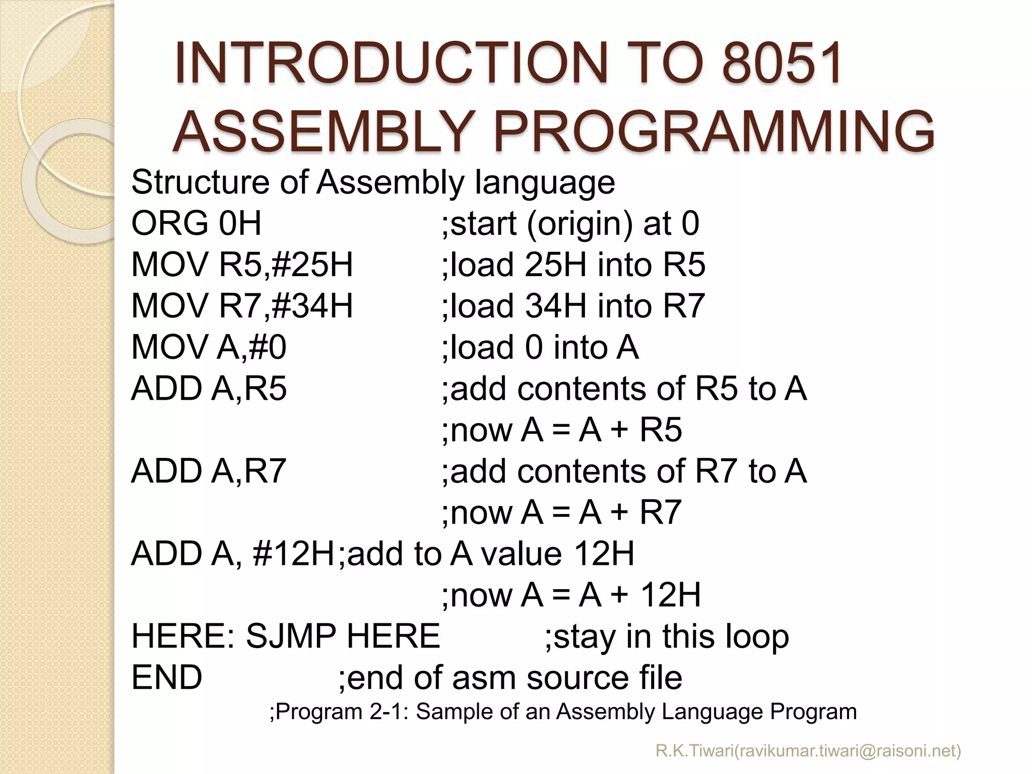
The document discusses various aspects of 8051 assembly language programming including: - The most commonly used 8-bit registers in the 8051 and the 16-bit program counter and data pointer registers. - Examples of MOV and ADD instructions to move data between registers and perform arithmetic operations in the accumulator register. - The steps required to assemble and run an 8051 program, including creating an assembly source file, assembling it to produce object and list files, and optionally linking files to run on a simulator. - Memory allocation and usage in the 8051 including the 64KB program memory space accessed by the 16-bit program counter and RAM allocation for registers and stack.