Arduino Quick Start
2. Devices & Examples
3. M5Unified
4. M5GFX
5. Extensions
Unit
Base
Cap
IoT
Unit ACSSR/DCSSR Arduino Tutorial
1. Preparation
1.Environment configuration: Refer to the Arduino IDE Getting Started Tutorial to complete the IDE installation, and install the corresponding board manager and required driver libraries according to the development board actually used.
2.Driver libraries used:
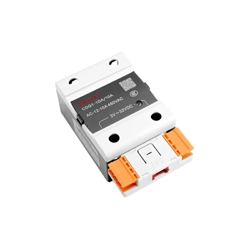
3.Hardware products used:

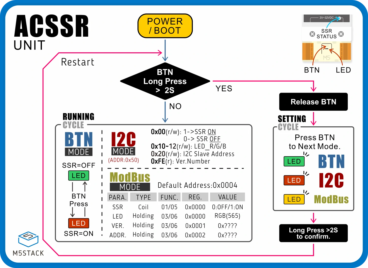
2. Working Mode
- 1.With the device powered off, press and hold the middle button.
- 2.Power on the device. When the device RGB LED flashes rapidly, it indicates it has entered mode configuration state.
- 3.Click the button to switch modes:
- Green light: Manual button mode. During operation, use the middle button to control the switch.
- Red light: I2C communication mode. During operation, connect to the I2C bus via the HY2.0-4P Grove interface for control.
- Yellow light: Modbus communication mode. During operation, connect to the Modbus bus via the VH3.96-4P interfaces on both ends of the device for control.
- 4.Press and hold the button to select and save the current mode.
- Load wiring sample diagram

3. I2C Mode Control
After configuring the device into I2C working mode, connect it to the I2C bus via the HY2.0-4P Grove interface for control. In this example, CoreS3 PORT.A is used for communication. When pairing with other controllers, please modify the program according to the actual connected pins.
#include "M5Unified.h" #include "M5_ACSSR.h" M5_ACSSR SSR; void printStatus(); void setup() { M5.begin(); Serial.begin(115200); while (!SSR.begin(&Wire, 2, 1, ACSSR_DEFAULT_ADDR)) { M5.Display.println("ACSSR I2C INIT ERROR"); Serial.println("ACSSR I2C INIT ERROR"); delay(1000); } M5.Display.setFont(&fonts::FreeMonoBold12pt7b); } void loop() { SSR.on(); SSR.setLEDColor(0xff0000); printStatus(); delay(1000); SSR.off(); SSR.setLEDColor(0x00ff00); printStatus(); delay(1000); } void printStatus() { int relay = SSR.status(); int color = SSR.getLEDColor(); int version = SSR.getVersion(); M5.Display.clear(); M5.Display.setCursor(0, 0); M5.Display.println("I2C Mode Control"); if (relay != -1) { Serial.printf("Relay: %s\n", relay ? "ON" : "OFF"); M5.Display.printf("Relay: %s\n", relay ? "ON" : "OFF"); } if (color != -1) { Serial.printf("LED Color: 0x%04X\n", color); M5.Display.printf("LED Color: 0x%04X\n", color); } if (version != -1) { Serial.printf("FW Version: 0x%04X\n", version); M5.Display.printf("FW Version: 0x%04X\n", version); } }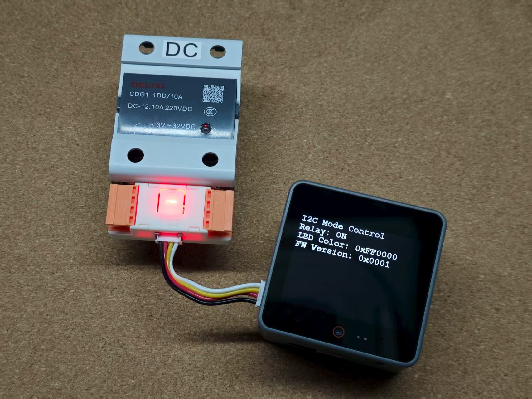
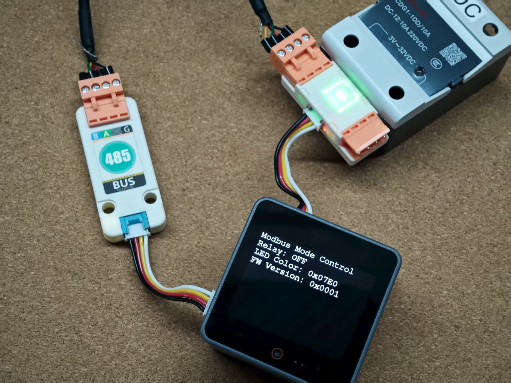
4. Modbus Mode Control
After configuring the device into Modbus working mode, connect it to the Modbus bus via the VH3.96-4P interfaces on both ends of the device for control. In this example, CoreS3 PORT.A with Unit RS485-ISO is used for RS485 communication.
#include "M5Unified.h" #include "M5_ACSSR.h" #include <ArduinoModbus.h> #include <ArduinoRS485.h> RS485Class RS485(Serial2, 1, 2, -1, -1); uint8_t slave_id = 0; void relayOn(); void relayOff(); void setLedColor(uint16_t color); int getRelayStatus(); int getLedColor(); int getFirmwareVersion(); void printStatus(); void setup() { M5.begin(); Serial.begin(115200); delay(2000); Wire.end(); ModbusRTUClient.begin(115200, SERIAL_8N1); slave_id = ACSSR_DEFAULT_SLAVE_ID; M5.Display.setFont(&fonts::FreeMonoBold12pt7b); } void loop() { relayOn(); setLedColor(0xF800); // RED printStatus(); delay(1000); relayOff(); setLedColor(0x07E0); // GREEN printStatus(); delay(1000); } void relayOn() { ModbusRTUClient.coilWrite(slave_id, ACSSR_RELAY_COIL_ADDR, 0xFF); } void relayOff() { ModbusRTUClient.coilWrite(slave_id, ACSSR_RELAY_COIL_ADDR, 0x00); } void setLedColor(uint16_t color) { ModbusRTUClient.holdingRegisterWrite(slave_id, ACSSR_LED_HOLDING_ADDR, color); } int getRelayStatus() { if (ModbusRTUClient.requestFrom(slave_id, COILS, ACSSR_RELAY_COIL_ADDR, 1)) { while (ModbusRTUClient.available()) { return ModbusRTUClient.read(); } } return -1; } int getLedColor() { if (ModbusRTUClient.requestFrom(slave_id, HOLDING_REGISTERS, ACSSR_LED_HOLDING_ADDR, 1)) { while (ModbusRTUClient.available()) { return ModbusRTUClient.read(); } } return -1; } int getFirmwareVersion() { if (ModbusRTUClient.requestFrom(slave_id, HOLDING_REGISTERS, ACSSR_VERSION_HOLDING_ADDR, 1)) { while (ModbusRTUClient.available()) { return ModbusRTUClient.read(); } } return -1; } void printStatus() { int relay = getRelayStatus(); int color = getLedColor(); int version = getFirmwareVersion(); M5.Display.clear(); M5.Display.setCursor(0, 0); M5.Display.println("Modbus Mode Control"); if (relay != -1) { Serial.printf("Relay: %s\n", relay ? "ON" : "OFF"); M5.Display.printf("Relay: %s\n", relay ? "ON" : "OFF"); } if (color != -1) { Serial.printf("LED Color: 0x%04X\n", color); M5.Display.printf("LED Color: 0x%04X\n", color); } if (version != -1) { Serial.printf("FW Version: 0x%04X\n", version); M5.Display.printf("FW Version: 0x%04X\n", version); } }