Downloaded 22 times
![B Ravi Kumar et al. Int. Journal of Engineering Research and Applications www.ijera.com ISSN : 2248-9622, Vol. 5, Issue 5, ( Part -4) May 2015, pp.42-47 www.ijera.com 42 | P a g e Tuning PID Controller Parameters for Load Frequency Control Considering System Uncertainties B.RaviKumar1 , G.Ashok2 , B.SivaPrasad3 Asst.prof, AITAM, Tekkali Asst. prof, AITAM, Tekkali Asst.prof, AITAM, Tekkali. Abstract In this paper, parameters of PID controller and bias coefficient for Load Frequency Control (LFC) are designed using a new approach. In the proposed method, the power system uncertainties and nonlinear limitations of governors and turbines ,i.e. Valve Speed Limit (VSL)and Generation Rate Constraint (GRC), are taken into account in designing. Variations of uncertain parameters are considered between -40% and +40% of nominal values with 5% step .In order to design the proposed PID controller ,a new objective function is defined. MATLAB codes are developed for GA based PID controller tuning, the results of which are used to study the system step response. All these are through in Simulink based background. Keywords: Load frequency control; PID controller; ACE; Power system control; genetic algorithm I. INTRODUCTION The Load Frequency Control (LFC) system should maintain the system frequency and the inter- are a tie-line power flow close to the scheduled values[1,2].The conventional design method of LFC is based on the power system linear model with fixed parameters. The optimal control theory has been proposed in[2]andutilizedsinceearly1970s.ThePID controller is used here to nullify the effect of frequency and tie-line power deviations in both the areas. MATLAB code has been developed to achieve PID controller tuning based on genetic algorithm. PID controller tuning ensures the improvements in the system response in terms of settling time ,rise time, overshoot and steady state value. Studies are made for different contract conditions. The results are compared with step response of similar system having a PID controller tuned with PSO in conventional interconnected power system [14] without deregulation. The results obtained for the problem in hand provide interesting load control scenario in comparison to the conventional situation. The block diagram s of two area load frequency control under deregulation and conventional scenario are drawn in simulink and the overall system response is found for change of load in one area. II. SYSTEM AND UNCERTAINTIES MODELING There are various complicated non linear models for large power systems, but linearized model has been usually used [1,2].InFig.1,atwo-area power system is shown In this paper, this system is studied and the errors of the linearization are considered as Parametric uncertainties and un-modeled dynamics. Each are a consists of three first-order transfer functions ,modeling the turbine ,governor and power system .In addition ,all generators in each area are assumed to form a coherent group. The transfer function of PID controller in each area is considered as follow: The PID controllers are widely utilized in industries. In the industrial PID controllers, Low Pass Filter(LPF) is used in order to remove high frequency noise. Therefore, the transfer function of derivative of the PID controller has been replaced by kds/(1+Tds) (where kd<Td)[6]. In previous researches, different saturation limits have been considered for governor and turbine[9- 11].In this paper, two saturation limits ,i.e. .VSL and GRCareconsidered.Fig.2showsthe governor and turbine linear model and their VSL and GRC ,respectively. ∆PV and ∆PT are the deviations of governor position and deviations of turbine power respect to the nominal values, respectively. RESEARCH ARTICLE OPEN ACCESS](https://image.slidesharecdn.com/h55044247-150528093211-lva1-app6891/75/Tuning-PID-Controller-Parameters-for-Load-Frequency-Control-Considering-System-Uncertainties-1-2048.jpg)
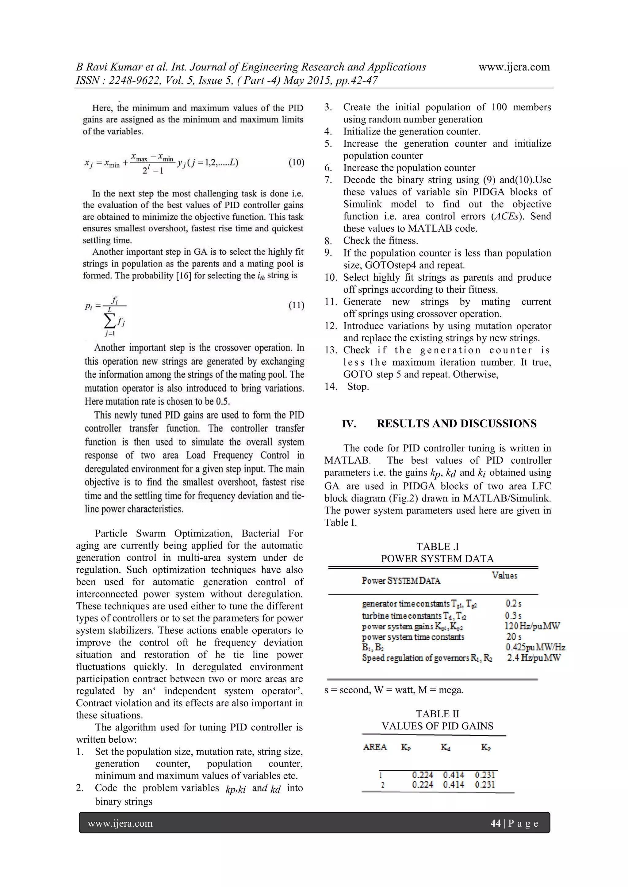
![B Ravi Kumar et al. Int. Journal of Engineering Research and Applications www.ijera.com ISSN : 2248-9622, Vol. 5, Issue 5, ( Part -4) May 2015, pp.42-47 www.ijera.com 43 | P a g e III. OBJECTIVE FUNCTION CONSIDERING UNCERTAINTIES In this section, the objective function of the proposed PID due to load changes (∆PL) is presented. The objective function is based on ITAE expressed by the following equation In an N-area power system, the load disturbance (change) can affect the frequency of all areas. To design the load frequency controller, all inputs and outputs should be taken in to account .For PID controller; the objective function is defined as follows: the tie-line power deviation i.e .the difference between the scheduled power deviation (Ptie12sch) and the actual power deviation (Ptie12actual). The latter two are represented through(4)and(5). The PID controller design is The most important part of the Automatic Generation Control (AGC).The choice of proportional-integral-derivative(PID) controller than proportional plus integral (PI)controller ensures better system response in terms overshoot and settling time[15]. The ACE signals are controlled using the PID controller to produce control vectors for the AGC. In this work, the PID controller tuning is done through Genetic Algorithm (GA). The proportional (kp), integral (ki) and derivative (kd) gains are set using GA. The transfer function of the PID controller (6) used for both the areas are considered to be identical. To get the optimized values of the PID gains, suitable objective function is developed here. However the maximum and minimum values of the gains are appropriately chosen. This objective function (OB) can be defined as the sum of the squares of the area control errors (ACE1and ACE2) in each area as shown in (8). III. PID CONTROLLER PARAMETER TUNING USING GENETIC ALGORITHM A combination of Darwinian Survival of the fittest principle and genetic operation is popularly known as Genetic Algorithm. This became an effective method of optimization. To accommodate the entire range of possible solutions, larger value of population size(100) is chosen. The implementation of GA starts with parameter encoding [16].This is done with great care so that the link between the objective function and the strings are maintained properly.](https://image.slidesharecdn.com/h55044247-150528093211-lva1-app6891/75/Tuning-PID-Controller-Parameters-for-Load-Frequency-Control-Considering-System-Uncertainties-2-2048.jpg)
![B Ravi Kumar et al. Int. Journal of Engineering Research and Applications www.ijera.com ISSN : 2248-9622, Vol. 5, Issue 5, ( Part -4) May 2015, pp.42-47 www.ijera.com 45 | P a g e TABLE III PERFORMANCE STUDY The DISCOs of this problem take power from the GENCOs according to the DPM. Here it is assumed that the each element of DPM has a value of 0.5. At the same time each GENCO participates in automatic generation control according to the area participation factors apf1 =0.5 and apf2 = 0.5 Initially the system is run without the use of the controller due to the load change in area1 under deregulation. But it is found that the system is unstable. The tie line power deviation due to load change in area1 in two area load frequency control without controller is shown in Fig. 3. Hence with the application of PID controller the simulation is done again for the change of load in area1 by 0.1 pu in deregulated environment. The corresponding frequency deviations in area1 and area2 are shown in Fig. 4 and Fig. 5 respectively. The values of PID controller gains obtained through GA are shown in Table II. The tie line power deviation is depicted in Fig. 6. The two area power system without PIDGA was simulated initially and it showed unstable response. With the application of GA tuned PID controller, the system became stable. The system performances based on the settling time, rise time and % peak overshoot are shown in Table III. Fig. 3. Tie line power deviation (in pu) with respect to time (in sec) due to change in load of area1 without any PID controller. Fig. 4. Frequency deviation with respect to time (in sec) in area1 due to 0.1 pu load change in area1 Fig. 5. Frequency deviation (in pu) with respect to time (in sec) in area 2 due to 0.1 pu load change in area1 Fig. 6. Tie line power deviation (in pu ) with respect to time (in sec)due to change in load of area1 It is observed from Table III that peak overshoot is well below 25%, settling time and rise time are also within limits i.e. the steady state frequency is restored within 12 sec (approximately) after the sudden change of load in area1. The tie line power characteristics show that the 0.1 pu change of load in area 1 is shared by both the GENCOs as per the DPM matrix. It means that the 0.05 p.u load will be supplied. 1. An interconnected power system having same parameters that of the power system chosen here was simulated using PSO based PID controller under deregulation in another work [14]. A comparison of the frequency deviation characteristics of these two worksreveals that the numbers of oscillations have been](https://image.slidesharecdn.com/h55044247-150528093211-lva1-app6891/75/Tuning-PID-Controller-Parameters-for-Load-Frequency-Control-Considering-System-Uncertainties-4-2048.jpg)
![B Ravi Kumar et al. Int. Journal of Engineering Research and Applications www.ijera.com ISSN : 2248-9622, Vol. 5, Issue 5, ( Part -4) May 2015, pp.42-47 www.ijera.com 46 | P a g e reduced in case of PIDGA (Fig.3 and 4) in deregulated environment. Fig. 7. Tie line power error i.e. Ptie12error (in pu) with respect to time (in s) due to 0.1 pu change in load of area1 without deregulation Fig. 8. Tie line power deviation (in pu) with respect to time (in sec) due to 0.1 pu change in load of area1 without deregulation Fig. 7 shows the tie line power error i.e. Ptie12error versus time. It is clear from the plot that the steady state value of tie line power error is zero and its settling time is less than 4 sec (2% basis). Fig. 8 depicts the tie line power deviation in two area load frequency control system without deregulation, the steady state value of which is zero. But the corresponding tie line power deviation plot with deregulation is smooth and has less oscillation than that without deregulation. V. CONCLUSION In this work, two area load frequency control is established under deregulation. The PID controller which is used to bring the system dynamics within comfortable limits is tuned with the help of genetic algorithm. With the variation of load in one area, the deregulated system response is better than the system without deregulation in terms of numbers of oscillations and at the same time the load change is accommodated of both the areas without overloading any one of them. REFERENCES: [1] A. G. Kagiannas, D. T. Askounis and J. Psarras “Power generation planning: from monopoly to competetion” Electrical Power and Energy Systems, vol. 26, pp. 413–421, November 2004. [2] J. Sadeh and E. Rakhshani, “Multi-Area load frequency control in a deregulated power system using optimal output feedback control”, 5 pp.1-6. [3] W. Tan, H. Zhang and M. Yu, “Decentraliszed load frequency control in deregulated environment”, Electrical Power and Energy Systems, vol. 41, pp. 16-26, March, 2012. [4] H. Sadat. (2002). Power System Analysis (2nd edition), TATA McGraw Hill, NewDelhi [5] V. Donde, M. A. Pai, and L. A. Hiskens, "Simulation and optimization in an AGC system after deregulation", IEEE Trans. on Power Systems, vol.l6, no. 3, pp. 481- 489, August 2001 [6] F. Liu, Y.H. Song, J. Ma, S. Mei and Q. Lu, “Optimal load- frequency control in restructured power systems,” IEE Proc.- Gener. Transm. Distrib., vol. 150, no. 1, January 2003. [7] E. Rakhshani & J. Sadeh, "Simulation of two- area AGC system in a competitive environment using reduced-order observer method", in Proc of IEEE conf, April 2008. [8] N. Sinha, Loi Lei Lai, and V.G Rao, "GA Optimized PID Controllers for Automatic Generation Control of Two Area Reheat Thermal Systems Under Deregulated Environment", in IEEE conference on Electrical utility DRPT , 2008, pp. 1186-1191. [9] J. Nanda, S. Mishra and Lalit Chandra Saikia, "Maiden Application of Bacterial Foraging Based Optimization Technique in Multi-area Automatic Generation Control", IEEE Transactions on Power Systems, vo1.24, no.2, pp. 602-609, May, 2009 [10] S. Debbarma and L. C. Saikia, “Bacterial Foraging Based FOPID Controller in AGC of an Interconnected Two-Area Reheat Thermal System Under Deregulated Environment”, in International Conference On Advances In Engineering, Science And Management (ICAESM-2012), March 30-31, 2012, pp. 303-08. [11] E. S. Ali, S. M. Abd-Elazim, “BFOA based design of PID controller for two area load frequency with nonlinearities”, Electrical Power and Energy Systems, vol. 51, pp. 224-231, April,2013. [12] R. K. Sahu, S. Panda, U. K. Rout “DE optimized parallel 2-DOF PID controller](https://image.slidesharecdn.com/h55044247-150528093211-lva1-app6891/75/Tuning-PID-Controller-Parameters-for-Load-Frequency-Control-Considering-System-Uncertainties-5-2048.jpg)
![B Ravi Kumar et al. Int. Journal of Engineering Research and Applications www.ijera.com ISSN : 2248-9622, Vol. 5, Issue 5, ( Part -4) May 2015, pp.42-47 www.ijera.com 47 | P a g e for load frequency control of power system with governor dead-band nonlinearity”, Electrical Power and Energy Systems, vol. 49, pp. 19-33, February, 2013. [13] D P Kothari and I J Nagrath, (2008), Power System Engineering (2nd edition) [14] A. M. Jadhav and K. Vadirajacharya, “Performance verification of PID controller in an interconnected power system using particle swarm optimization”, Energy Procedia, vol.14 pp 2075-2080 ,2012 [15] K. Ogata, (2010), Modern Control Engineering, (5th Edition), K. Ogata, (2010), Modern Control Engineering, (5th Edition), [16] K. Ogata, (2010), Modern Control Engineering, (5th Edition), K. Ogata, (2010), Modern Control Engineering, (5th Edition). [17] D. P. Kothari and J. S. Dhillon, (2011), Power System Optimization, (2nd Edition), PHI Learning Private Limited](https://image.slidesharecdn.com/h55044247-150528093211-lva1-app6891/75/Tuning-PID-Controller-Parameters-for-Load-Frequency-Control-Considering-System-Uncertainties-6-2048.jpg)

The paper presents a method for tuning PID controller parameters for load frequency control (LFC) in power systems under uncertainty using genetic algorithms. It emphasizes considering system uncertainties, such as governor and turbine limitations, for improved control and stability, especially under deregulated conditions. Simulations demonstrate that the GA-tuned PID controller outperforms conventional methods in terms of settling time and system stability in response to load changes.