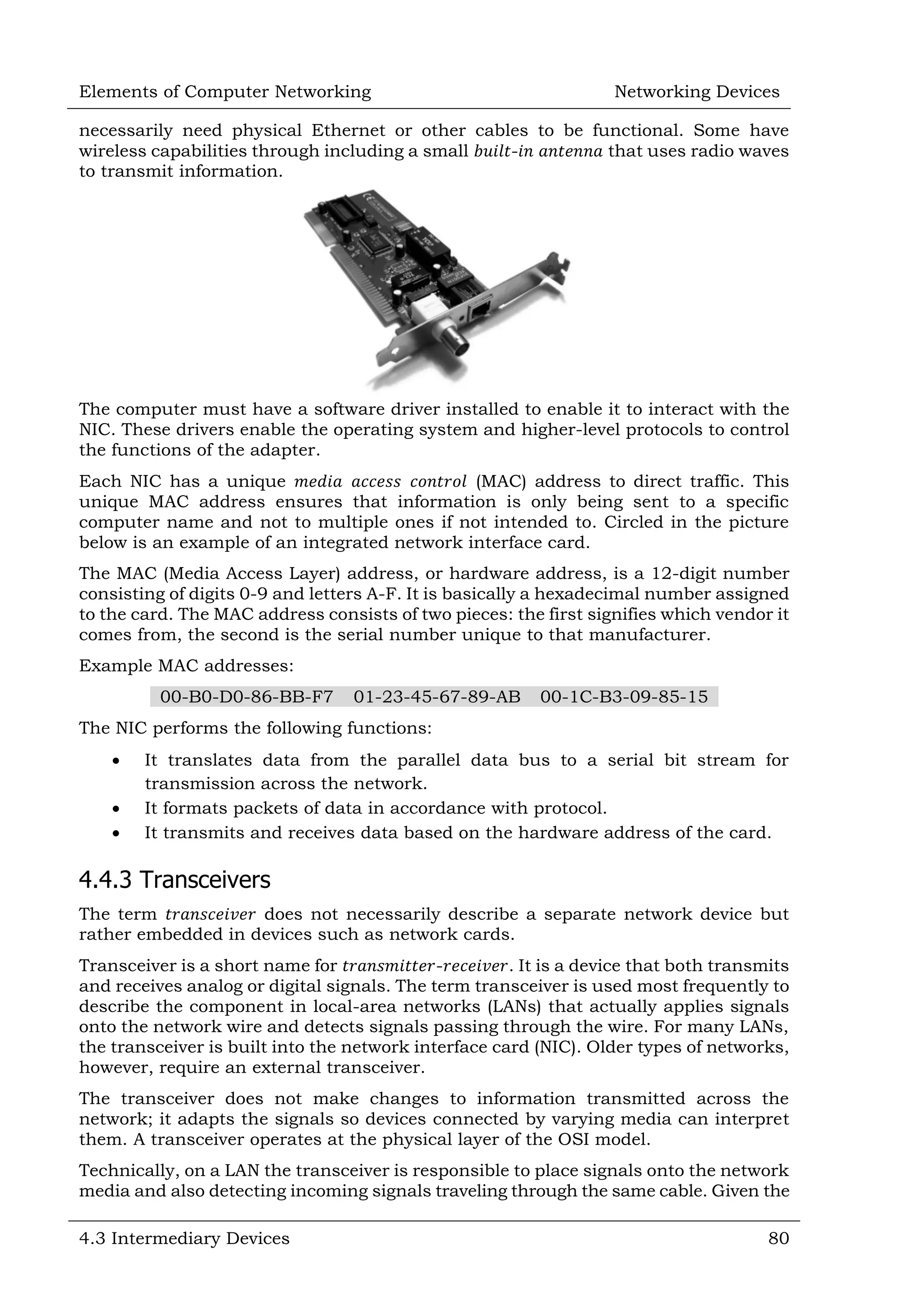
This document defines and describes various networking devices. It discusses connectivity devices like network interface cards (NICs) and transceivers that provide physical connections to networks but do not change data. It also mentions intermediary devices like routers, switches and hubs that direct and transmit data within networks or between multiple networks. The document provides examples of end devices directly used by people, like computers and printers, and discusses how intermediary devices work behind the scenes to ensure data flows across networks.
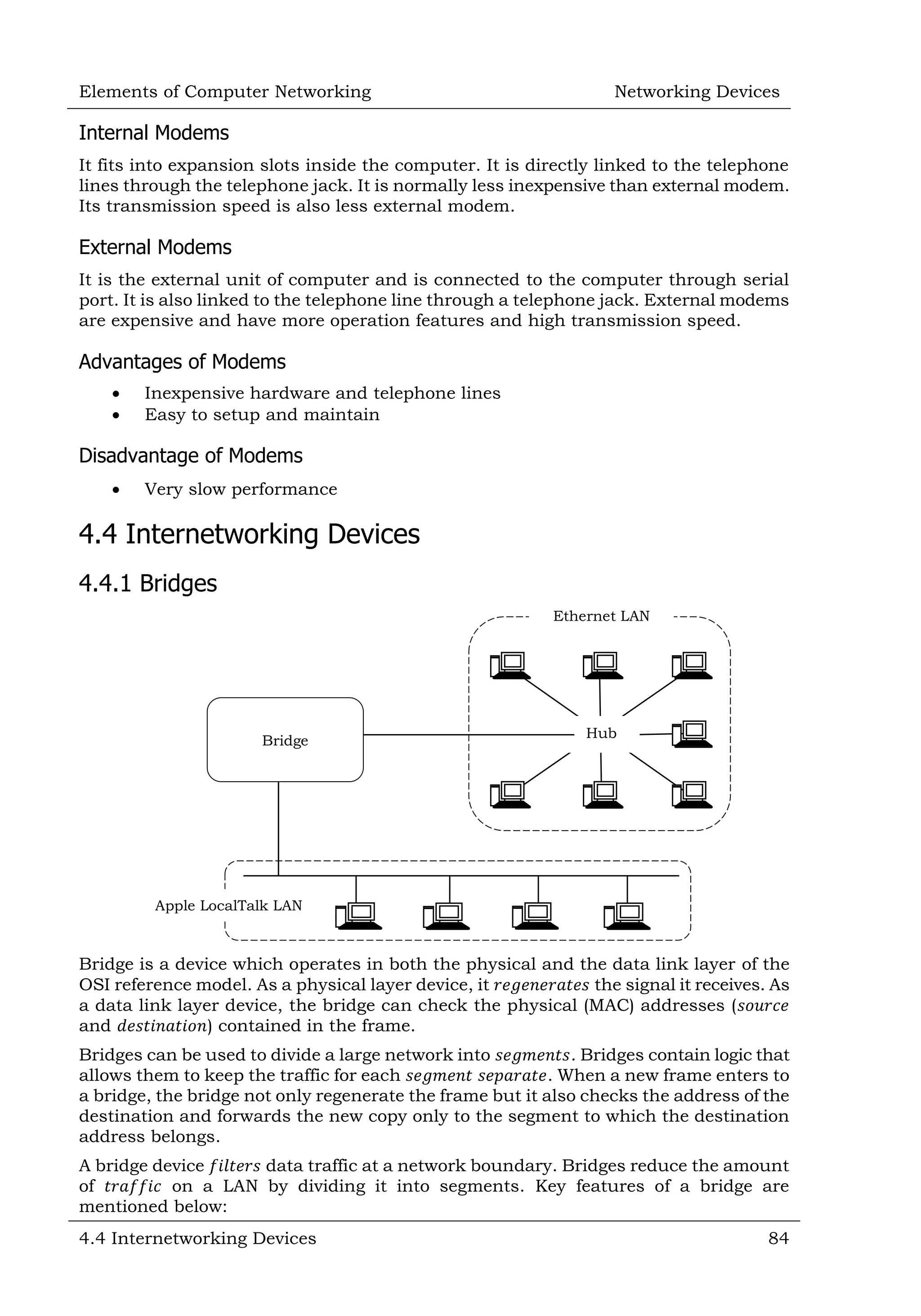
![Elements of Computer Networking Networking Devices 4.4 Internetworking Devices 85 A bridge operates both in physical and data-link layer A bridge uses a table for 𝑓𝑖𝑙𝑡𝑒𝑟𝑖𝑛𝑔/𝑟𝑜𝑢𝑡𝑖𝑛𝑔 A bridge does not 𝑐ℎ𝑎𝑛𝑔𝑒 the physical (MAC) addresses in a 𝑓𝑟𝑎𝑚𝑒 4.4.1.1 Why Use Bridges? As an example, imagine for a moment that computers are people in a room. Everyone is glued to 1 spot and can't move around. If 𝑅𝑎𝑚 wants to talk to 𝑀𝑎𝑟𝑦, he shouts out "𝐻𝑒𝑦 𝑀𝑎𝑟𝑦" and 𝑀𝑎𝑟𝑦 responds; and a conversation occur as a result. On a small scale this works quite well. The Internet (as we know it today) is not just 2 or a few people talking directly to each other. The internet is literally billions of devices. If they were all placed into the same room (network-segment); imagine what would happen if 𝑅𝑎𝑚 wanted to talk to 𝑀𝑎𝑟𝑦. 𝑅𝑎𝑚 would yell "𝐻𝑒𝑦 𝑀𝑎𝑟𝑦!" and Ram's voice would be lost in the crowd. Building a room to fit billions of people is equally ridiculous. For this reason, networks are separated into smaller segments (smaller rooms) which allow devices who are in the same segment (room) to talk directly to each other’s. But, for the devices outside the segment we need some sort of device (router) to pass messages from one room to the next room. But the vast number of segments (rooms) means we need some sort of addressing scheme so the various routers in the middle know how to get a message from 𝑅𝑎𝑚 to 𝑀𝑎𝑟𝑦. 𝑆𝑒𝑔𝑚𝑒𝑛𝑡𝑖𝑛𝑔 a large network with an interconnect device (𝑏𝑟𝑖𝑑𝑔𝑒) has many 𝑎𝑑𝑣𝑎𝑛𝑡𝑎𝑔𝑒𝑠. Among these are 𝑟𝑒𝑑𝑢𝑐𝑒𝑑 collisions (in an Ethernet network), contained 𝑏𝑎𝑛𝑑𝑤𝑖𝑑𝑡ℎ utilization, and the ability to filter out unwanted packets. Bridges were created to allow network administrators to segment their networks transparently. What this means is that individual stations need not know whether there is a bridge separating them or not. It is up to the bridge to make sure that packets get properly forwarded to their destinations. This is the fundamental principle underlying all of the bridging behaviours we will discuss. 4.4.1.2 Types of Bridges Several different types of bridges are available for internetworking LANs. 1. 𝑇𝑟𝑎𝑛𝑠𝑝𝑎𝑟𝑒𝑛𝑡 𝐵𝑎𝑠𝑖𝑐 𝐵𝑟𝑖𝑑𝑔𝑒 [𝑇𝑟𝑎𝑛𝑠𝑝𝑎𝑟𝑒𝑛𝑡 𝐹𝑜𝑟𝑤𝑎𝑟𝑑𝑖𝑛𝑔 𝐵𝑟𝑖𝑑𝑔𝑒]: Places incoming frame onto all outgoing ports 𝑒𝑥𝑐𝑒𝑝𝑡 original incoming port. 2. 𝑇𝑟𝑎𝑛𝑠𝑝𝑎𝑟𝑒𝑛𝑡 𝐿𝑒𝑎𝑟𝑛𝑖𝑛𝑔 𝐵𝑟𝑖𝑑𝑔𝑒: Stores the origin of a frame (from which port) and later uses this information to place frames to that port. 3. 𝑇𝑟𝑎𝑛𝑠𝑝𝑎𝑟𝑒𝑛𝑡 𝑆𝑝𝑎𝑛𝑛𝑖𝑛𝑔 𝐵𝑟𝑖𝑑𝑔𝑒: Uses a subset of the LAN topology for a loop-free operation. 4. 𝑆𝑜𝑢𝑟𝑐𝑒 𝑅𝑜𝑢𝑡𝑖𝑛𝑔 𝐵𝑟𝑖𝑑𝑔𝑒: Depends on routing information in frame to place the frame to an outgoing port. 4.4.1.2.1 Transparent Basic Bridges [Transparent Forwarding Bridge] The simplest type of bridge is called the 𝑡𝑟𝑎𝑛𝑠𝑝𝑎𝑟𝑒𝑛𝑡 𝑏𝑎𝑠𝑖𝑐 𝑏𝑟𝑖𝑑𝑔𝑒. It is called 𝑡𝑟𝑎𝑛𝑠𝑝𝑎𝑟𝑒𝑛𝑡 because the nodes using a bridge are unaware of its presence. This bridge receives traffic coming in on each port and stores the traffic until it can be transmitted on the outgoing ports. It will not forward the traffic from the port from which it was received. The bridge does not make any conversion of the traffic. The bridge forwards (𝑟𝑒𝑐𝑒𝑖𝑣𝑒 and 𝑠𝑢𝑏𝑠𝑒𝑞𝑢𝑒𝑛𝑡𝑙𝑦 𝑡𝑟𝑎𝑛𝑠𝑚𝑖𝑡) frames from one LAN to another. Obviously, the bridge forwards all frames like a 𝑟𝑒𝑝𝑒𝑎𝑡𝑒𝑟.](https://image.slidesharecdn.com/sampleelementsofcomputernetworking-150720175354-lva1-app6891/75/Sample-elements-of-computer-networking-9-2048.jpg)
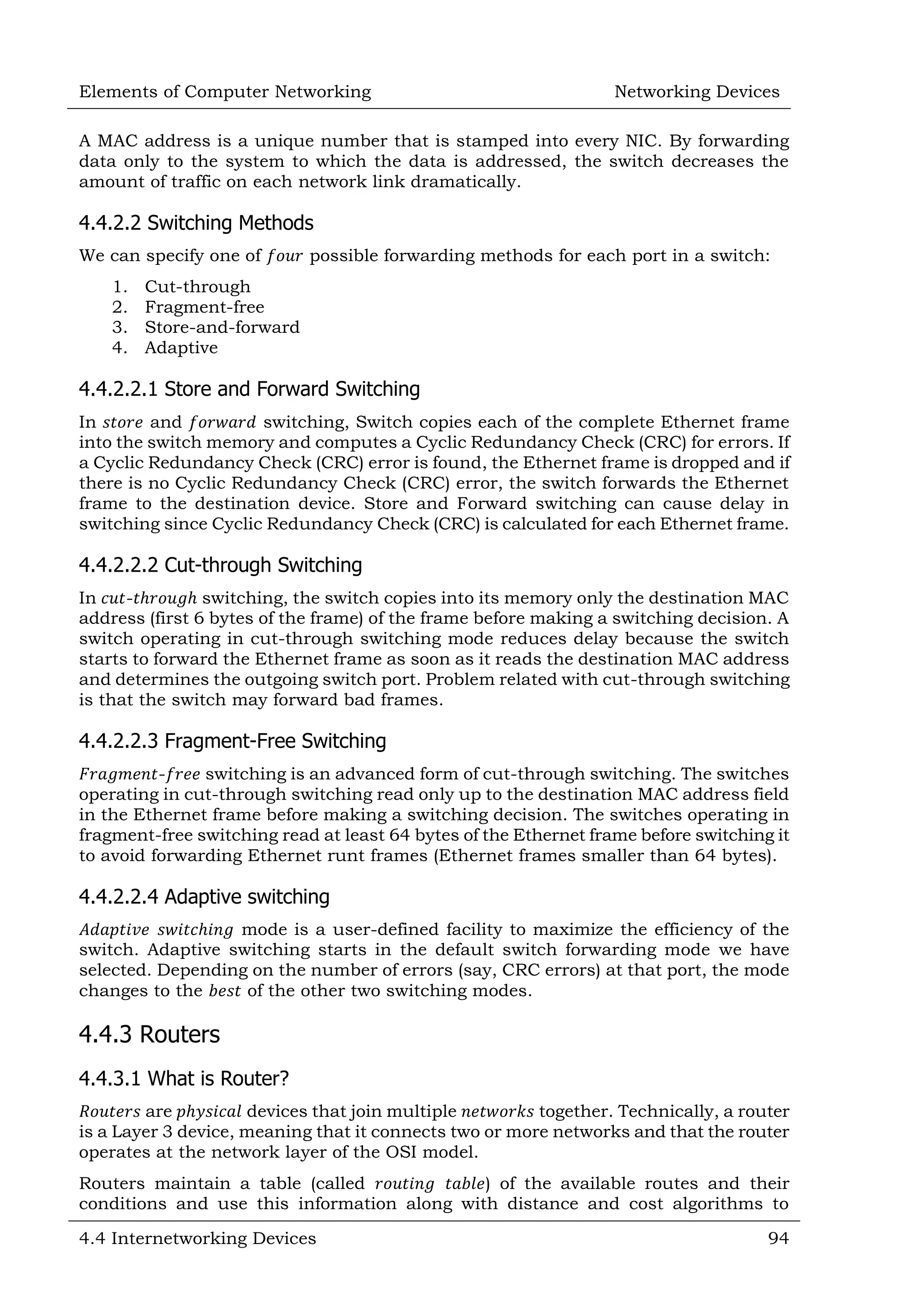
![Elements of Computer Networking Networking Devices 4.4 Internetworking Devices 95 determine the best route for a given packet. Typically, a packet may travel through a number of network points with routers before arriving at its destination. The purpose of the router is to examine incoming packets (layer 3), chose the best path for them through the network, and then switches them to the proper outgoing port. Routers are the most important traffic controlling devices on large networks. Routers are networking devices that forward data packets between networks using headers and 𝑓𝑜𝑟𝑤𝑎𝑟𝑑𝑖𝑛𝑔 𝑡𝑎𝑏𝑙𝑒𝑠 to determine the best path to forward the packets. Routers also provide interconnectivity between 𝑙𝑖𝑘𝑒 and 𝑢𝑛𝑙𝑖𝑘𝑒 media (networks which use different protocols). 4.4.3.2 Understanding Concepts of Routers As an example, assume that we want to send a postcard just based on person names (with minimum information). For example, 𝐵𝑖𝑙𝑙 𝐺𝑎𝑡𝑒s [USA], 𝑆𝑎𝑐ℎ𝑖𝑛 𝑇𝑒𝑛𝑑𝑢𝑙𝑘𝑎𝑟 [India] or 𝐴𝑙𝑏𝑒𝑟𝑡 𝐸𝑖𝑛𝑠𝑡𝑒𝑖𝑛 [USA] it would be routed to them due to their fame; no listing of the street address or the city name would be necessary. The postal system can do such routing to famous personalities, depending on the name alone. In an Internet, a similar discussion is possible: 𝑟𝑒𝑎𝑐ℎ any 𝑤𝑒𝑏𝑠𝑖𝑡𝑒 anywhere in the world without knowing where the site is currently located. Not only that, it is possible to do so very efficiently, within a matter of a few seconds. 4.4.3.2.1 What is Network Routing? How is this possible in a communication network, and how can it be done so quickly? The answer to this question is 𝑁𝑒𝑡𝑤𝑜𝑟𝑘 𝑟𝑜𝑢𝑡𝑖𝑛𝑔. 𝑁𝑒𝑡𝑤𝑜𝑟𝑘 𝑟𝑜𝑢𝑡𝑖𝑛𝑔 is the ability to send a unit of information from source to destination by finding a path through the network, and by doing efficiently and quickly. 4.4.3.2.2 What is Addressing? First, we start with a key and necessary factor, called 𝑎𝑑𝑑𝑟𝑒𝑠𝑠𝑖𝑛𝑔. In many ways, addressing in a network has similarities to postal addressing in the postal system. So, we will start with a brief discussion of the postal addressing system to relate them. A typical postal address that we write on a postcard has several components—the name of the person, followed by the street address with the house number (ℎ𝑜𝑢𝑠𝑒 𝑎𝑑𝑑𝑟𝑒𝑠𝑠), followed by the city, the state name, and the postal code. If we take the](https://image.slidesharecdn.com/sampleelementsofcomputernetworking-150720175354-lva1-app6891/75/Sample-elements-of-computer-networking-19-2048.jpg)