International Journal of Advanced Research in Engineering and Technology (IJARET), ISSN 0976 – 6480(Print), ISSN 0976 – 6499(Online), Volume 6, Issue 1, January (2015), pp. 19-26 © IAEME 19 PLC BASED PID IMPLEMENTATION IN PROCESS CONTROL OF TEMPERATURE FLOW AND LEVEL Ramavatar Singh Rathore1 , Dr. Anil Kumar Sharma2 , Hirendra Kr. Dubey3 1 M.Tech Scholar, Department of Electronic Instrumentation & Control Engineering Institute of Engineering & Technology, Alwar-301030 (Raj.), India 2 Professor & Principal, Department of Electronics & Communication Engineering Institute of Engineering & Technology, Alwar-301030 (Raj.), India 3 Alumni, Department of Electronics & Communication Engineering, Institute of Engineering & Technology, Alwar-301030 (Raj.), India ABSTRACT In the present Industrial scenario the Temperature, Flow, Level, Pressure and density of a process is controlled using the Proportional-Integral-Derivative (PID) controller which is based on microcontroller. Out of the above mentioned variables controlling, Temperature control is very difficult by using ordinary control techniques; hence the motive of our research is to implement PID controller design along with programmable logic controller (PLC) in order to control the time to heat up a particular solution to a desired temperature efficiently without sacrificing the stability of the system. In this work the controlling is based on PLC MISTUBISHI NEXGENIE 1000 NG14RL along with some Analog cards. In this work the controlling of PID controller is performed by using ladder diagram in PLC software Codesys ENE server V2.3. The temperature control, flow and level unit NE40UX are used where the temperature control unit is a special I/O unit that receives inputs directly from RTDs and special I/O unit that receives inputs directly from flow sensors and level sensor of plant. Whatever the temperature, flow, level is desired by the user in accordance with that the set point (SP) is set by the user using the PC. In this work in addition to PLC controlling, Cascade, Ratio and Feedback loops are also used for controlling the above mentioned process parameters. For output control unit NE02AX is used for controlling the Input converters and control valves etc. Keyword: Flow Control, Level Control, PID, PLC, RTD. INTERNATIONAL JOURNAL OF ADVANCED RESEARCH IN ENGINEERING AND TECHNOLOGY (IJARET) ISSN 0976 - 6480 (Print) ISSN 0976 - 6499 (Online) Volume 6, Issue 1, January (2015), pp. 19-26 © IAEME: www.iaeme.com/ IJARET.asp Journal Impact Factor (2014): 7.8273 (Calculated by GISI) www.jifactor.com IJARET © I A E M E
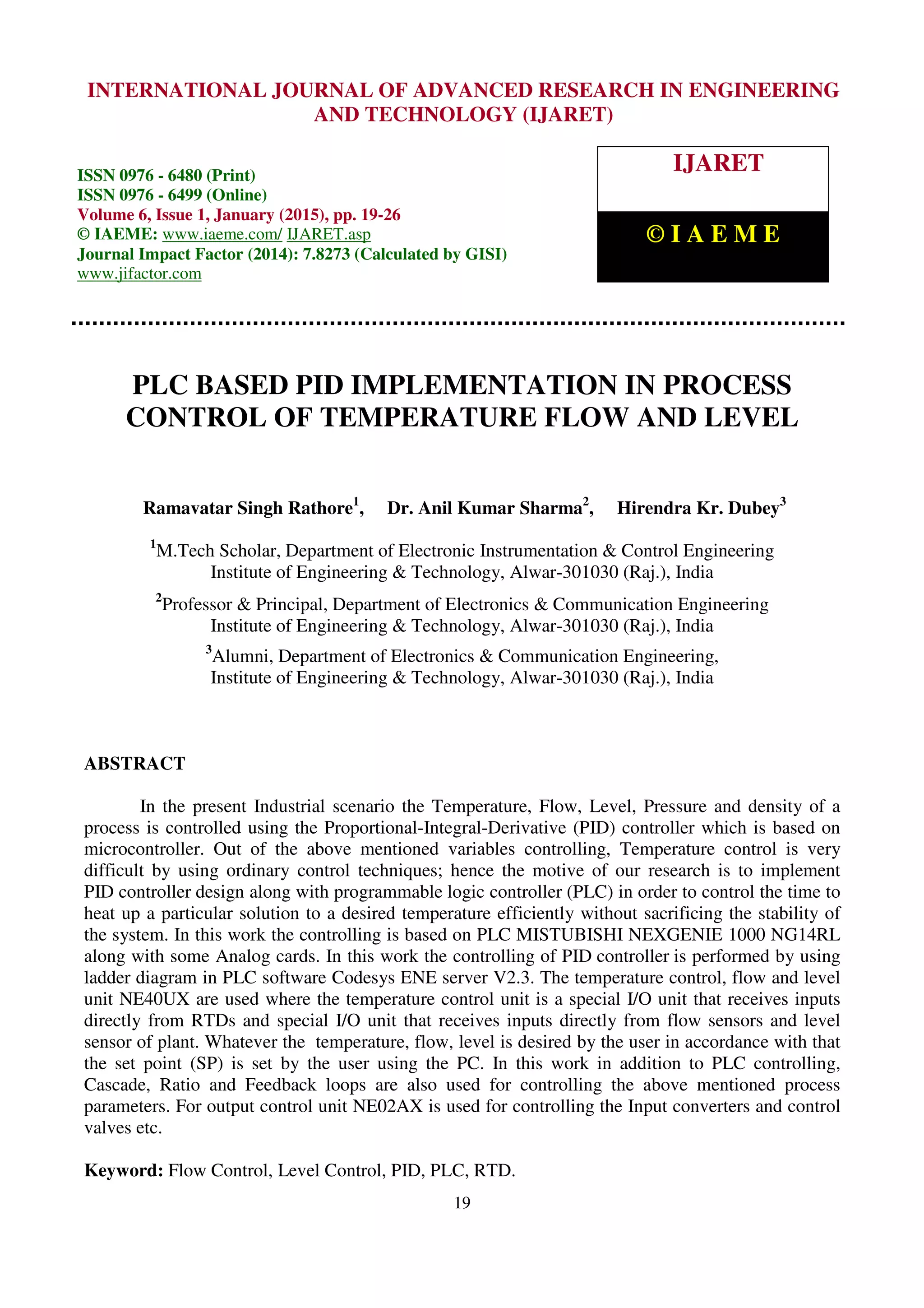
International Journal of Advanced Research in Engineering and Technology (IJARET), ISSN 0976 – 6480(Print), ISSN 0976 – 6499(Online), Volume 6, Issue 1, January (2015), pp. 19-26 © IAEME 20 1. INTRODUCTION To fulfil high control performance requirements and advanced control the control engineering methods used in industries was the proportional, integral and derivative (PID) controller that is widely used since the last four decades. To simplify the controlling in manufacturing system, process control system etc., Programmable logic controller (PLC) is widely used as industrial control. From the several languages described for the PLC programming, the ladder logic is mostly used language. In past the industries which are using automation in controlling the process Temperature, Flow, Level, Pressure and density they use a PID controller which was based on microcontroller. After that for better automation in controlling process of industries PLC was used. Initially the Mitsubishi PLC was originated for on/off (discrete) process control functions, but now a day’s PLC can also operate analog PID control functions as its speed and capability has increased. For example Nexgenie 1000 PLC of Mitsubishi can control various parameters. Codesys software is used for controlling purpose. A computer control system consisting of PLC is designed to improve the level of automation. By using the PC, desired temperature or set point (SP) is set by the user and the process temperature based on the SP temperature is maintained by the controller within the PLC. Regarding from that, the research will be divided in two parts hardware development and software development. RTD is used as the sensor and also to measure the temperature parameter will send the digital signal to the PLC in “ON” or “OFF” signal .The main part of this research work is PLC which can be considered as the ‘brain’ which completely controlled the Temperature, flow and level with the help of feedback loop, cascade loop or ratio control system. Fig.1: PLC Design for PID Controlling. Very complex process control such as used in the chemical industry may require algorithms and performance beyond the capability of even high-performance PLC. Very high-speed or precision controls may also require customized solutions. Then in this work we want to overcome the error which occurs in other controller or in normal digital PLC. The developed controller is implemented on a heater-furnace system and the algorithms are developed using the ladder functions of the PLC. The benefit of this system is that it does not require any external display device which may be HMI, any voltmeter or ammeters or any other devices, because in this all parameters are set or seen in ladder logic program on PC. 2. PROGRAMMABLE LOGIC CONTROLLER A PLC is a digital computer can be used for automation of electromechanical processes such as control of machinery on amusement rides. PLC is a microprocessor based system which takes analog or digital inputs from fields does logical calculations as per the user’s logic program and
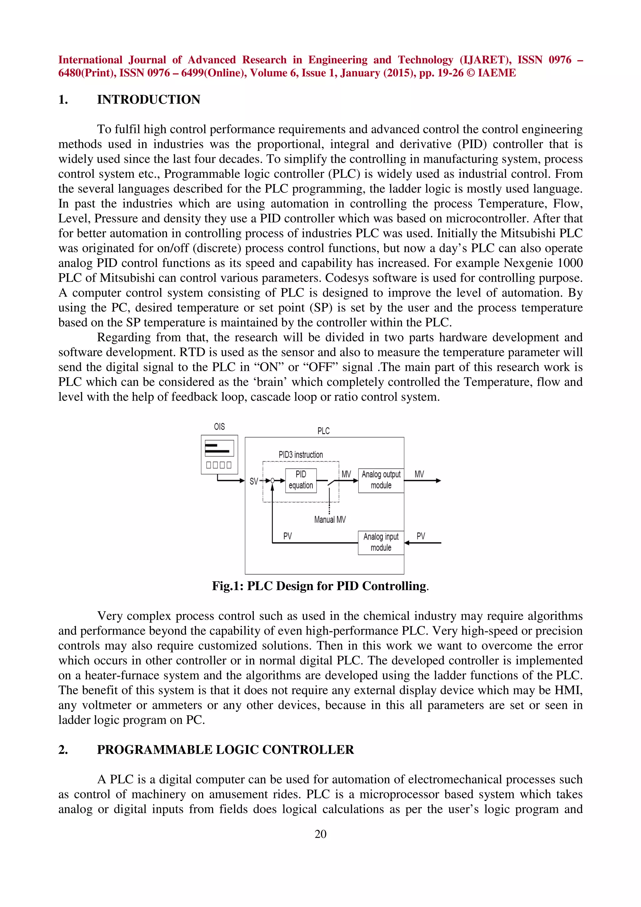
International Journal of Advanced Research in Engineering and Technology (IJARET), ISSN 0976 – 6480(Print), ISSN 0976 – 6499(Online), Volume 6, Issue 1, January (2015), pp. 19-26 © IAEME 21 accordingly gives analog or digital outputs which could be used for monitoring purpose or process controlling. PLCs can be used in many machines and industries. Since 1970’s, PLC system plays a vital role to make human activities easy. It is a type of control system which is when applied changes the behaviour of a system. When industrial revolution can be started, PLC from the feedback becomes choice for manufacturing controls. There are different types of PLCs which are used in industries according to the needs such as ALLEN BRADELY, MISTUBISHI, OMRON and SIEMENS. The main method of PLC is ladder logic. PLC can be programmed, operated and controlled by drawing the lines and devices of ladder diagram with a keyboard onto a display screen. This drawing the converted into computer machine language and run as a user program. It is basically use to control a process that involved relays. This technique is based on relay logic wiring schematics. CoDeSys is a complete development environment for the PLC. (CoDeSys stands for Controlled Development System). 3. PID CONTROL MODEL There are three basic types of controllers: on-off, proportional and PID. This type of controller can be provides proportional with integral and derivative control. These adjustments can be integral and derivative expressed in time-based units; they can also be referred to by their reciprocals. The proportional, integral and derivative terms can be individually adjusted or “tuned” to a particular system using trial and error. In this the measure value is compares by PID controller with a reference set point value. For manipulatable input the error is calculated a new value for a desired value by feedback process. The PID controller can set process outputs depending upon the feedback and changing rate of error signal by which the output is accurate and stable. It (PID) has mainly application in industrial purpose, but now a day it designed for control theory and technology. Because these has a advanced process. An example of the PID speed control system. The error signal e can be represents the difference between the speed command and speed feedback. The proportional control can be multiplies the speed error e by a constant Kp the integral control can be multiplies the e by a constant Ki to correct steady state error and the derivative control can be reduces the overshoot and the rise time or, U(t) = Kp e(t)+ KpKi ∫o e(t)dt + KpKd de(t)/dt (1) Where: U(t): control signal, Kp: Proportional gain, Ki: Integral gain, Kd: Derivative gain. e(t) will be an error term ∫o e(t)dt will be a summation of all past error over time and de(t)/dt will be rate of change of error term. E (t ) = r(t) – y(t) (2) Where; r (t): Set point (SP), y (t): Measured value Fig.2: Typical configuration for a PID control system
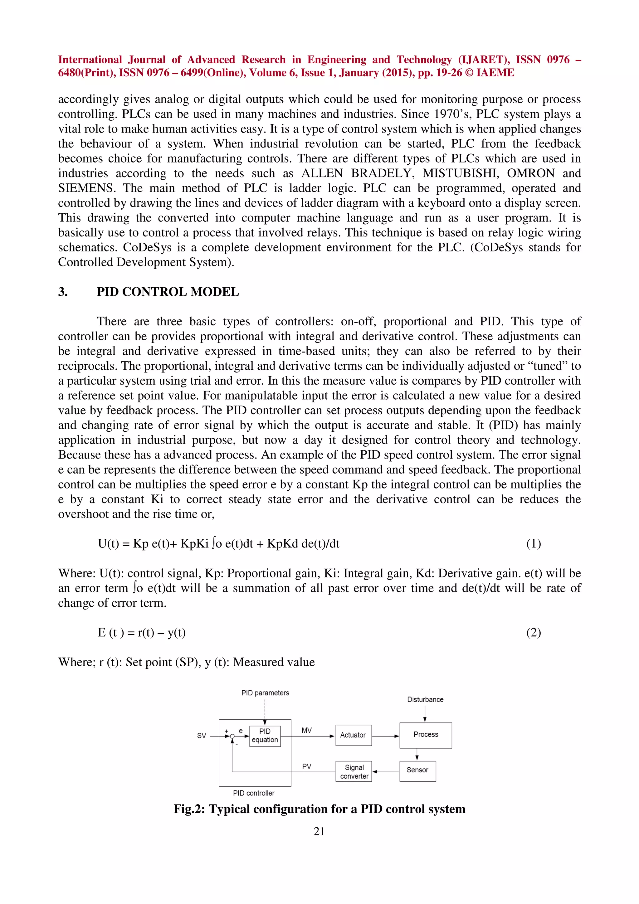
International Journal of Advanced Research in Engineering and Technology (IJARET), ISSN 0976 – 6480(Print), ISSN 0976 – 6499(Online), Volume 6, Issue 1, January (2015), pp. 19-26 © IAEME 22 Temperature Control System: If the Measured variable is less than the set point, (MV < SP), it means, that the temperature of the cold liquid OUTLET is below then that desired. It means that the amount of heat transfer from the hot water to the cold liquid is less than that desired. There may be two reasons for that i.e. the temperature of the Hot water may be less, or the flow of hot water may be less and the flow of cold water may be more. The complete model is shown in Fig.3. Fig. 3 The Proposed Model of Controller Level Control System: A Level Capacitance Probe (LIC) senses the level of the tank. A probe connecting to this transmits the signal. The effective level of the tank is 300mm. For this head, the output signal range of the Level Capacitance Probe is 4-20mA. Corresponding to the level in the tank, an electrical signal is transmitted to the Level Indicator Controller (LIC) (ex: if the level in the tank is 150mm, then a signal of 12mA is transmitted). The controller LIC reads this value (which is known as the measured variable or MV), compares it with the set point (SP) value. The difference of these two values; known as the ERROR, is fed to the controller. The liquid is sucked into the Pump P-1 from Tank T-1 and finally discharged to tank T-2 through Orifice meter (FI) if the level in the tank T-1 is low then PCV will open up further to increase the amount of flow through it, thereby increasing the level. If the level is higher, the controller will send a reverse signal to limit the opening of the PCV-2 and hence to limit the flow. Flow Control System: The working principle of turbine flow transmitter is such that if a fluid moves through a pipe and acts on the vanes of a turbine the turbine will start to spin and rotate. The rate of spin is measured to calculate the flow). The Turbine flow transmitter TFTx senses the flow and sends out the signal to the controller FIC. The output signal from the TFTx to the FIC is in the range of 4- 20mA. The TFTx is calibrated in a manner; such that, the input flow range of 0-20 lpm corresponds to an output signal of 4-20mA. The controller FIC compares this value, which is known as the MEASURED VARIABLE or MV with the set point (SP). The difference in the two values known as the ERROR is sent to the final Control element i.e. Pneumatic Control Valve. In this case, the final control element is PCV. If the flow is higher than that which is desired (i.e. MV > SP), the controller FIC will send a signal such that the output of the PCV decreases, so that the flow through it reduces. In the reverse case, if the flow is less than the desired (i.e. MV < SP) the output of the controller is increased such that the flow through PCV is increased.
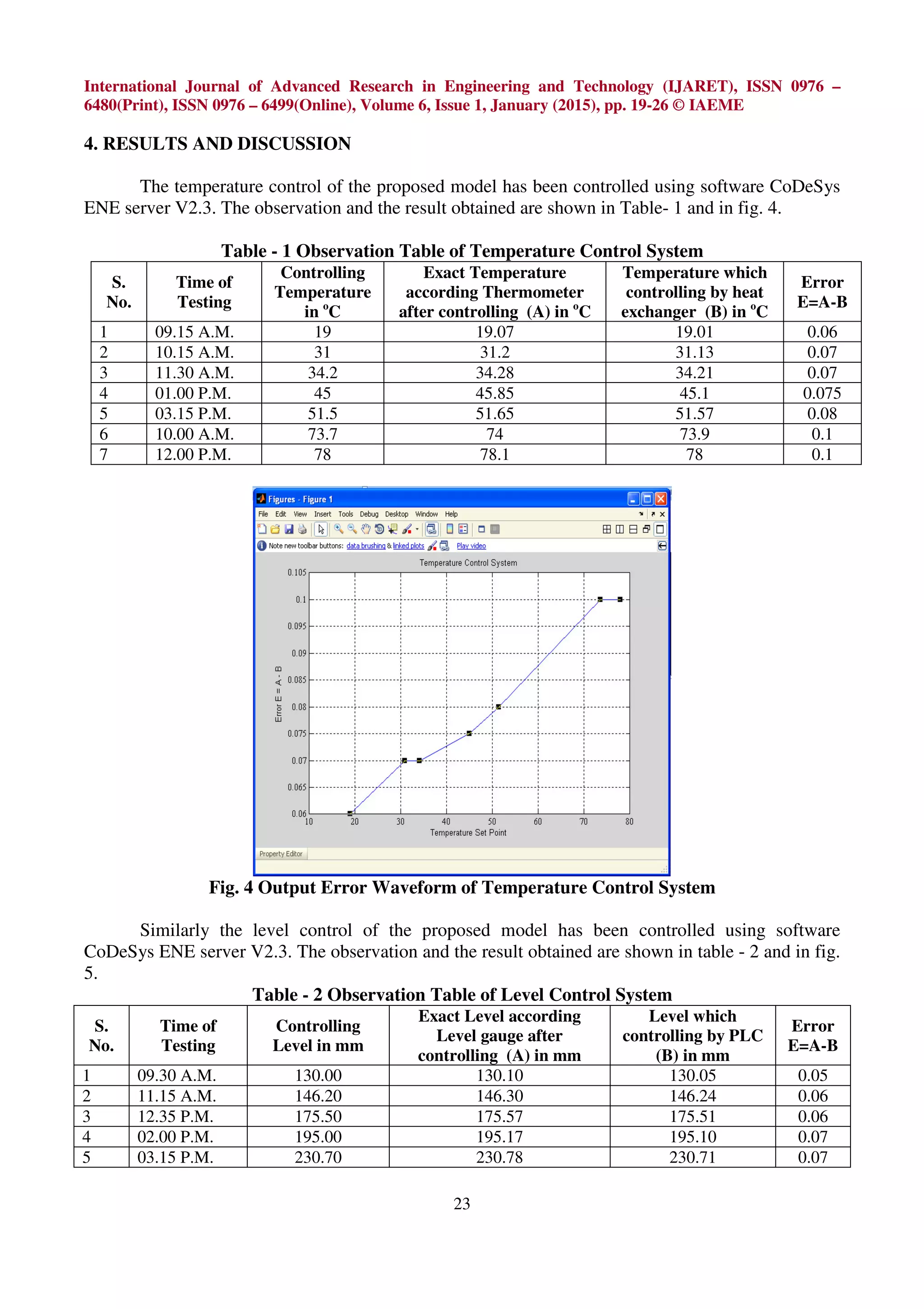
International Journal of Advanced Research in Engineering and Technology (IJARET), ISSN 0976 – 6480(Print), ISSN 0976 – 6499(Online), Volume 6, Issue 1, January (2015), pp. 19-26 © IAEME 23 4. RESULTS AND DISCUSSION The temperature control of the proposed model has been controlled using software CoDeSys ENE server V2.3. The observation and the result obtained are shown in Table- 1 and in fig. 4. Table - 1 Observation Table of Temperature Control System S. No. Time of Testing Controlling Temperature in o C Exact Temperature according Thermometer after controlling (A) in o C Temperature which controlling by heat exchanger (B) in o C Error E=A-B 1 09.15 A.M. 19 19.07 19.01 0.06 2 10.15 A.M. 31 31.2 31.13 0.07 3 11.30 A.M. 34.2 34.28 34.21 0.07 4 01.00 P.M. 45 45.85 45.1 0.075 5 03.15 P.M. 51.5 51.65 51.57 0.08 6 10.00 A.M. 73.7 74 73.9 0.1 7 12.00 P.M. 78 78.1 78 0.1 Fig. 4 Output Error Waveform of Temperature Control System Similarly the level control of the proposed model has been controlled using software CoDeSys ENE server V2.3. The observation and the result obtained are shown in table - 2 and in fig. 5. Table - 2 Observation Table of Level Control System S. No. Time of Testing Controlling Level in mm Exact Level according Level gauge after controlling (A) in mm Level which controlling by PLC (B) in mm Error E=A-B 1 09.30 A.M. 130.00 130.10 130.05 0.05 2 11.15 A.M. 146.20 146.30 146.24 0.06 3 12.35 P.M. 175.50 175.57 175.51 0.06 4 02.00 P.M. 195.00 195.17 195.10 0.07 5 03.15 P.M. 230.70 230.78 230.71 0.07
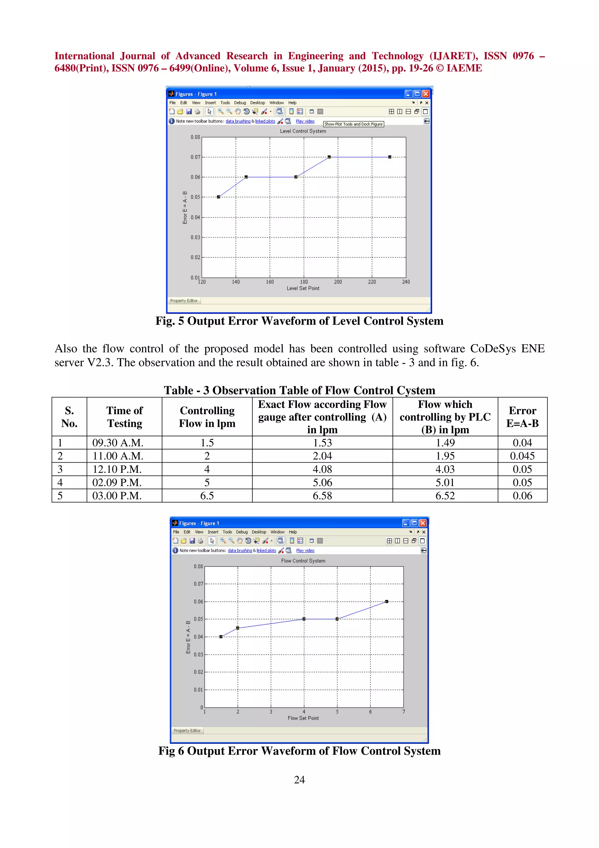
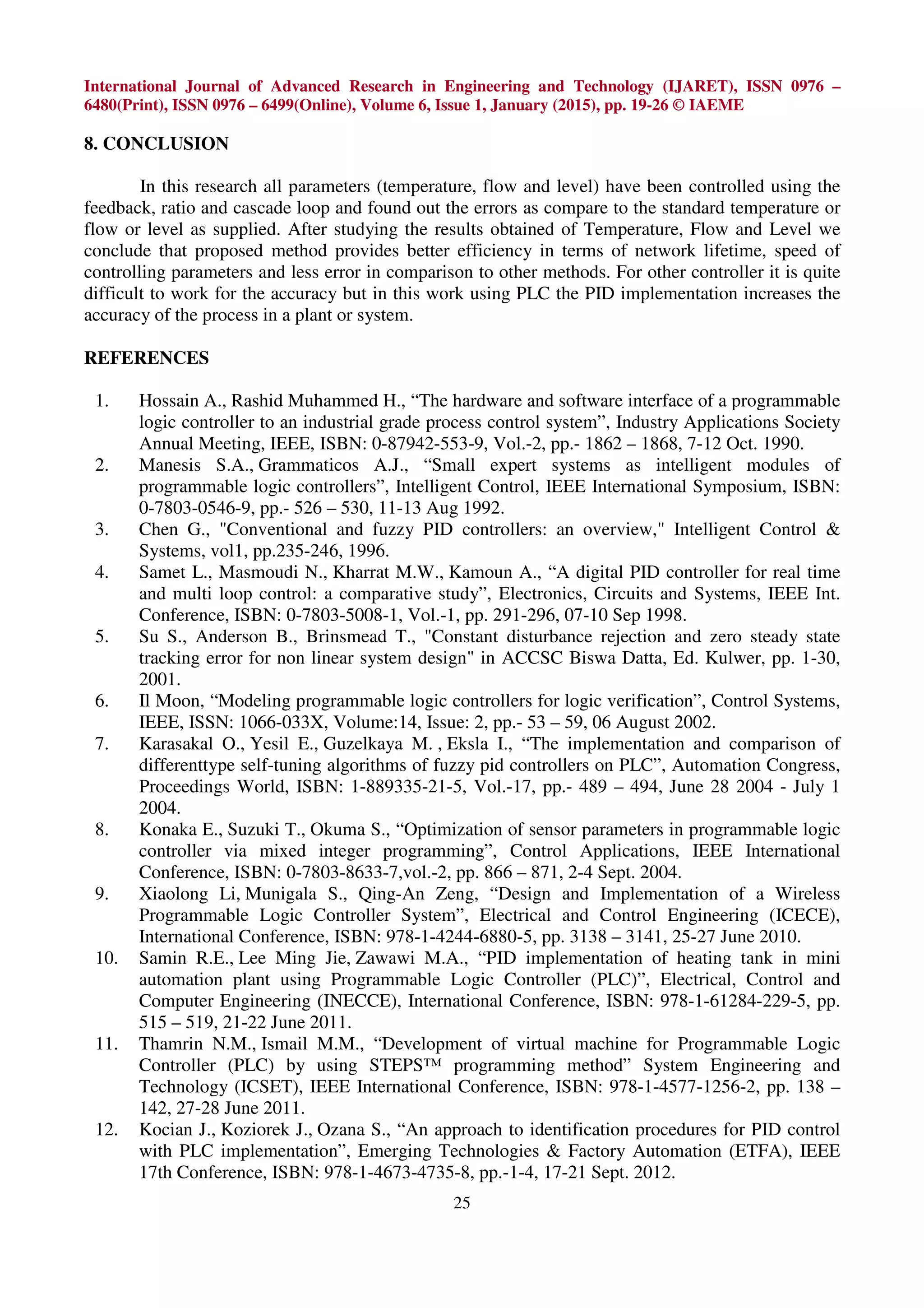
International Journal of Advanced Research in Engineering and Technology (IJARET), ISSN 0976 – 6480(Print), ISSN 0976 – 6499(Online), Volume 6, Issue 1, January (2015), pp. 19-26 © IAEME 24 Fig. 5 Output Error Waveform of Level Control System Also the flow control of the proposed model has been controlled using software CoDeSys ENE server V2.3. The observation and the result obtained are shown in table - 3 and in fig. 6. Table - 3 Observation Table of Flow Control Cystem S. No. Time of Testing Controlling Flow in lpm Exact Flow according Flow gauge after controlling (A) in lpm Flow which controlling by PLC (B) in lpm Error E=A-B 1 09.30 A.M. 1.5 1.53 1.49 0.04 2 11.00 A.M. 2 2.04 1.95 0.045 3 12.10 P.M. 4 4.08 4.03 0.05 4 02.09 P.M. 5 5.06 5.01 0.05 5 03.00 P.M. 6.5 6.58 6.52 0.06 Fig 6 Output Error Waveform of Flow Control System
International Journal of Advanced Research in Engineering and Technology (IJARET), ISSN 0976 – 6480(Print), ISSN 0976 – 6499(Online), Volume 6, Issue 1, January (2015), pp. 19-26 © IAEME 25 8. CONCLUSION In this research all parameters (temperature, flow and level) have been controlled using the feedback, ratio and cascade loop and found out the errors as compare to the standard temperature or flow or level as supplied. After studying the results obtained of Temperature, Flow and Level we conclude that proposed method provides better efficiency in terms of network lifetime, speed of controlling parameters and less error in comparison to other methods. For other controller it is quite difficult to work for the accuracy but in this work using PLC the PID implementation increases the accuracy of the process in a plant or system. REFERENCES 1. Hossain A., Rashid Muhammed H., “The hardware and software interface of a programmable logic controller to an industrial grade process control system”, Industry Applications Society Annual Meeting, IEEE, ISBN: 0-87942-553-9, Vol.-2, pp.- 1862 – 1868, 7-12 Oct. 1990. 2. Manesis S.A., Grammaticos A.J., “Small expert systems as intelligent modules of programmable logic controllers”, Intelligent Control, IEEE International Symposium, ISBN: 0-7803-0546-9, pp.- 526 – 530, 11-13 Aug 1992. 3. Chen G., "Conventional and fuzzy PID controllers: an overview," Intelligent Control & Systems, vol1, pp.235-246, 1996. 4. Samet L., Masmoudi N., Kharrat M.W., Kamoun A., “A digital PID controller for real time and multi loop control: a comparative study”, Electronics, Circuits and Systems, IEEE Int. Conference, ISBN: 0-7803-5008-1, Vol.-1, pp. 291-296, 07-10 Sep 1998. 5. Su S., Anderson B., Brinsmead T., "Constant disturbance rejection and zero steady state tracking error for non linear system design" in ACCSC Biswa Datta, Ed. Kulwer, pp. 1-30, 2001. 6. Il Moon, “Modeling programmable logic controllers for logic verification”, Control Systems, IEEE, ISSN: 1066-033X, Volume:14, Issue: 2, pp.- 53 – 59, 06 August 2002. 7. Karasakal O., Yesil E., Guzelkaya M. , Eksla I., “The implementation and comparison of differenttype self-tuning algorithms of fuzzy pid controllers on PLC”, Automation Congress, Proceedings World, ISBN: 1-889335-21-5, Vol.-17, pp.- 489 – 494, June 28 2004 - July 1 2004. 8. Konaka E., Suzuki T., Okuma S., “Optimization of sensor parameters in programmable logic controller via mixed integer programming”, Control Applications, IEEE International Conference, ISBN: 0-7803-8633-7,vol.-2, pp. 866 – 871, 2-4 Sept. 2004. 9. Xiaolong Li, Munigala S., Qing-An Zeng, “Design and Implementation of a Wireless Programmable Logic Controller System”, Electrical and Control Engineering (ICECE), International Conference, ISBN: 978-1-4244-6880-5, pp. 3138 – 3141, 25-27 June 2010. 10. Samin R.E., Lee Ming Jie, Zawawi M.A., “PID implementation of heating tank in mini automation plant using Programmable Logic Controller (PLC)”, Electrical, Control and Computer Engineering (INECCE), International Conference, ISBN: 978-1-61284-229-5, pp. 515 – 519, 21-22 June 2011. 11. Thamrin N.M., Ismail M.M., “Development of virtual machine for Programmable Logic Controller (PLC) by using STEPS™ programming method” System Engineering and Technology (ICSET), IEEE International Conference, ISBN: 978-1-4577-1256-2, pp. 138 – 142, 27-28 June 2011. 12. Kocian J., Koziorek J., Ozana S., “An approach to identification procedures for PID control with PLC implementation”, Emerging Technologies & Factory Automation (ETFA), IEEE 17th Conference, ISBN: 978-1-4673-4735-8, pp.-1-4, 17-21 Sept. 2012.
International Journal of Advanced Research in Engineering and Technology (IJARET), ISSN 0976 – 6480(Print), ISSN 0976 – 6499(Online), Volume 6, Issue 1, January (2015), pp. 19-26 © IAEME 26 13. Balaji M., Porkumaran K., “A Mamdani-type fuzzy gain adapter for PID controller on a thermal system using PLC”, India Conference (INDICON), ISBN: 978-1-4673-2270-6, pp.- 670-675, 7-9 Dec. 2012. 14. Kumar N., Majumdar S., Babu G.M. “Automatic control of tidal power plant”, Emerging Trends in Electrical Engineering and Energy Management (ICETEEEM), International Conference, ISBN: 978-1-4673-4633-7, pp.- 24-28, 13-15 Dec. 2012. 15. Illes C., Popa G.N., Filip I., “Water level control system using PLC and wireless sensors”, Computational Cybernetics (ICCC), IEEE 9th International Conference, ISBN: 978-1-4799- 0060-2, pp.- 195 – 199, 8-10 July 2013. 16. Engin D., Izmir, Turkey, Engin M. “Auto-tuning of PID parameters with programmable logic controller”, Mechatronics and Automation (ICMA), IEEE International Conference, ISBN: 978-1-4673-5557-5, pp.- 1469 – 1474, 4-7 Aug. 2013. 17. Phani Chavali, Peng Yang, Arye Nehorai, “ A Distributed Algorithm of appliance scheduling for Home Energy Management System”, IEEE Transaction on Smart Grid, Vol.-5, No.-1, pp. 282-290, January 2014. 18. Vinothini E., Suganya N., “Automated Water distribution and Performance Monitoring System” International Journal of Engineering and Innovative Technology (IJEIT) Vol-3, no.- 8, pp. 3-32, February 2014. 19. Chaozhi Cai, Yunhua Li, Sujun Dong, “Design and implementation of gas temperature control system of heat-calibration wind tunnel”, Advanced Intelligent Mechatronics (AIM), IEEE/ASME International Conference, pp.- 291-296, 8-11 July 2014. 20. Arvind N. Nakiya, Mahesh A. Makwana and Ramesh R. Gajera, “An External Plunge Grinding Machine with Control Panel Automation Technique Based on Mitsubishi PLC System” International Journal of Electrical Engineering & Technology (IJEET), Volume 4, Issue 4, 2012, pp. 197 - 204, ISSN Print : 0976-6545, ISSN Online: 0976-6553. 21. VenkataRamesh.Edara, B.Amarendra Reddy, Srikanth Monangi, M.Vimala, “Analytical Structures for Fuzzy PID Controllers and Applications” International Journal of Electrical Engineering & Technology (IJEET), Volume 1, Issue 1, 2010, pp. 1 - 17, ISSN Print: 0976- 6545, ISSN Online: 0976-6553. 22. Rajan P. Thomas, Akhil S, Jithin K K, Sanjay S G and George Joseph, “Hybrid Ac-Dc Microgrid with Intelligent Load Flow Control” International Journal of Electrical Engineering & Technology (IJEET), Volume 5, Issue 4, 2014, pp. 104 - 110, ISSN Print: 0976-6545, ISSN Online: 0976-6553.

Plc based pid implementation in process control of temperature flow and level

  • 1.
    International Journal ofAdvanced Research in Engineering and Technology (IJARET), ISSN 0976 – 6480(Print), ISSN 0976 – 6499(Online), Volume 6, Issue 1, January (2015), pp. 19-26 © IAEME 19 PLC BASED PID IMPLEMENTATION IN PROCESS CONTROL OF TEMPERATURE FLOW AND LEVEL Ramavatar Singh Rathore1 , Dr. Anil Kumar Sharma2 , Hirendra Kr. Dubey3 1 M.Tech Scholar, Department of Electronic Instrumentation & Control Engineering Institute of Engineering & Technology, Alwar-301030 (Raj.), India 2 Professor & Principal, Department of Electronics & Communication Engineering Institute of Engineering & Technology, Alwar-301030 (Raj.), India 3 Alumni, Department of Electronics & Communication Engineering, Institute of Engineering & Technology, Alwar-301030 (Raj.), India ABSTRACT In the present Industrial scenario the Temperature, Flow, Level, Pressure and density of a process is controlled using the Proportional-Integral-Derivative (PID) controller which is based on microcontroller. Out of the above mentioned variables controlling, Temperature control is very difficult by using ordinary control techniques; hence the motive of our research is to implement PID controller design along with programmable logic controller (PLC) in order to control the time to heat up a particular solution to a desired temperature efficiently without sacrificing the stability of the system. In this work the controlling is based on PLC MISTUBISHI NEXGENIE 1000 NG14RL along with some Analog cards. In this work the controlling of PID controller is performed by using ladder diagram in PLC software Codesys ENE server V2.3. The temperature control, flow and level unit NE40UX are used where the temperature control unit is a special I/O unit that receives inputs directly from RTDs and special I/O unit that receives inputs directly from flow sensors and level sensor of plant. Whatever the temperature, flow, level is desired by the user in accordance with that the set point (SP) is set by the user using the PC. In this work in addition to PLC controlling, Cascade, Ratio and Feedback loops are also used for controlling the above mentioned process parameters. For output control unit NE02AX is used for controlling the Input converters and control valves etc. Keyword: Flow Control, Level Control, PID, PLC, RTD. INTERNATIONAL JOURNAL OF ADVANCED RESEARCH IN ENGINEERING AND TECHNOLOGY (IJARET) ISSN 0976 - 6480 (Print) ISSN 0976 - 6499 (Online) Volume 6, Issue 1, January (2015), pp. 19-26 © IAEME: www.iaeme.com/ IJARET.asp Journal Impact Factor (2014): 7.8273 (Calculated by GISI) www.jifactor.com IJARET © I A E M E
  • 2.
    International Journal ofAdvanced Research in Engineering and Technology (IJARET), ISSN 0976 – 6480(Print), ISSN 0976 – 6499(Online), Volume 6, Issue 1, January (2015), pp. 19-26 © IAEME 20 1. INTRODUCTION To fulfil high control performance requirements and advanced control the control engineering methods used in industries was the proportional, integral and derivative (PID) controller that is widely used since the last four decades. To simplify the controlling in manufacturing system, process control system etc., Programmable logic controller (PLC) is widely used as industrial control. From the several languages described for the PLC programming, the ladder logic is mostly used language. In past the industries which are using automation in controlling the process Temperature, Flow, Level, Pressure and density they use a PID controller which was based on microcontroller. After that for better automation in controlling process of industries PLC was used. Initially the Mitsubishi PLC was originated for on/off (discrete) process control functions, but now a day’s PLC can also operate analog PID control functions as its speed and capability has increased. For example Nexgenie 1000 PLC of Mitsubishi can control various parameters. Codesys software is used for controlling purpose. A computer control system consisting of PLC is designed to improve the level of automation. By using the PC, desired temperature or set point (SP) is set by the user and the process temperature based on the SP temperature is maintained by the controller within the PLC. Regarding from that, the research will be divided in two parts hardware development and software development. RTD is used as the sensor and also to measure the temperature parameter will send the digital signal to the PLC in “ON” or “OFF” signal .The main part of this research work is PLC which can be considered as the ‘brain’ which completely controlled the Temperature, flow and level with the help of feedback loop, cascade loop or ratio control system. Fig.1: PLC Design for PID Controlling. Very complex process control such as used in the chemical industry may require algorithms and performance beyond the capability of even high-performance PLC. Very high-speed or precision controls may also require customized solutions. Then in this work we want to overcome the error which occurs in other controller or in normal digital PLC. The developed controller is implemented on a heater-furnace system and the algorithms are developed using the ladder functions of the PLC. The benefit of this system is that it does not require any external display device which may be HMI, any voltmeter or ammeters or any other devices, because in this all parameters are set or seen in ladder logic program on PC. 2. PROGRAMMABLE LOGIC CONTROLLER A PLC is a digital computer can be used for automation of electromechanical processes such as control of machinery on amusement rides. PLC is a microprocessor based system which takes analog or digital inputs from fields does logical calculations as per the user’s logic program and
  • 3.
    International Journal ofAdvanced Research in Engineering and Technology (IJARET), ISSN 0976 – 6480(Print), ISSN 0976 – 6499(Online), Volume 6, Issue 1, January (2015), pp. 19-26 © IAEME 21 accordingly gives analog or digital outputs which could be used for monitoring purpose or process controlling. PLCs can be used in many machines and industries. Since 1970’s, PLC system plays a vital role to make human activities easy. It is a type of control system which is when applied changes the behaviour of a system. When industrial revolution can be started, PLC from the feedback becomes choice for manufacturing controls. There are different types of PLCs which are used in industries according to the needs such as ALLEN BRADELY, MISTUBISHI, OMRON and SIEMENS. The main method of PLC is ladder logic. PLC can be programmed, operated and controlled by drawing the lines and devices of ladder diagram with a keyboard onto a display screen. This drawing the converted into computer machine language and run as a user program. It is basically use to control a process that involved relays. This technique is based on relay logic wiring schematics. CoDeSys is a complete development environment for the PLC. (CoDeSys stands for Controlled Development System). 3. PID CONTROL MODEL There are three basic types of controllers: on-off, proportional and PID. This type of controller can be provides proportional with integral and derivative control. These adjustments can be integral and derivative expressed in time-based units; they can also be referred to by their reciprocals. The proportional, integral and derivative terms can be individually adjusted or “tuned” to a particular system using trial and error. In this the measure value is compares by PID controller with a reference set point value. For manipulatable input the error is calculated a new value for a desired value by feedback process. The PID controller can set process outputs depending upon the feedback and changing rate of error signal by which the output is accurate and stable. It (PID) has mainly application in industrial purpose, but now a day it designed for control theory and technology. Because these has a advanced process. An example of the PID speed control system. The error signal e can be represents the difference between the speed command and speed feedback. The proportional control can be multiplies the speed error e by a constant Kp the integral control can be multiplies the e by a constant Ki to correct steady state error and the derivative control can be reduces the overshoot and the rise time or, U(t) = Kp e(t)+ KpKi ∫o e(t)dt + KpKd de(t)/dt (1) Where: U(t): control signal, Kp: Proportional gain, Ki: Integral gain, Kd: Derivative gain. e(t) will be an error term ∫o e(t)dt will be a summation of all past error over time and de(t)/dt will be rate of change of error term. E (t ) = r(t) – y(t) (2) Where; r (t): Set point (SP), y (t): Measured value Fig.2: Typical configuration for a PID control system
  • 4.
    International Journal ofAdvanced Research in Engineering and Technology (IJARET), ISSN 0976 – 6480(Print), ISSN 0976 – 6499(Online), Volume 6, Issue 1, January (2015), pp. 19-26 © IAEME 22 Temperature Control System: If the Measured variable is less than the set point, (MV < SP), it means, that the temperature of the cold liquid OUTLET is below then that desired. It means that the amount of heat transfer from the hot water to the cold liquid is less than that desired. There may be two reasons for that i.e. the temperature of the Hot water may be less, or the flow of hot water may be less and the flow of cold water may be more. The complete model is shown in Fig.3. Fig. 3 The Proposed Model of Controller Level Control System: A Level Capacitance Probe (LIC) senses the level of the tank. A probe connecting to this transmits the signal. The effective level of the tank is 300mm. For this head, the output signal range of the Level Capacitance Probe is 4-20mA. Corresponding to the level in the tank, an electrical signal is transmitted to the Level Indicator Controller (LIC) (ex: if the level in the tank is 150mm, then a signal of 12mA is transmitted). The controller LIC reads this value (which is known as the measured variable or MV), compares it with the set point (SP) value. The difference of these two values; known as the ERROR, is fed to the controller. The liquid is sucked into the Pump P-1 from Tank T-1 and finally discharged to tank T-2 through Orifice meter (FI) if the level in the tank T-1 is low then PCV will open up further to increase the amount of flow through it, thereby increasing the level. If the level is higher, the controller will send a reverse signal to limit the opening of the PCV-2 and hence to limit the flow. Flow Control System: The working principle of turbine flow transmitter is such that if a fluid moves through a pipe and acts on the vanes of a turbine the turbine will start to spin and rotate. The rate of spin is measured to calculate the flow). The Turbine flow transmitter TFTx senses the flow and sends out the signal to the controller FIC. The output signal from the TFTx to the FIC is in the range of 4- 20mA. The TFTx is calibrated in a manner; such that, the input flow range of 0-20 lpm corresponds to an output signal of 4-20mA. The controller FIC compares this value, which is known as the MEASURED VARIABLE or MV with the set point (SP). The difference in the two values known as the ERROR is sent to the final Control element i.e. Pneumatic Control Valve. In this case, the final control element is PCV. If the flow is higher than that which is desired (i.e. MV > SP), the controller FIC will send a signal such that the output of the PCV decreases, so that the flow through it reduces. In the reverse case, if the flow is less than the desired (i.e. MV < SP) the output of the controller is increased such that the flow through PCV is increased.
  • 5.
    International Journal ofAdvanced Research in Engineering and Technology (IJARET), ISSN 0976 – 6480(Print), ISSN 0976 – 6499(Online), Volume 6, Issue 1, January (2015), pp. 19-26 © IAEME 23 4. RESULTS AND DISCUSSION The temperature control of the proposed model has been controlled using software CoDeSys ENE server V2.3. The observation and the result obtained are shown in Table- 1 and in fig. 4. Table - 1 Observation Table of Temperature Control System S. No. Time of Testing Controlling Temperature in o C Exact Temperature according Thermometer after controlling (A) in o C Temperature which controlling by heat exchanger (B) in o C Error E=A-B 1 09.15 A.M. 19 19.07 19.01 0.06 2 10.15 A.M. 31 31.2 31.13 0.07 3 11.30 A.M. 34.2 34.28 34.21 0.07 4 01.00 P.M. 45 45.85 45.1 0.075 5 03.15 P.M. 51.5 51.65 51.57 0.08 6 10.00 A.M. 73.7 74 73.9 0.1 7 12.00 P.M. 78 78.1 78 0.1 Fig. 4 Output Error Waveform of Temperature Control System Similarly the level control of the proposed model has been controlled using software CoDeSys ENE server V2.3. The observation and the result obtained are shown in table - 2 and in fig. 5. Table - 2 Observation Table of Level Control System S. No. Time of Testing Controlling Level in mm Exact Level according Level gauge after controlling (A) in mm Level which controlling by PLC (B) in mm Error E=A-B 1 09.30 A.M. 130.00 130.10 130.05 0.05 2 11.15 A.M. 146.20 146.30 146.24 0.06 3 12.35 P.M. 175.50 175.57 175.51 0.06 4 02.00 P.M. 195.00 195.17 195.10 0.07 5 03.15 P.M. 230.70 230.78 230.71 0.07
  • 6.
    International Journal ofAdvanced Research in Engineering and Technology (IJARET), ISSN 0976 – 6480(Print), ISSN 0976 – 6499(Online), Volume 6, Issue 1, January (2015), pp. 19-26 © IAEME 24 Fig. 5 Output Error Waveform of Level Control System Also the flow control of the proposed model has been controlled using software CoDeSys ENE server V2.3. The observation and the result obtained are shown in table - 3 and in fig. 6. Table - 3 Observation Table of Flow Control Cystem S. No. Time of Testing Controlling Flow in lpm Exact Flow according Flow gauge after controlling (A) in lpm Flow which controlling by PLC (B) in lpm Error E=A-B 1 09.30 A.M. 1.5 1.53 1.49 0.04 2 11.00 A.M. 2 2.04 1.95 0.045 3 12.10 P.M. 4 4.08 4.03 0.05 4 02.09 P.M. 5 5.06 5.01 0.05 5 03.00 P.M. 6.5 6.58 6.52 0.06 Fig 6 Output Error Waveform of Flow Control System
  • 7.
    International Journal ofAdvanced Research in Engineering and Technology (IJARET), ISSN 0976 – 6480(Print), ISSN 0976 – 6499(Online), Volume 6, Issue 1, January (2015), pp. 19-26 © IAEME 25 8. CONCLUSION In this research all parameters (temperature, flow and level) have been controlled using the feedback, ratio and cascade loop and found out the errors as compare to the standard temperature or flow or level as supplied. After studying the results obtained of Temperature, Flow and Level we conclude that proposed method provides better efficiency in terms of network lifetime, speed of controlling parameters and less error in comparison to other methods. For other controller it is quite difficult to work for the accuracy but in this work using PLC the PID implementation increases the accuracy of the process in a plant or system. REFERENCES 1. Hossain A., Rashid Muhammed H., “The hardware and software interface of a programmable logic controller to an industrial grade process control system”, Industry Applications Society Annual Meeting, IEEE, ISBN: 0-87942-553-9, Vol.-2, pp.- 1862 – 1868, 7-12 Oct. 1990. 2. Manesis S.A., Grammaticos A.J., “Small expert systems as intelligent modules of programmable logic controllers”, Intelligent Control, IEEE International Symposium, ISBN: 0-7803-0546-9, pp.- 526 – 530, 11-13 Aug 1992. 3. Chen G., "Conventional and fuzzy PID controllers: an overview," Intelligent Control & Systems, vol1, pp.235-246, 1996. 4. Samet L., Masmoudi N., Kharrat M.W., Kamoun A., “A digital PID controller for real time and multi loop control: a comparative study”, Electronics, Circuits and Systems, IEEE Int. Conference, ISBN: 0-7803-5008-1, Vol.-1, pp. 291-296, 07-10 Sep 1998. 5. Su S., Anderson B., Brinsmead T., "Constant disturbance rejection and zero steady state tracking error for non linear system design" in ACCSC Biswa Datta, Ed. Kulwer, pp. 1-30, 2001. 6. Il Moon, “Modeling programmable logic controllers for logic verification”, Control Systems, IEEE, ISSN: 1066-033X, Volume:14, Issue: 2, pp.- 53 – 59, 06 August 2002. 7. Karasakal O., Yesil E., Guzelkaya M. , Eksla I., “The implementation and comparison of differenttype self-tuning algorithms of fuzzy pid controllers on PLC”, Automation Congress, Proceedings World, ISBN: 1-889335-21-5, Vol.-17, pp.- 489 – 494, June 28 2004 - July 1 2004. 8. Konaka E., Suzuki T., Okuma S., “Optimization of sensor parameters in programmable logic controller via mixed integer programming”, Control Applications, IEEE International Conference, ISBN: 0-7803-8633-7,vol.-2, pp. 866 – 871, 2-4 Sept. 2004. 9. Xiaolong Li, Munigala S., Qing-An Zeng, “Design and Implementation of a Wireless Programmable Logic Controller System”, Electrical and Control Engineering (ICECE), International Conference, ISBN: 978-1-4244-6880-5, pp. 3138 – 3141, 25-27 June 2010. 10. Samin R.E., Lee Ming Jie, Zawawi M.A., “PID implementation of heating tank in mini automation plant using Programmable Logic Controller (PLC)”, Electrical, Control and Computer Engineering (INECCE), International Conference, ISBN: 978-1-61284-229-5, pp. 515 – 519, 21-22 June 2011. 11. Thamrin N.M., Ismail M.M., “Development of virtual machine for Programmable Logic Controller (PLC) by using STEPS™ programming method” System Engineering and Technology (ICSET), IEEE International Conference, ISBN: 978-1-4577-1256-2, pp. 138 – 142, 27-28 June 2011. 12. Kocian J., Koziorek J., Ozana S., “An approach to identification procedures for PID control with PLC implementation”, Emerging Technologies & Factory Automation (ETFA), IEEE 17th Conference, ISBN: 978-1-4673-4735-8, pp.-1-4, 17-21 Sept. 2012.
  • 8.
    International Journal ofAdvanced Research in Engineering and Technology (IJARET), ISSN 0976 – 6480(Print), ISSN 0976 – 6499(Online), Volume 6, Issue 1, January (2015), pp. 19-26 © IAEME 26 13. Balaji M., Porkumaran K., “A Mamdani-type fuzzy gain adapter for PID controller on a thermal system using PLC”, India Conference (INDICON), ISBN: 978-1-4673-2270-6, pp.- 670-675, 7-9 Dec. 2012. 14. Kumar N., Majumdar S., Babu G.M. “Automatic control of tidal power plant”, Emerging Trends in Electrical Engineering and Energy Management (ICETEEEM), International Conference, ISBN: 978-1-4673-4633-7, pp.- 24-28, 13-15 Dec. 2012. 15. Illes C., Popa G.N., Filip I., “Water level control system using PLC and wireless sensors”, Computational Cybernetics (ICCC), IEEE 9th International Conference, ISBN: 978-1-4799- 0060-2, pp.- 195 – 199, 8-10 July 2013. 16. Engin D., Izmir, Turkey, Engin M. “Auto-tuning of PID parameters with programmable logic controller”, Mechatronics and Automation (ICMA), IEEE International Conference, ISBN: 978-1-4673-5557-5, pp.- 1469 – 1474, 4-7 Aug. 2013. 17. Phani Chavali, Peng Yang, Arye Nehorai, “ A Distributed Algorithm of appliance scheduling for Home Energy Management System”, IEEE Transaction on Smart Grid, Vol.-5, No.-1, pp. 282-290, January 2014. 18. Vinothini E., Suganya N., “Automated Water distribution and Performance Monitoring System” International Journal of Engineering and Innovative Technology (IJEIT) Vol-3, no.- 8, pp. 3-32, February 2014. 19. Chaozhi Cai, Yunhua Li, Sujun Dong, “Design and implementation of gas temperature control system of heat-calibration wind tunnel”, Advanced Intelligent Mechatronics (AIM), IEEE/ASME International Conference, pp.- 291-296, 8-11 July 2014. 20. Arvind N. Nakiya, Mahesh A. Makwana and Ramesh R. Gajera, “An External Plunge Grinding Machine with Control Panel Automation Technique Based on Mitsubishi PLC System” International Journal of Electrical Engineering & Technology (IJEET), Volume 4, Issue 4, 2012, pp. 197 - 204, ISSN Print : 0976-6545, ISSN Online: 0976-6553. 21. VenkataRamesh.Edara, B.Amarendra Reddy, Srikanth Monangi, M.Vimala, “Analytical Structures for Fuzzy PID Controllers and Applications” International Journal of Electrical Engineering & Technology (IJEET), Volume 1, Issue 1, 2010, pp. 1 - 17, ISSN Print: 0976- 6545, ISSN Online: 0976-6553. 22. Rajan P. Thomas, Akhil S, Jithin K K, Sanjay S G and George Joseph, “Hybrid Ac-Dc Microgrid with Intelligent Load Flow Control” International Journal of Electrical Engineering & Technology (IJEET), Volume 5, Issue 4, 2014, pp. 104 - 110, ISSN Print: 0976-6545, ISSN Online: 0976-6553.