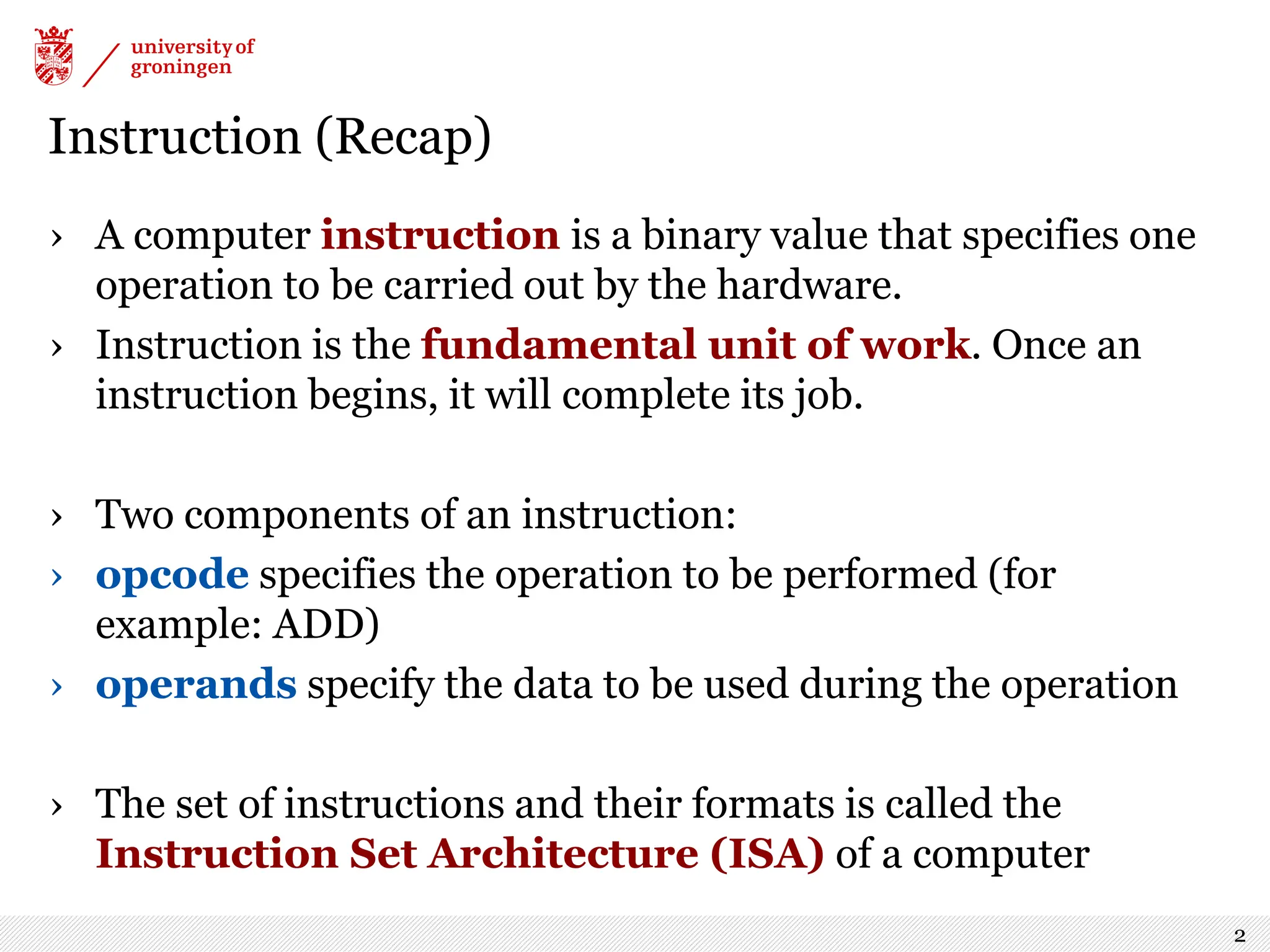
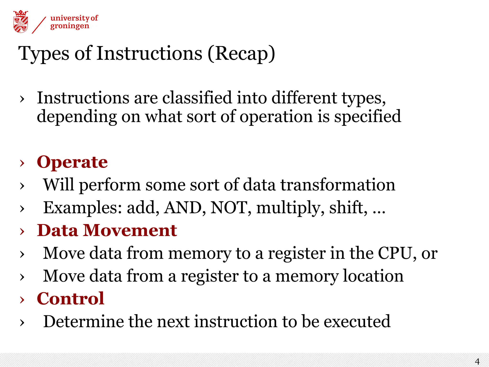
The document provides an overview of the LC-3 computer architecture, focusing on its instruction set and classification of instructions into types such as operate, data movement, and control instructions. It explains the components of an instruction, various addressing modes, and the function of condition codes. Additionally, examples illustrate the functionality of different instructions, including branching and system calls for input/output operations.
![LC-3 Instruction (Recap) › LC-3 has a four-bit opcode, bits [15:12] -- up to 16 different operations › LC-3 has eight CPU registers. Registers are used as operands for instructions -- each operand requires 3 bits to specify which register › Example: ADD instruction, opcode = 0001 “Add the contents of R2 (010) to the contents of R6 (110), and store the result in R6 (110).” 3](https://image.slidesharecdn.com/lecture6-240913091947-6f0f845b/75/Lecture6-pdf-computer-architecture-for-computer-science-3-2048.jpg)
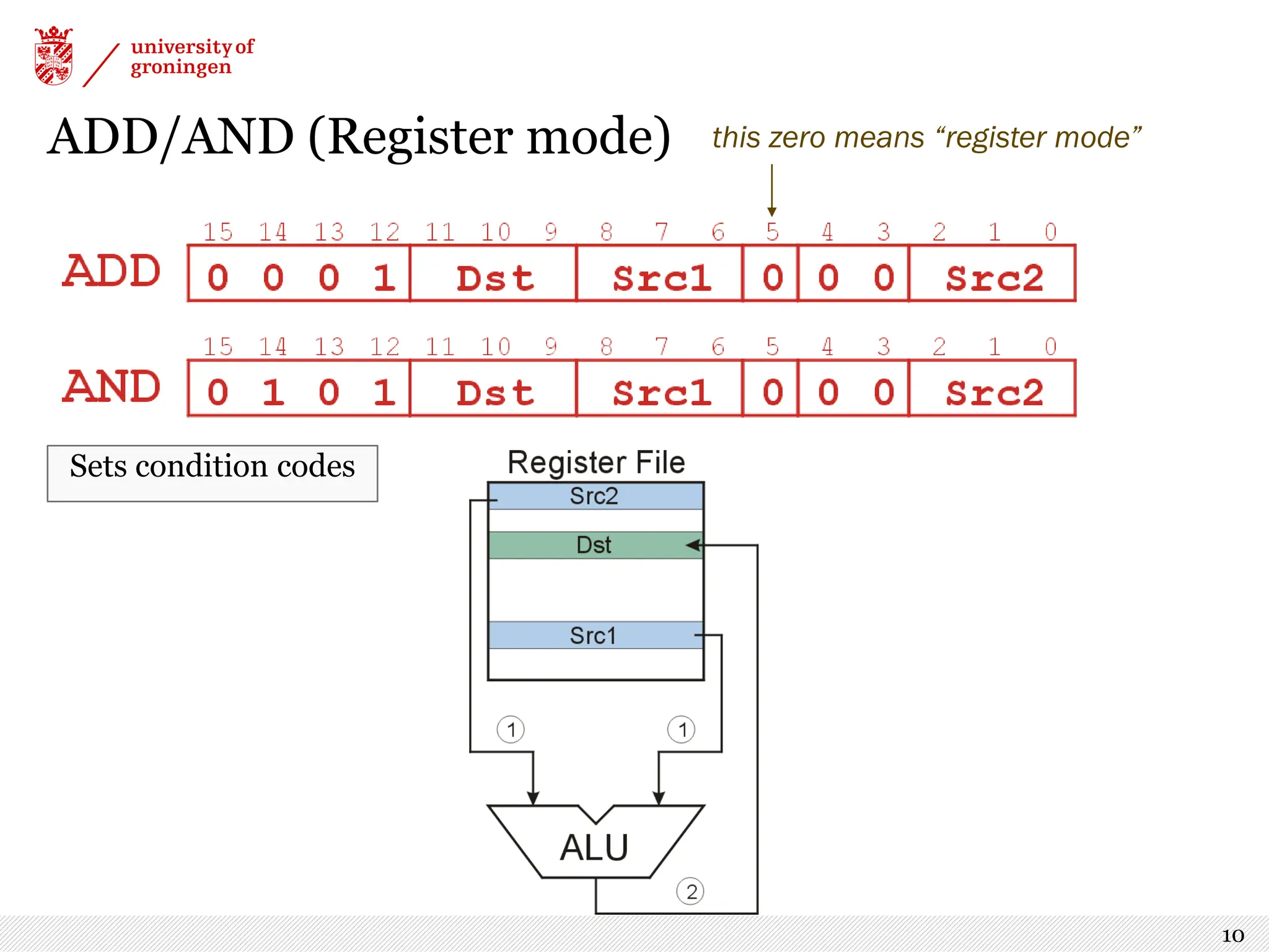
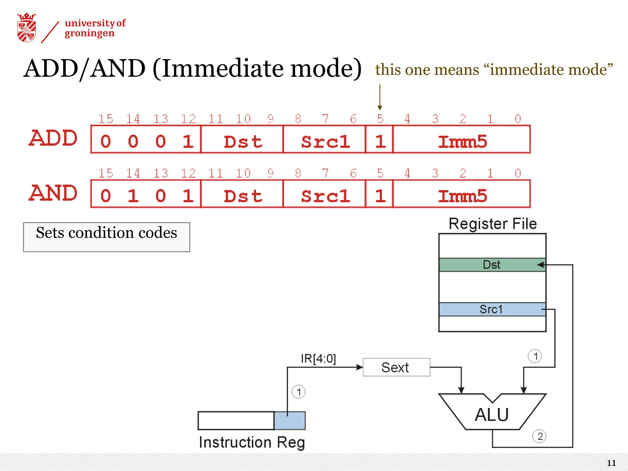
![Addressing Modes Register › First operand is always specified by a register › Second operand is a register if IR[5] = 0 Immediate › If IR[5] = 1, the second operand is specified in the instruction IR[4:0] is a 5-bit 2's complement integer, sign-extended to 16 bits 9 Q: what are the min and max values that fit in IR[4:0]?](https://image.slidesharecdn.com/lecture6-240913091947-6f0f845b/75/Lecture6-pdf-computer-architecture-for-computer-science-9-2048.jpg)
![LEA (not 100% operate) › Computes an address by adding sign-extended IR[8:0] to PC, and write the result to a register (Does not set condition codes) 14](https://image.slidesharecdn.com/lecture6-240913091947-6f0f845b/75/Lecture6-pdf-computer-architecture-for-computer-science-14-2048.jpg)
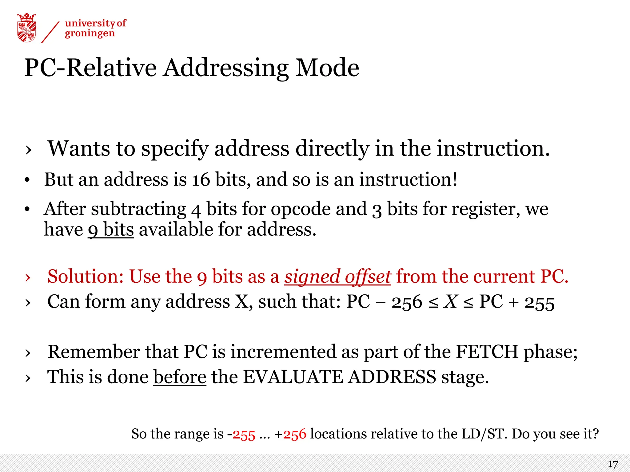
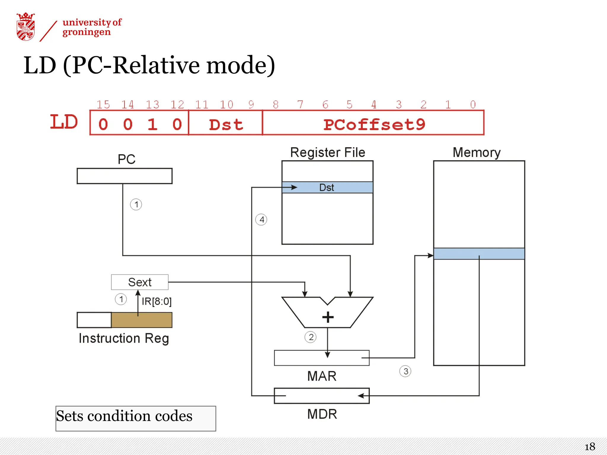
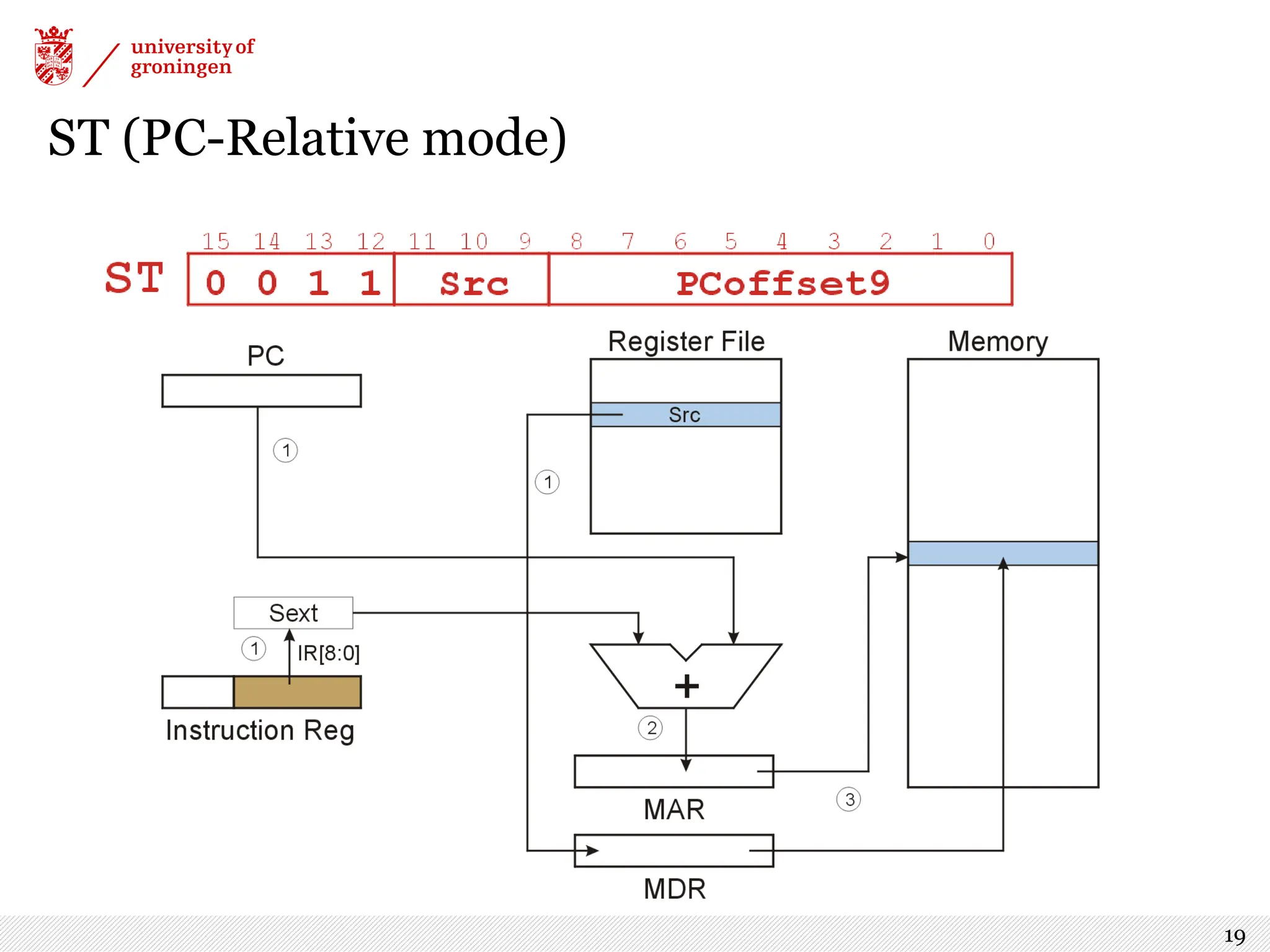
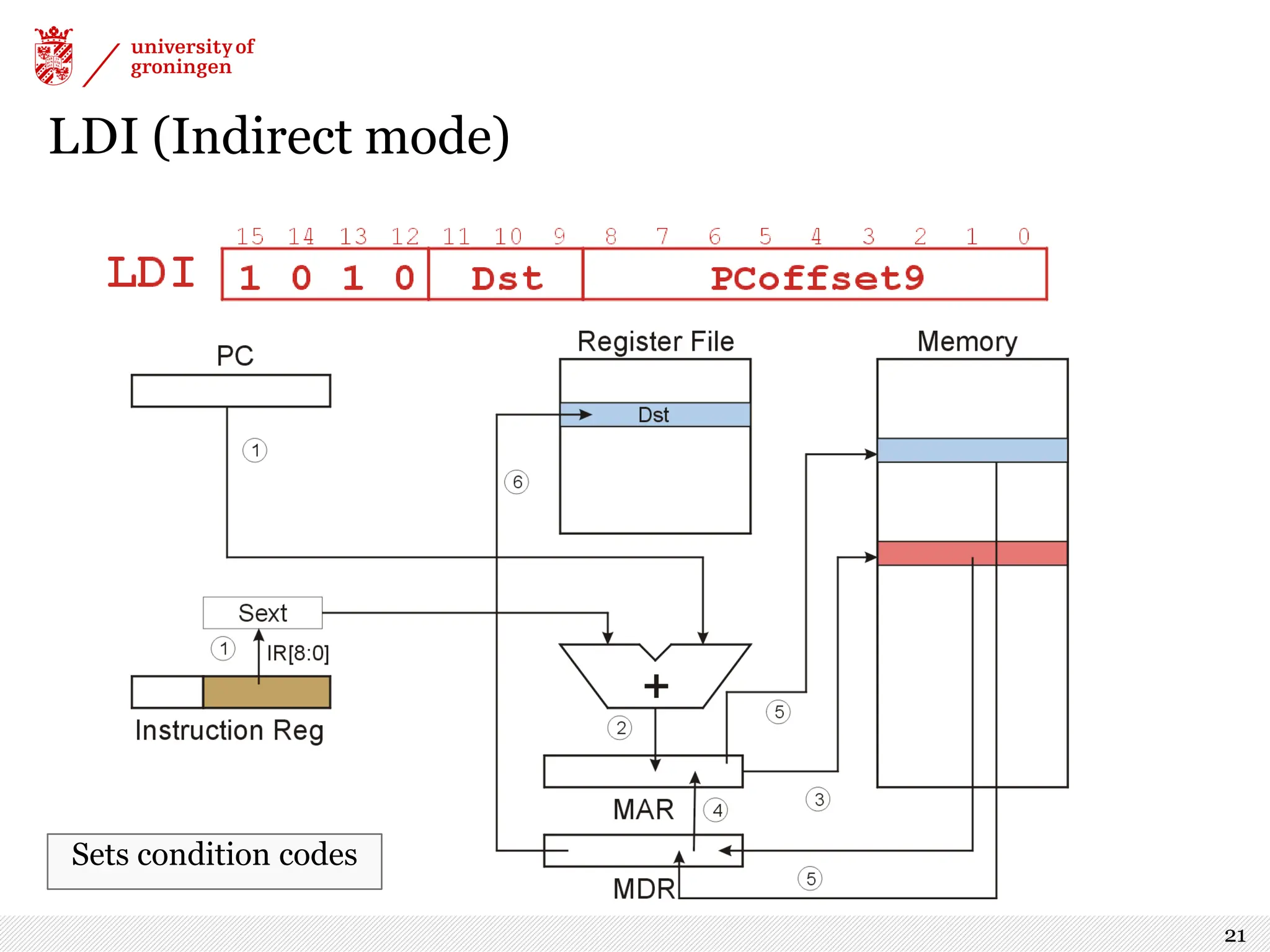
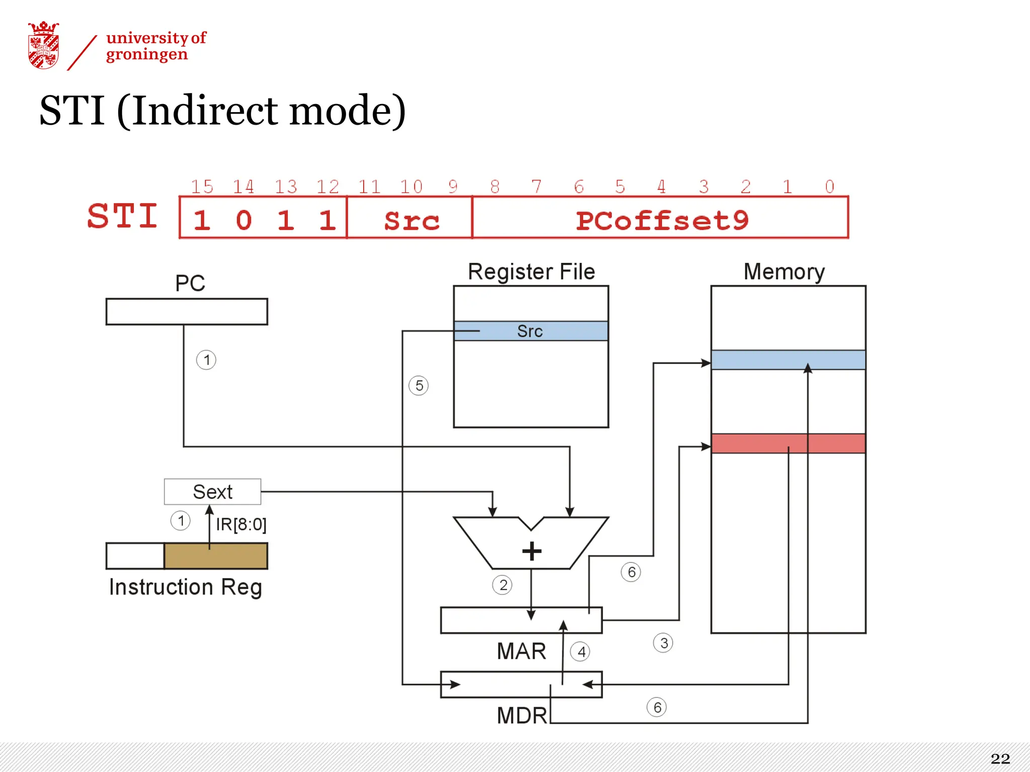
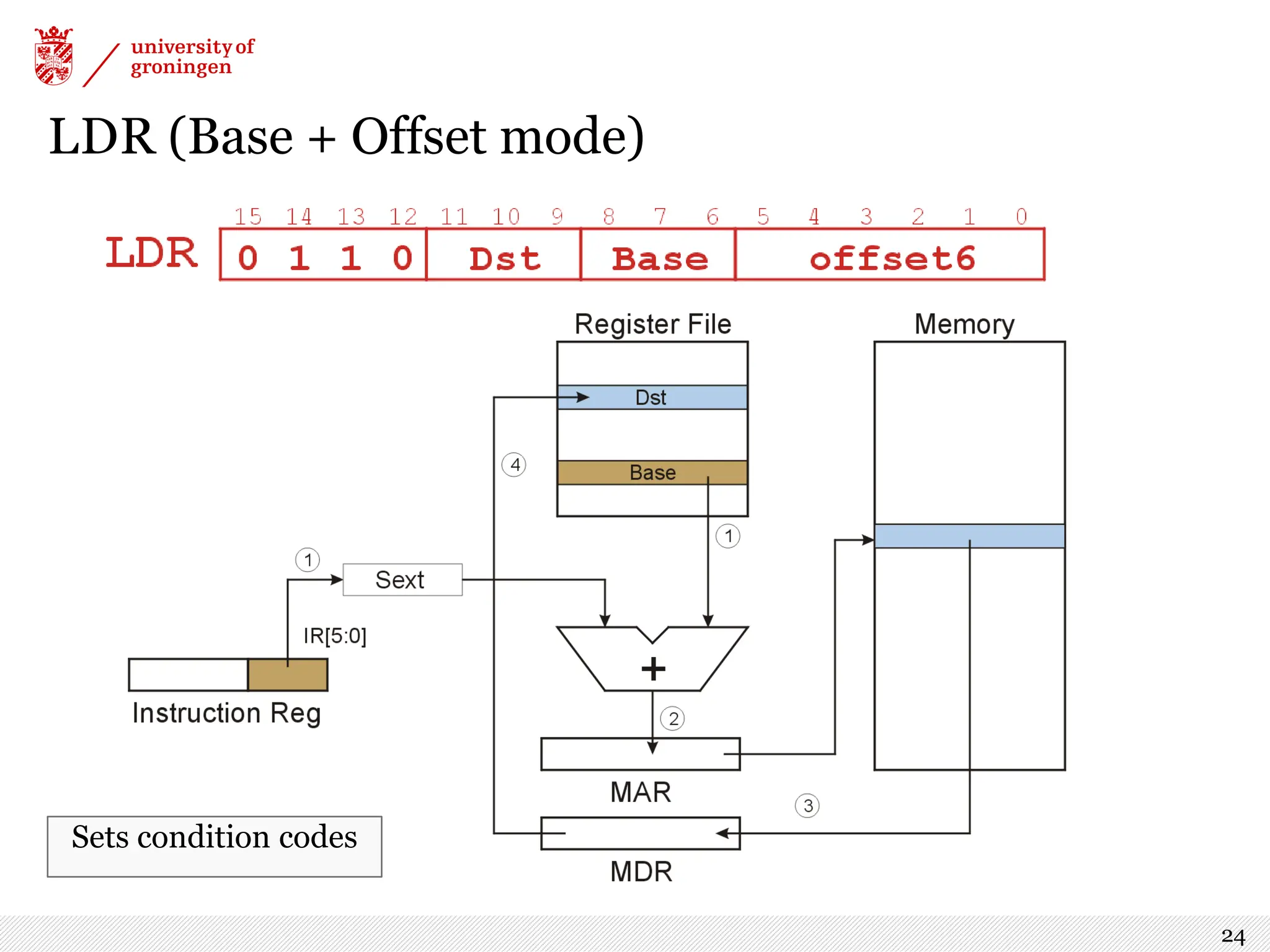
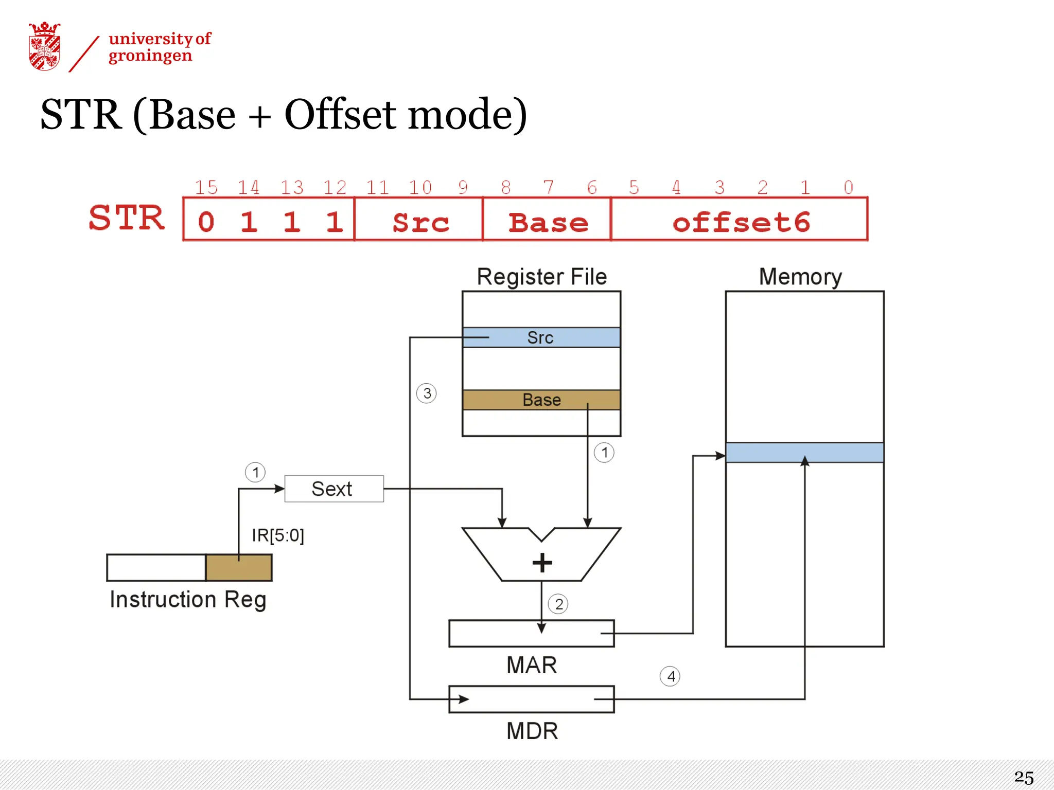
![Data Movement Instructions: Load and Store › Used to move data between memory and registers. › LOAD = from memory to register (and sets condition codes) › STORE = from register to memory › Three variants of each, with different addressing modes: PC-Relative Compute address by adding an offset IR[8:0] to the PC Indirect Load an address from a memory location Base+Offset Compute address by adding an offset IR[5:0] to a register 16](https://image.slidesharecdn.com/lecture6-240913091947-6f0f845b/75/Lecture6-pdf-computer-architecture-for-computer-science-16-2048.jpg)
![Indirect Addressing Mode › With PC-relative mode, can only address data within 256 words of the instruction. What about the rest of memory? › Solution #1: Read address from a memory location, then load/store to that address (1) Compute PC + IR[8:0] (just like PC-Relative), put in MAR (2)Load from that address into MDR (3)Move data from MDR into MAR (4)Perform load/store 20](https://image.slidesharecdn.com/lecture6-240913091947-6f0f845b/75/Lecture6-pdf-computer-architecture-for-computer-science-20-2048.jpg)
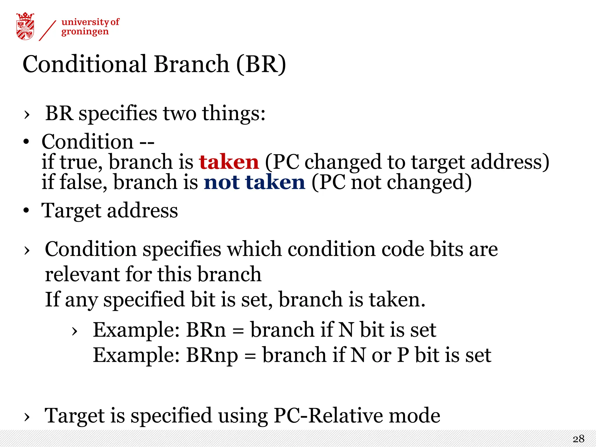
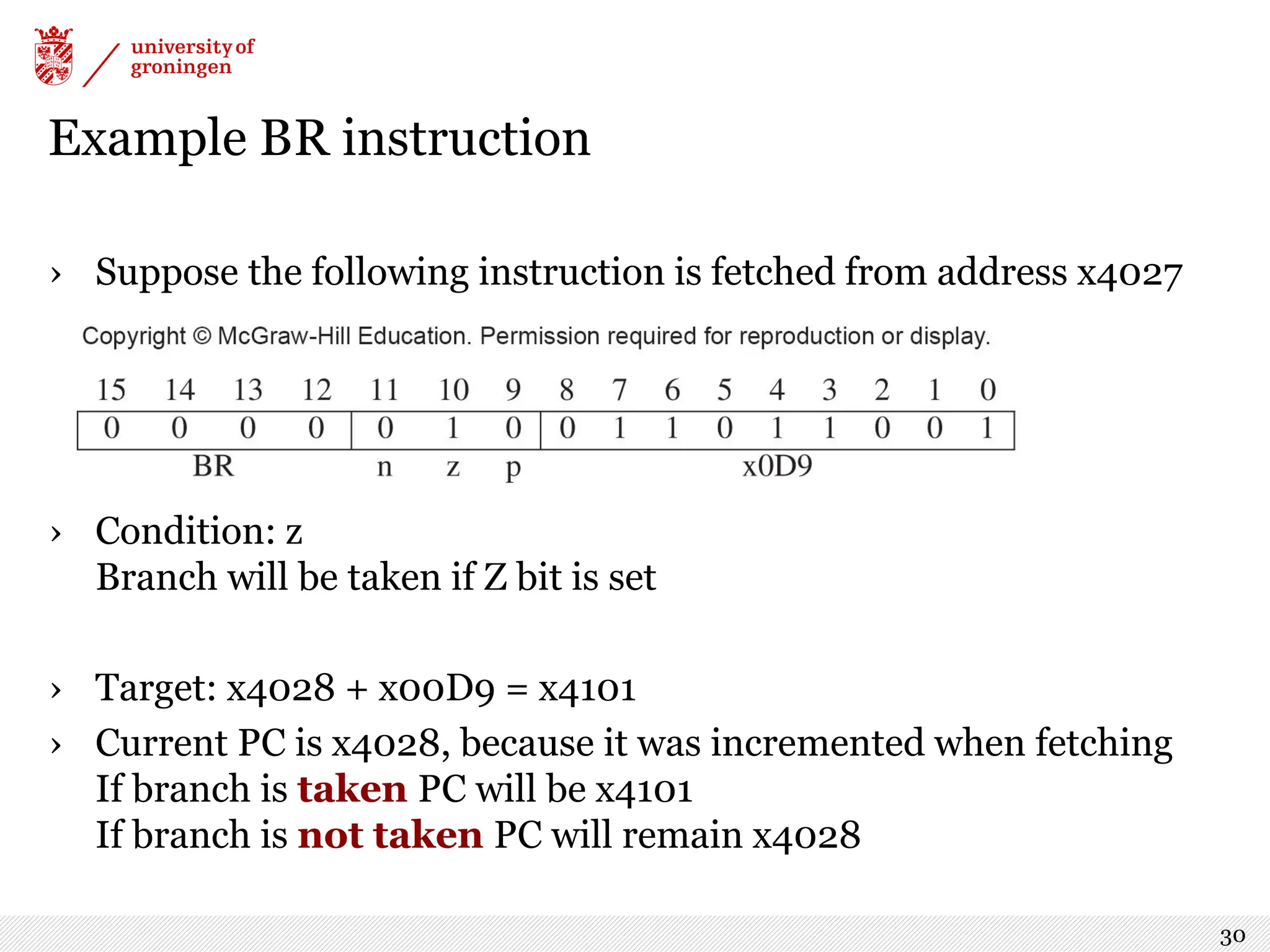
![BR Remember that PC has already been incremented in Fetch phase. PCMUX chooses either the current PC if not taken, or PC +offset if taken. Logic: (IR[11] and N) or (IR[10] and Z) or (IR[9] and P) 29](https://image.slidesharecdn.com/lecture6-240913091947-6f0f845b/75/Lecture6-pdf-computer-architecture-for-computer-science-29-2048.jpg)
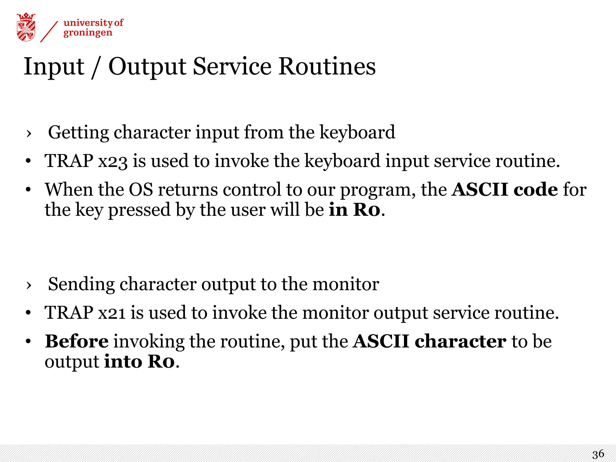
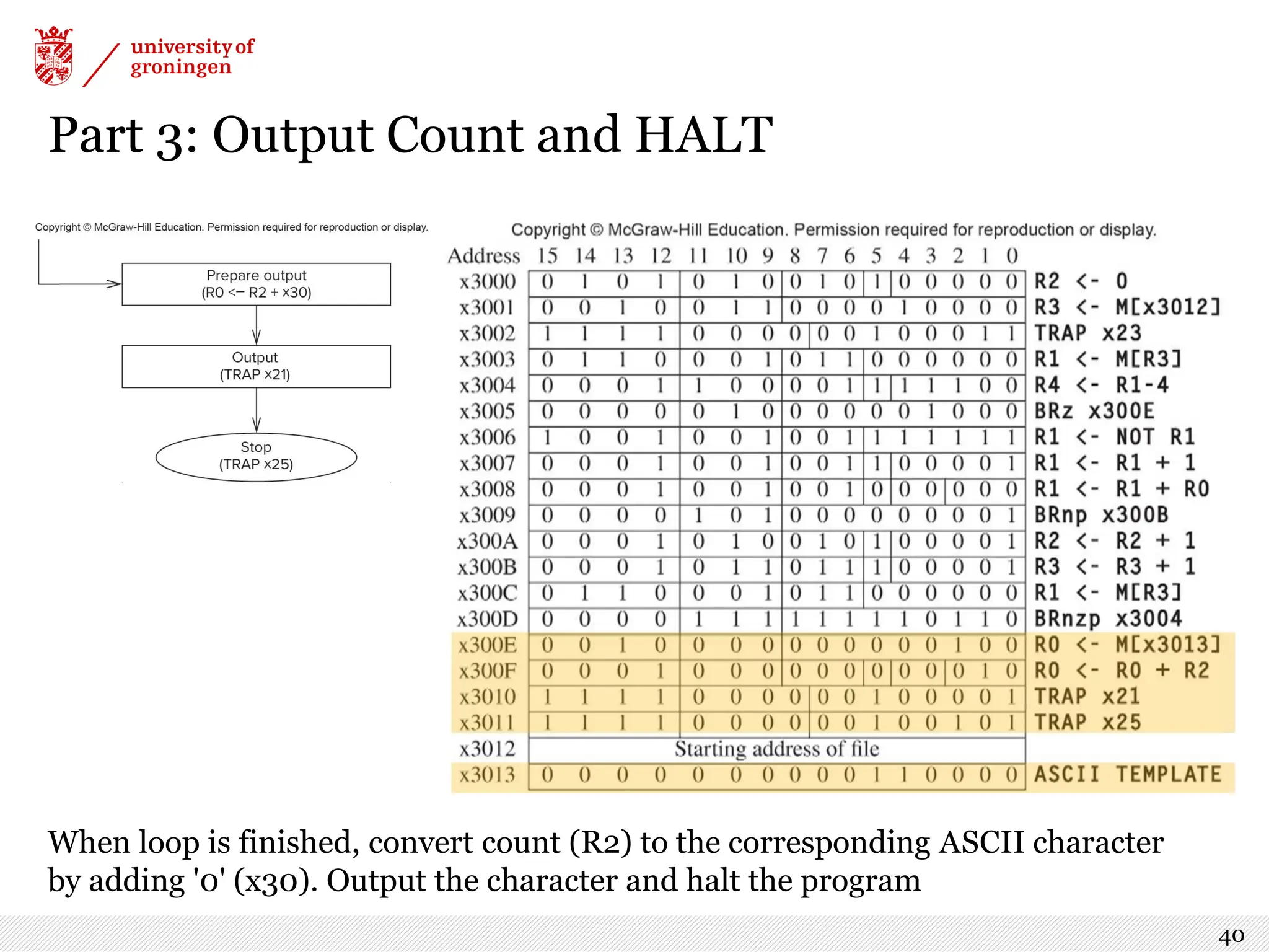
![TRAP: Invoke a System Service Routine › The TRAP instruction is used to give control to the operating system to perform a task that user code is not allowed to do. The details will be explained in Chapter 9 › For now, you just need to know that bits [7:0] hold a "trap vector" -- a unique code that specifies the service routine. The service routines used in this part of the course are: trapvector service routine x23 Input a character from the keyboard x21 Output a character to the monitor x25 Halt the processor 35](https://image.slidesharecdn.com/lecture6-240913091947-6f0f845b/75/Lecture6-pdf-computer-architecture-for-computer-science-35-2048.jpg)