Network Architecture Networkcommunications - a complex task To deal with this complexity… SIMPLIFY comm task divided into modules modules arranged in layers each layer performs a subset of comm function Forms a Network Architecture • multiple layers • each layer has one/more Protocols • protocols perform specific comm tasks • provide/obtain services to/from higher/lower layer 2
3.
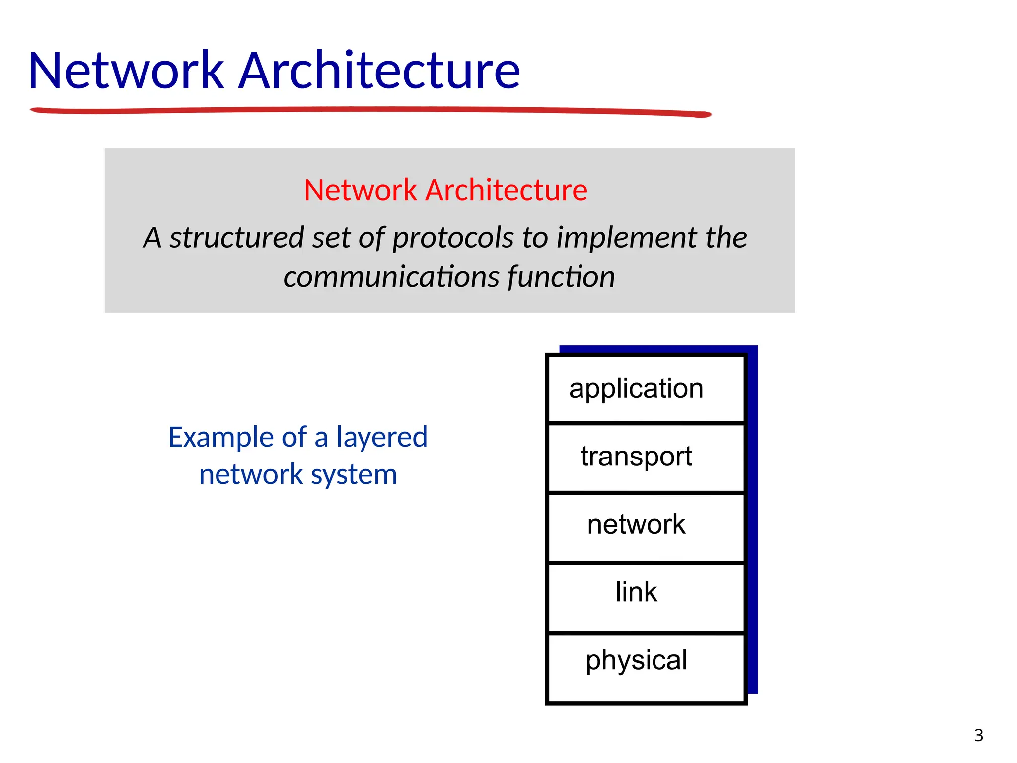
Example of alayered network system Network Architecture Network Architecture A structured set of protocols to implement the communications function application transport network link physical 3
4.
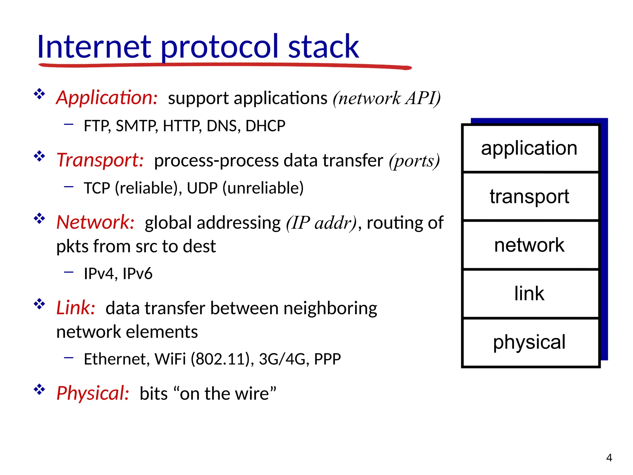
Internet protocol stack Application: support applications (network API) - FTP, SMTP, HTTP, DNS, DHCP Transport: process-process data transfer (ports) - TCP (reliable), UDP (unreliable) Network: global addressing (IP addr), routing of pkts from src to dest - IPv4, IPv6 Link: data transfer between neighboring network elements - Ethernet, WiFi (802.11), 3G/4G, PPP Physical: bits “on the wire” application transport network link physical 4
5.
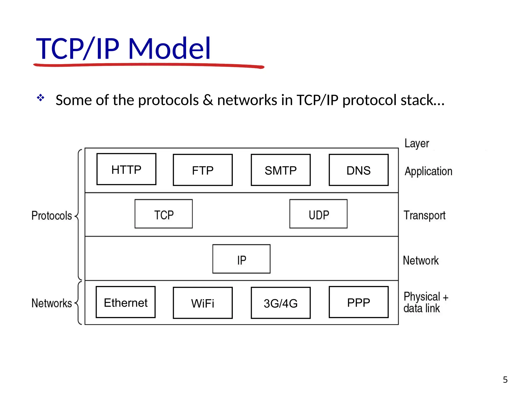
TCP/IP Model Someof the protocols & networks in TCP/IP protocol stack… 5 Ethernet WiFi PPP 3G/4G HTTP FTP SMTP DNS
6.
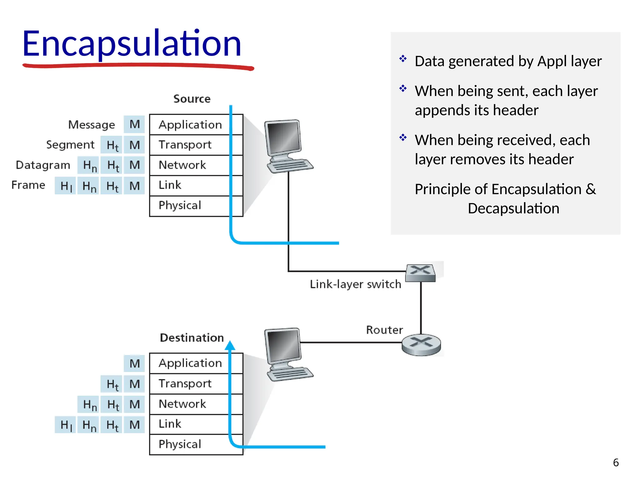
Encapsulation 6 Data generatedby Appl layer When being sent, each layer appends its header When being received, each layer removes its header Principle of Encapsulation & Decapsulation
7.
Why Layered Architecture Network Architecture - layered architecture provides modularity • changes in one layer do not require changes in other layers • simplifies system maintenance & upgradation facilitates process of network evolution • allows to change/improve underlying technologies, with increase in application demands 7
8.
Some network apps e-mail web surfing search engine P2P file sharing text messaging social networking remote login streaming stored video (YouTube, Netflix) IP radio,TV multi-user N/W games voice over IP (Skype, viber) real-time video conferencing ….. 8 How these appls are created…
9.
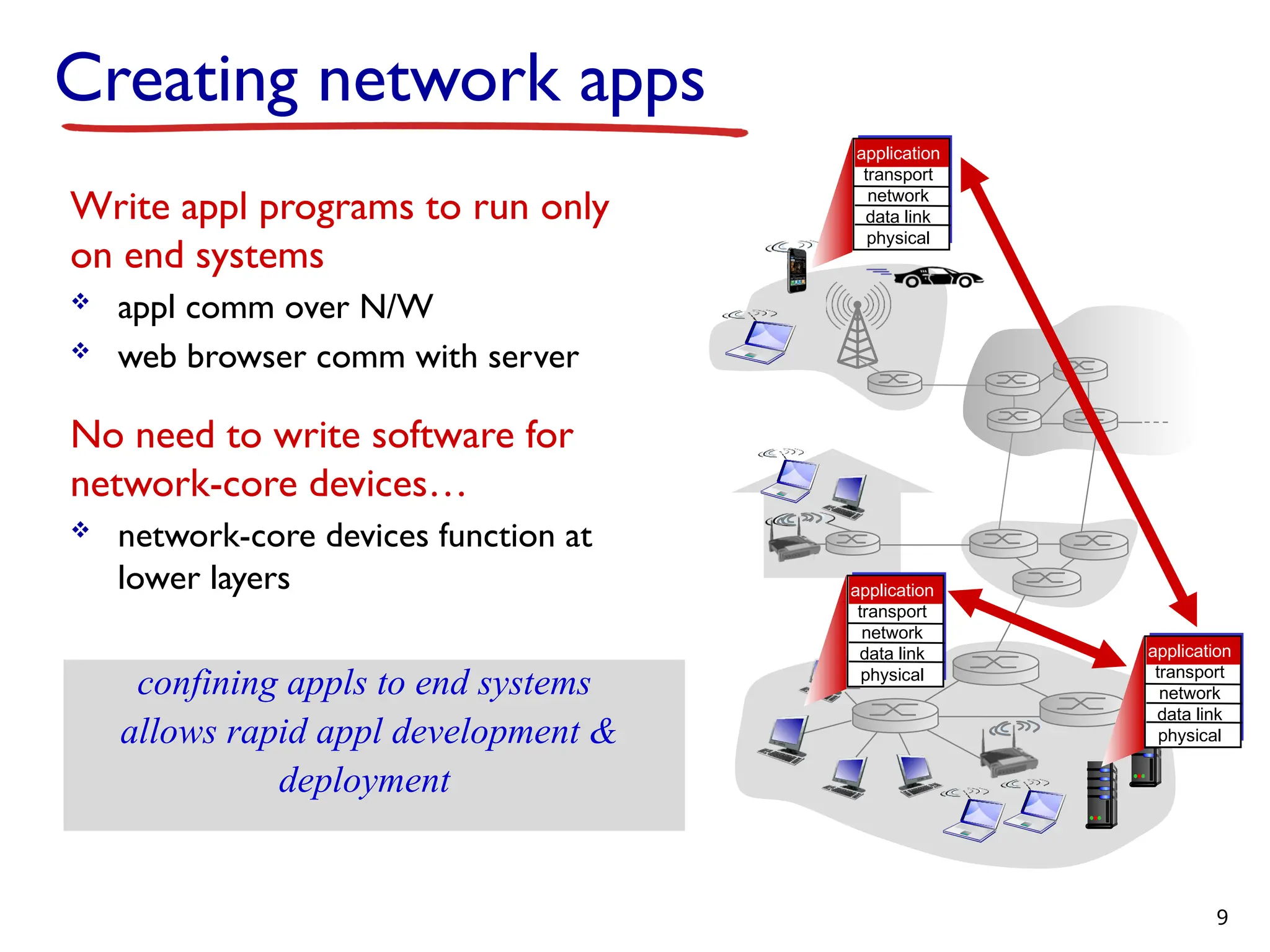
Creating network apps Writeappl programs to run only on end systems appl comm over N/W web browser comm with server No need to write software for network-core devices… network-core devices function at lower layers confining appls to end systems allows rapid appl development & deployment application transport network data link physical application transport network data link physical application transport network data link physical 9
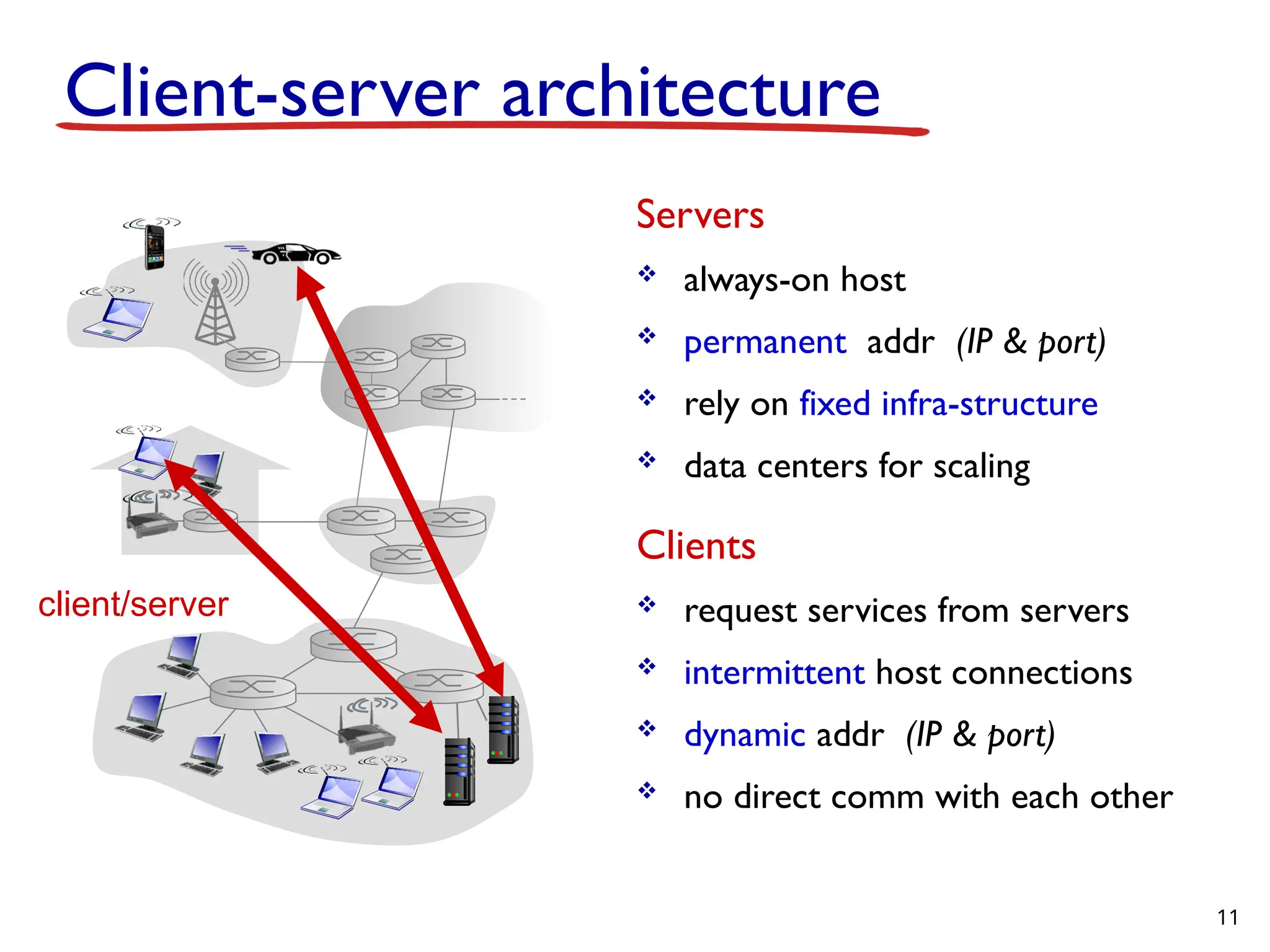
Client-server architecture Servers always-onhost permanent addr (IP & port) rely on fixed infra-structure data centers for scaling Clients request services from servers intermittent host connections dynamic addr (IP & port) no direct comm with each other client/server 11
12.
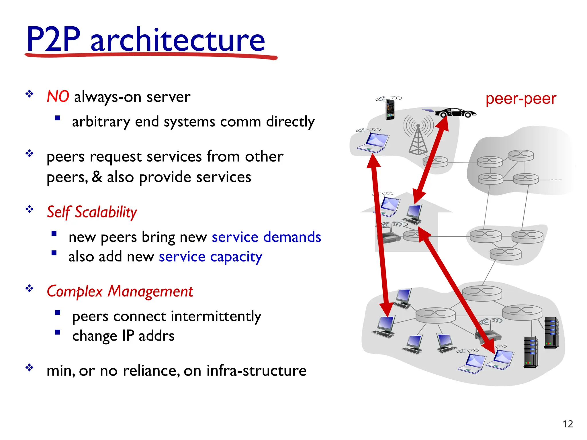
P2P architecture NOalways-on server arbitrary end systems comm directly peers request services from other peers, & also provide services Self Scalability new peers bring new service demands also add new service capacity Complex Management peers connect intermittently change IP addrs min, or no reliance, on infra-structure peer-peer 12
13.
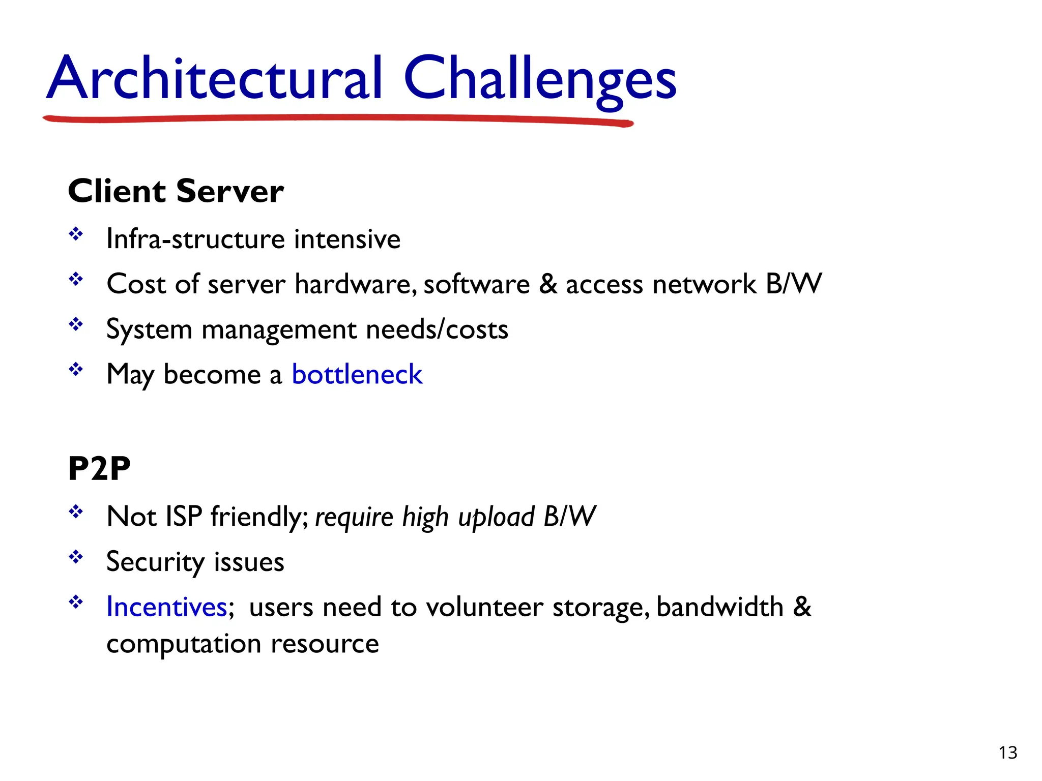
Architectural Challenges Client Server Infra-structure intensive Cost of server hardware, software & access network B/W System management needs/costs May become a bottleneck P2P Not ISP friendly; require high upload B/W Security issues Incentives; users need to volunteer storage, bandwidth & computation resource 13
14.
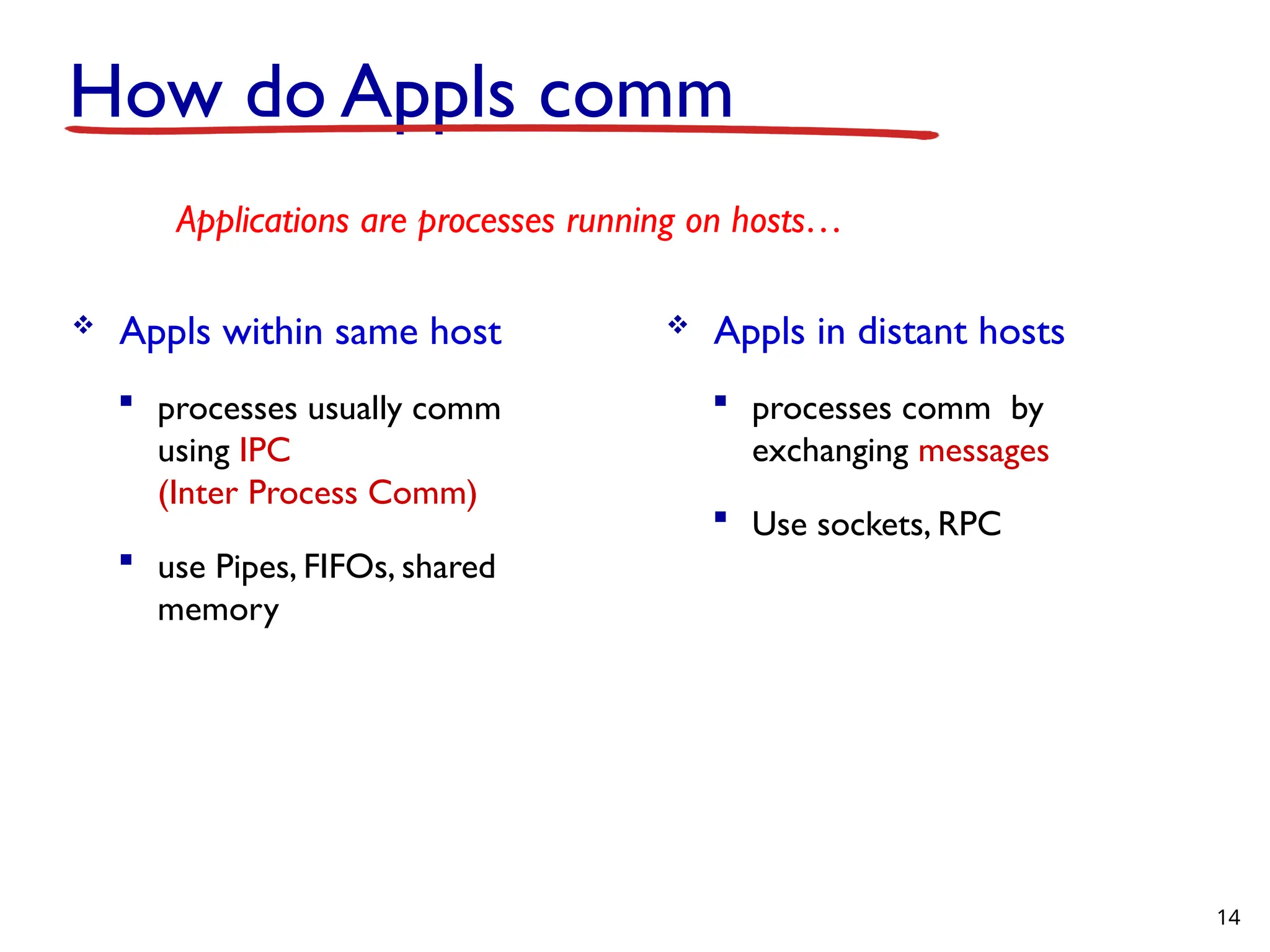
How do Applscomm Appls within same host processes usually comm using IPC (Inter Process Comm) use Pipes, FIFOs, shared memory 14 Applications are processes running on hosts… Appls in distant hosts processes comm by exchanging messages Use sockets, RPC
15.
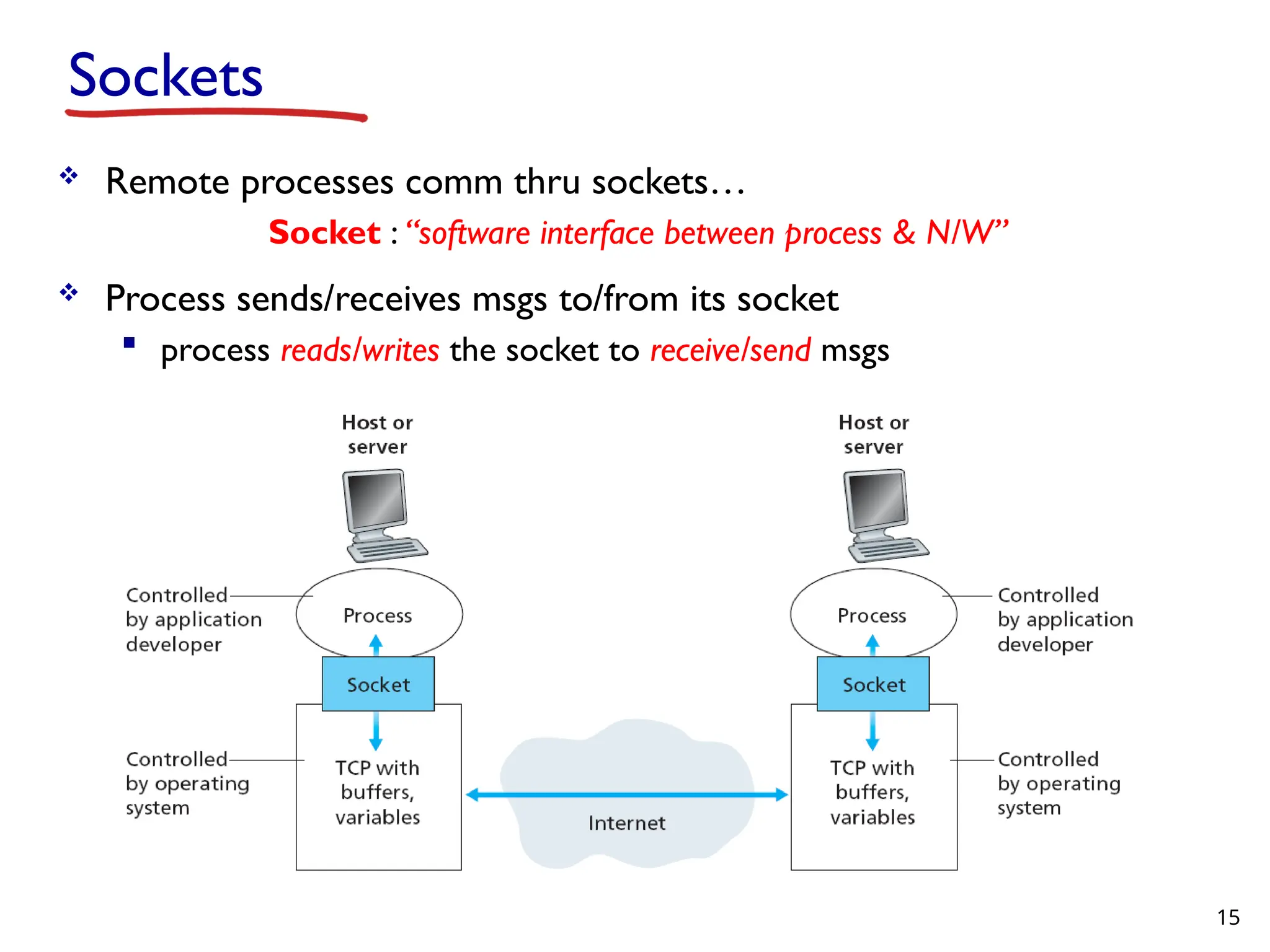
Remote processescomm thru sockets… Socket : “software interface between process & N/W” Process sends/receives msgs to/from its socket process reads/writes the socket to receive/send msgs 15 Sockets
16.
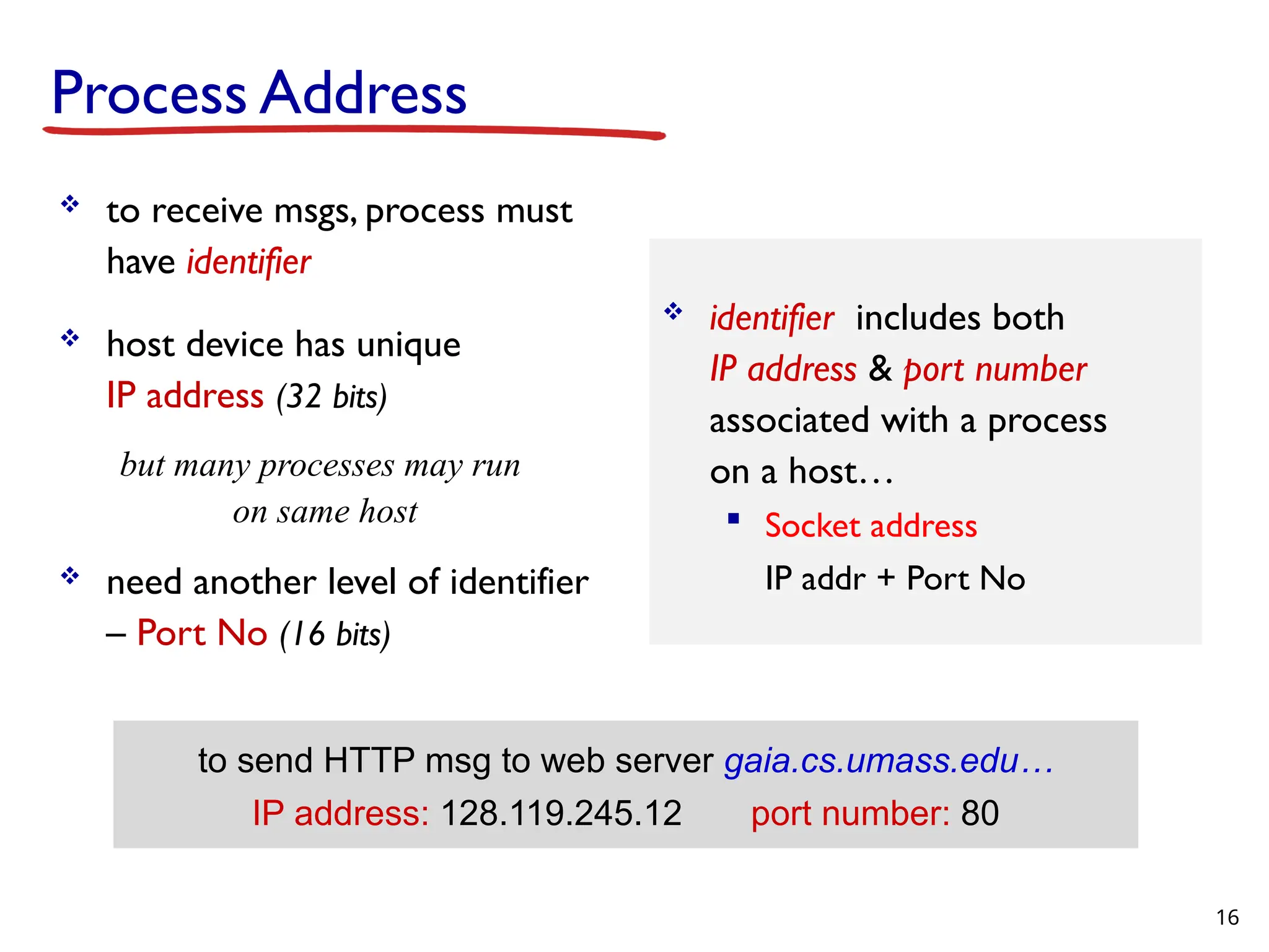
Process Address toreceive msgs, process must have identifier host device has unique IP address (32 bits) but many processes may run on same host need another level of identifier – Port No (16 bits) identifier includes both IP address & port number associated with a process on a host… Socket address IP addr + Port No 16 to send HTTP msg to web server gaia.cs.umass.edu… IP address: 128.119.245.12 port number: 80
17.
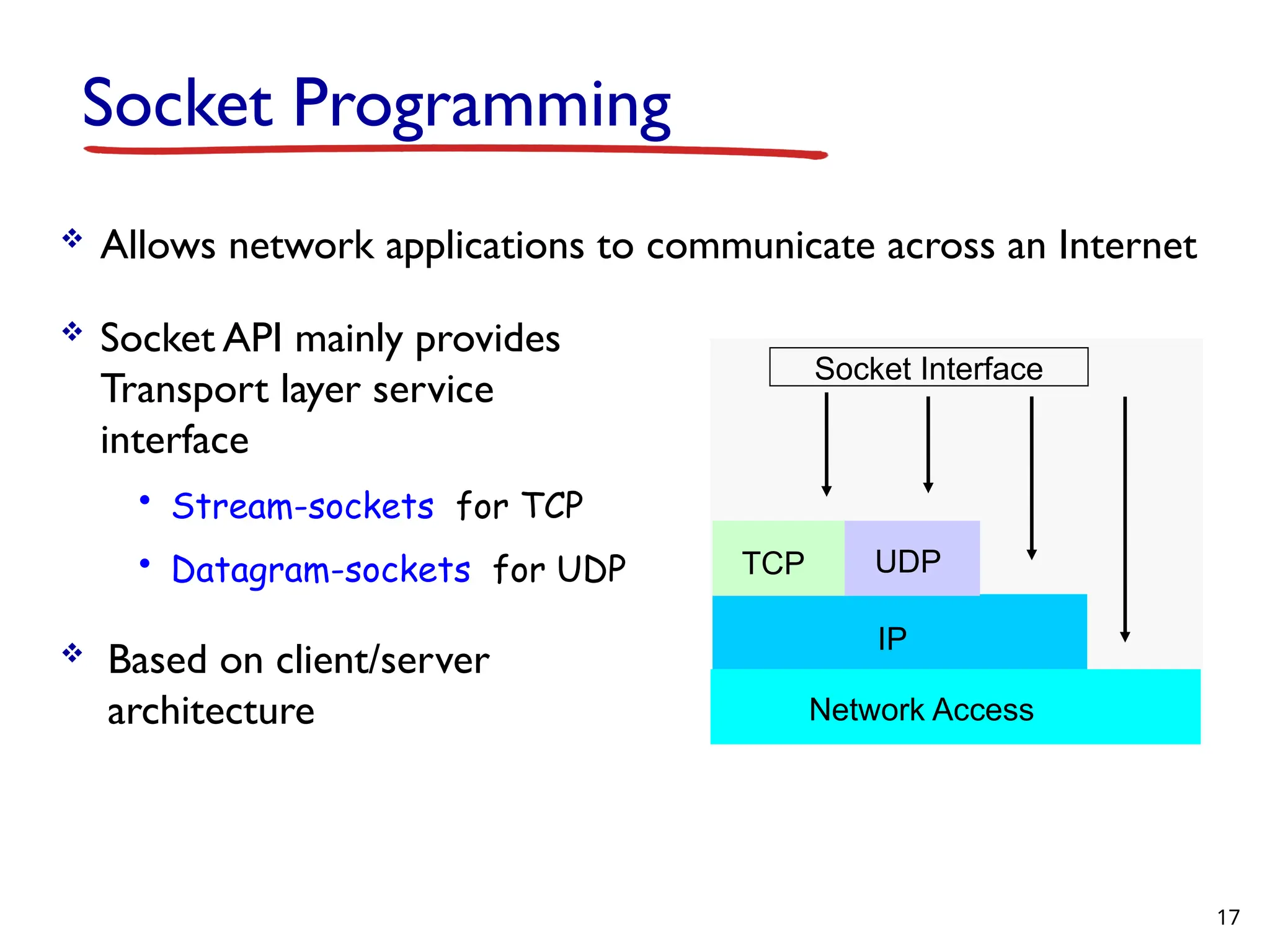
Socket Programming Allowsnetwork applications to communicate across an Internet Socket API mainly provides Transport layer service interface • Stream-sockets for TCP • Datagram-sockets for UDP Based on client/server architecture Socket Interface TCP UDP IP Network Access 17
18.
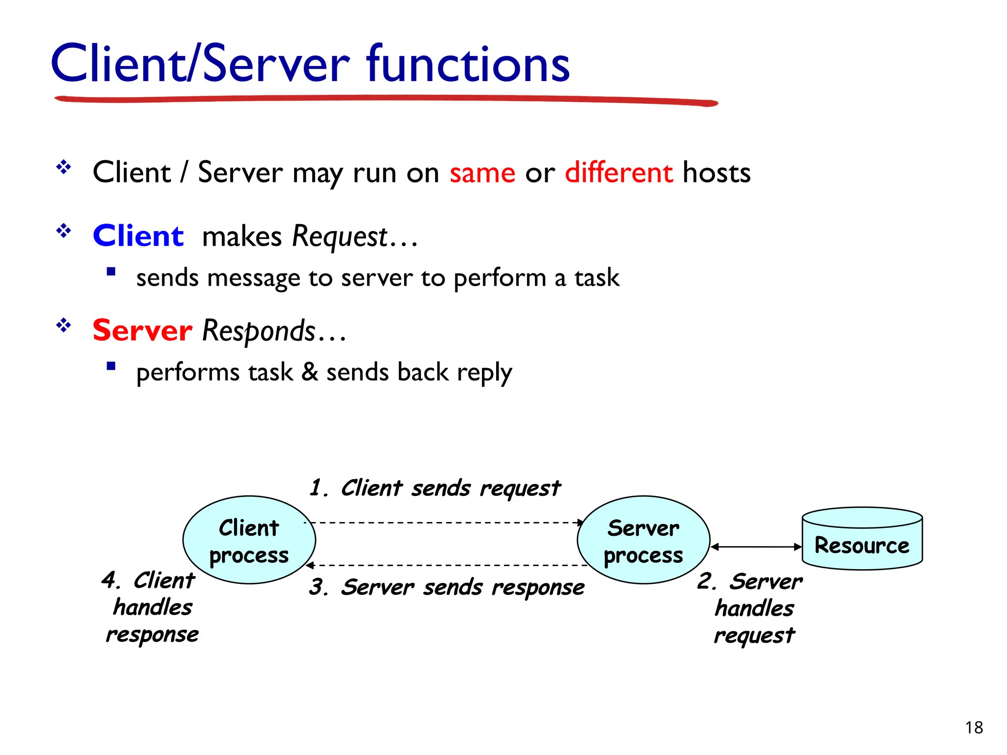
Client/Server functions Client/ Server may run on same or different hosts Client makes Request… sends message to server to perform a task Server Responds… performs task & sends back reply Client process Server process 1. Client sends request 2. Server handles request 3. Server sends response 4. Client handles response Resource 18
19.
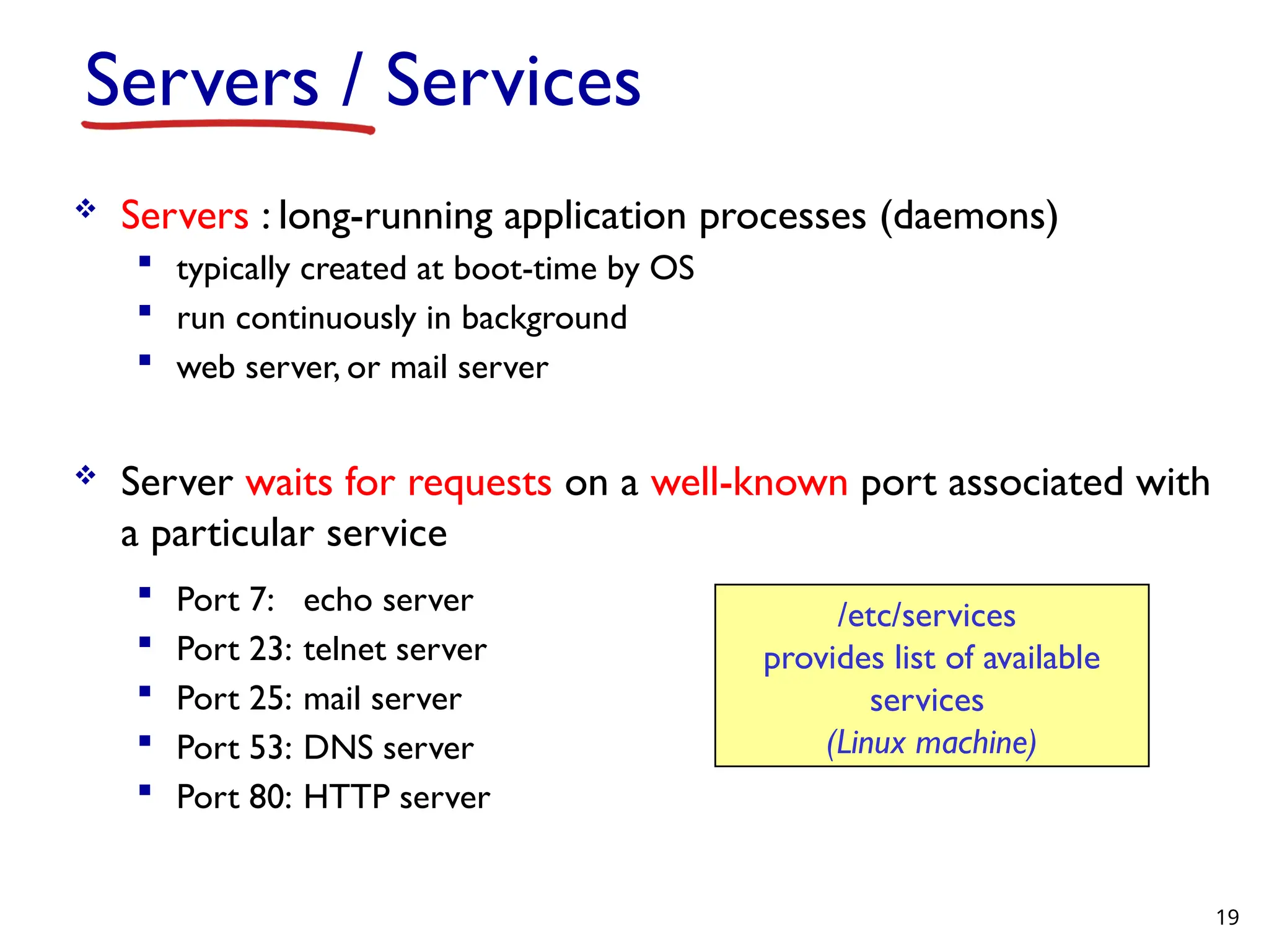
Servers / Services Servers : long-running application processes (daemons) typically created at boot-time by OS run continuously in background web server, or mail server Server waits for requests on a well-known port associated with a particular service Port 7: echo server Port 23: telnet server Port 25: mail server Port 53: DNS server Port 80: HTTP server /etc/services provides list of available services (Linux machine) 19
20.
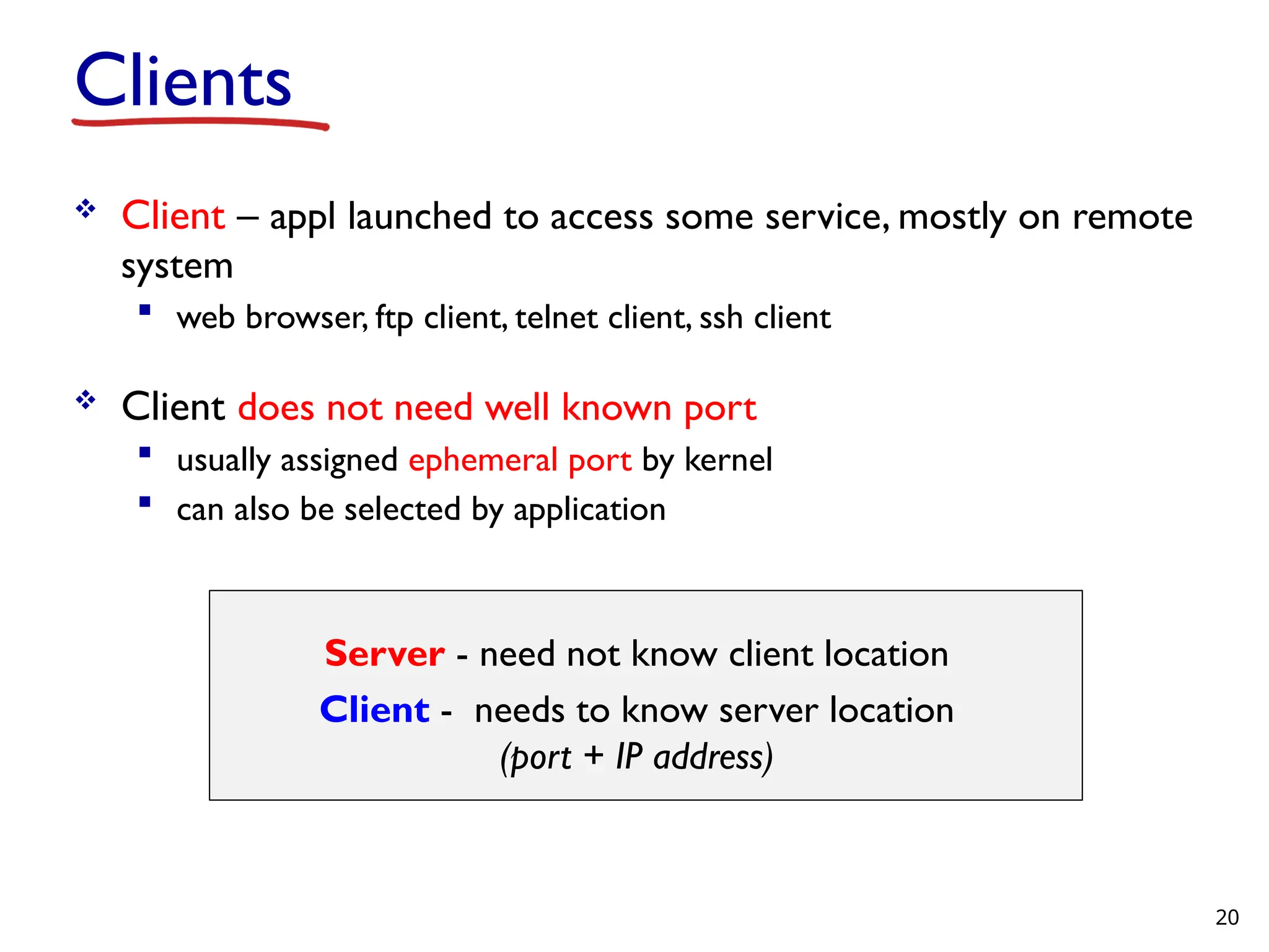
Clients Client –appl launched to access some service, mostly on remote system web browser, ftp client, telnet client, ssh client Client does not need well known port usually assigned ephemeral port by kernel can also be selected by application Server - need not know client location Client - needs to know server location (port + IP address) 20
21.
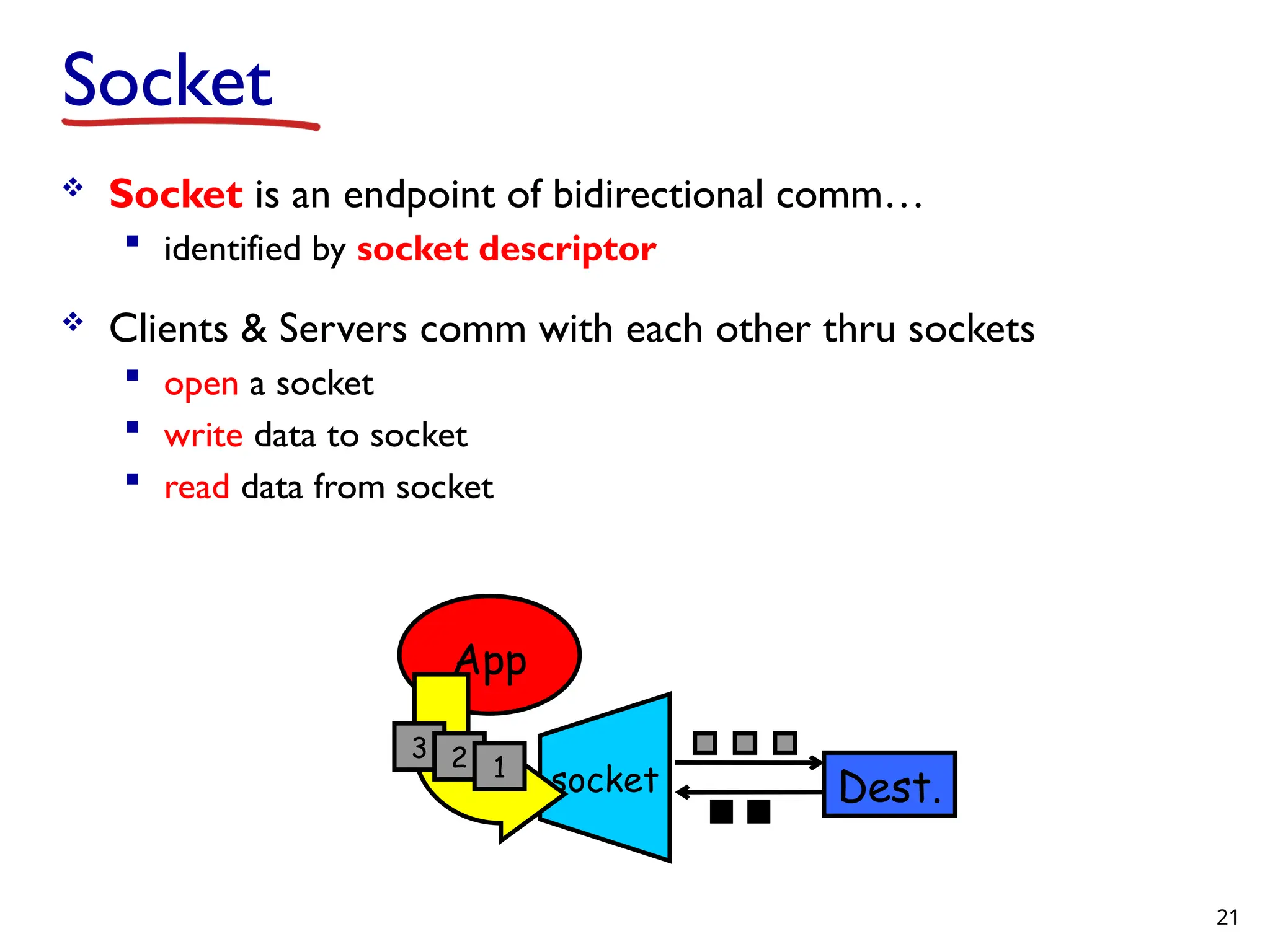
Socket Socket isan endpoint of bidirectional comm… identified by socket descriptor Clients & Servers comm with each other thru sockets open a socket write data to socket read data from socket App socket 3 2 1 Dest. 21
22.
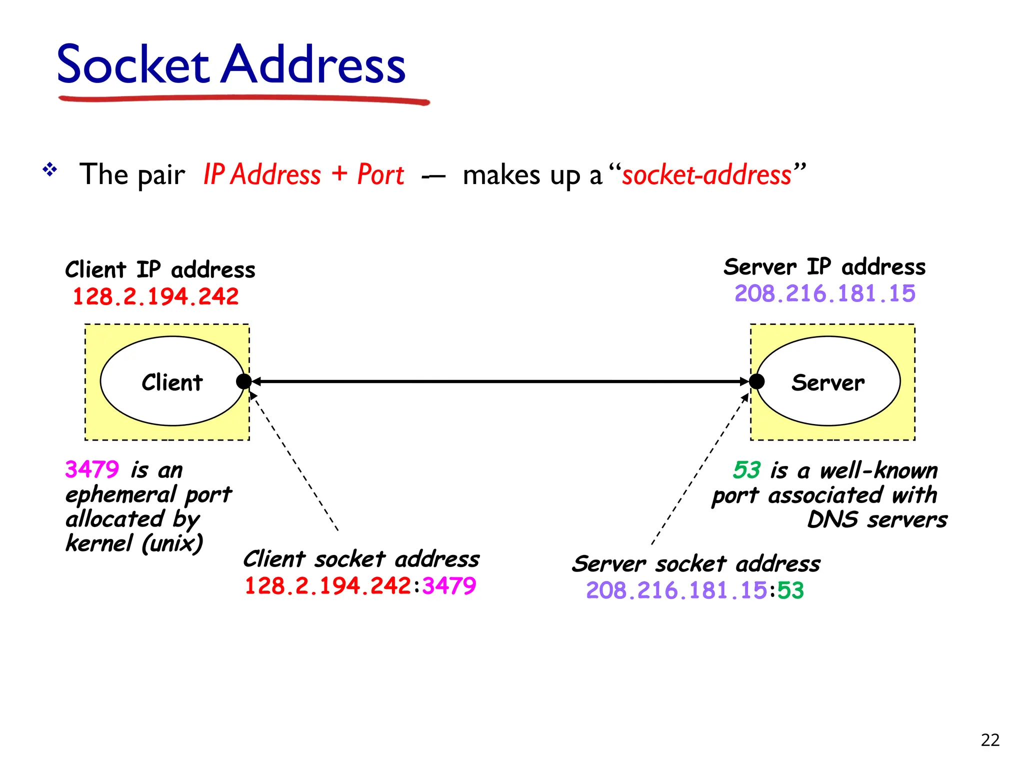
Socket Address Thepair IP Address + Port -– makes up a “socket-address” Server Client Client socket address 128.2.194.242:3479 Server socket address 208.216.181.15:53 Client IP address 128.2.194.242 Server IP address 208.216.181.15 3479 is an ephemeral port allocated by kernel (unix) 53 is a well-known port associated with DNS servers 22
23.
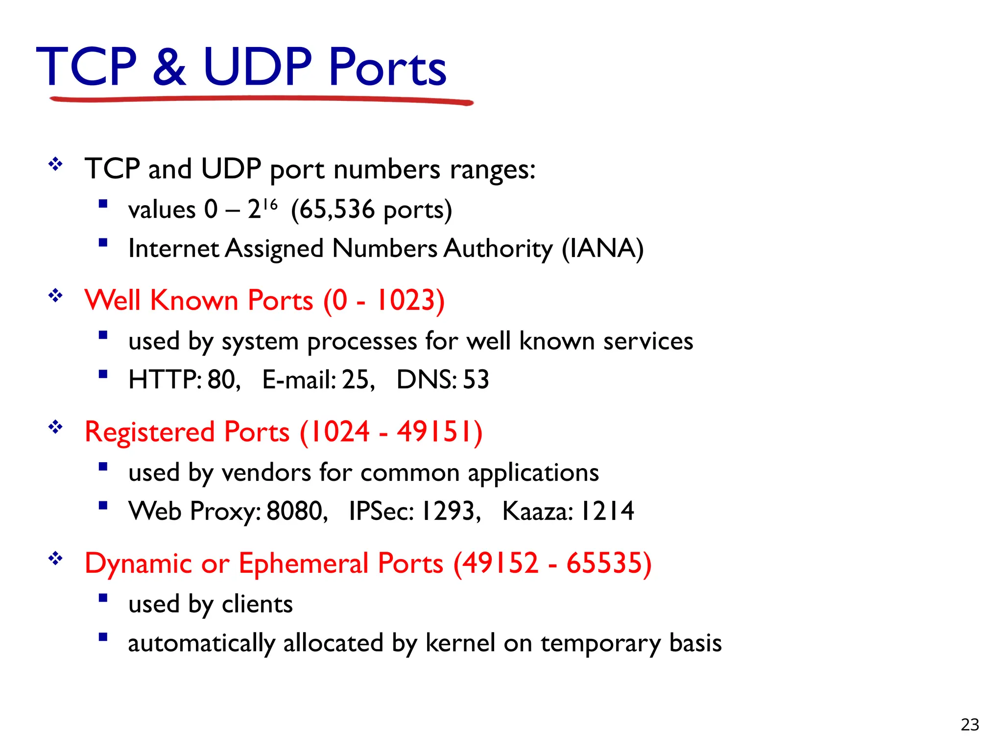
TCP & UDPPorts TCP and UDP port numbers ranges: values 0 – 216 (65,536 ports) Internet Assigned Numbers Authority (IANA) Well Known Ports (0 - 1023) used by system processes for well known services HTTP: 80, E-mail: 25, DNS: 53 Registered Ports (1024 - 49151) used by vendors for common applications Web Proxy: 8080, IPSec: 1293, Kaaza: 1214 Dynamic or Ephemeral Ports (49152 - 65535) used by clients automatically allocated by kernel on temporary basis 23
Editor's Notes
#2 The long-distance carrier system provided in the United States and throughout the world was designed to transmit voice signals over high-capacity transmission links, such as optical fiber, coaxial cable, and microwave. Part of the evolution of these telecommunications networks to digital technology has been the adoption of synchronous TDM transmission structures. In the United States, AT&T developed a hierarchy of TDM structures of various capacities; this structure is used in Canada and Japan as well as the United States. A similar, but unfortunately not identical, hierarchy has been adopted internationally under the auspices of ITU-T. The basis of the TDM hierarchy (in North America and Japan) is the DS-1 transmission format. The same DS-1 format is used to provide both multiplexed voice and digital data services. Above the DS-1 data rate of 1.544 Mbps, higher-level multiplexing is achieved by interleaving bits from DS-1 inputs. For example, the DS-2 transmission system combines four DS-1 inputs into a 6.312-Mbps stream. Data from the four sources are interleaved 12 bits at a time. Note that 1.544 4 = 6.176 Mbps. The remaining capacity is used for framing and control bits.
#7 The long-distance carrier system provided in the United States and throughout the world was designed to transmit voice signals over high-capacity transmission links, such as optical fiber, coaxial cable, and microwave. Part of the evolution of these telecommunications networks to digital technology has been the adoption of synchronous TDM transmission structures. In the United States, AT&T developed a hierarchy of TDM structures of various capacities; this structure is used in Canada and Japan as well as the United States. A similar, but unfortunately not identical, hierarchy has been adopted internationally under the auspices of ITU-T. The basis of the TDM hierarchy (in North America and Japan) is the DS-1 transmission format. The same DS-1 format is used to provide both multiplexed voice and digital data services. Above the DS-1 data rate of 1.544 Mbps, higher-level multiplexing is achieved by interleaving bits from DS-1 inputs. For example, the DS-2 transmission system combines four DS-1 inputs into a 6.312-Mbps stream. Data from the four sources are interleaved 12 bits at a time. Note that 1.544 4 = 6.176 Mbps. The remaining capacity is used for framing and control bits.