Download to read offline
![Ms.Shankari N al. Int. Journal of Engineering Research and Application www.ijera.com ISSN : 2248-9622, Vol. 6, Issue 5, ( Part -6) May 2016, pp.43-47 www.ijera.com 43 | P a g e Hard Decision Viterbi Decoder: Implementation on FPGA and Comparison of Resource Utilization on Different FPGA Devices Ms. Shankari N*, Mrs. Shrividya G** *M.Tech student, Department of ECE, NMAM Institute of Technology, Nitte, Karkala, India ** Associate Professor, Department of ECE, NMAM Institute of Technology, Nitte, Karkala, India ABSTRACT Viterbi decoder is the most important part in receiver section of wireless communication system. Viterbi algorithm is one of the most common decoding algorithms used for decoding convolutional codes. Viterbi decoder employs Maximum Likelihood technique to decode the convolutionally encoded data stream. In practice, most of the communication systems use Viterbi decoding scheme in processors. But increased interest on high speed Viterbi decoder in a single chip forced to realize with the speed of Giga-bit per second, without using memory or off-chip processors. Implementation of proposed design and realization is possible due to advanced Field Programmable Gate Array (FPGA) technologies and advanced Electronic Design Automatic (EDA) tools. This paper involves designing an optimum structure of Viterbi decoder and implementing it on different FPGA devices to compare the resource utilizations. Keywords Branch Metric (BM), Hamming Distance (HD), Path Metric (PM), Survivor path, Signal to Noise Ratio (SNR), Trace-back, Viterbi decoder. I. INTRODUCTION In wireless communication systems noise and interference level in the channel is very high. It greatly affects the Signal to Noise Ratio (SNR). Hence certain Error Detection and Correction (EDC) techniques are required to improve SNR. An error correcting code which is used in most of the communication systems is convolutional code. Most of the transmitters use convolutional encoder to add redundancy to the information being transmitted. Hence the effective technique to decode the convolutionally encoded data is Viterbi decoder. Viterbi decoder uses Viterbi algorithm to decode the data. It involves Maximum Likelihood (ML) decoding where the computational load is reduced. The algorithm will use Trellis structure [1]. The received symbol is compared with actual codewords in each transmission. The configuration of Viterbi decoder depends on encoder's code rate, constraint length and generator polynomial. The probability of error will be reduced by Viterbi decoder hence it is called Optimum Algorithm. Even-though the present information bits are corrupted by noise in the channel. Viterbi decoder is able to correct the corrupted bits or error bits due to the structure of convolutional encoded code. The decoding will start at '0' state by the assumption that encoding will start from the same state. Actually the ML decoding will be independent of initial states [4]. The ML decoding involves selection of low metric path as winning path. The winning path will have low bit error path compared to other paths. Parallel implementation of Viterbi decoder is possible [7]. There are 2 types of Viterbi decoder implementation namely hard decision Viterbi decoding and soft decision Viterbi decoding. The metric is Hamming distance metric in hard decision Viterbi decoder and Euclidean distance metric in soft decision Viterbi decoder. The implementation of hard decision Viterbi decoder involves finding Hamming distance metric and the path with lowest Hamming distance metric (cumulative metric) is called survivor path. The number of bit positions by which the received symbol and actual symbol differ is Hamming distance [5]. If Hamming distance is zero, indicate that the symbol or data is received as it is transmitted without any error. The implementation of soft decision Viterbi decoder involves finding metric used is Euclidean distance. This is squared difference between received symbol and actual symbol. In this type the received symbol is quantized into more than two levels and Euclidean distance is calculated [5]. The path with minimum Euclidean distance is considered as survivor path. Soft decision decoding will be better compared to hard decision because soft decision decoding will have more information about the received information compared to hard decision decoding. II. CONVOLUTIONAL ENCODER The type of decoders used in receiver section of any communication system depends on type of encoding scheme used in transmitter section. Most of the transmitters use convolutional encoding scheme. RESEARCH ARTICLE OPEN ACCESS](https://image.slidesharecdn.com/i060506043047-160811043646/75/Hard-Decision-Viterbi-Decoder-Implementation-on-FPGA-and-Comparison-of-Resource-Utilization-on-Different-FPGA-Devices-1-2048.jpg)
![Ms.Shankari N al. Int. Journal of Engineering Research and Application www.ijera.com ISSN : 2248-9622, Vol. 6, Issue 5, ( Part -6) May 2016, pp.43-47 www.ijera.com 44 | P a g e Fig.1. (2, 1, 7) Convolutional encoder A (2, 1, 7) convolutional encoder which is base for Viterbi decoder design is as shown in Fig.1. The output from Convolutional encoder mainly depend on generator vectors (171)o and (133)o. It also has constraint length 7 and code rate ½. Since there are 6 shift registers in designed encoder structure, state diagram involves 26 = 64 states. The state transition mainly depends on input bit (‘0’ or ‘1’). Based on input arrived into Convolutional encoder there will be two transitions from each state. Hence 64 states will have 128 transitions. The all possible state transitions are graphically represented in Fig. 2. Each state transition leads to particular output bit combinations which plays important role in decoding process. The rate of the Convolutional encoder mainly depends on number of bits inputted and number of output bits obtained. For each input bit enter into Convolutional encoder shown in Fig.1, two bit outputs are obtained. This is due to the rate of Convolutional encoder which is ½ and the operation is convolution of input sequences with impulse response of encoder. The reliability of transmission in a communication system is improved by encoding at transmitter. Fig.2. State diagram of (2, 1, 7) Convolutional encoder III. VITERBI DECODER The general block diagram of Viterbi decoder is as shown in Fig. 3. The main blocks are Branch Metric Unit (BMU), Add-Compare-Select Unit (ACSU), Path Metric Unit (PMU) and Trace- Back Unit (TBU). The base for Viterbi decoder design is Trellis structure of proposed Convolutional encoder. The design specifications adopted in this paper is listed in Table 1. Table 1: Design specifications Parameter Value Constraint length 7 Code rate 1/2 Generator vectors (171)o , (133)o Encoding scheme Convolutional There will be 64 states for Viterbi decoder design. For every new input symbol arrived each state will go into two other new states. There are pre-obtained codewords for each state transition. Viterbi decoder finds hamming distance between input codewords and pre-obtained codewords of each transition. When new symbol arrives into Viterbi decoder the hamming distance accumulates and leads into path metric. Viterbi decoder selects a state with minimum path metric as surviving state. Pah along with this state is called survivor path. The decision bits along the survivor path are taken as actual decoded output. Fig.3. Block diagram of Viterbi decoder [4] A. Branch Metric Unit (BMU) This unit calculates Hamming distance metric in hard decision decoding and Euclidean distance in soft decision decoding. In hard decision Viterbi decoding it involves Exor-ing of received symbol as well as actual code symbol and counting the number of 1's to identify Hamming Distance (HD) as shown in Fig. 4. In the case of soft decision Viterbi decoding the free distance formula is used to find squared distance between received codewords and actual code word. For hard decision Viterbi decoder the number of clock cycles consumed by branch metric unit is equal to number of symbols. Let 'N' be the number of code symbols applied to Viterbi decoder to decode. Then branch metric value](https://image.slidesharecdn.com/i060506043047-160811043646/75/Hard-Decision-Viterbi-Decoder-Implementation-on-FPGA-and-Comparison-of-Resource-Utilization-on-Different-FPGA-Devices-2-2048.jpg)
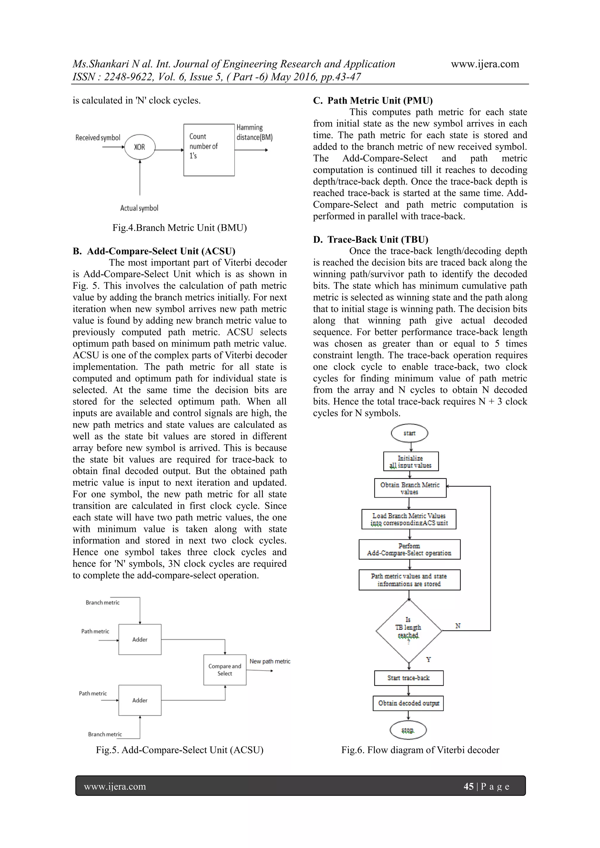
![Ms.Shankari N al. Int. Journal of Engineering Research and Application www.ijera.com ISSN : 2248-9622, Vol. 6, Issue 5, ( Part -6) May 2016, pp.43-47 www.ijera.com 46 | P a g e The flow of Viterbi decoder is represented in Fig.6. It involves initializing all inputs such as clock, reset, enable signals, actual codewords and received codewords. Proper operation of Viterbi decoder requires an active high reset signal, a single pulse of enable signal and a continuous clock signal. On initializing all input values branch metric and path metric values are calculated parallelly for each received symbol. The path information (state value and decision bit) are stored in a multi-dimensional array. Set trace-back length as greater than or equal to five times of constraint length. Once the number of symbols fed into Viterbi decoder reaches trace- back length, start trace-back and obtain decoded output. The total number of clock cycles required to obtain final output will be sum of number clock cycles required for branch metric calculation, add- compare-select operation and number of clock cycles required for trace-back. Hence 5N+N+3 = 6N+3 cycles required for N symbols. IV. PERFORMANCE ANALYSIS VHDL code for optimum design of Viterbi decoder is simulated using Modelsim 6.5b and synthesized using Xilinx 12.2. The simulation result is as shown in Fig. 6. 75 symbols are fed as input into Viterbi decoder. Trace-back length chosen was 36. Fig.6.Simulation result of Viterbi decoder From simulation result it is observed that the designed Viterbi decoder is able to correct single bit errors as well as two bit errors which are distributed randomly. Table 2: Resource utilization table Resources Utilization Number of unique control sets 94 Adder/Subtractors 35 Counters 3 Registers 39042 Comparators 65 Multiplexers 810 1 bit EX-OR 8 Table 3: Comparison of resource utilization between different FPGA devices Resources Utilization Spartan6 Spartan6 lower power Virtex4 Number of slice registers 6902 out of 184304(3%) 6862 out of 184304 (3%) 6859 out of 126800 (5%) Number of slice LUTs 5796 out of 92152(6%) 5794 out of 92152 (6%) 5794 out of 63400 (9%) Number of fully used LUT-FF pairs 1553 out of 11145 (13%) 1489 out of 11167 (13%) 1504 out of 11149 (13%) Number of bounded IOBs 7 out of 396(1%) 7 out of 396 (1%) 7 out of 210 (3%) Resources in different FPGA devices differ in numbers. The resource utilization details of designed Viterbi decoder obtained after synthesis which is compared between different FPGA devices. This comparison will help to select the best device to implement. The resource utilization of designed Viterbi decoder is shown in Table 2. V. CONCLUSION With the growing use of digital communication, there has been an increased interest in high speed Viterbi decoder design within a single chip. Hence by knowing the basic knowledge of convolutional coding and Viterbi decoding, basic structure of various blocks of Viterbi decoder is designed. The design is carried out for the convolutional encoder with code rate ½ and constraint length 7 which require 64 states, 4 parallel Branch Metric Units (BMUs) and 32 parallel Add- Compare-Select Units (ACSUs). The two ACSUs are combined in one module. The optimization in designed structure is required to obtain better design with low resource requirement, low power and high speed. The VHDL codes are generated in different code modules for each blocks of Viterbi decoder and then integrated. The designed Viterbi decoder is able to correct single as well as two bits errors. In general it corrects random errors. It is observed that number of resources required implementing Viterbi decoder on FPGA (Spartan 6, xc6slx150t,-3), by optimizing VHDL code are minimum compared to conventional Viterbi structure. REFERENCES [1]. A.J. Viterbi, Error Bounds for Convolutional Codes and Asymptotically Optimum Decoding Algorithm, Institute of Electrical and Electronics Engineers Transactions on Information Theory, IT-13, 1967, 260-269. [2]. Bernard Sklar, Digital Communications- Fundamentals and Applications (Second](https://image.slidesharecdn.com/i060506043047-160811043646/75/Hard-Decision-Viterbi-Decoder-Implementation-on-FPGA-and-Comparison-of-Resource-Utilization-on-Different-FPGA-Devices-4-2048.jpg)
![Ms.Shankari N al. Int. Journal of Engineering Research and Application www.ijera.com ISSN : 2248-9622, Vol. 6, Issue 5, ( Part -6) May 2016, pp.43-47 www.ijera.com 47 | P a g e Edition, Prentice Hall P T R, New Jersey, 381-435). [3]. G. D. Forney Jr., The Viterbi algorithm, Proceedings on Institute of Electrical and Electronics Engineers, 1973, 268-278. [4]. Yan Sun and Zhizhong Ding, FPGA Design and Implementation of Convolutional Encoder and a Viterbi Decoder Based on 802.11a for OFDM, Department of Communication Engineering, Hefei University of Technology, 2012, 125-131. [5]. Hui-Ling Lou, Implementation of the Viterbi Algorithm, Institute of Electrical and Electronic Engineers Acoustics, Speech, and Signal Processing Magazine , 1995, 26-41. [6]. Matthias Kamuf, Viktor Owall, and John B. Anderson,Optimization and Implementation of Viterbi Decoder under Flexibility Constraints, Institute of Electrical and Electronics Engineers Transactions on Circuits and Systems regular papers , 2008, 2411-2422. [7]. Gerhard Fettweis and Heinrich Meyr, High- Speed Parallel Viterbi Decoding: Algorithm and VLSI-Architecture, Institute of Electrical and Electrical and Electronics Engineers Communications Magazine , 1991, 46-55. [8]. [8] Marimuthu C.N, An efficient Viterbi Decoder Architecture, International organization of Scientific Research Journal of VLSI and Signal Processing , 2013,46-50.](https://image.slidesharecdn.com/i060506043047-160811043646/75/Hard-Decision-Viterbi-Decoder-Implementation-on-FPGA-and-Comparison-of-Resource-Utilization-on-Different-FPGA-Devices-5-2048.jpg)

This paper discusses the implementation of a hard decision Viterbi decoder on FPGA, emphasizing its importance in wireless communication systems for decoding convolutional codes. It details the architecture, including the branch metric unit, add-compare-select unit, and trace-back unit, while also comparing resource utilization across various FPGA devices. The findings demonstrate that the designed Viterbi decoder effectively corrects errors and optimizes resource requirements, making it suitable for high-speed applications.