A design pattern is a general solution to a commonly occurring problem in software design. It is a template to solve a problem that can be used in many different situations. Patterns formalize best practices that the programmer can use to solve common problems when designing an application or systems. In this article we have focused our attention on it, how the proposed UML diagrams can be implemented in C# language and whether it is possible to make the diagram implementation in the program code with the greatest possible precision.
![International Journal of Advanced Information Technology (IJAIT) Vol. 4, No. 6, December 2014 DOI : 10.5121/ijait.2014.4602 19 EXACT IMPLEMENTATION OF DESIGN PATTERNS IN C# LANGUAGE Viliam Malcher Faculty of Management, Department of Information Systems, Comenius University 820 05 Bratislava 25, Odbojárov 10, P.O. Box 95, Slovak Republic, Europe ABSTRACT A design pattern is a general solution to a commonly occurring problem in software design. It is a template to solve a problem that can be used in many different situations. Patterns formalize best practices that the programmer can use to solve common problems when designing an application or systems. In this article we have focused our attention on it, how the proposed UML diagrams can be implemented in C# language and whether it is possible to make the diagram implementation in the program code with the greatest possible precision. . KEYWORDS Design patterns, UML diagrams, C# language, Implementation of design patterns 1. INTRODUCTION Written program could be flexible, easily maintainable, and reusable, it means might be elegant. How we know that a program is elegant as it can be? The answer is that a successful programmer has two primary tools − a good programming language and design patterns. Design patterns represent some templates to create a program that we can use for some group of similar tasks. For example, let us consider a picture. We want to add borders and captions to the picture. Or let us to consider a user and an admin (administrator) type of rights. What do these things have in common? At a first view it seems that nothing. However, with picture frame and labels, the picture can be seen as that, which is "decorated" with frames and labels. Similarly, admin rights can be seen as the user rights, and some rights more. So, the admin rights we do not have to program from the basic state, it is enough to create admin rights by specifying of the user – admin rights will be a decoration of user rights. For these types of tasks is proposed a model called the Decorator [1]. In this paper we discuss how for proposed UML diagrams [2-4] of design patterns can be implemented programs in C# language exactly as it could be. For some patterns were set up differently the UML diagrams [5] if we compare it with the GoF [1]. For the pattern represented by the UML diagram does not exist sufficiently accurate software implementation, so that we can meet with different implementations of the patterns sometimes. This can reduce their understanding. Our aim is to show how this can be improved.](https://image.slidesharecdn.com/4614ijait02-250319114815-b4e9a1f4/75/EXACT-IMPLEMENTATION-OF-DESIGN-PATTERNS-IN-C-LANGUAGE-1-2048.jpg)
![International Journal of Advanced Information Technology (IJAIT) Vol. 4, No. 6, December 2014 20 2. DESIGN PATTERNS AND UML DIAGRAMS In the original work of the GoF group [1] were introduced the 23 design patterns, which are considered as basic patterns. Every design pattern has a corresponding UML diagram. However, even for same patterns were established different UML diagrams [5]. Then we have two problems. The first problem is to determine the UML diagram for the pattern. Most programs are based on the proposal, which did GoF. The second problem is how make sufficiently accurately software implementation of the UML diagrams for the design patterns. Take as an example the Decorator pattern. The GoF have proposed for this pattern following diagram [1]: Figure 1. The UML diagram proposed by the GoF group [1] In the book [1] was given a fragment of code in C++ language, how it could be programmatically implemented the UML diagram shown in Figure 1. J. Bishop has proposed a slightly modified the UML diagram for the implementation of the Decorator [5] shown in Figure 2 Fig. 2. The UML diagram for Decorator proposed in the book [5]](https://image.slidesharecdn.com/4614ijait02-250319114815-b4e9a1f4/75/EXACT-IMPLEMENTATION-OF-DESIGN-PATTERNS-IN-C-LANGUAGE-2-2048.jpg)
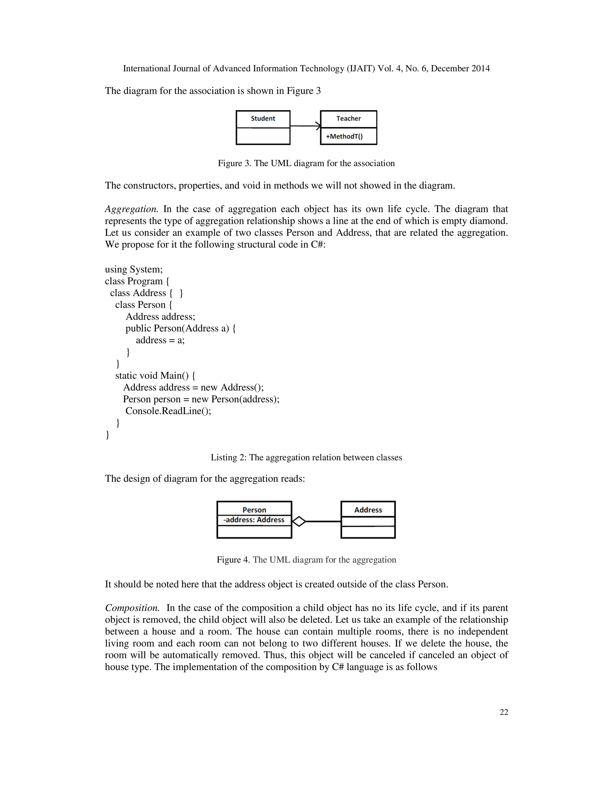
![International Journal of Advanced Information Technology (IJAIT) Vol. 4, No. 6, December 2014 21 It also were implemented the program code in C# language based on the diagram (Figure 2). Some parts of the code are problematic in terms of the exact implementation. In the book [5] it had not been established software implementing of association, aggregation, composition, and other relations between the classes. Our task is therefore to implement software for the basic relationships between two classes in C# and based on them to create a C# code of design patterns. We do it for the Decorator pattern as an example. The UML diagrams are not often an exact copy of the program. In the diagram are shown important elements. Accessibility of all attributes and operations are appropriately marked (private (-), protected (#), public (+)), attributes are usually private and methods are public. Types associated with the operations are usually not mentioned. If however the types are important, they can be inserted after the colon. The same procedure is applied for parameters of the methods. Designing an application using object-oriented programming provides inheritance, polymorphism, encapsulation, etc. Apart from these concepts, it is very important to understand some logical concepts along with technical concepts. In this article, we will be discussing some of the concepts, which we use in most of the classes. Association. Association is defined as a structural relationship, which conceptually means that the two classes are linked to each other. In this relationship one class instance uses the other class instance or vice-versa, or both may be using each other. But the main point is, that the lifetime of the instances of two classes are independent of each other and there is no ownership between two classes. Consider an example of Student-Teacher relationship. Conceptually speaking, each student can be associated to multiple teachers and each teacher can associate to multiple students. We have two classes Student and Teacher having the association relationship. Both classes are on an equal level, there is no ownership. This means that it is not possible to create an object instance of the class in the second class. On the other hand, the Student class can call the methods, which are present in the class Teacher, this reflects the direction of the arrow in the diagram. The class Teacher will not call the method created in the Student class. We make an implementation of this relationship in C# language as follows: using System; class Program { class Teacher { public void MethodT() { } } class Student { public Student(Teacher t) { t.MethodT(); } } static void Main() { Teacher t = new Teacher(); Student s = new Student(t); Console.ReadLine(); } } Listing 1: The association relation between classes](https://image.slidesharecdn.com/4614ijait02-250319114815-b4e9a1f4/75/EXACT-IMPLEMENTATION-OF-DESIGN-PATTERNS-IN-C-LANGUAGE-3-2048.jpg)
![International Journal of Advanced Information Technology (IJAIT) Vol. 4, No. 6, December 2014 25 using System; class Program { interface IComponent { string Operation(); } class Component : IComponent { public string Operation() { return "I am walking"; } } class Decorator : IComponent { IComponent component; public Decorator(IComponent c) { component = c; } public string Operation() { string s = component.Operation(); s += " and listening my music"; return s; } public string AddedBehavior() { } } static void Main() { IComponent component = new Component(); IComponent c = new Decorator(component); Console.WriteLine(c.Operation()); Console.ReadLine(); } } Listing 5: The Decorator pattern 3. CONCLUSIONS We have shown that if we define the programs for the basic relationships between two classes, it is possible to achieve more accurate software implementations of the UML diagram. We can also create diagrams for the designed software, which allow us to keep the software in a graphic form in the documents. Really, we can more exactly make the program implementation from designed the UML diagrams [6,7], and after further filled some elements in the diagrams this state could be still improved. REFERENCES [1] E. Gamma., R. Helm, R. Johnson, and J. O. Vlissides, Design Patterns: Elements of Reusable Object- Oriented Software, M. A. Addison-Wesley, Boston, 1995. [2] J. Rumbaugh, I. Jacobson, G. Booch, The Unified Modeling Language Reference Manual, Addison- Wesley Longman, Inc., 1999. [3] M. Fowler, UML destilled, 3th ed., Addison-Wesley, Pearson Education, Inc., 2004. [4] J. Arlow, and I. Neustadt, UML and the Unified Process, Pearson Education Limited, 2002. [5] J. Bishop, C# 3.0 Design Patterns, O’Reilly Media, Inc., 2007. [6] Ch. G. Lasater, Design Patterns, Wordware Publishing, Inc., 2007. [7] McC. J. Smith, Elemental Design Patterns, Person Education, Inc., 2012.](https://image.slidesharecdn.com/4614ijait02-250319114815-b4e9a1f4/75/EXACT-IMPLEMENTATION-OF-DESIGN-PATTERNS-IN-C-LANGUAGE-7-2048.jpg)