Download to read offline
![International Research Journal of Engineering and Technology (IRJET) e-ISSN: 2395-0056 Volume: 10 Issue: 05 | May 2023 www.irjet.net p-ISSN: 2395-0072 © 2023, IRJET | Impact Factor value: 8.226 | ISO 9001:2008 Certified Journal | Page 1762 Design and Implementation of JPEG CODEC using NoC MADIHA KAUSAR1, MOHAMMED ARSHAD MURTAZA2, KAUSER ANJUM3 1Assistant Professor, Dept. of E&CE, K.C.T. Engineeering College, Kalaburagi, Karnataka, India 2M.Tech Student, VLSI & Embedded Systems, Sharnbasva University, Kalaburagi, Karnataka, India 3 Ph.D, Dept. of E&CE, K.C.T. Engineeering College, Kalaburagi, Karnataka, India ---------------------------------------------------------------------***--------------------------------------------------------------------- Abstract - An image compression and decompression system using NoC structure is developed and implemented. Due to the increasing demands of image transmission in computer and mobile systems, research on image compression has increased significantly. The JPEG (Joint Photographic Experts Group) standard is a commonly used method for lossless compression of digital images, especially those produced by digital photography. Digital images require a lot of storage space. The aim of this work is to design a VLSI architecture for basic sequential JPEG encoding and decoding processes. A codec that specifies how an image is compressed into a stream of bytes and then decompressed back into an image is defined by the JPEG standard. To achieve high execution speed, the architecture makes best use of pipeline and parallelism principles. Providing effective on-chip communication networks, network-on-chip (NoC) is a new paradigm in complicated system-on-chip (SoC) designs. It enables scalable communication and decoupling of communication and computing. Data is sent over networks as packets. Data routing is primarily done through routers. The router architecture must therefore be effective, with lower latency and higher throughput; the effectiveness of the router architecture is assessed in a two-dimensional network topology. NoC is used to speed up the image transfer process and thus provide a shorter processing time for transferring data over the network. The design is implemented using Verilog HDL and simulated in Xilinx ISE Design Suite 14.7. Key Words: Image processing, Lossy Image compression, Image decompression, JPEG, CODEC, NoC. 1. INTRODUCTION The reason why digital representation of the signal is more reliable than its analogue counterpart for processing, manipulation, storage, recovery, and transmission over long distances, even across the globe through communication networks, is why we are talking about digital networks, digital representation of images, movies, video, TV, voice, and digital libraries today. Digital technology has only recently been used to the transmission, recording, and processing of images, but it has quickly revolutionised many areas of image processing. Because it can carry out operations that are challenging or impossible to carry out in the usual analogue format, the digital mode has largely supplanted analogue technology in various applications. So, both when they are created and when they are presented, video signals are intrinsically analogue. There is an opportunity to transform these signals into digital format in between these end points. For effective storage and transmission, digital images must be compressed because they have a significant amount of data. The need for digital picture storage, editing, and transport has exploded with the advent of digital cameras. These image files have a tendency to be enormous and take up a lot of RAM. A typical 640 x 480 color image has about a million elements, but a 256 x 256 grayscale image has 65,536 to store. Standard broadcast television requires 100 to 200 Mbps for video applications, whereas low resolution applications like teleconferencing, remote surveillance, etc. just need a few megabits per second, when the frame rate and word size are decreased, the data rate can be brought down to a few tens of kilobits. Using picture compression methods at the source could result in even more compression. At the destination, these compressed images are decompressed for viewing and analysis. Many picture compression methods have been developed in the recent years. These methods seek to reduce the size of the photos by sending just the non-redundant data as it is received. Other methods are inherently lossy. In this case, the reconstructed images are actually close copies of the uncompressed originals. The original and reconstructed images' corresponding pixel values are different. As a result, compression may be accomplished without significantly affecting the visual image quality. A group of picture compression mechanisms are defined by the JPEG standard. The baseline sequential encoding scheme is the mechanism that is most frequently utilised. This approach for lossy compression [1] is used. Image compression and decompression techniques can be used to solve the digital picture transmission issue. In order to speed up the forwarding of images and provide a shorter processing time to transfer data through the network with a low latency, it can only transmit non- redundant data, as it does with NoC. Providing effective on-chip communication networks, a network-on-chip](https://image.slidesharecdn.com/irjet-v10i5322-230701103818-842521af/75/Design-and-Implementation-of-JPEG-CODEC-using-NoC-1-2048.jpg)
![International Research Journal of Engineering and Technology (IRJET) e-ISSN: 2395-0056 Volume: 10 Issue: 05 | May 2023 www.irjet.net p-ISSN: 2395-0072 © 2023, IRJET | Impact Factor value: 8.226 | ISO 9001:2008 Certified Journal | Page 1763 (NoC) is a new paradigm in complicated system-on-chip (SoC) designs [2]. Scalable communication is possible, and communication and processing can be separated. 2. NETWORK ON CHIP (NoC) The NoC technology was created to address bus short circuits. It is a method for creating a SoC design's inter- core communication subsystem for intellectual property. Dedicated buses are used between communication resources in the system-on-chip communication strategy. It does not allow for any flexibility when it comes to communication requirements, thus planning is always a need. Using public transportation is still an option, but it has the drawback of not scaling up properly as the number of resources increases. By putting in place a network of switches, micro-routers, and resources for communication, NoC is intended to address these flaws. Future ASIC design has been suggested using the NoC design paradigm. The move to NoC-based solutions is being fuelled primarily by the present VLSI chip communication design methodology's inability for deep sub-micron chip fabrication technology. Technology scaling's detrimental effects on global connections, a higher reliance on fault mechanisms as feature 6 size reduces, and a growth in the use of parallel architectures are some of the factors contributing to NoC's rising popularity. The manufacture of such integrated chips presents a number of design issues for NoC-based system-on-chips. First, a target NoC topology that complies with the design limitations and performance specifications. Second, the physical connection mechanisms for data transfer between processor cores are provided by the design of network interfaces to access the on-chip network and routers. The third consideration is selecting communication protocols appropriate for chips interconnect networks. Finally, the network of chips for the future will grow increasingly sensitive and prone to mistakes and failures as the magnitude and speed of technological progress rise. When communicating via chips, fault tolerance becomes crucial. For reduced wire routing, easier timing shutdown, higher running frequencies, and quick IP address changes, today's SoCs need on-chip network IP connectivity. System-on-chip success for next embedded applications depends on network-on-chips technology. 2.1 NoC ARCHITECTURE The general architecture of the NoC is depicted in Figure 1. Processor Elements (PE), Network Interfaces (NI), Routers (R), and Channels make up this system. Each PE has a network interface that connects it to a nearby router (NI). WE establish a logical connection between the network and the IP core. The front end and the back end can be separated into two components. The UI handles requests to the IP core and is not aware of the network. The back end, which manages network protocol, sorts and arranges packets, buffers, and aids the router with storage, is directly connected to the network. Data packets are transmitted between the source PE and the destination PE. During transmission, the packet is transmitted over the network hop by hop in accordance with the router's choice. Switches and a buffer are also components of a router. Here, store and forward buffering is applied. A router and a related link make up a node. Links allow for data transmission on the network by transferring packets between routers. According to the chosen topology, it consists of a number of wires connecting various router networks; in this case, a 33 2D-Mesh NoC structure is employed. A router is in charge of transferring data utilising particular routing algorithms and control flow mechanisms from source to destination. Fig- 1: General Architecture of NoC 3. PROPOSED METHOD Figure 2 displays a block diagram of a JPEG codec with NoC. There are various processes involved in the encoding process.](https://image.slidesharecdn.com/irjet-v10i5322-230701103818-842521af/75/Design-and-Implementation-of-JPEG-CODEC-using-NoC-2-2048.jpg)
![International Research Journal of Engineering and Technology (IRJET) e-ISSN: 2395-0056 Volume: 10 Issue: 05 | May 2023 www.irjet.net p-ISSN: 2395-0072 © 2023, IRJET | Impact Factor value: 8.226 | ISO 9001:2008 Certified Journal | Page 1764 Fig- 2: Block diagram of the JPEG Codec with NoC 3.1 Encoding 1. Conversion of the image's color space: The image should first be transformed from RGB to Y′CBCR (or informally YCbCr). There are three parts to it: Y', CB, and CR. Y' represents the brightness of the pixel, while CB and CR represent the colour (divided into blue and red components). The colour space utilised in digital colour television and digital video, including DVD video, is roughly the same. Higher compression is possible thanks to the Y′CBCR colour space conversion without considerably lowering the observed image quality. 2. Downsampling: People perceive image detail in image brightness (Y' component) substantially more clearly than in image hue and saturation due to the density of colour and light sensitive receptors in the human eye (Cb and Cr components). Encoders can be made to compress images more effectively using this information. Reducing the spatial resolution of the Cb and Cr components is a common next step when converting to the Y′CBCR colour model (referred to as "downsampling" or "color subsampling"). JPEG images are often downscaled at ratios of 4:4:4 (no down-processing), 4:2:2 (by a factor of 2 horizontally), or (most frequently) 4:2:0 (by a factor of 2 both horizontally and vertically). The remaining press treats Y', Cb, and Cr differently but quite similarly. 3. Block division: Each channel must be divided into 88 blocks after subsampling. This results in minimum coded units (MCU) blocks of size 8 8 (4:4:4 - no subsampling), 16 8 (4:2:2), or most frequently 16 16, depending on the colour subsampling (4:2:0). Macroblocks are what MCUs are known as in video compression. If the channel data does not represent an integer number of blocks, the encoder must insert some sort of dummy data into the remaining empty block region. Filling edges with a solid colour (like black) may result in ringing artefacts in the border's visible portion. Such artefacts can be reduced (but not always entirely eliminated) via edge pixel rendering, and more advanced edge-filling techniques can also be applied. Fig- 3: 8x8 sub-image in grayscale with 8 bits 4. Discrete Cosine Transform (DCT): Next, a normalised two-dimensional Type II Discrete Cosine Transform is used to transform each 8 8 block of each component (Y, Cb, Cr) into a frequency domain representation (DCT). One such 88 8-bit subimage might be, for instance: An 8 x 8 block's values are shifted from the positive range to zero-centered before the DCT is calculated. Each starting block entry for an 8-bit picture falls between the [0, 255] range. The amended range is [-128, 127], and it is obtained by subtracting the midpoint of the range (in this case, the value 128) from each input. The subsequent level of DCT processing will require less dynamic range thanks to this step. These values are obtained as a result of this step:](https://image.slidesharecdn.com/irjet-v10i5322-230701103818-842521af/75/Design-and-Implementation-of-JPEG-CODEC-using-NoC-3-2048.jpg)
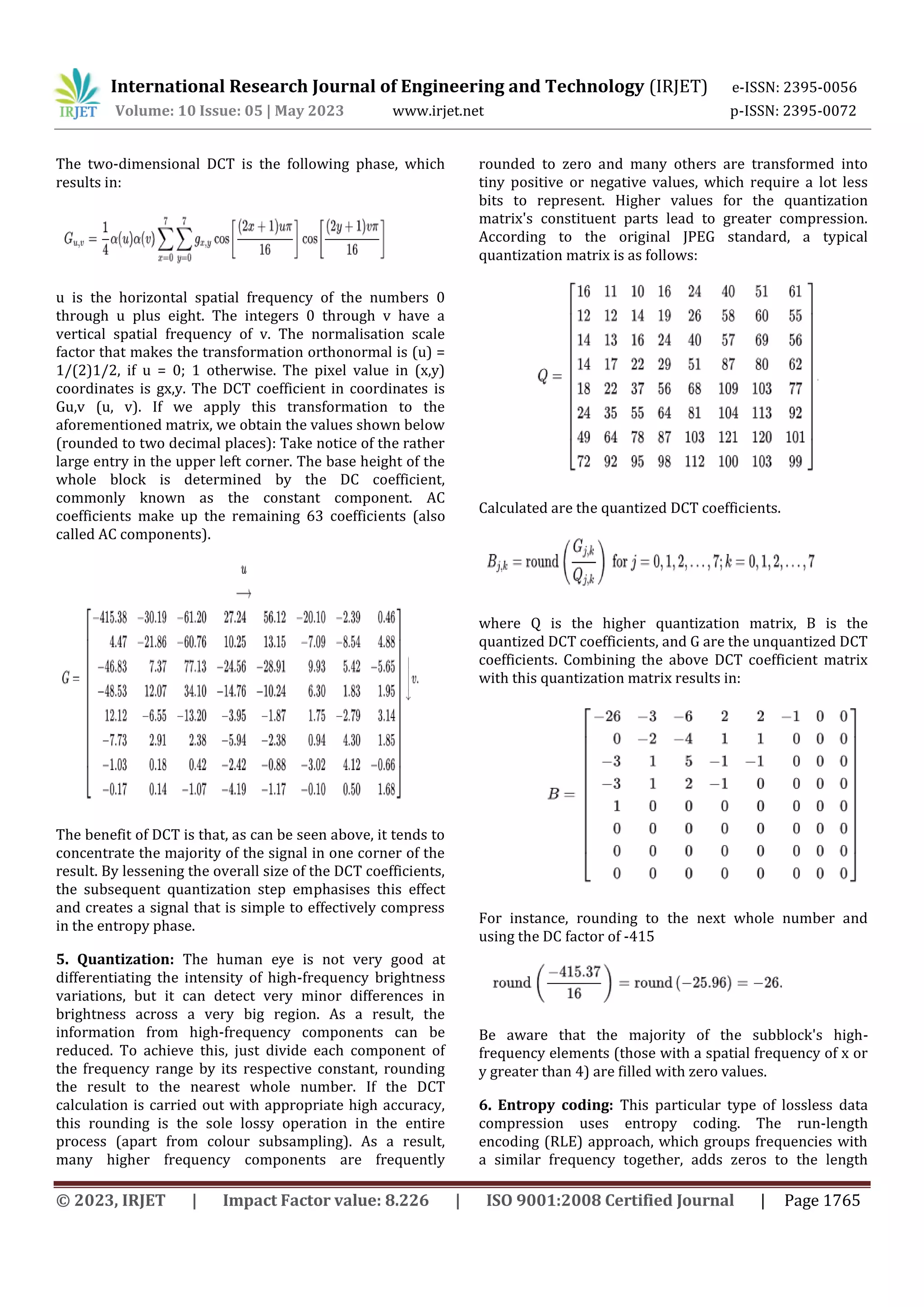
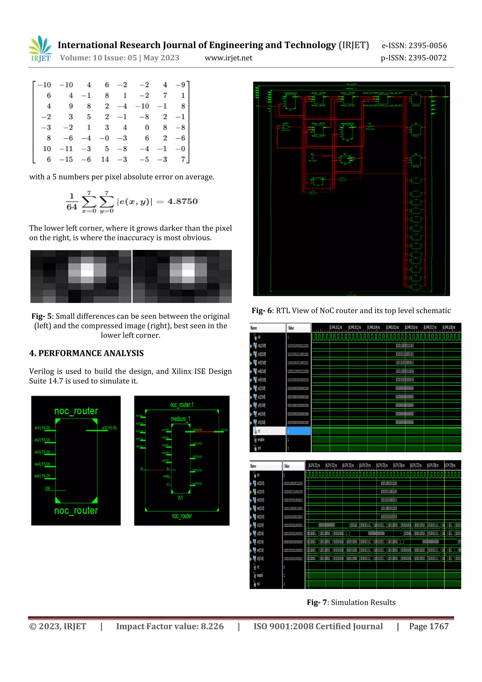
![International Research Journal of Engineering and Technology (IRJET) e-ISSN: 2395-0056 Volume: 10 Issue: 05 | May 2023 www.irjet.net p-ISSN: 2395-0072 © 2023, IRJET | Impact Factor value: 8.226 | ISO 9001:2008 Certified Journal | Page 1766 encoding, and then applies Huffman encoding to the remaining bits, is used to arrange the image components in a "zigzag" pattern. Fig- 4: Zigzag arrangement of JPEG image components 3.2 NoC Router The NoC takes compressed image data as input, its function is to speed up the image transfer process and thus provide shorter processing time for low-latency data movement in the network. 3.3 Decoding There are various steps involved in decoding: All of the aforementioned stages are performed in reverse to display the image during decoding. Consider the DCT coefficient matrix (after adding the DC coefficient difference) then using the quantization matrix and the input from the aforementioned result This closely resembles the upper-left corner of the original DCT coefficient matrix. The two-dimensional inverse DCT (2D Type III DCT), which is the following step, is obtained by: where x is an array of integers from 0 to 8. The integers 0 through 8 make up the pixel column y. For numbers 0 through u and up to 8, (u) is defined as above. In coordinates, Fu,v reconstructed the approximation coefficient (u, v). The value of the reconstructed pixel in (x, y) coordinates is fx,y. As the original contained integers, rounding the result to integers yields the numbers in the illustration (delimited by 128) then multiplying each entry by 128 Here you may view the decompressed subimage. Generally speaking, the decompression process may produce values outside of the initial input range of [0, 255]. In this situation, the decoder must trim the output values to keep them within this range in order to prevent overflow while maintaining the decoded image's original bit depth. By subtracting the original from the uncompressed picture, the original subimage and the decompressed subimage can be contrasted (see also the images on the right), resulting in the incorrect set of values shown below:](https://image.slidesharecdn.com/irjet-v10i5322-230701103818-842521af/75/Design-and-Implementation-of-JPEG-CODEC-using-NoC-5-2048.jpg)
![International Research Journal of Engineering and Technology (IRJET) e-ISSN: 2395-0056 Volume: 10 Issue: 05 | May 2023 www.irjet.net p-ISSN: 2395-0072 © 2023, IRJET | Impact Factor value: 8.226 | ISO 9001:2008 Certified Journal | Page 1768 Fig- 8: RTL View of JPEG CODEC and its top level schematic Fig- 9: Simulation Result 5. CONCLUSIONS The design and implementation of an image compression and decompression system utilising the NoC structure in Verilog HDL was effective. Thus, it provides faster data transmission through the network and is used to quicken the forwarding of images. Future development will involve expanding router architectures and building a productive NoC. The NoC's FPGA version will also be done. On comparing with other different compression techniques, came to a conclusion that JPEG image compression and decompression algorithm is an efficient technique for to some extent. REFERENCES [1] Udaya Kumar H, Madhu B C, “Design and Implementation of Lossless Data Compression Coprocessor using FPGA” International Journal of Engineering Research & Technology (IJERT) ISSN: 2278- 0181 IJERTV4IS05083 Vol. 4 Issue 05, May-2015. [2] Muhammad Athar Javed Sethi, Fawnizu Azmadi Hussin, Nor Hisham Hamid, “ Survey of Network On Chip Architectures” Department of Electrical & Electronic Engineering, Universiti Teknologi PETRONAS, Tronoh, Perak, Malaysia, Sci.Int.(Lahore),27(5),4133-4144,2015. [3] Moh’dAli Moustafa Alsayyh , Prof. Dr. Dzulkifli Mohamad &. Waheeb abu-ulbaa, “Image Compression Using Discrete Cosine Transform and Discrete Wavelet Transform” Journal of Information Engineering and Applications ISSN 2224-5782 (print) ISSN 2225-0506 (online) Vol.3, No.11, 2013. [4] S. Deb, et al., “CMOS Compatible Many-Core NoC Architectures with Multi-Channel Millimeter-Wave Wireless Links”, Proceedings of Great Lakes Symposium on VLSI (GLSVLSI), 3rd -4th May 2012. [5] M. Bechtel Brabi and Dr. A. Rajalingam., ” Recent survey for Bi-Directional network on chip pipelined architecture” International journal of Advanced Research in computer science and Software Engineering, Volume-2, issue-12, December 2012.](https://image.slidesharecdn.com/irjet-v10i5322-230701103818-842521af/75/Design-and-Implementation-of-JPEG-CODEC-using-NoC-7-2048.jpg)

This document describes the design and implementation of a JPEG codec using a Network-on-Chip (NoC) structure. It aims to speed up the image transfer process and provide shorter processing times. The key steps are: 1. The JPEG encoding process includes color space conversion, downsampling, block division, discrete cosine transform, quantization, and entropy coding to compress the image. 2. A NoC is used to transmit the compressed image data packets across the chip to reduce latency during transfer. 3. The JPEG decoding process reverses the encoding steps through entropy decoding, dequantization, inverse discrete cosine transform, and image reconstruction to decompress the image for viewing.