Downloaded 437 times


The Control Loop Foundation short course provides an overview of critical concepts and techniques in process control, covering both batch and continuous processes. It includes insights on measurement, control strategies, process dynamics, and practical applications in various domains like DCS and fieldbus systems. Additionally, the course emphasizes hands-on workshops for engineers aiming to enhance their understanding and implementation of control systems.
Introduction of Control Loop Foundation course led by Terry Blevins and Mark Nixon, focusing on batch and continuous processes.
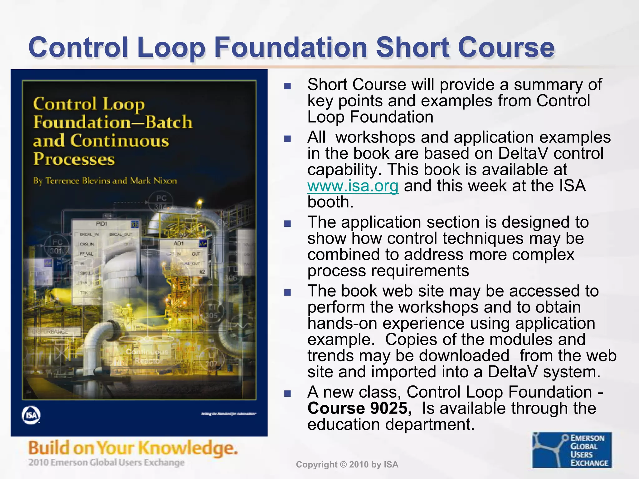
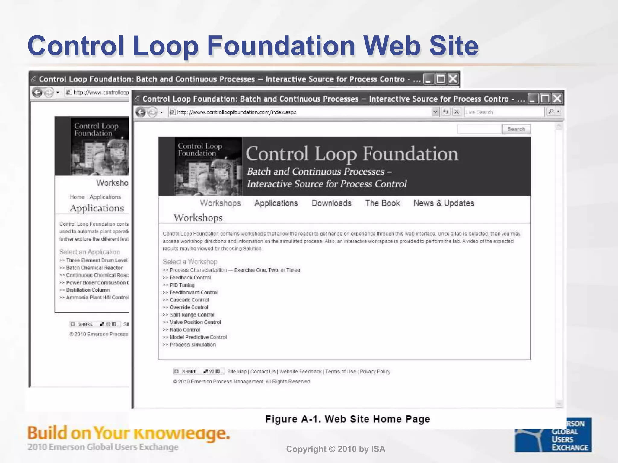
Details on the Control Loop Foundation Short Course, covering key points, workshops, and access to materials.
Basics of process control, offering terminology and concepts applicable across different systems.
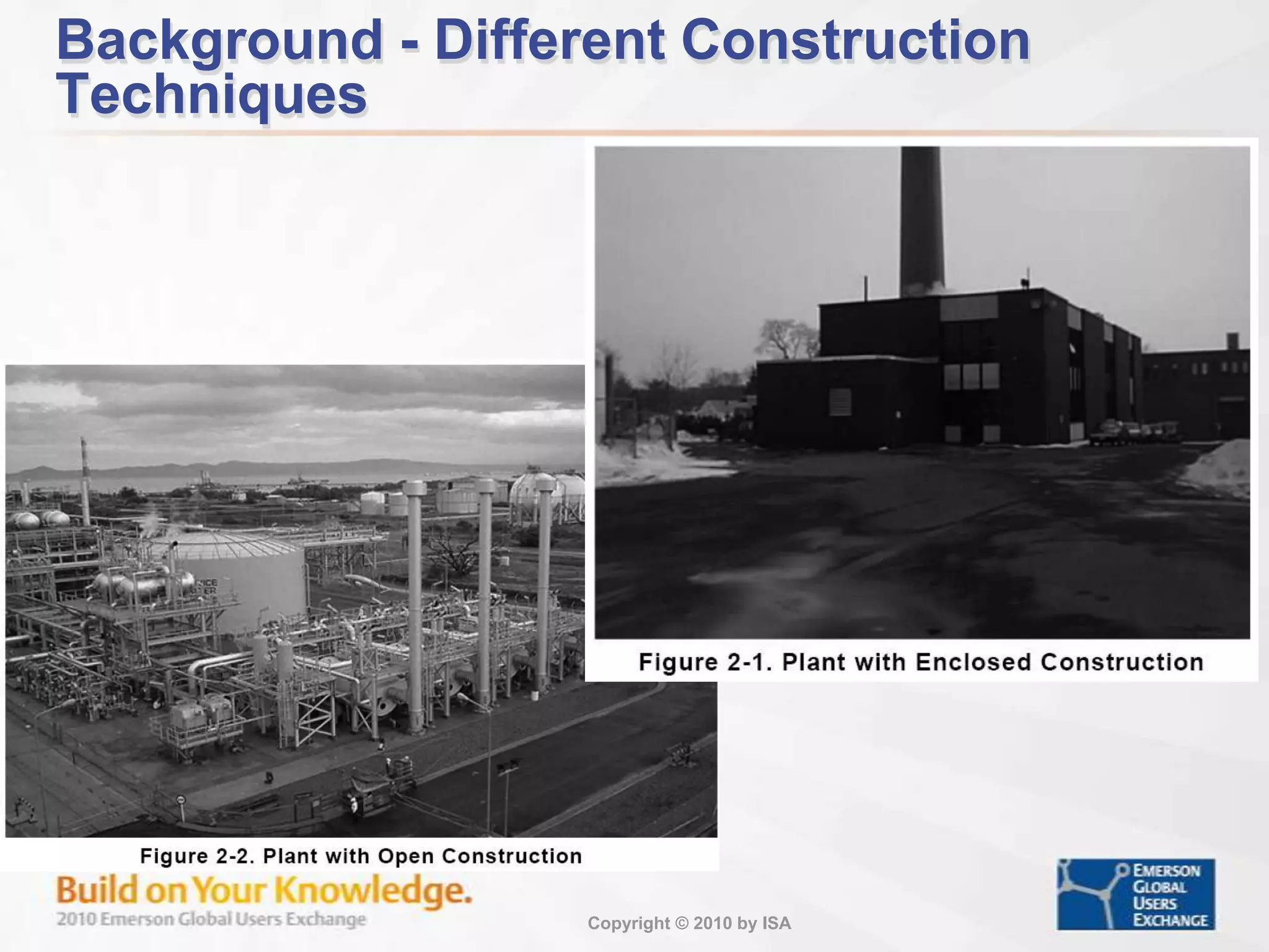
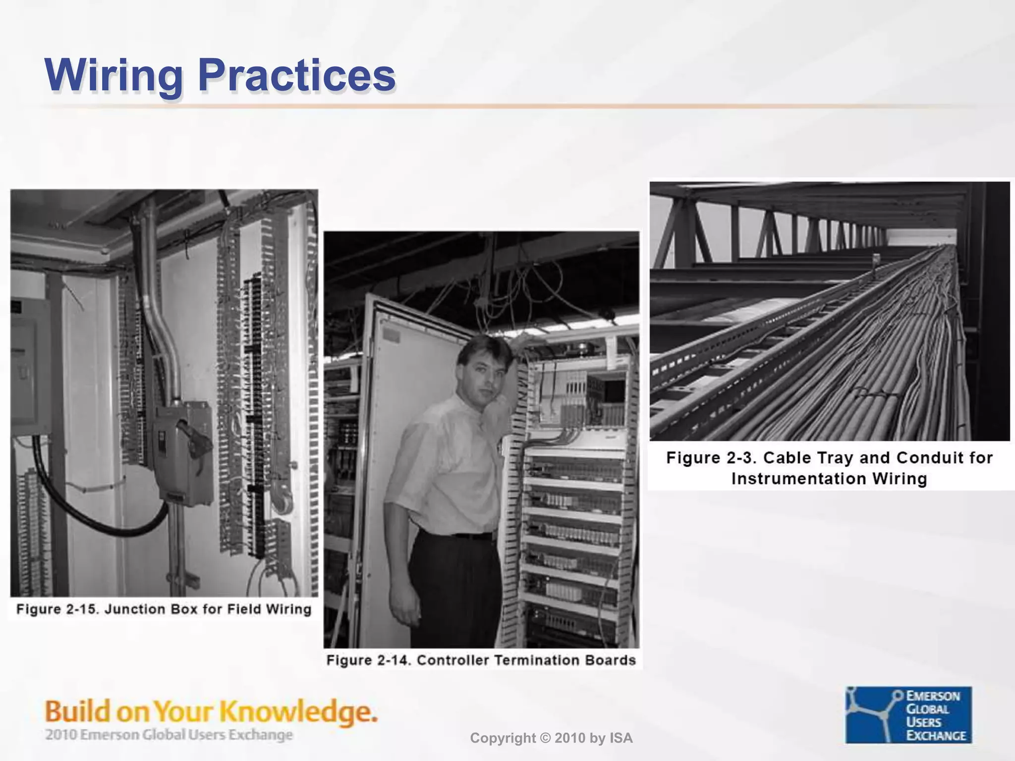
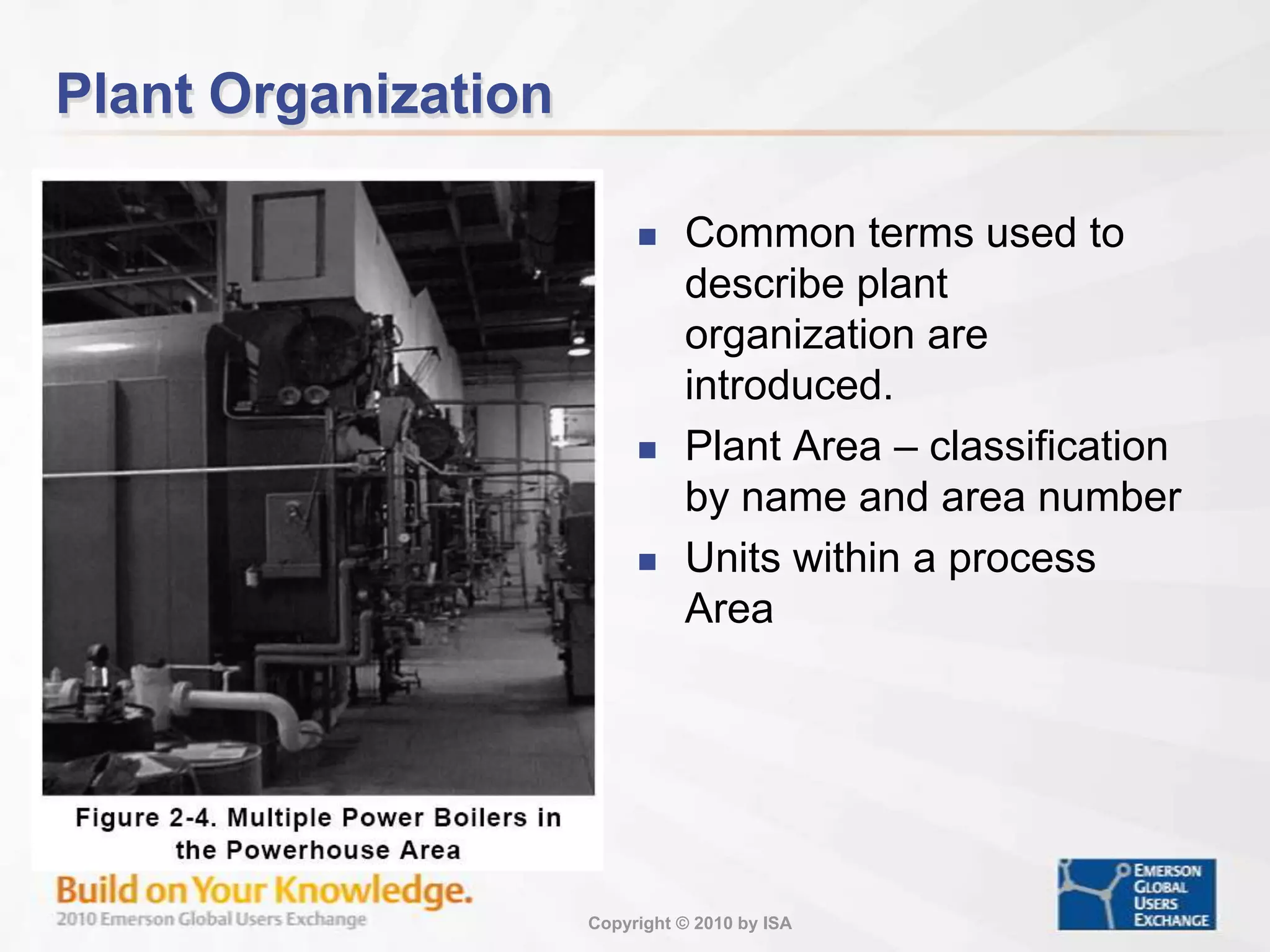
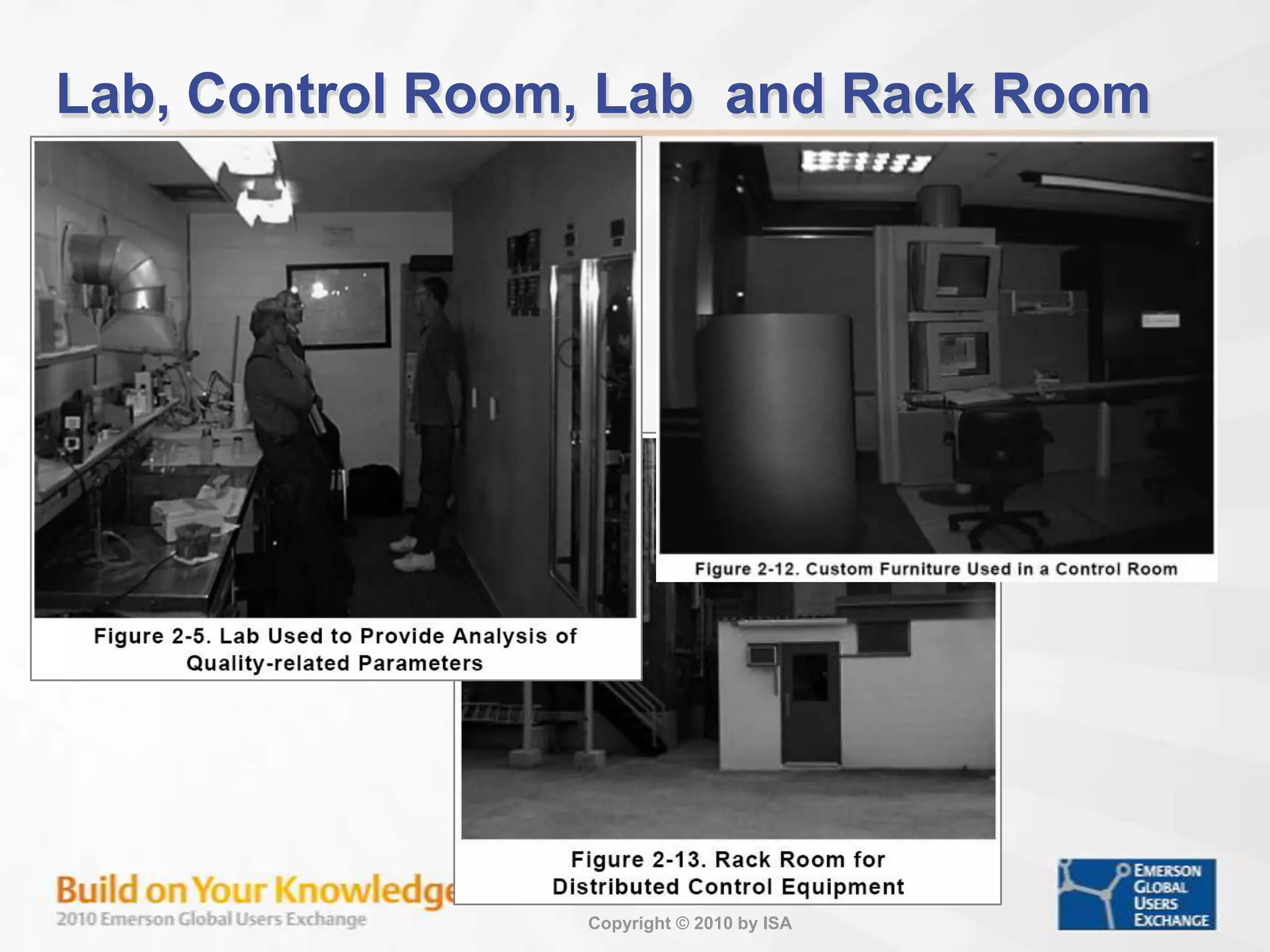
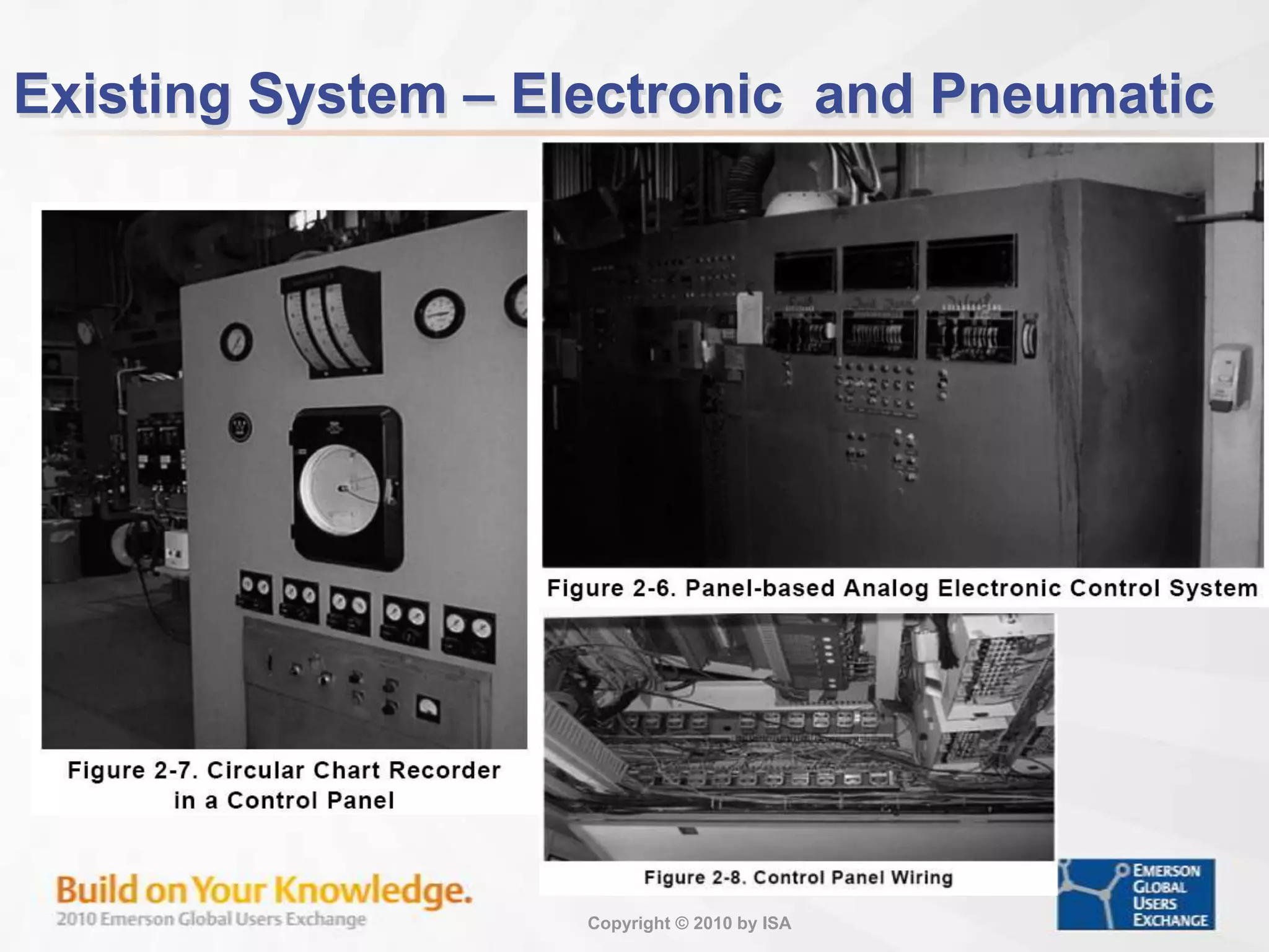
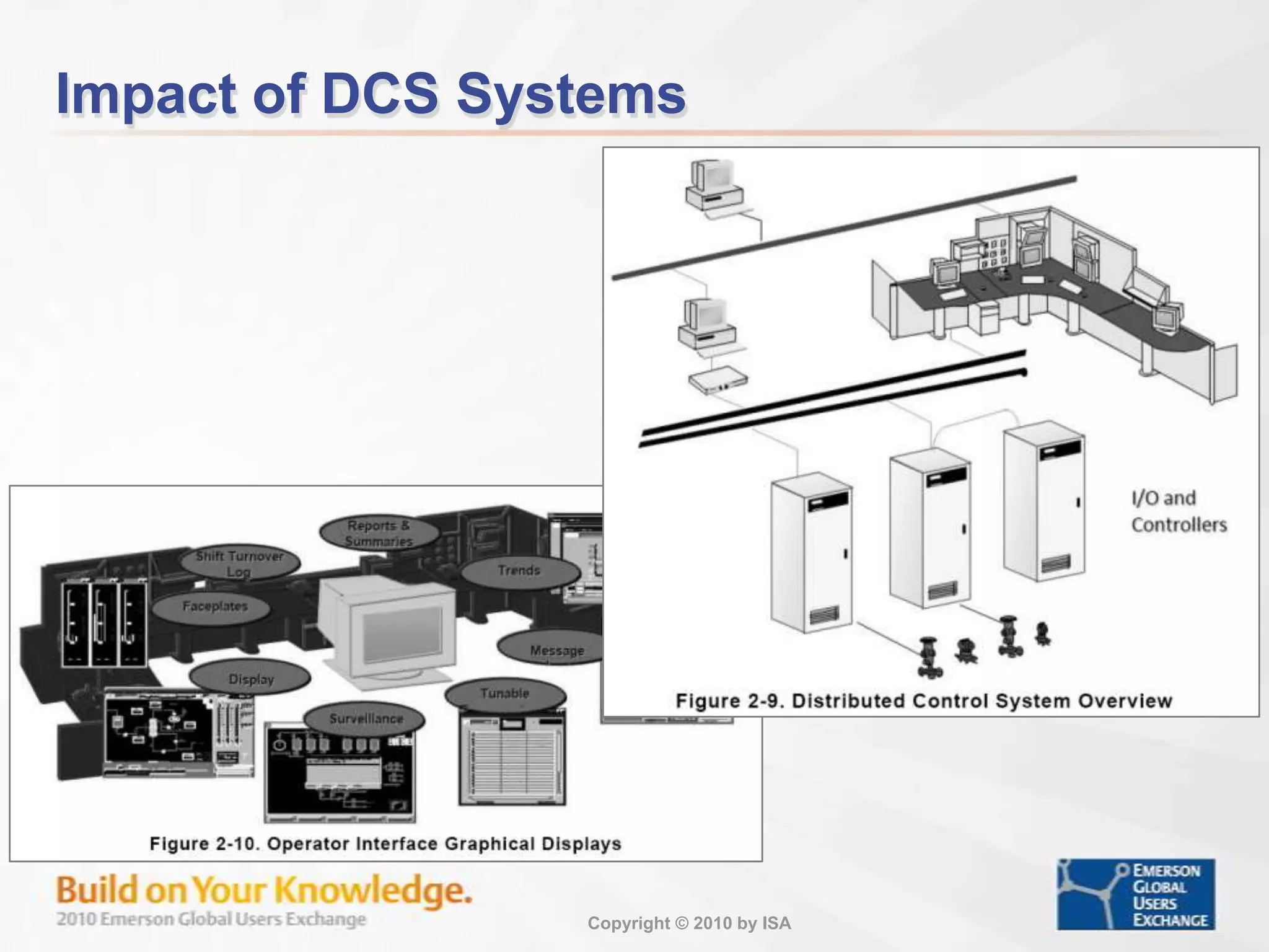
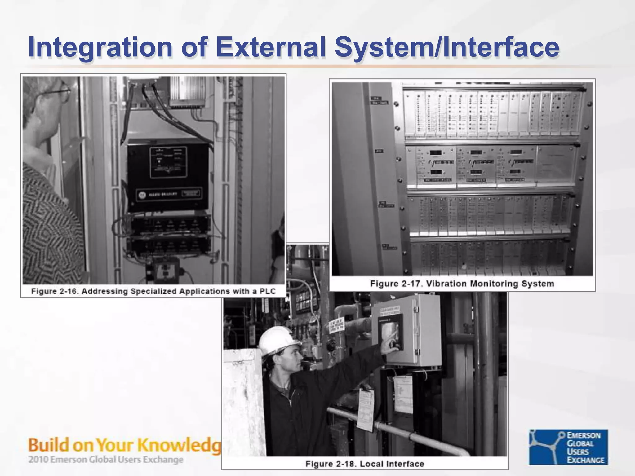
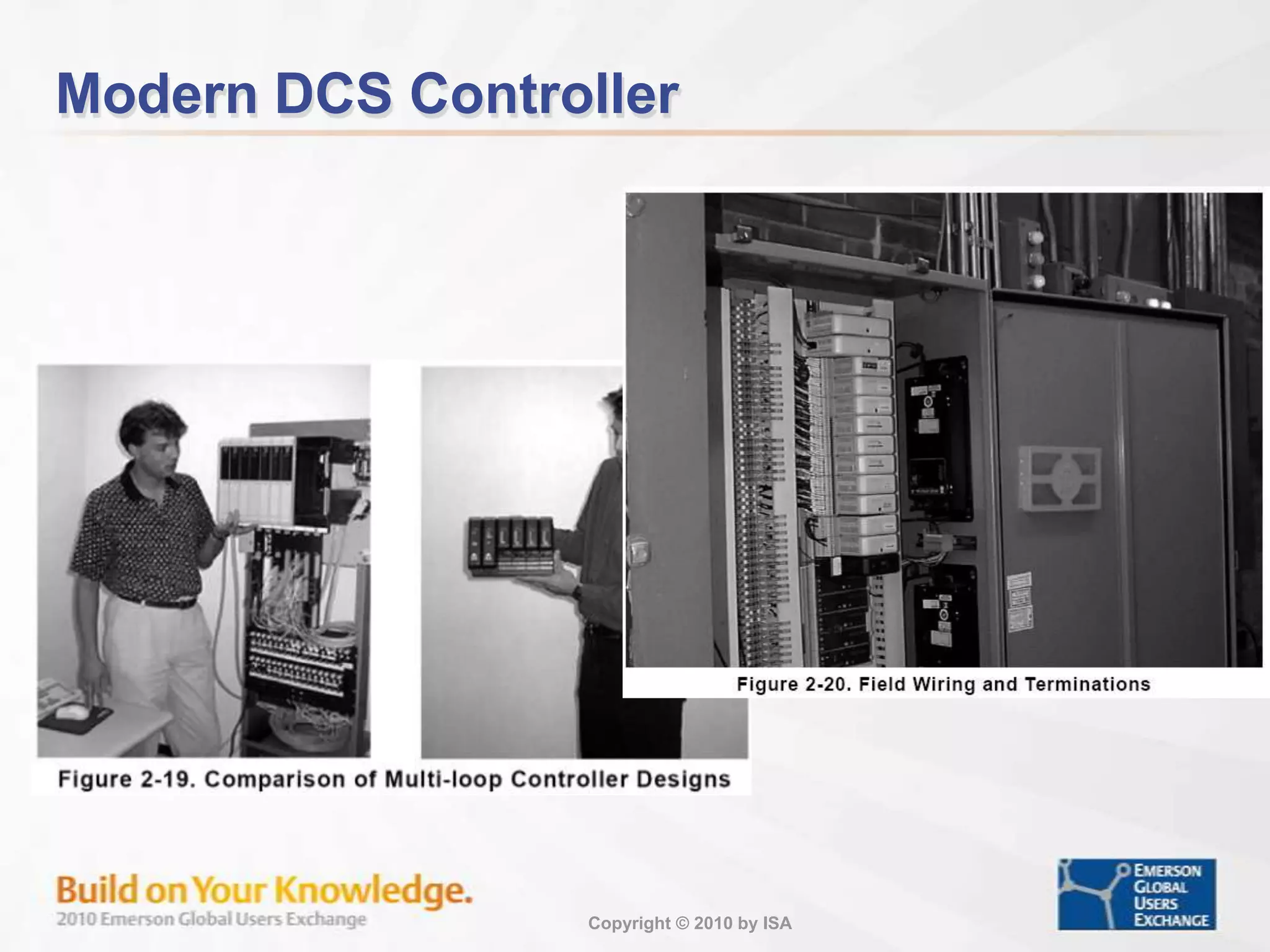
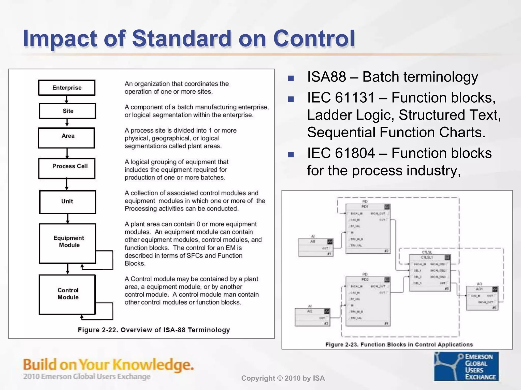
Overview of wiring practices, plant organization, and the roles of DCS systems in control.
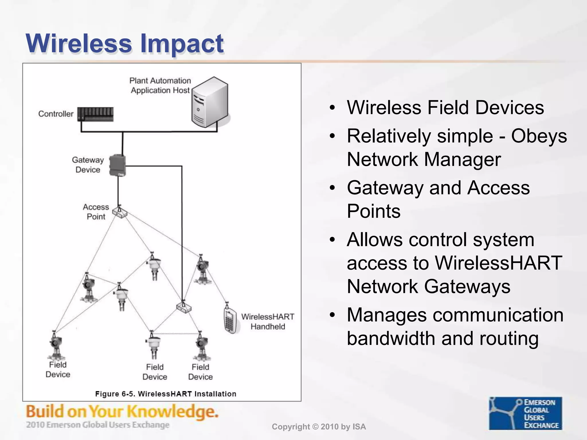
Exploration of digital communication technologies like Ethernet and WirelessHART in process control.
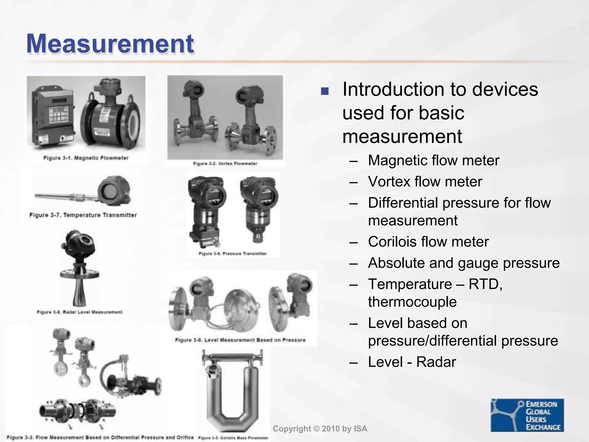
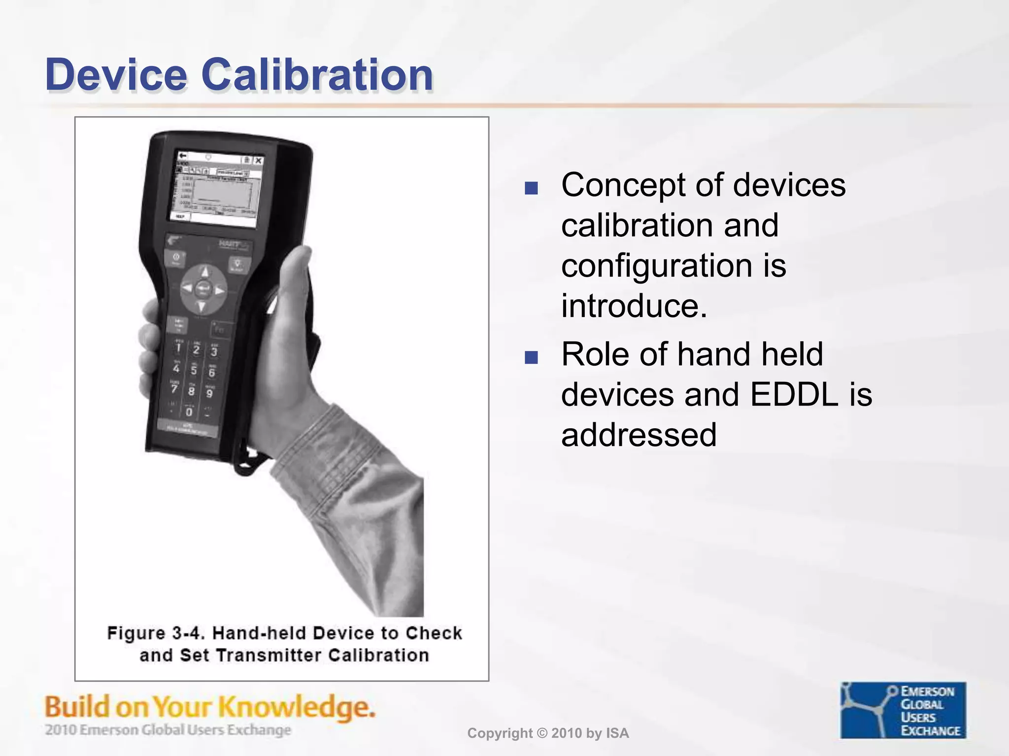
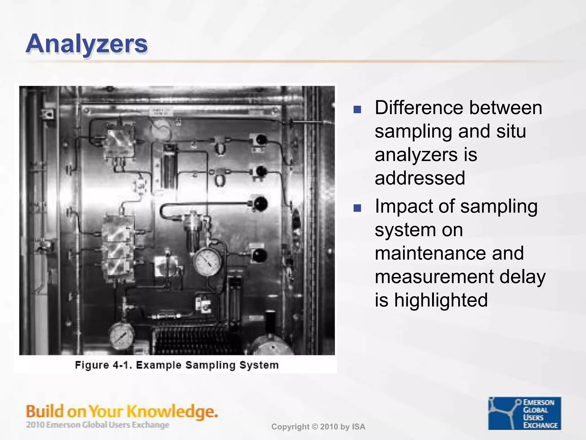
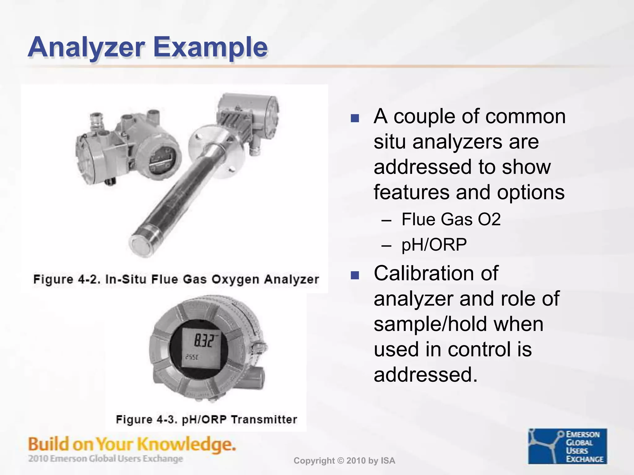
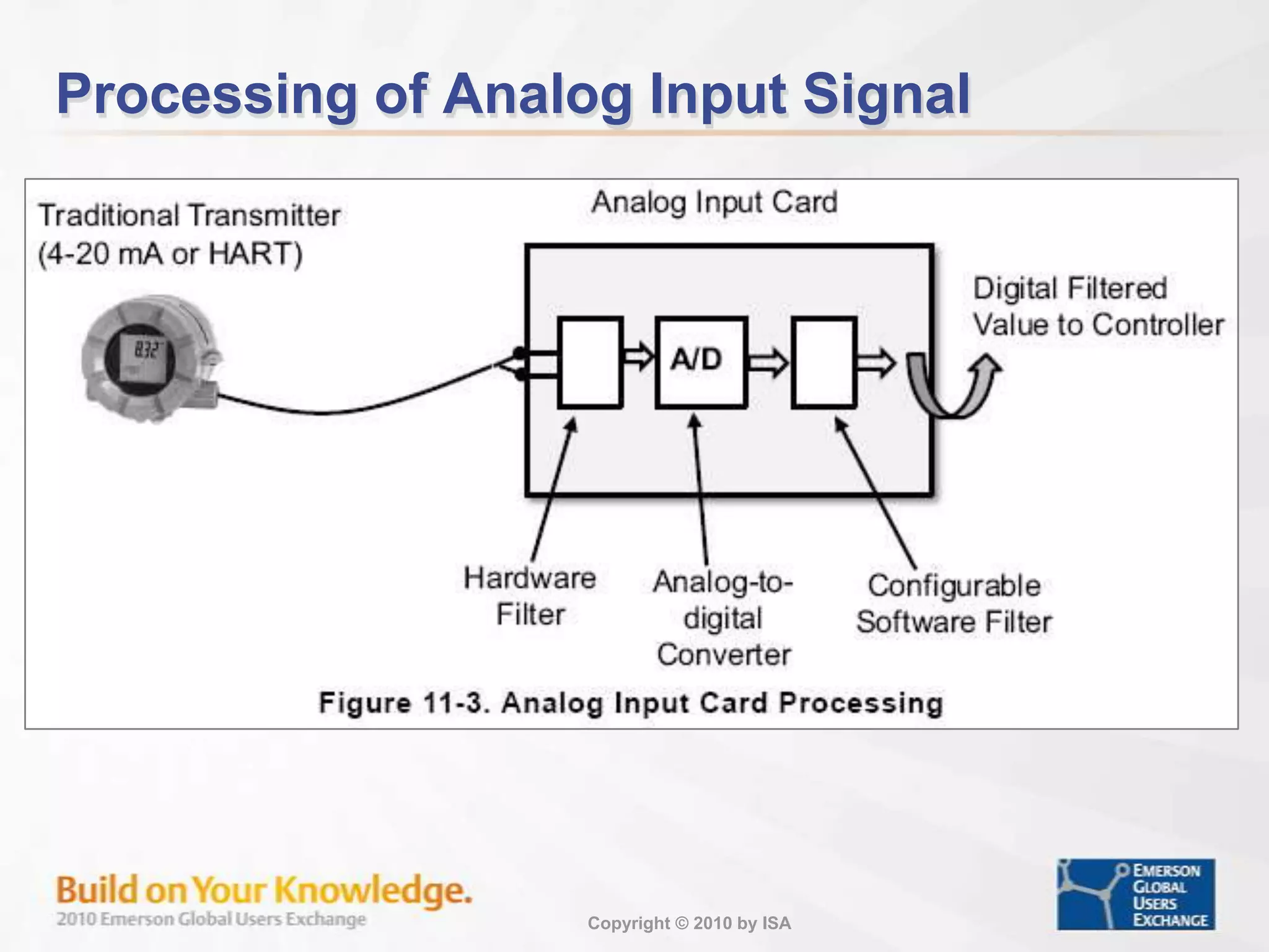
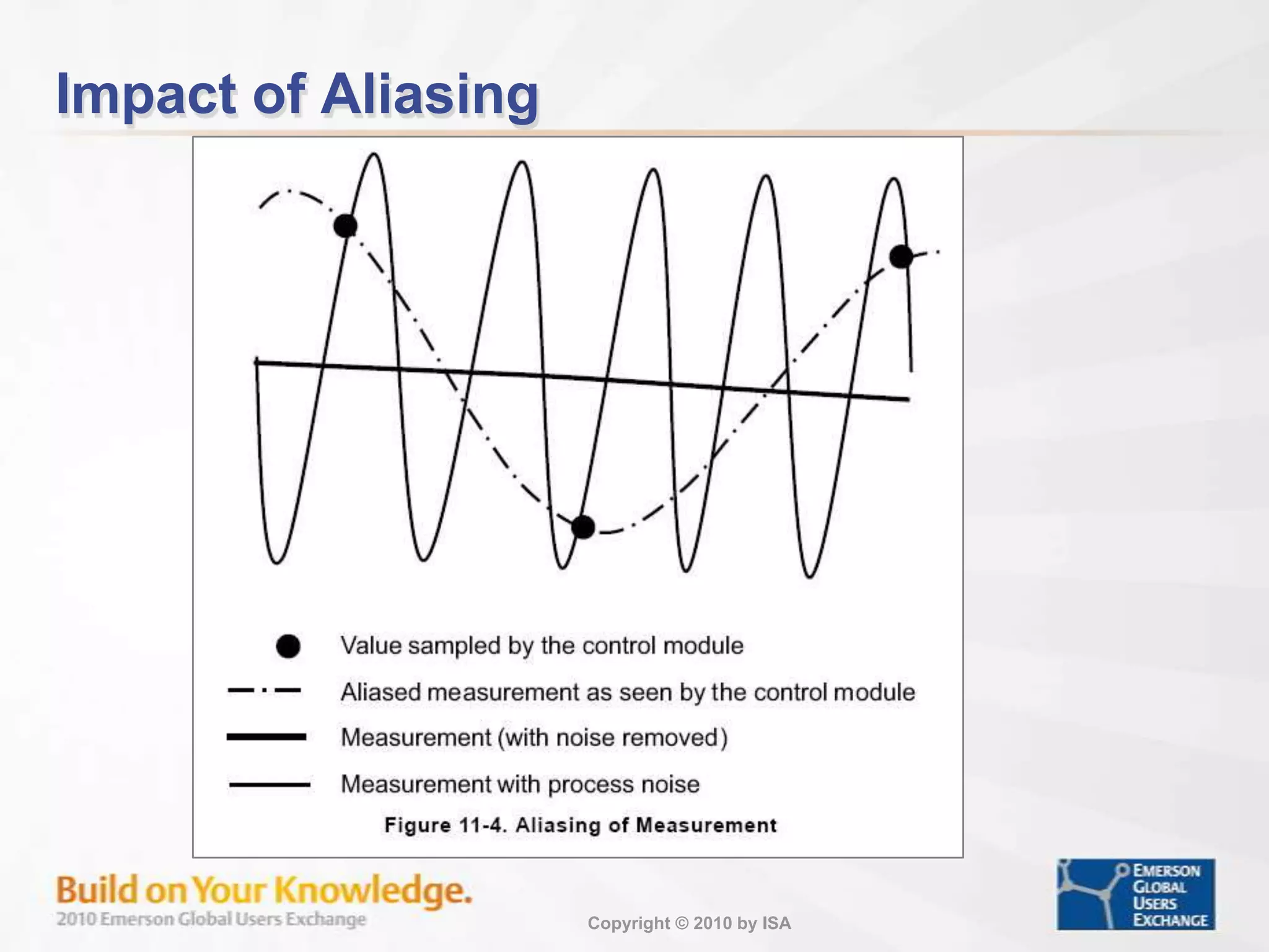
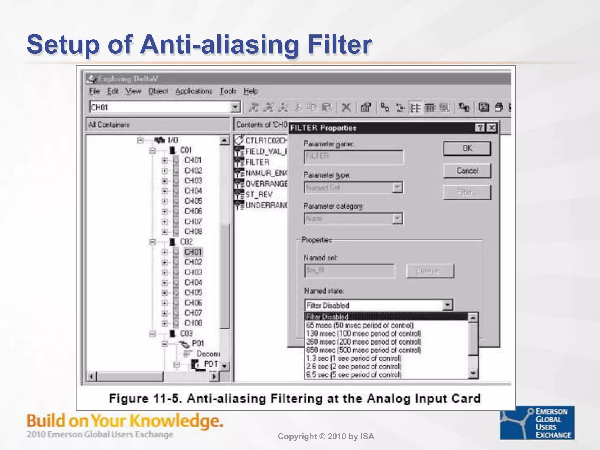
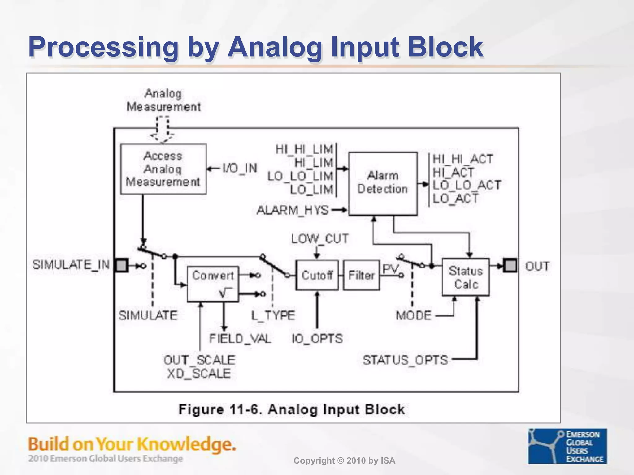
Discussion on measurement devices including flow meters and analyzers, with calibration significance.
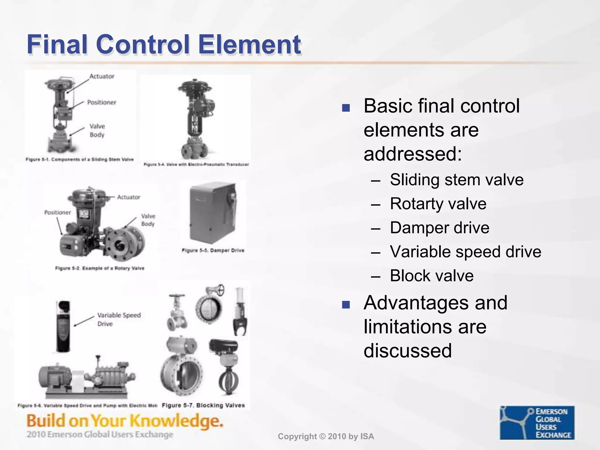
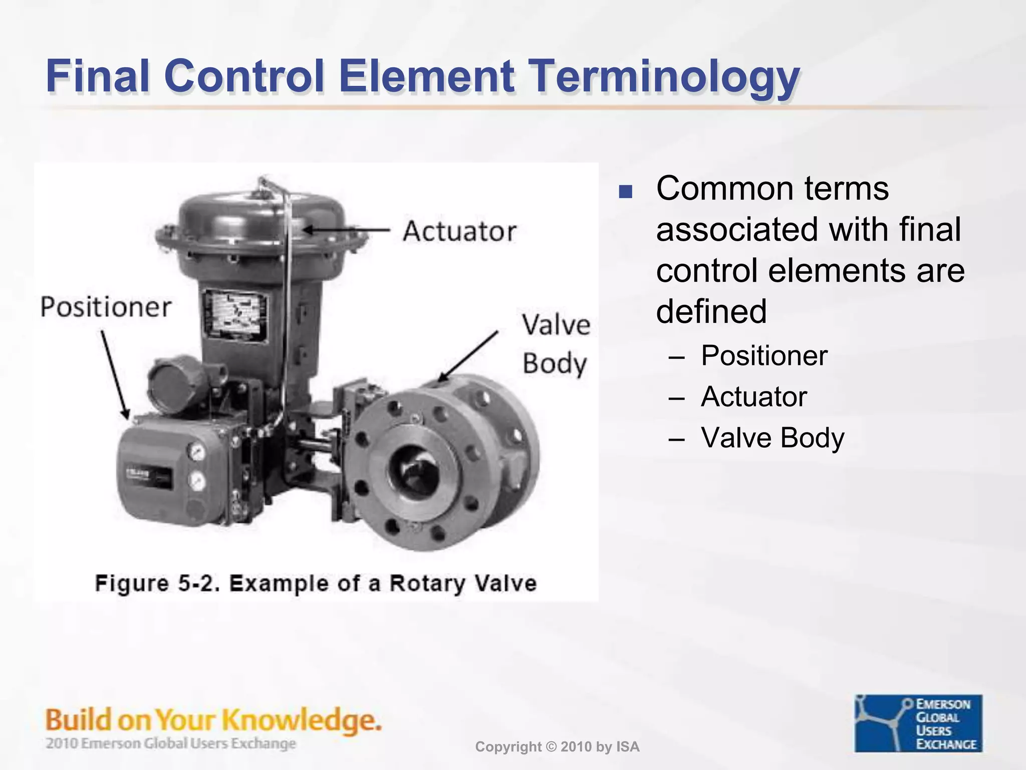
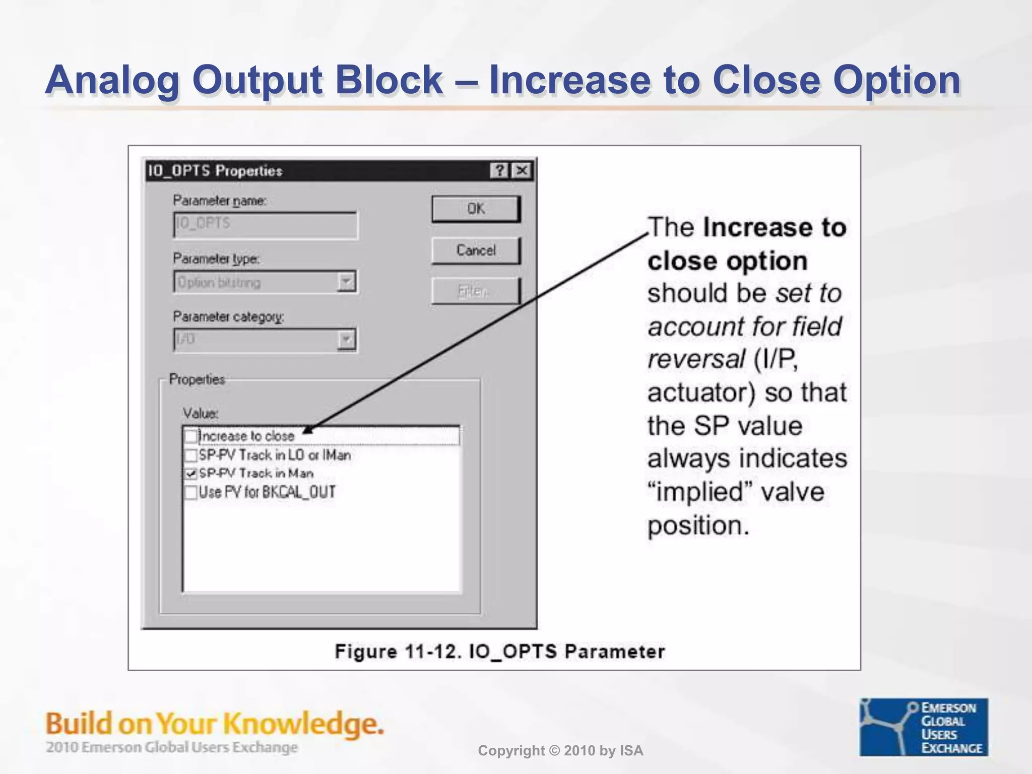
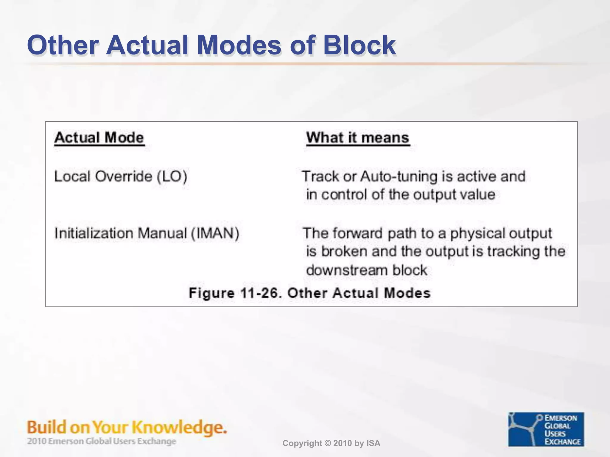
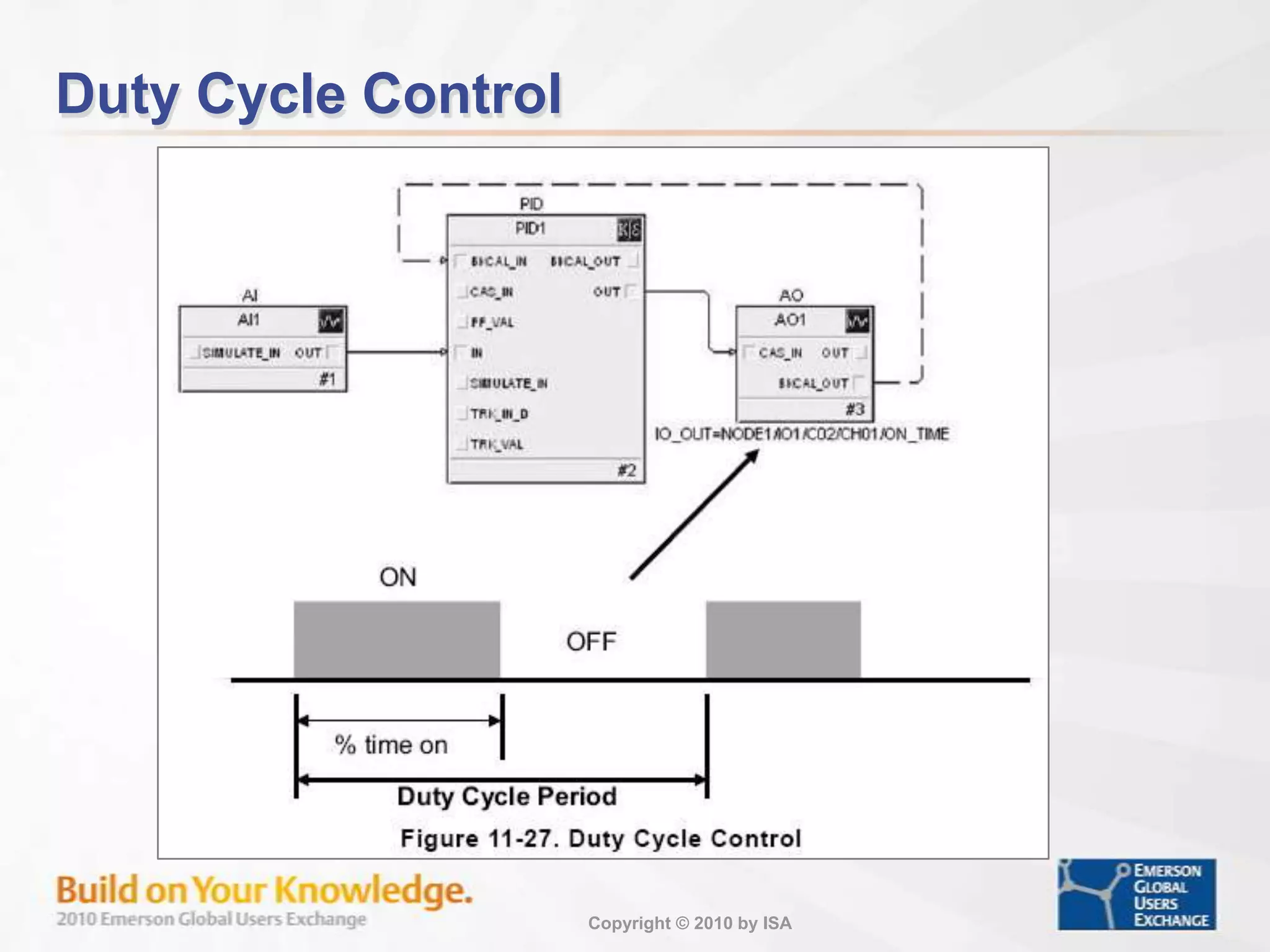
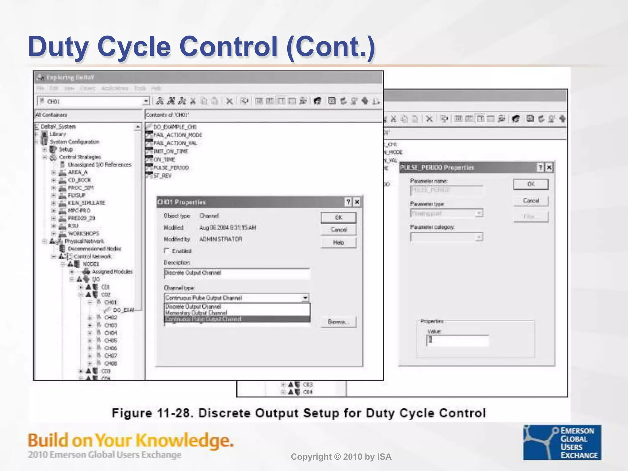
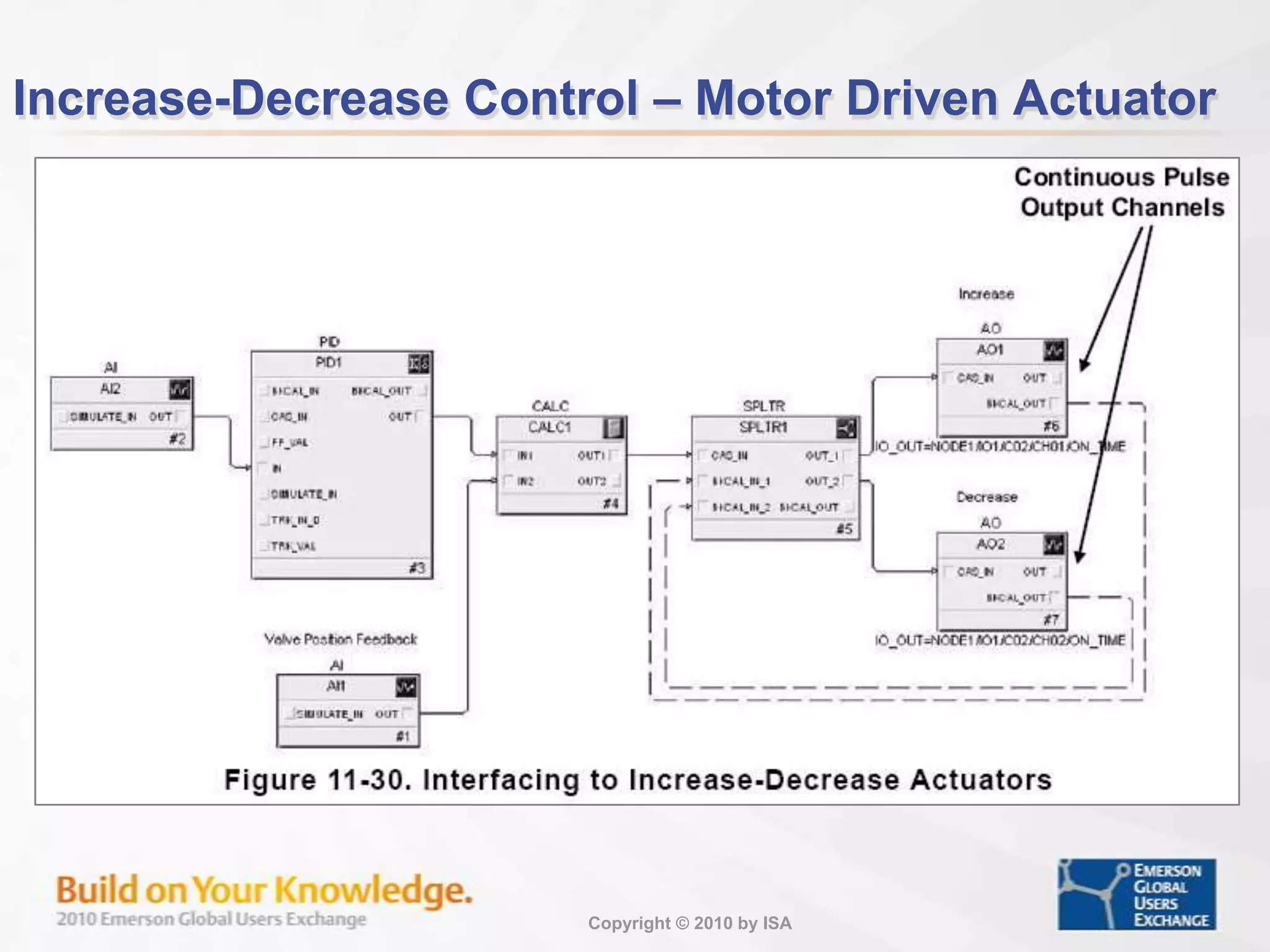
Introduction to final control elements, their types, and essential terminologies associated with them.
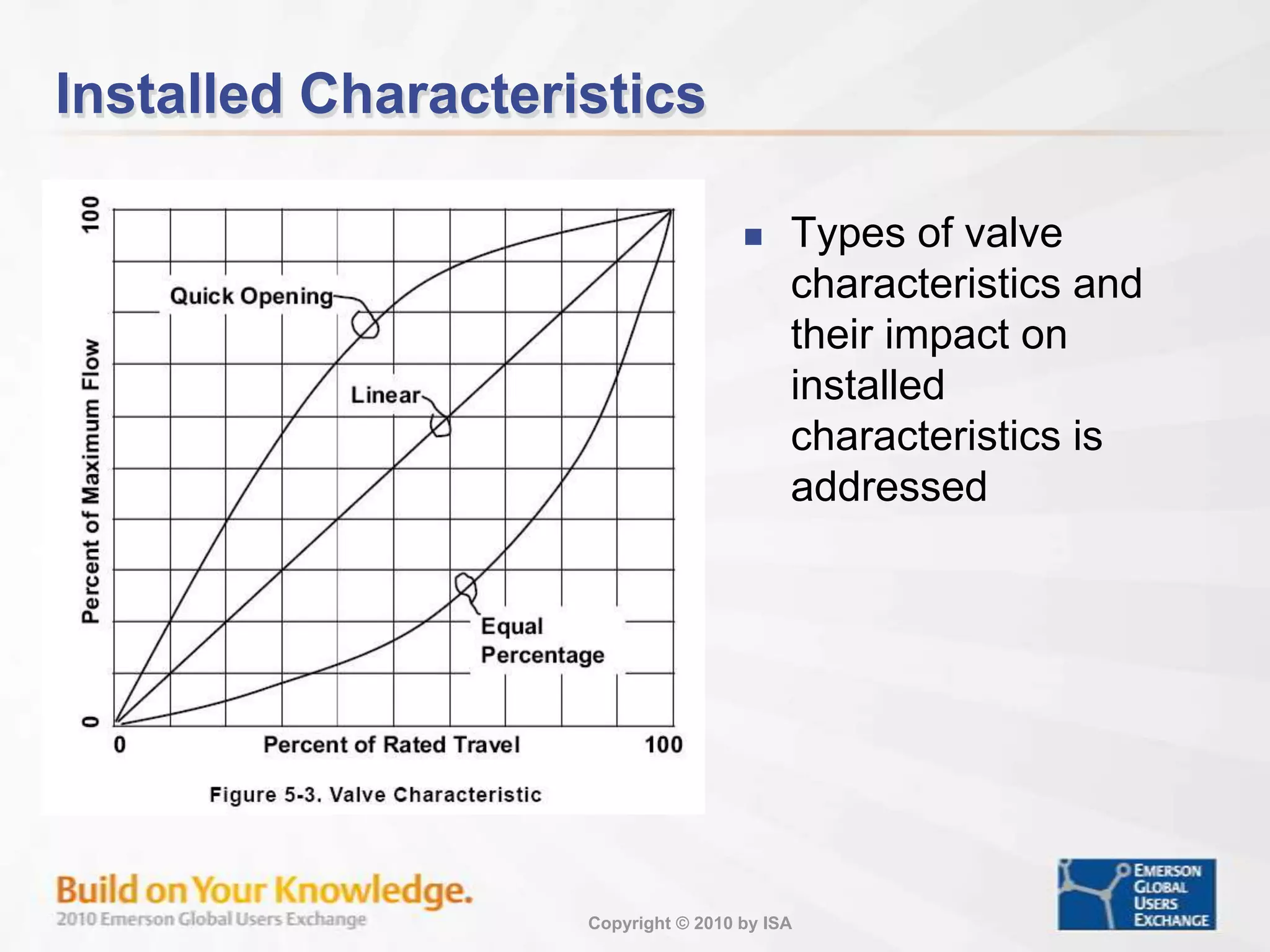
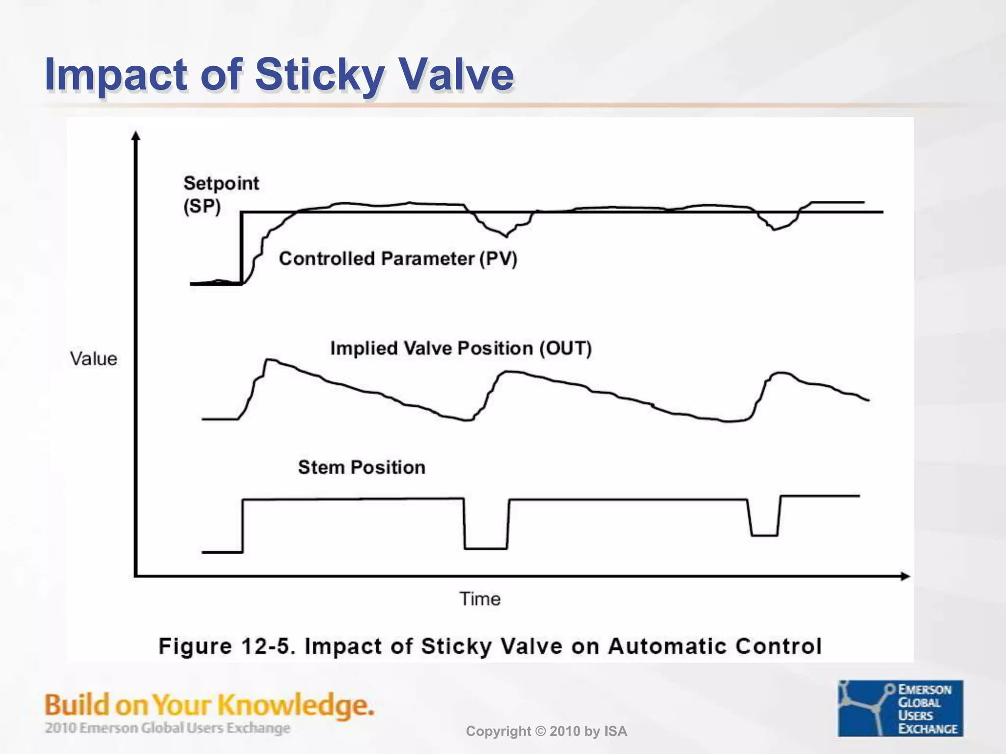
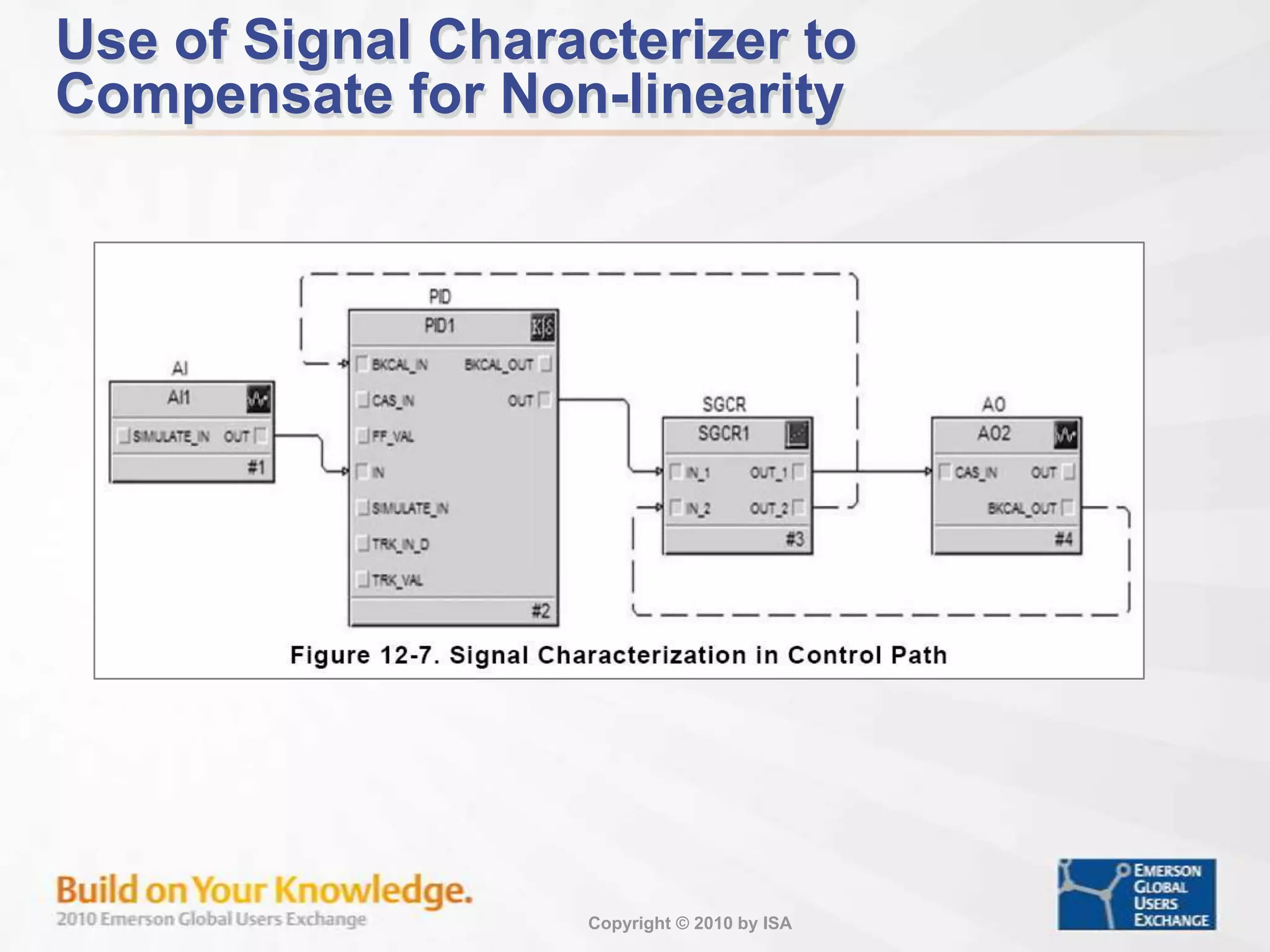
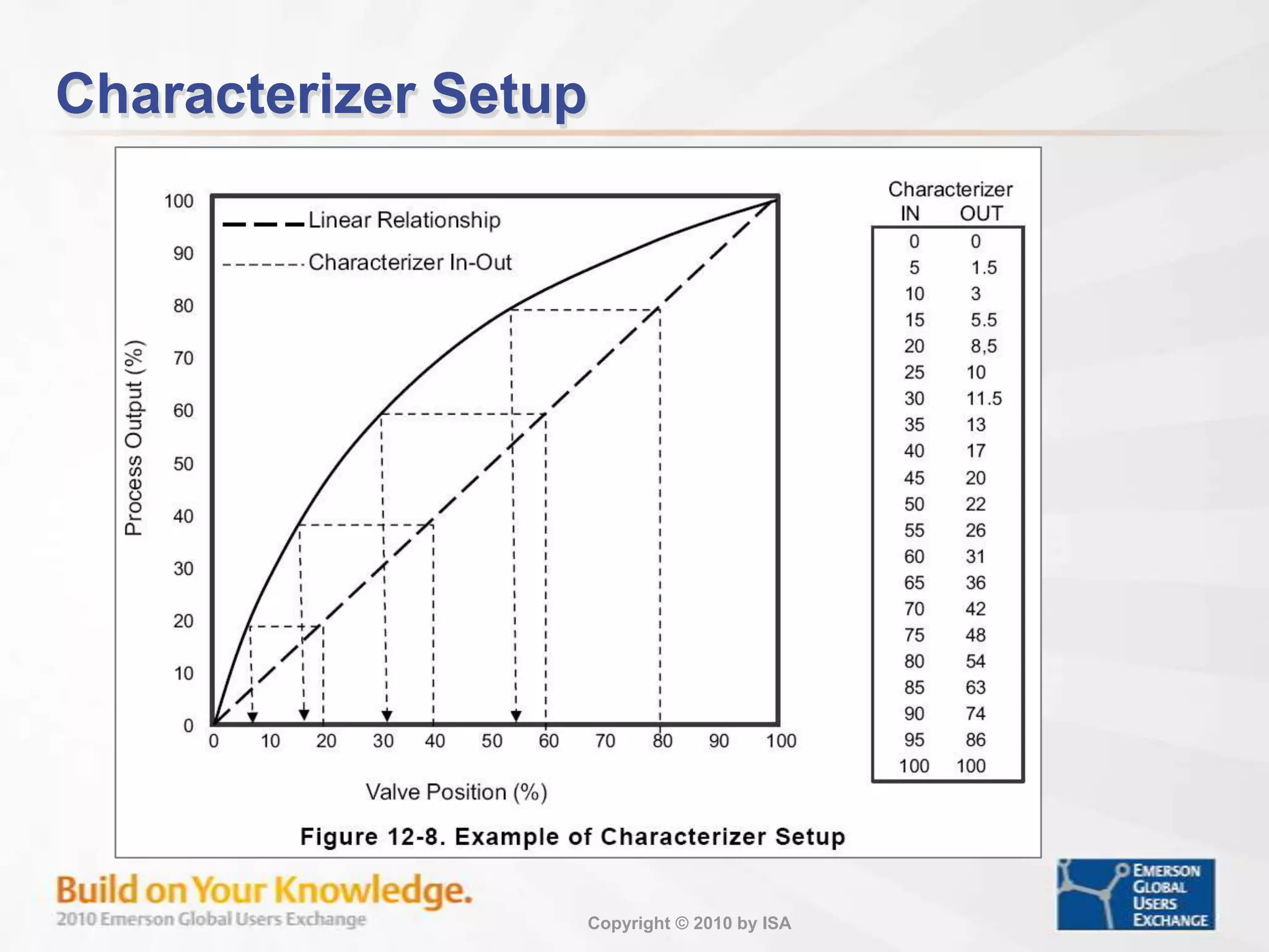
Details on valve characteristics and wiring installations that affect control signal integrity.
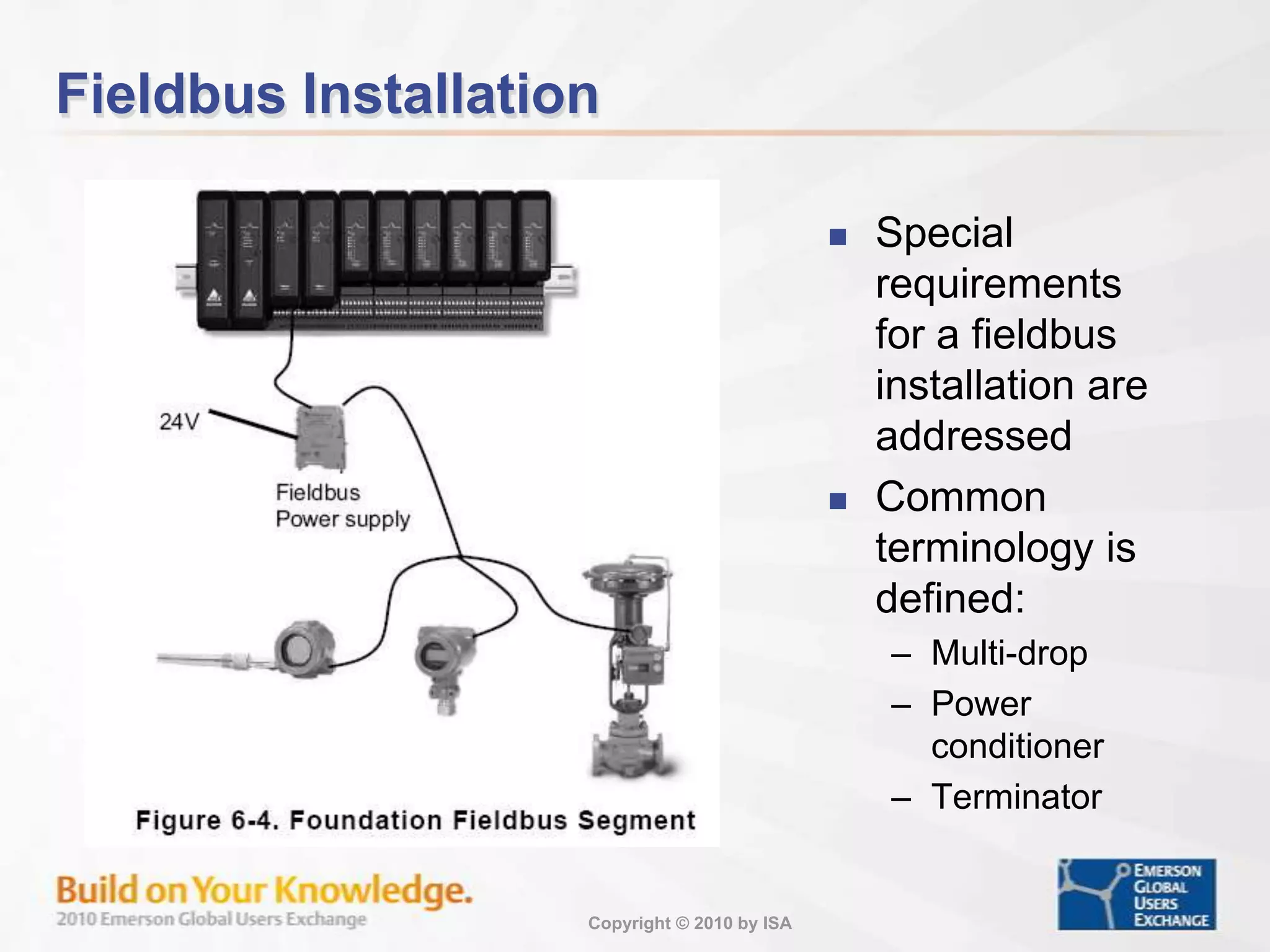
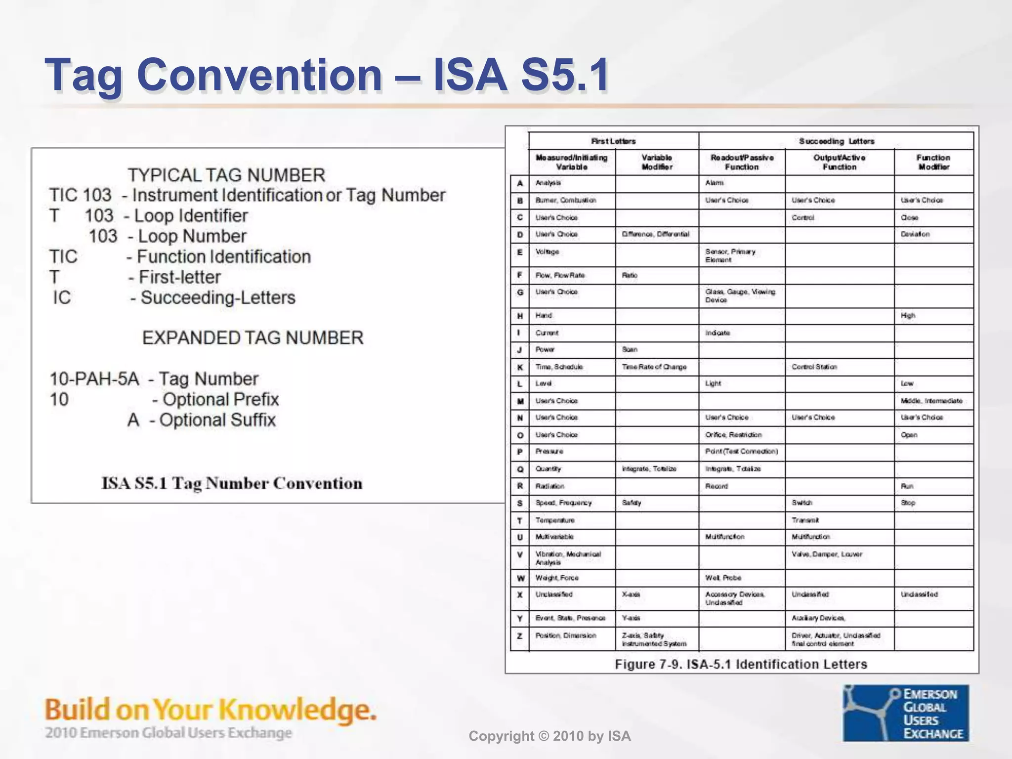
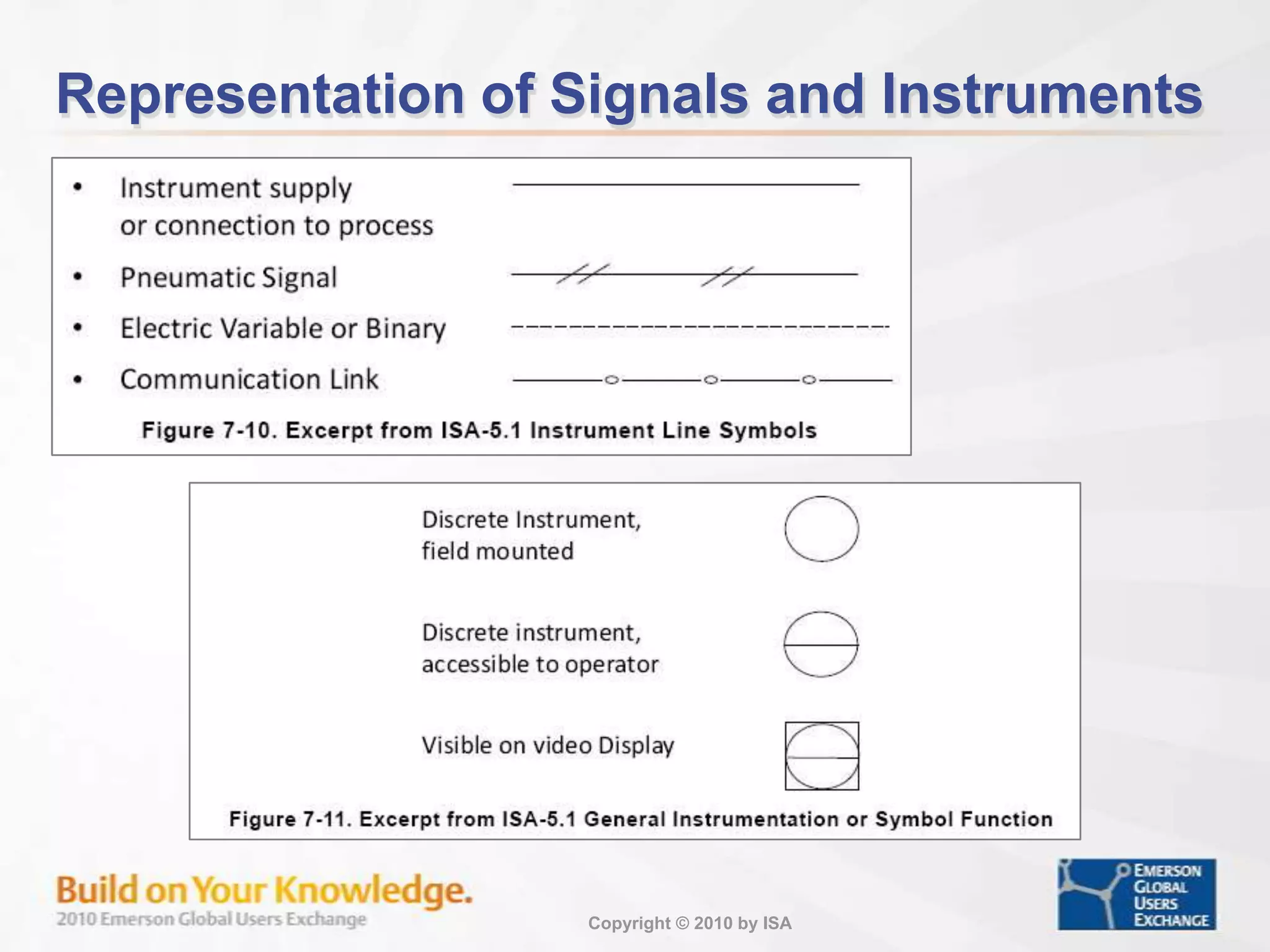
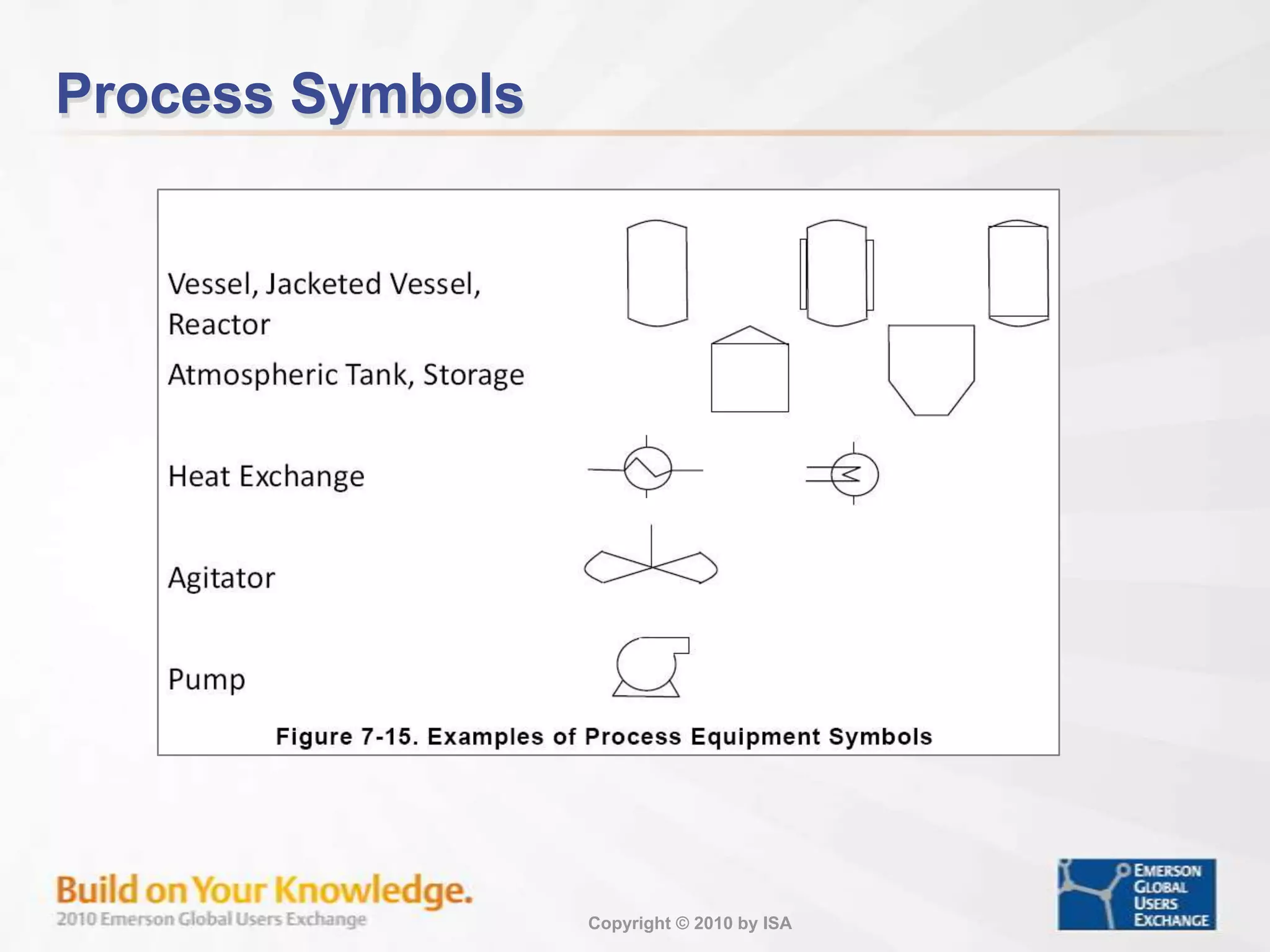
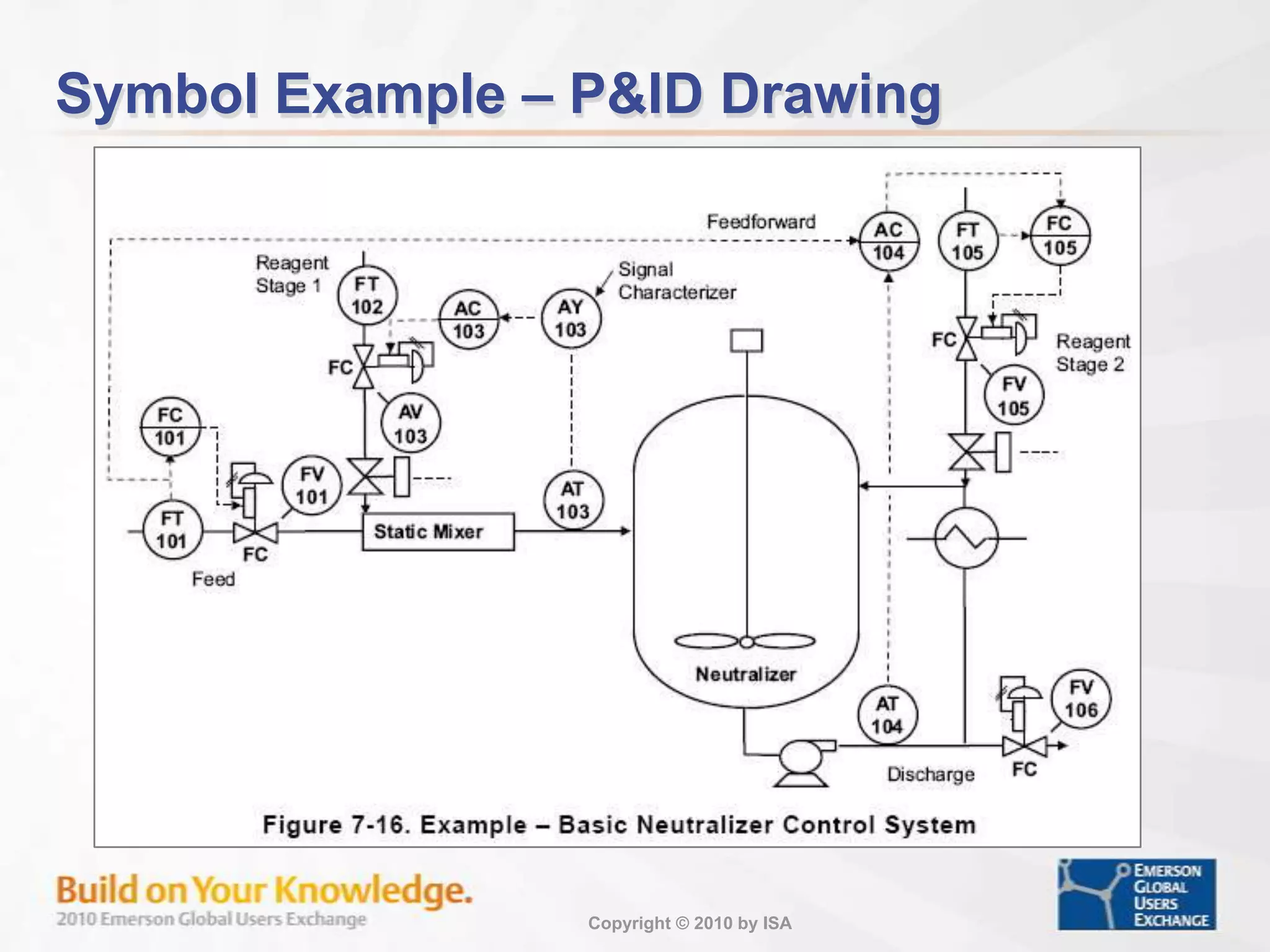
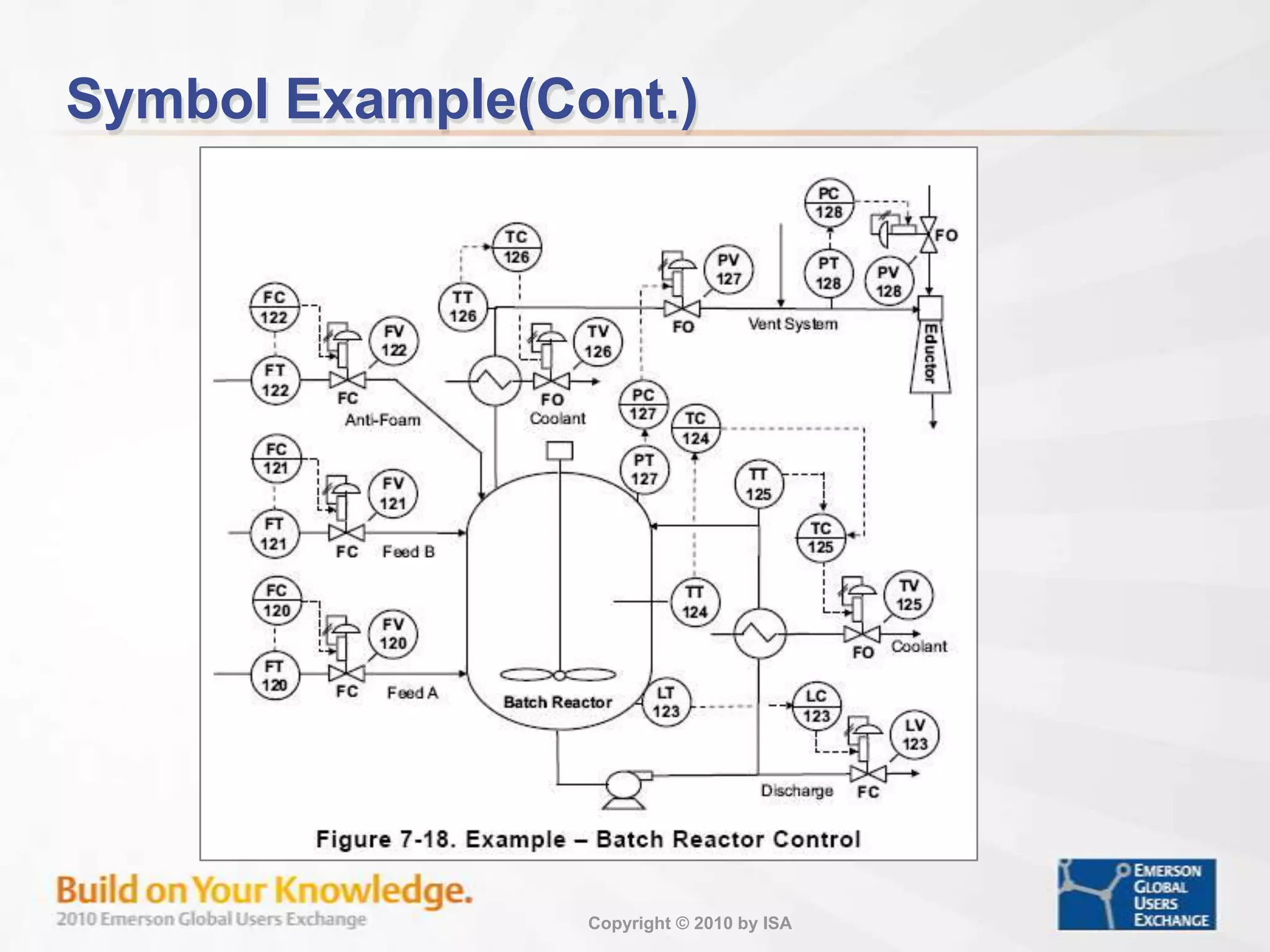
Documentation essentials for control system installations including tag conventions and signal representations.
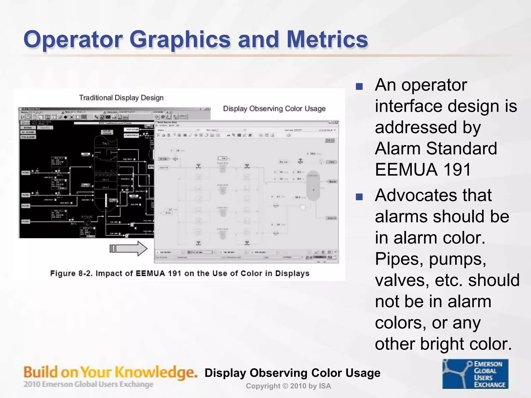
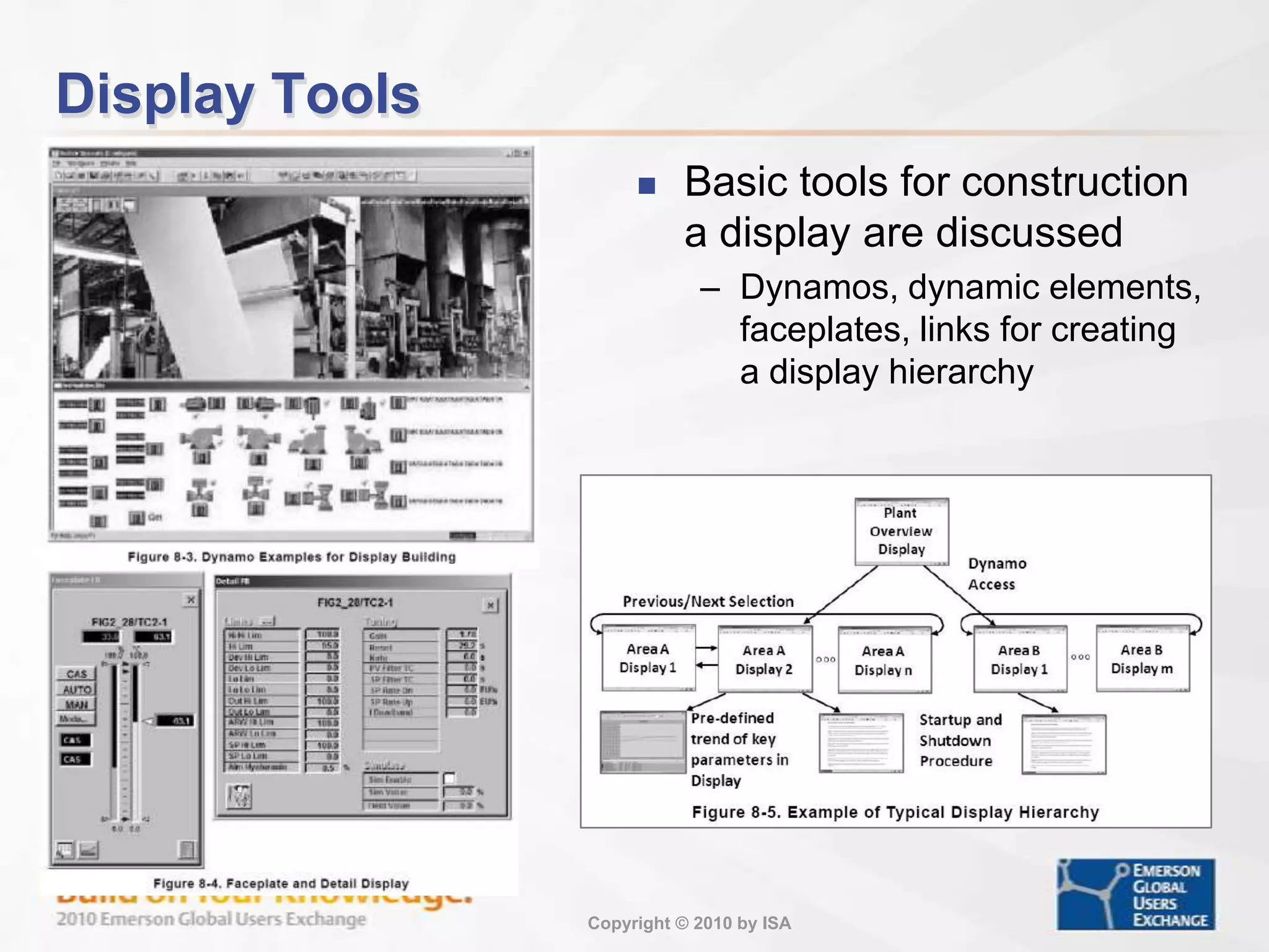
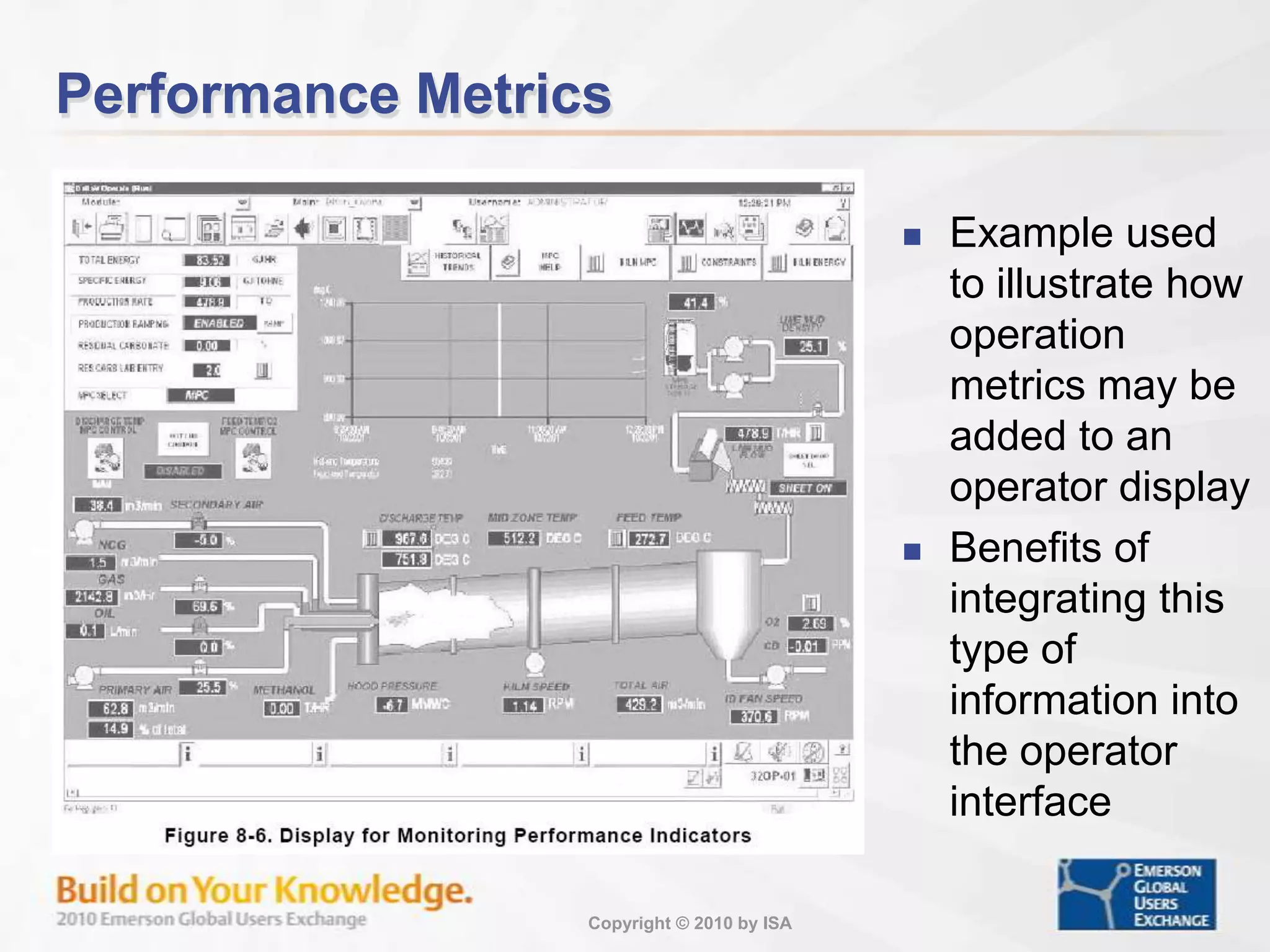
Design considerations for operator interfaces, emphasizing alarm standards and metrics integration.
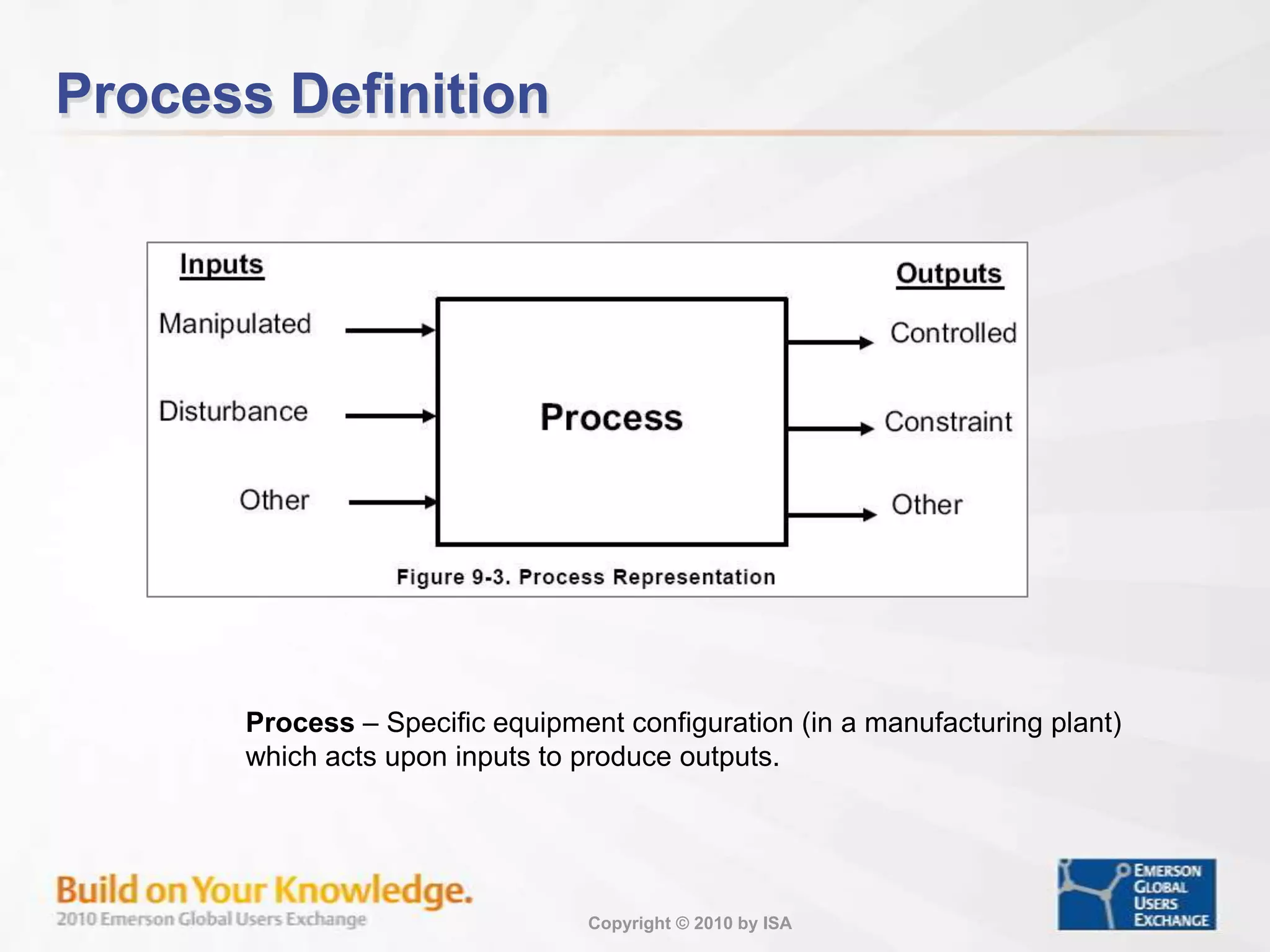
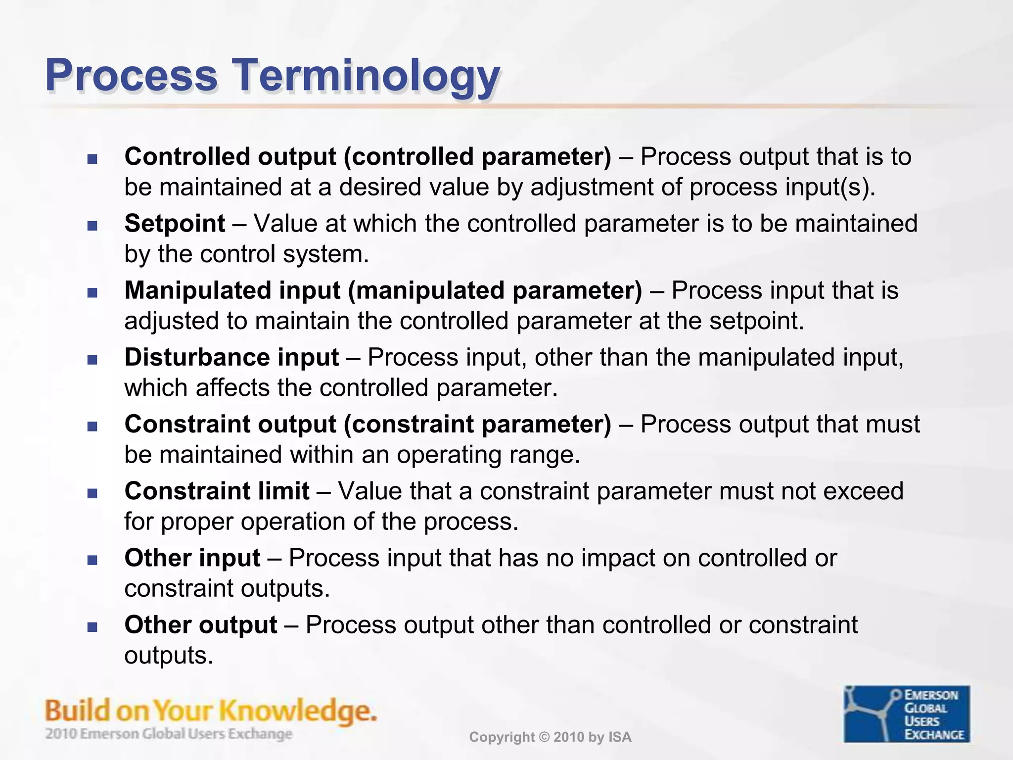
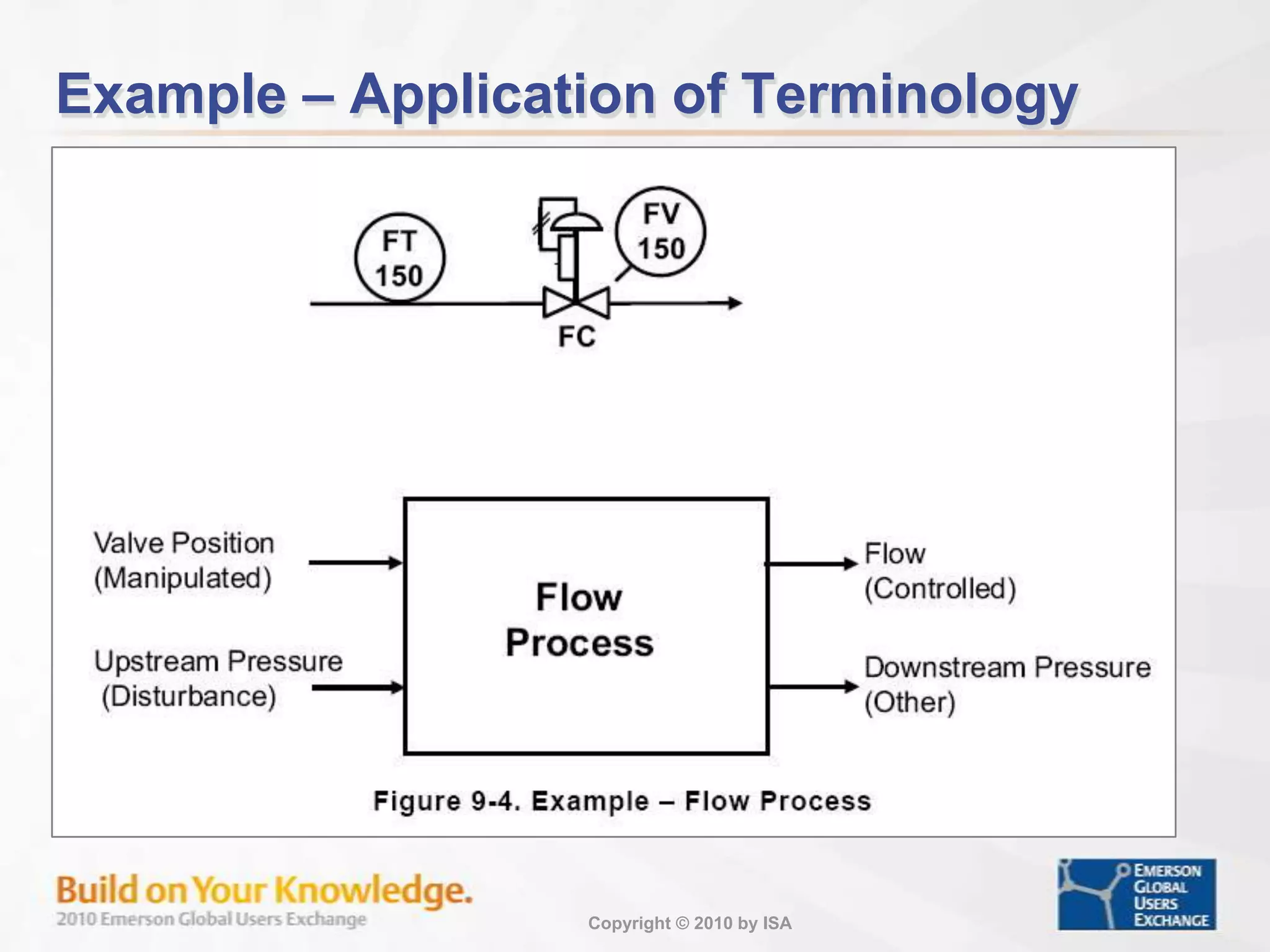
Definitions of various process terms crucial for understanding control dynamics in a plant.
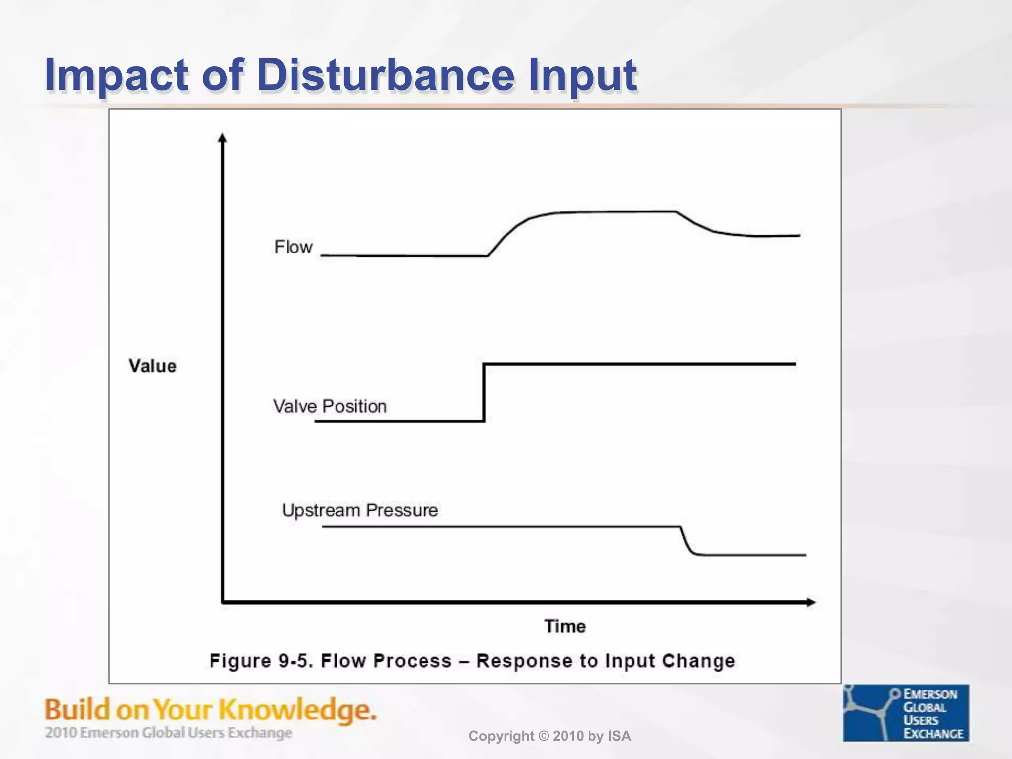
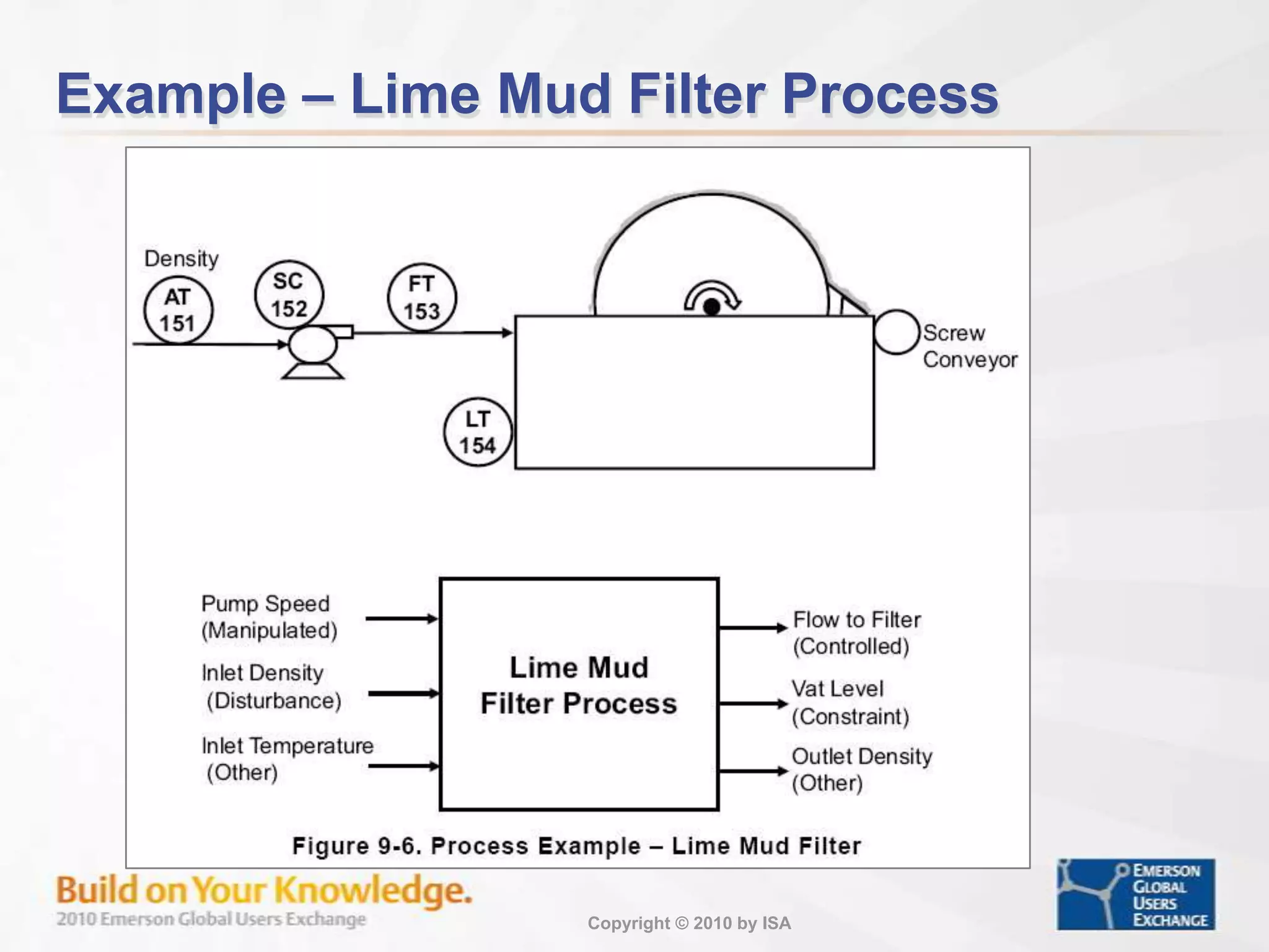
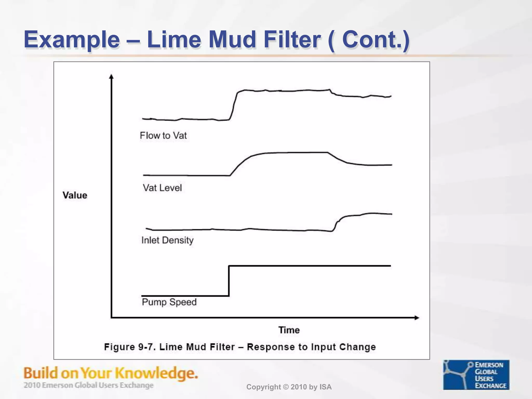
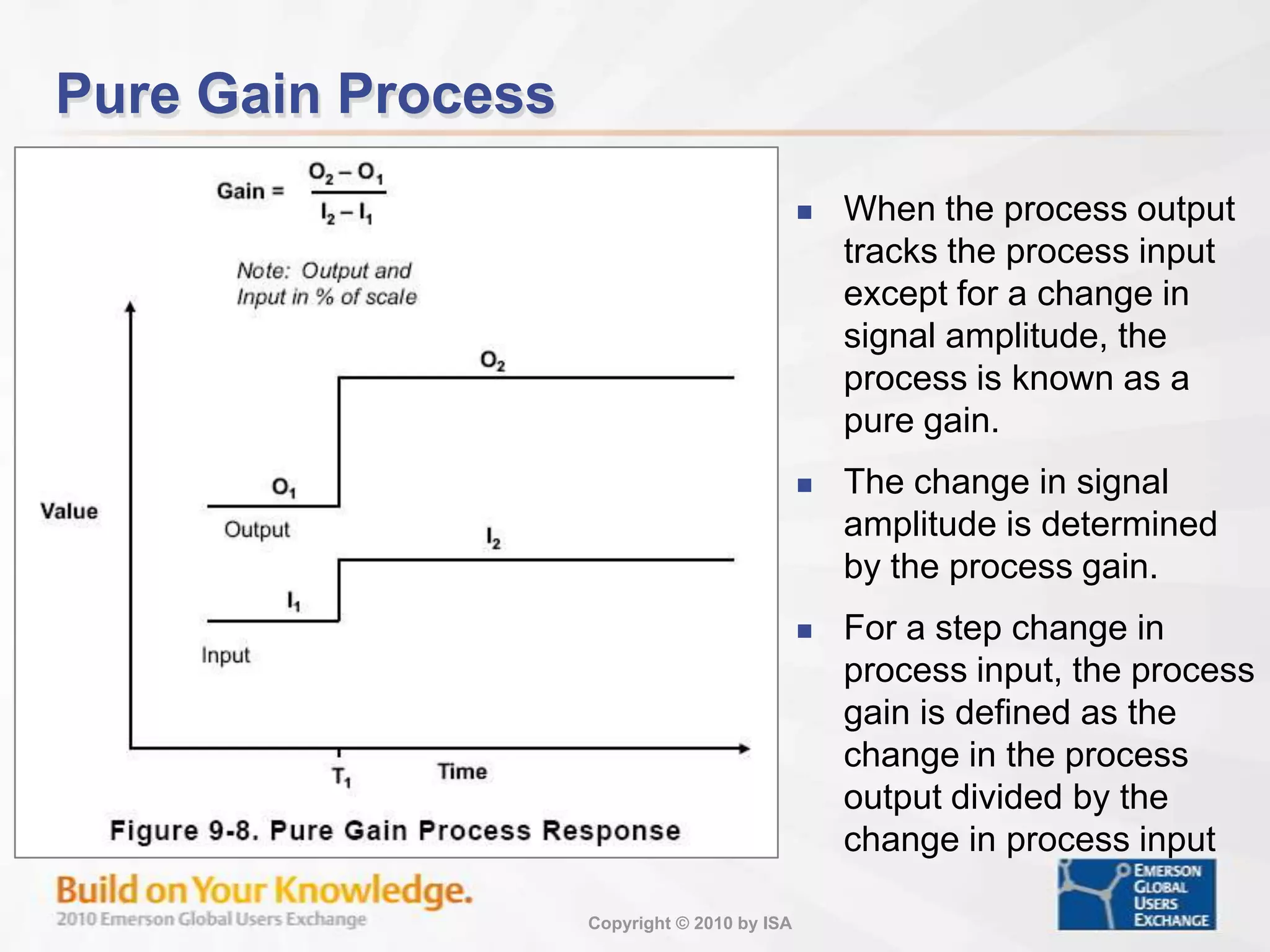
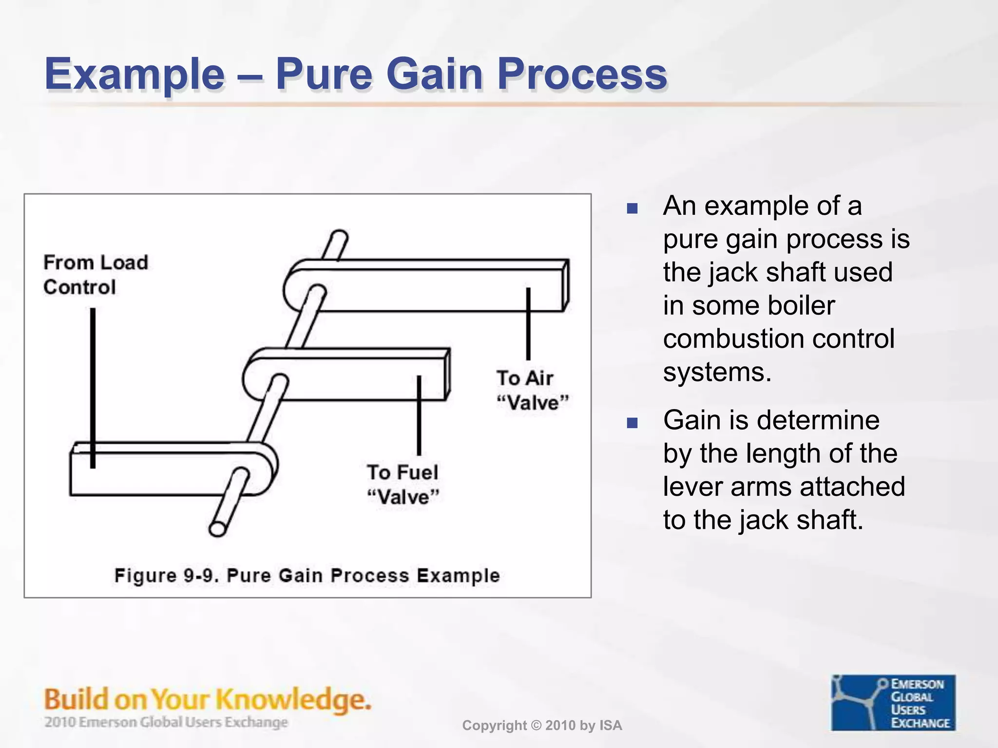
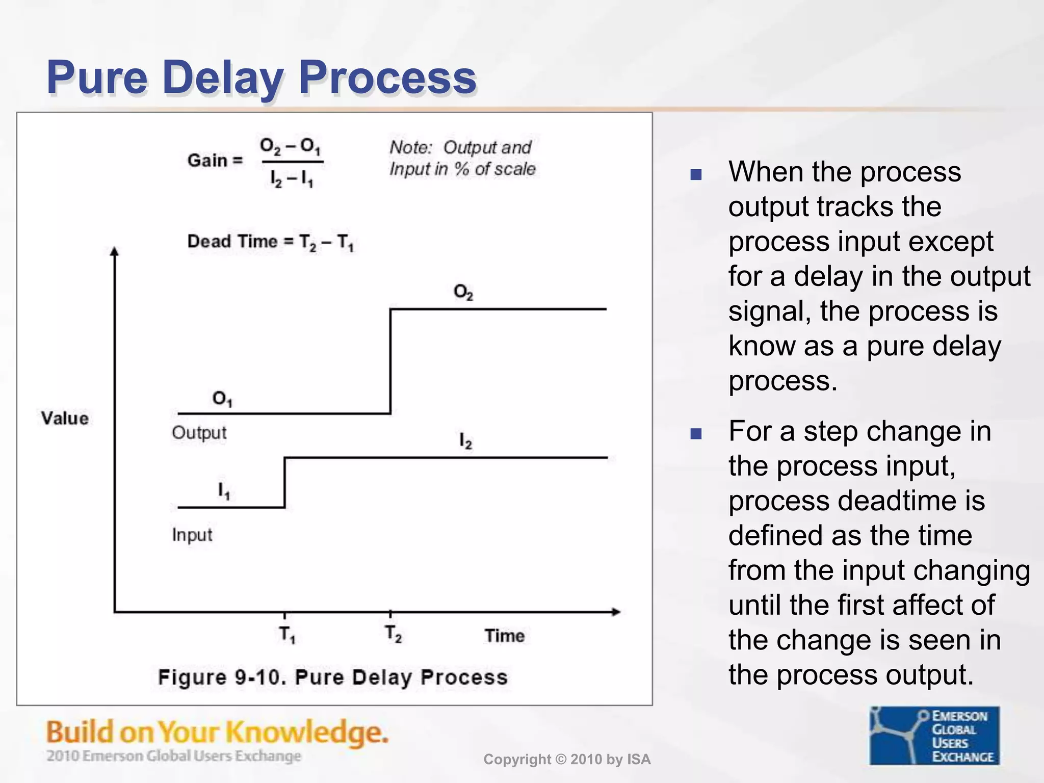
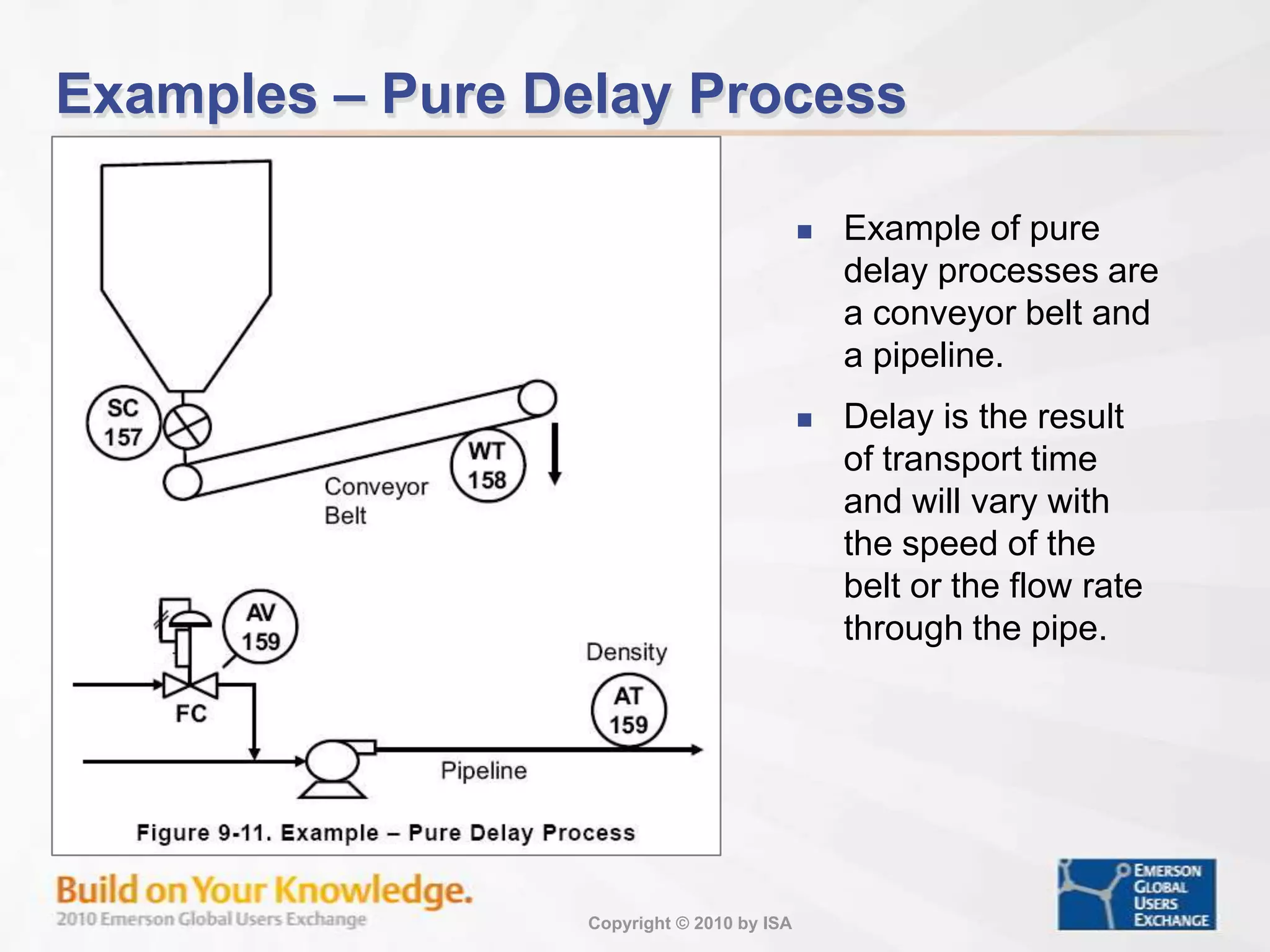
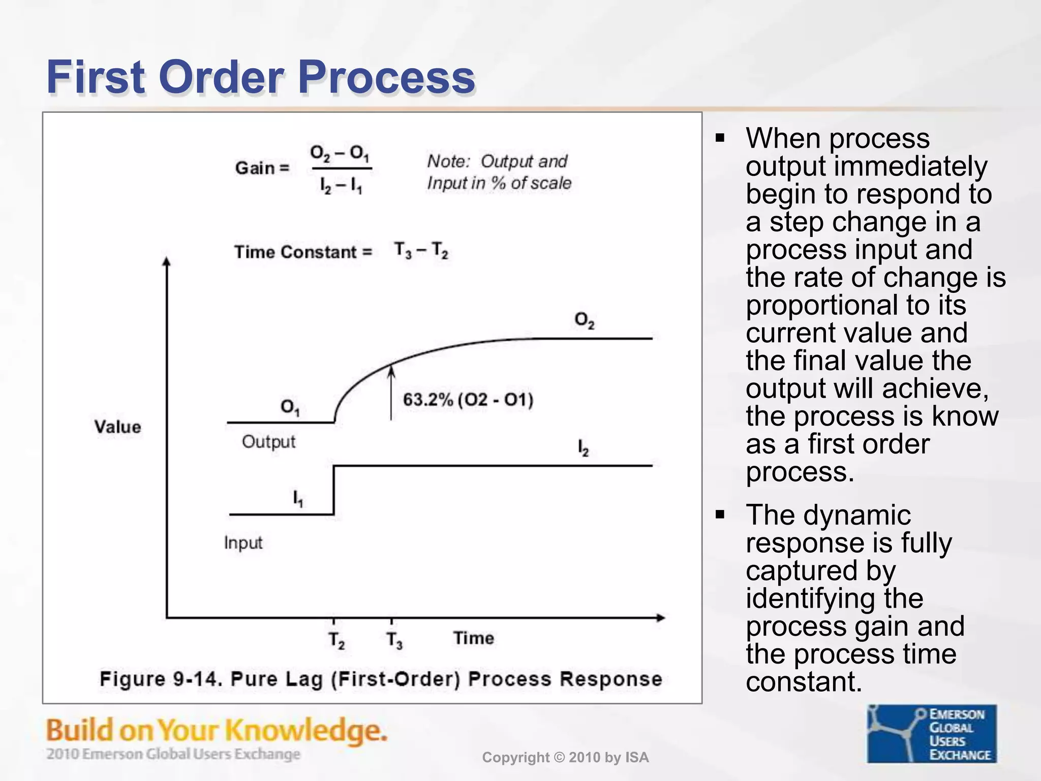
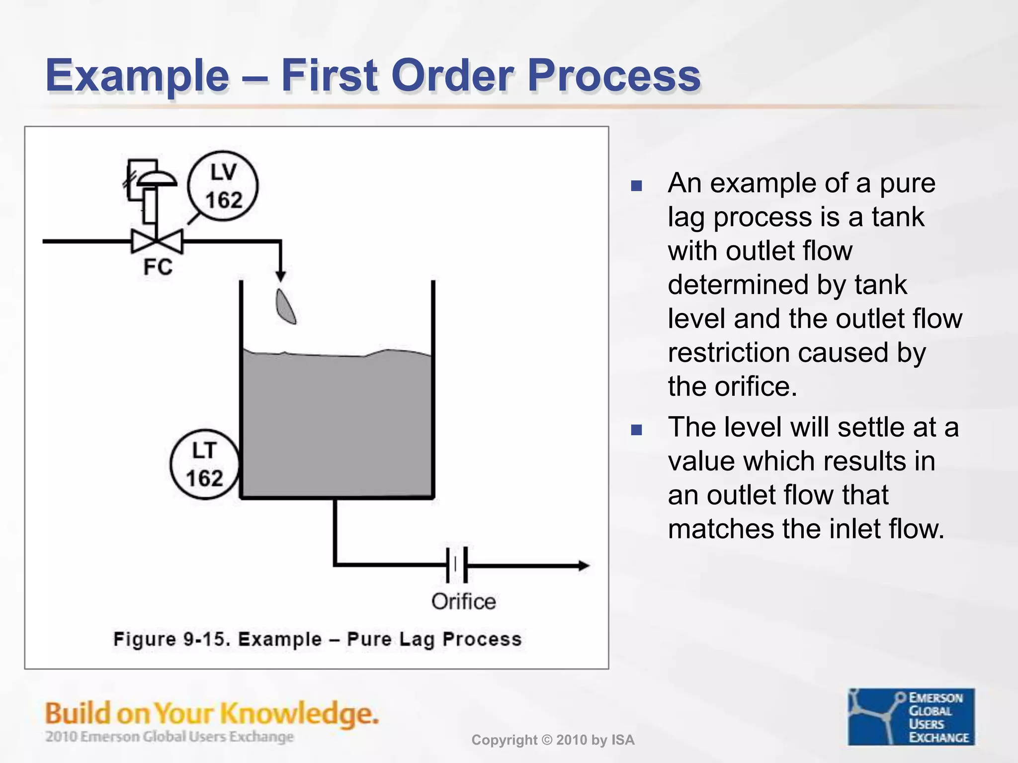
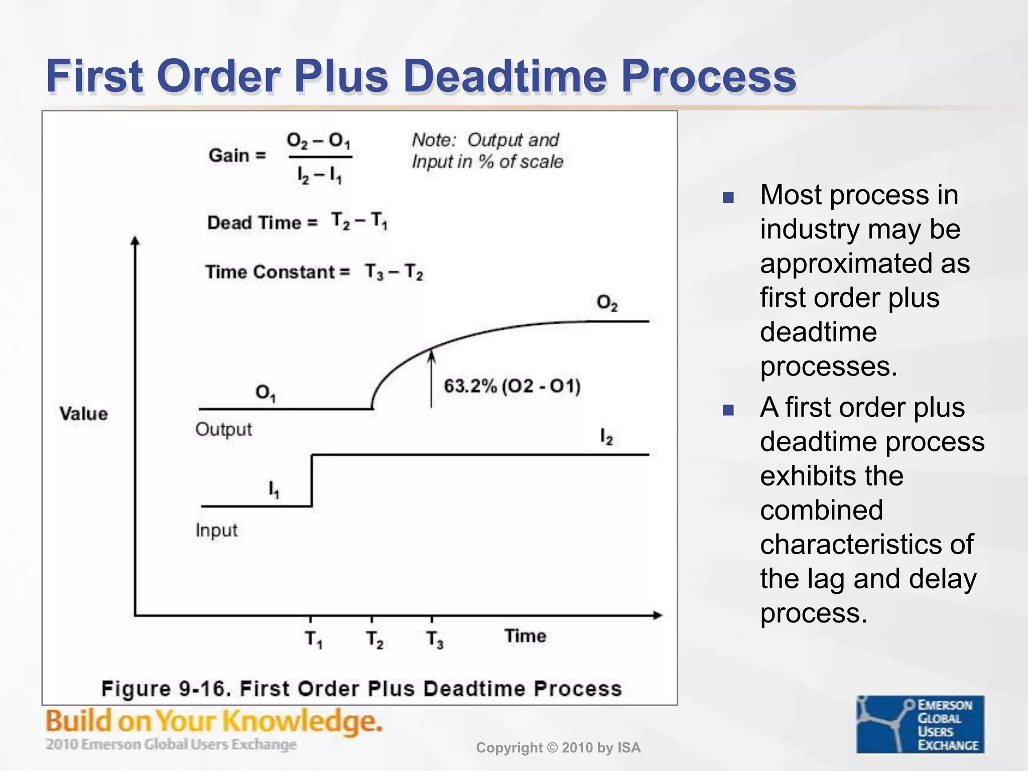
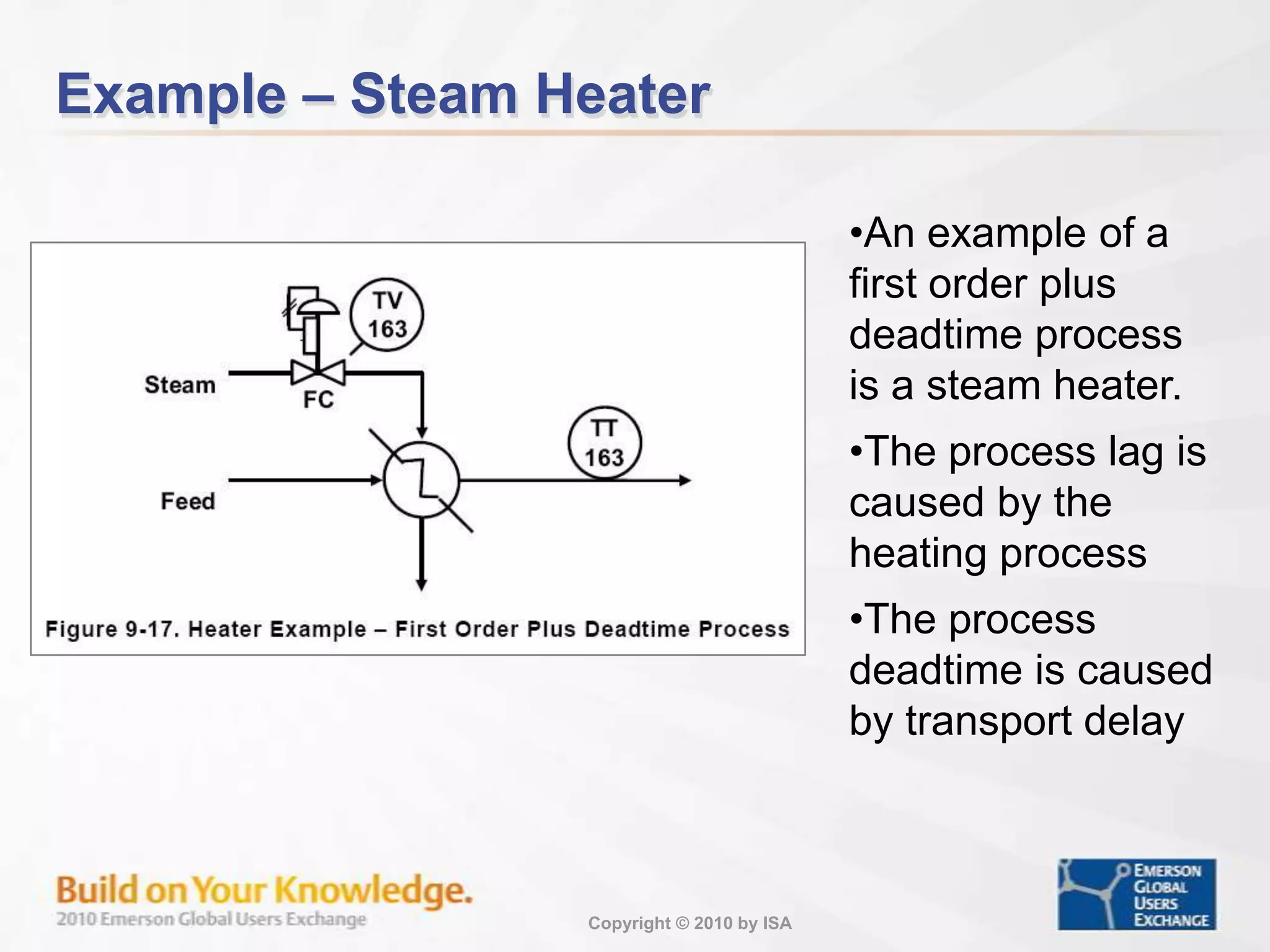
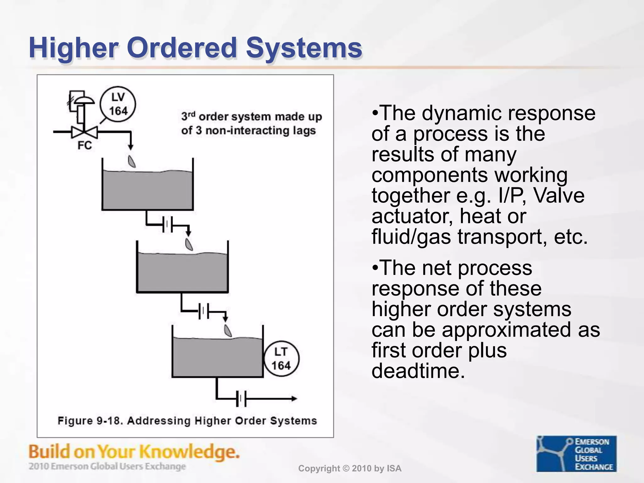
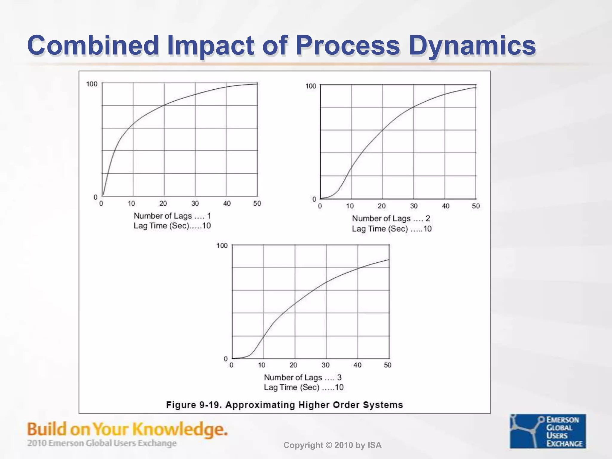
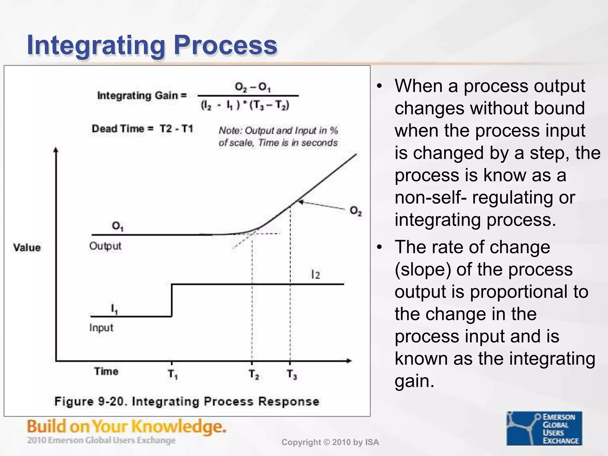
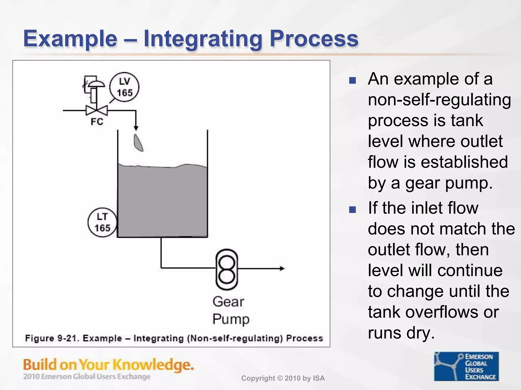
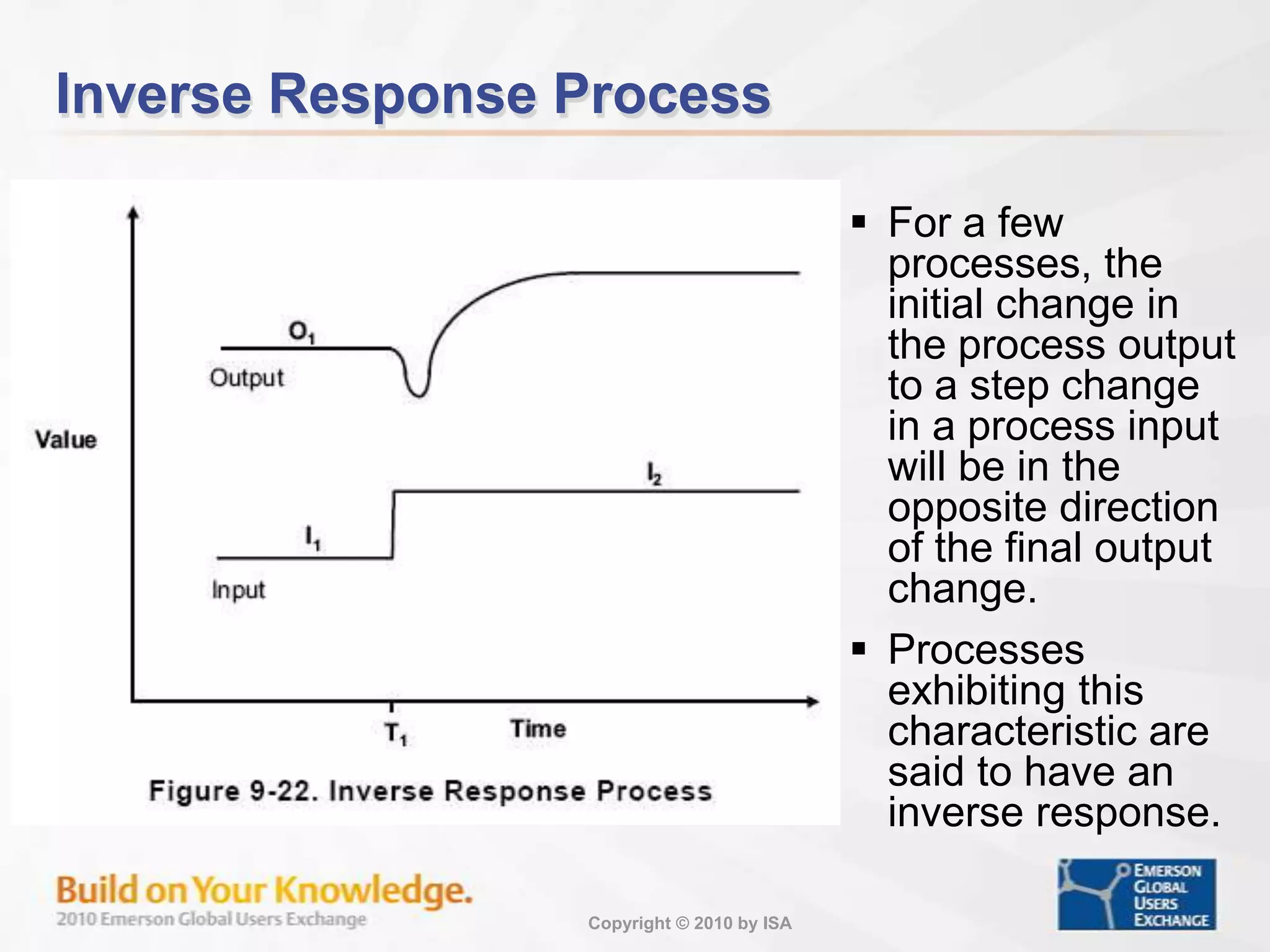
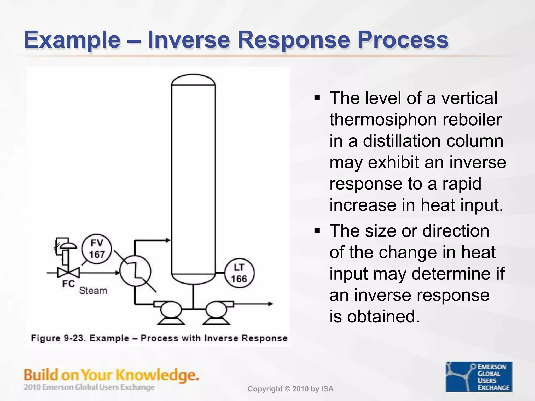
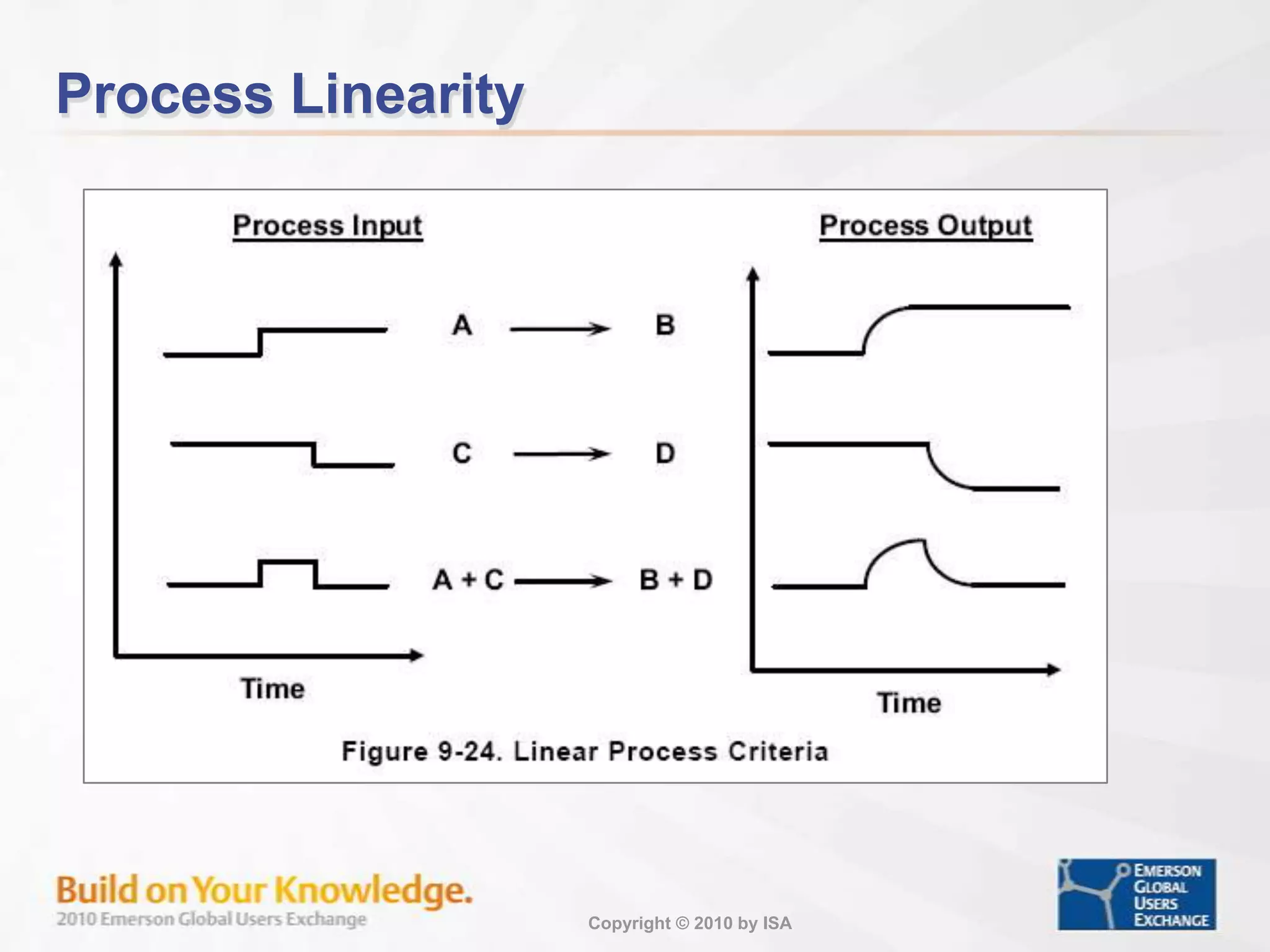
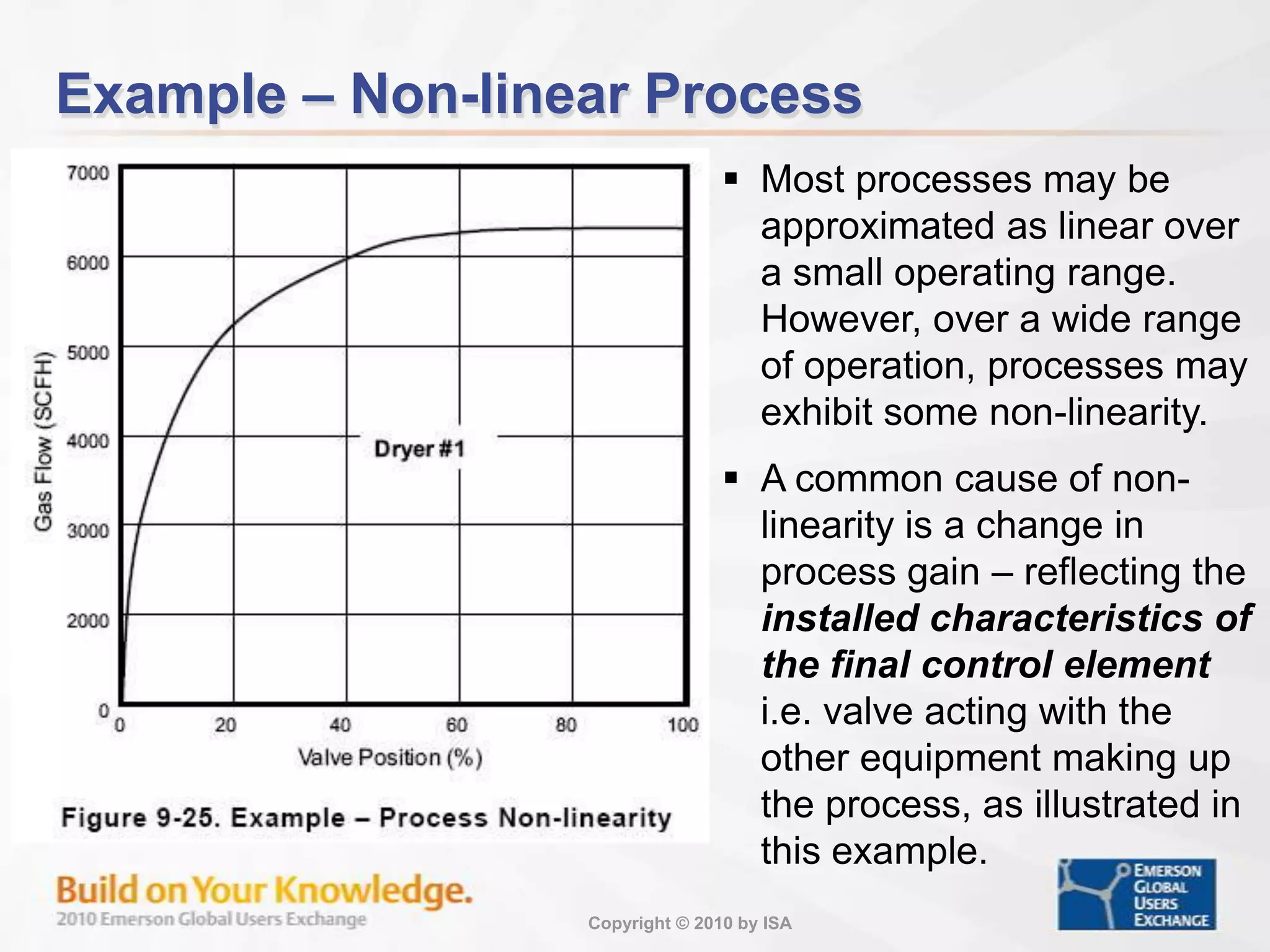
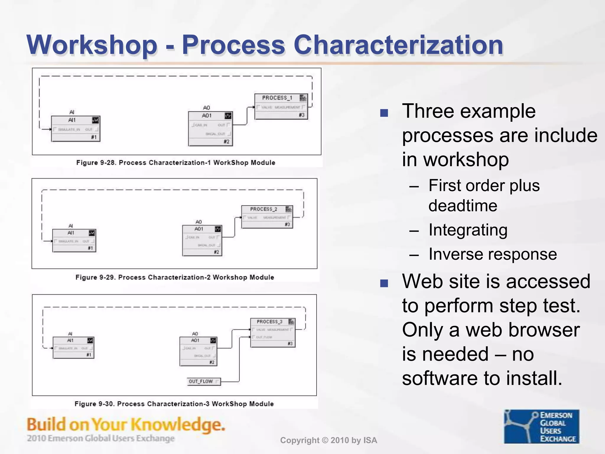
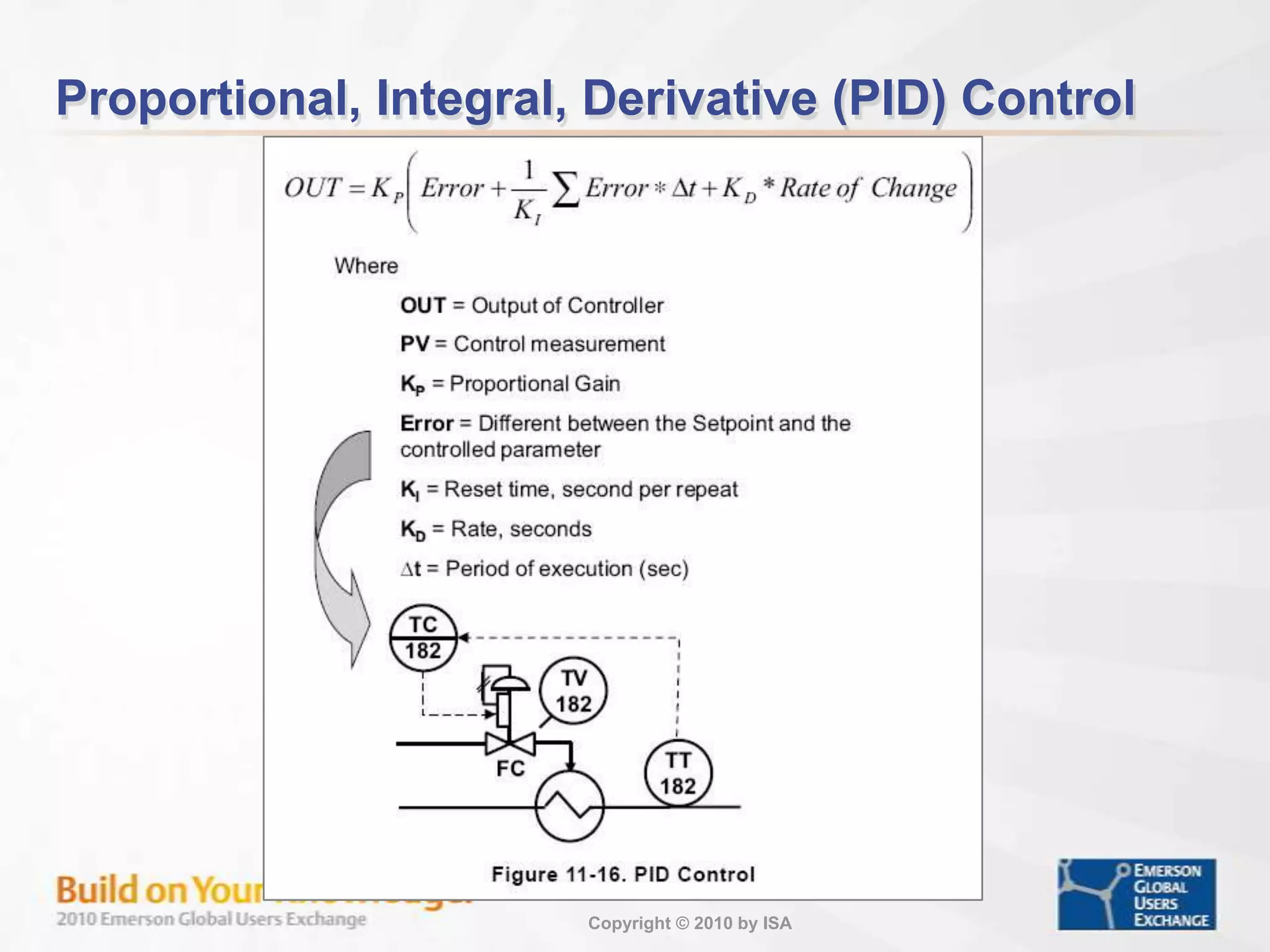
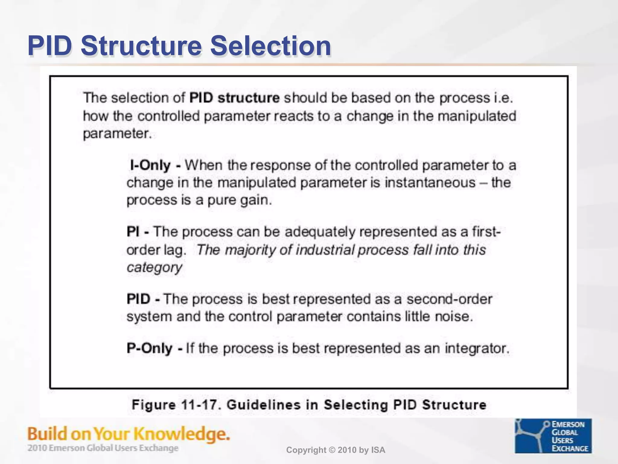
Examples of different process types and their responses to inputs, including pure gain and delay.
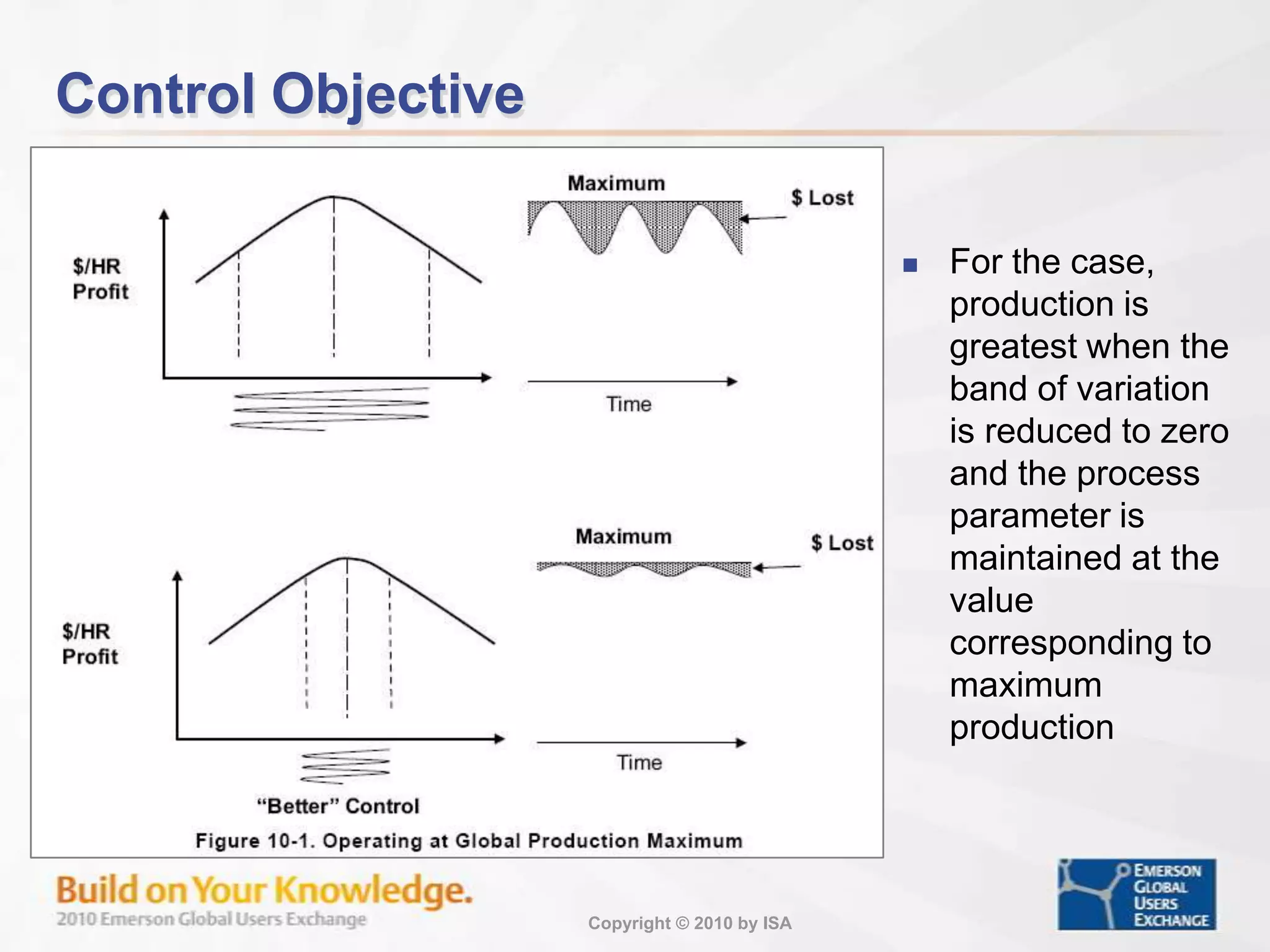
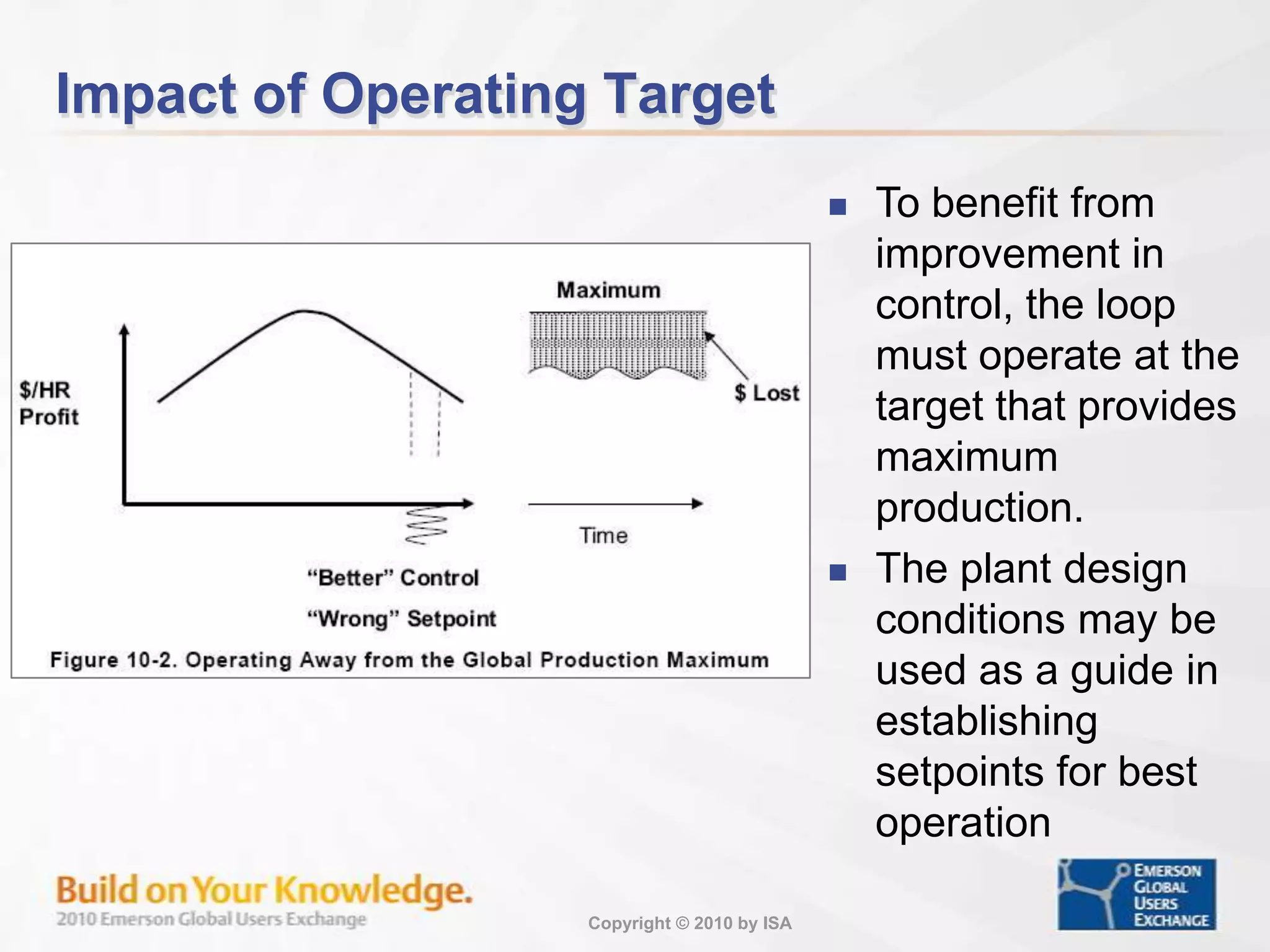
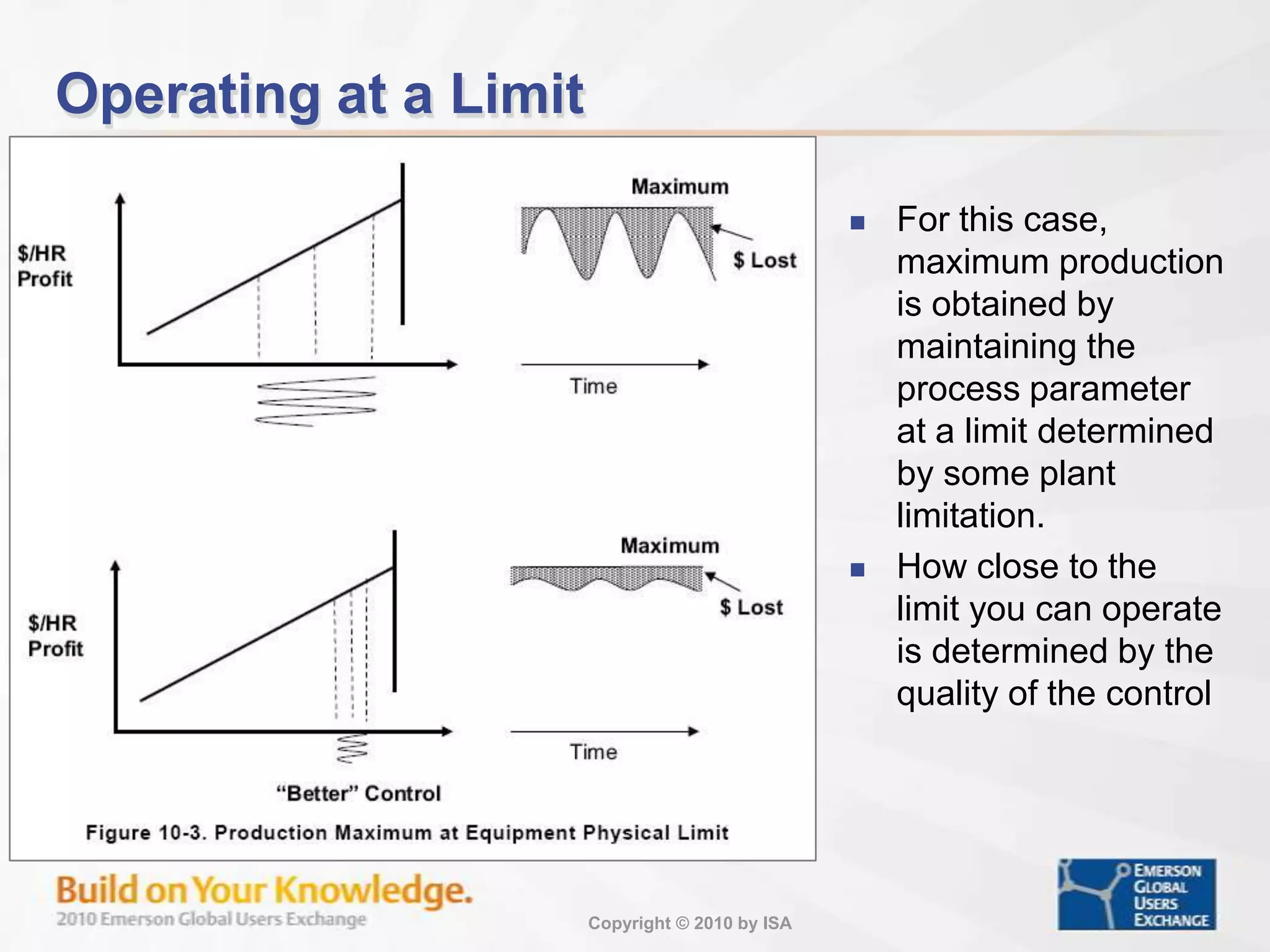
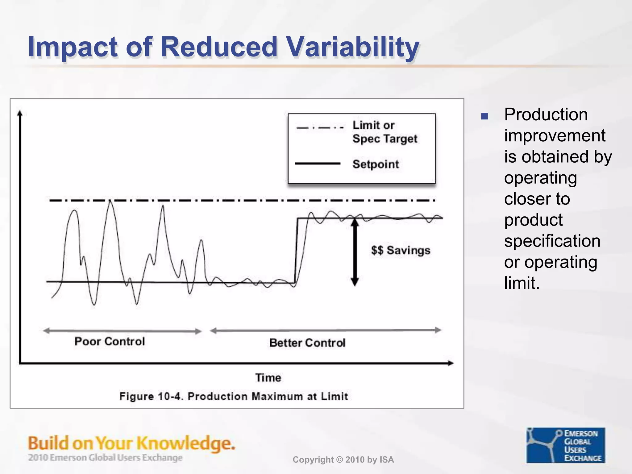
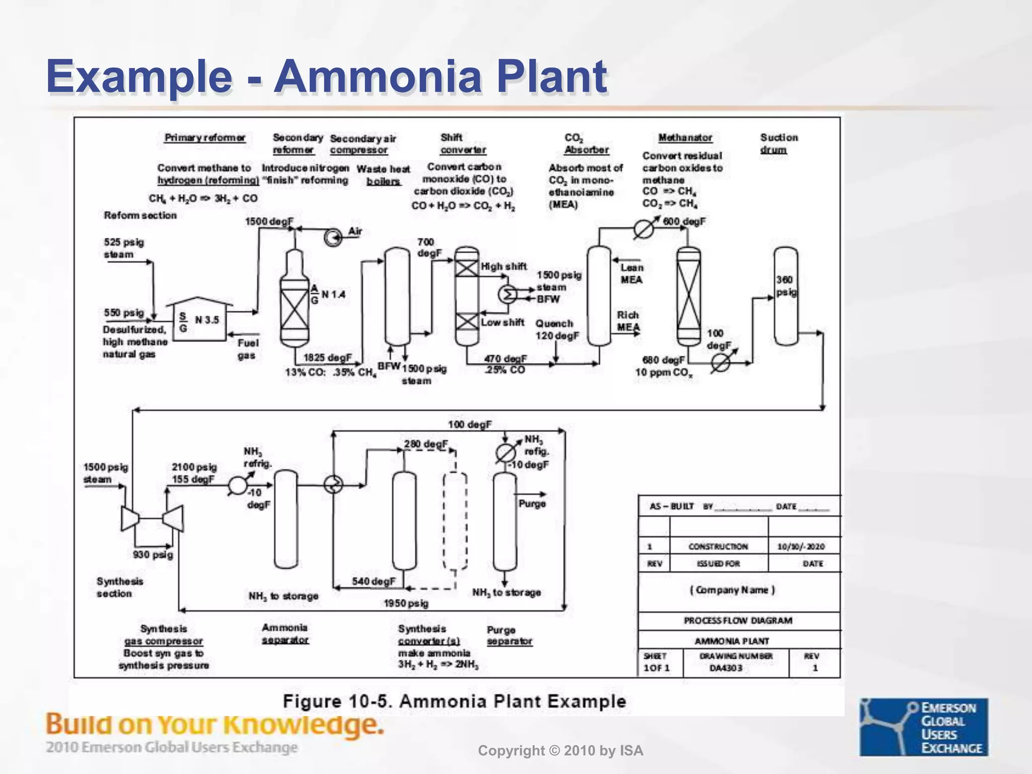
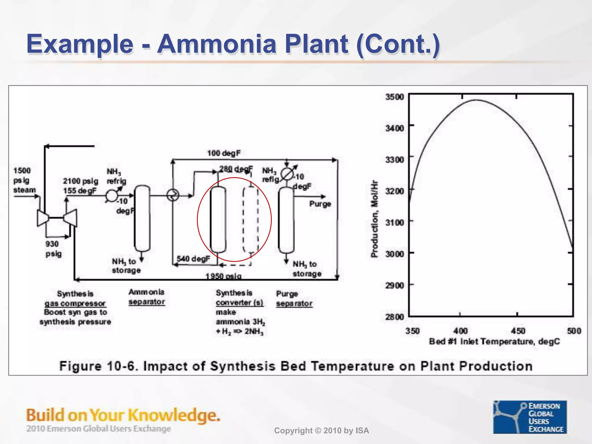
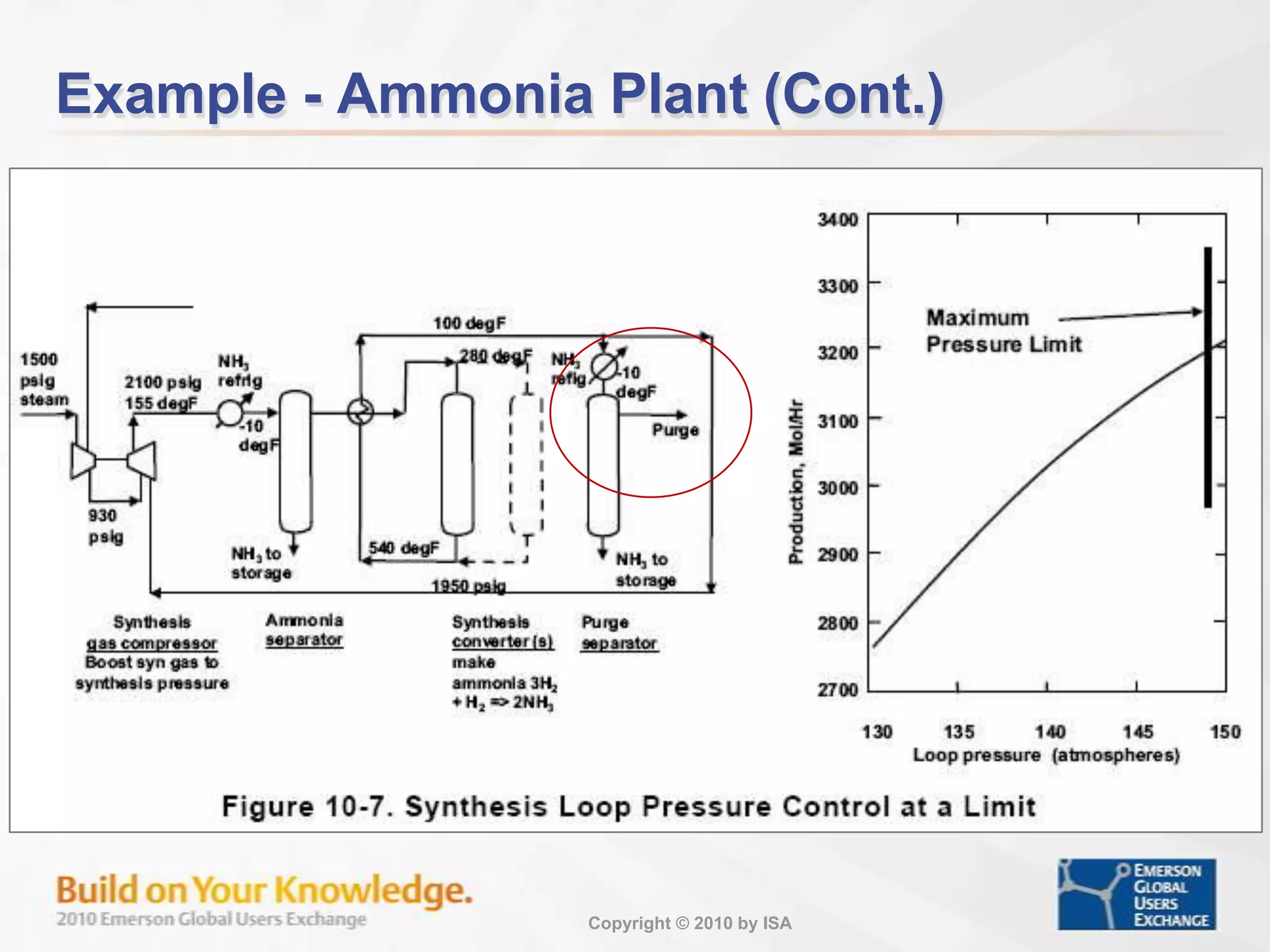
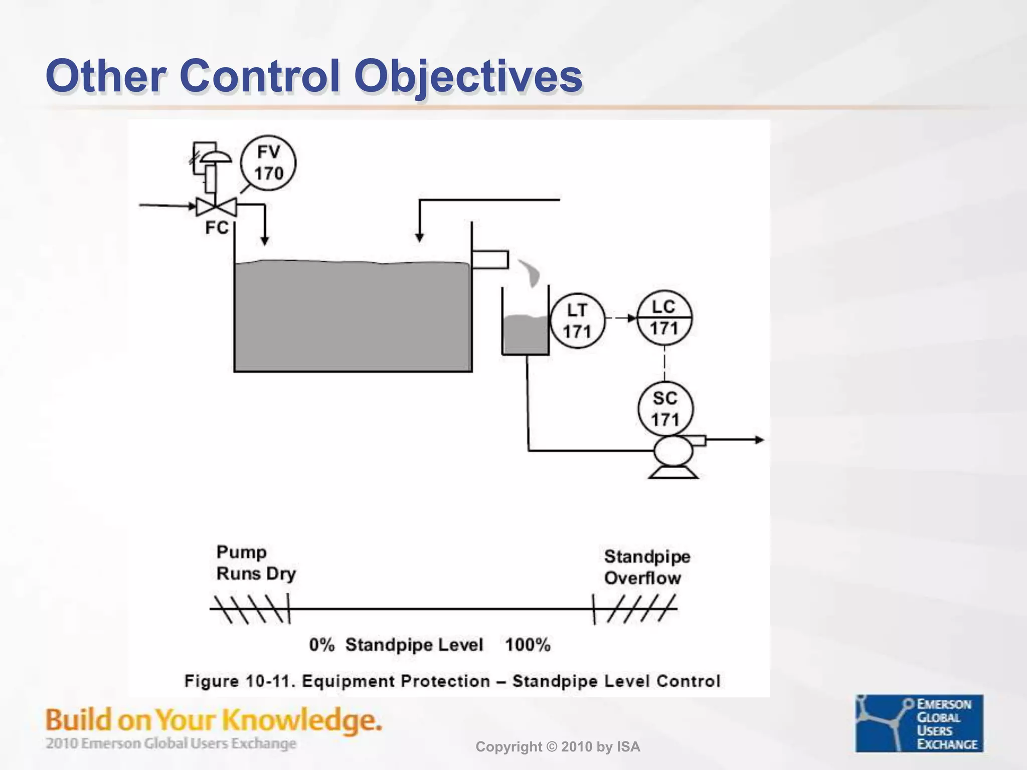
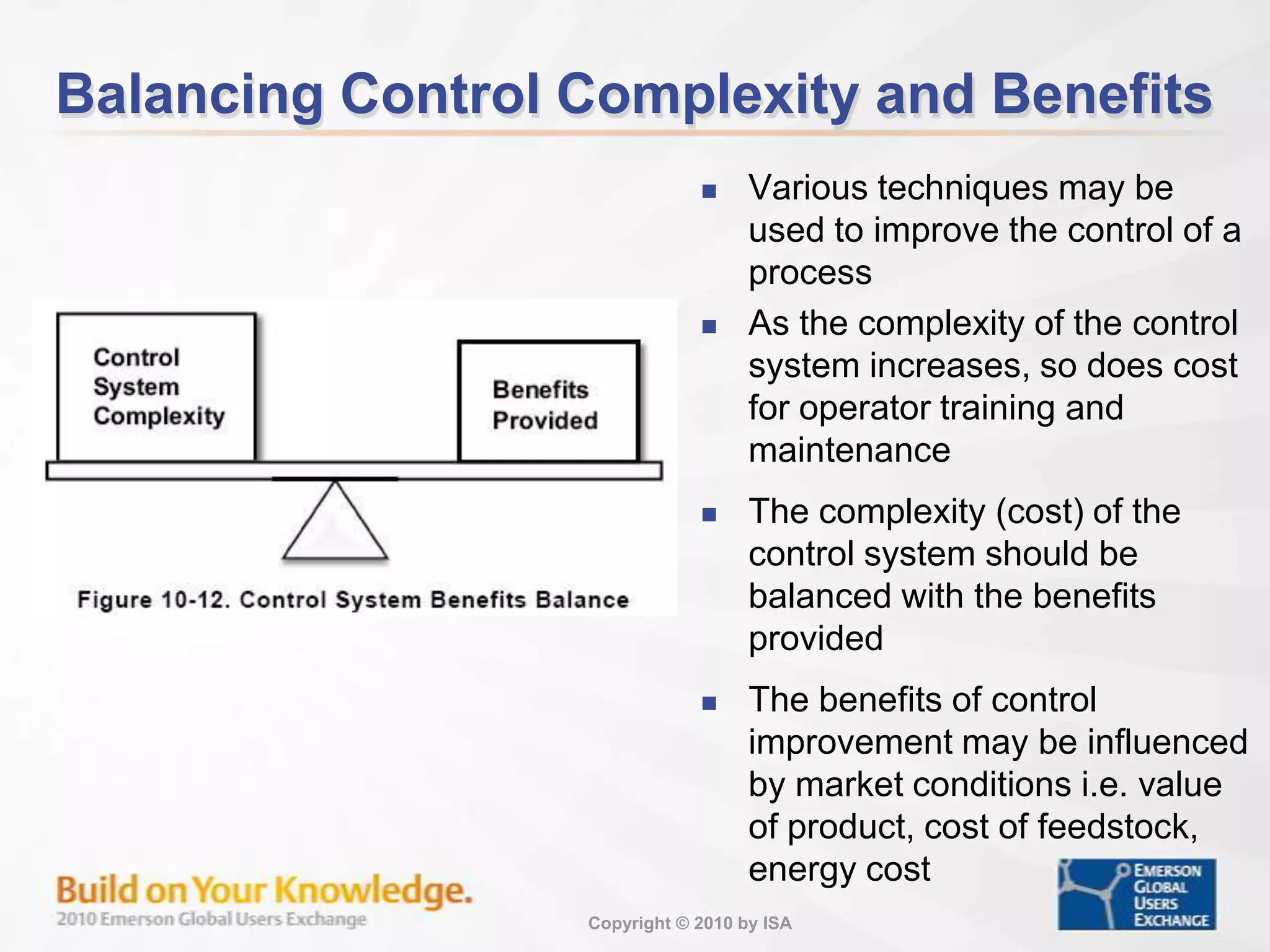
Control objectives focusing on production optimization through variability reduction and operational limits.
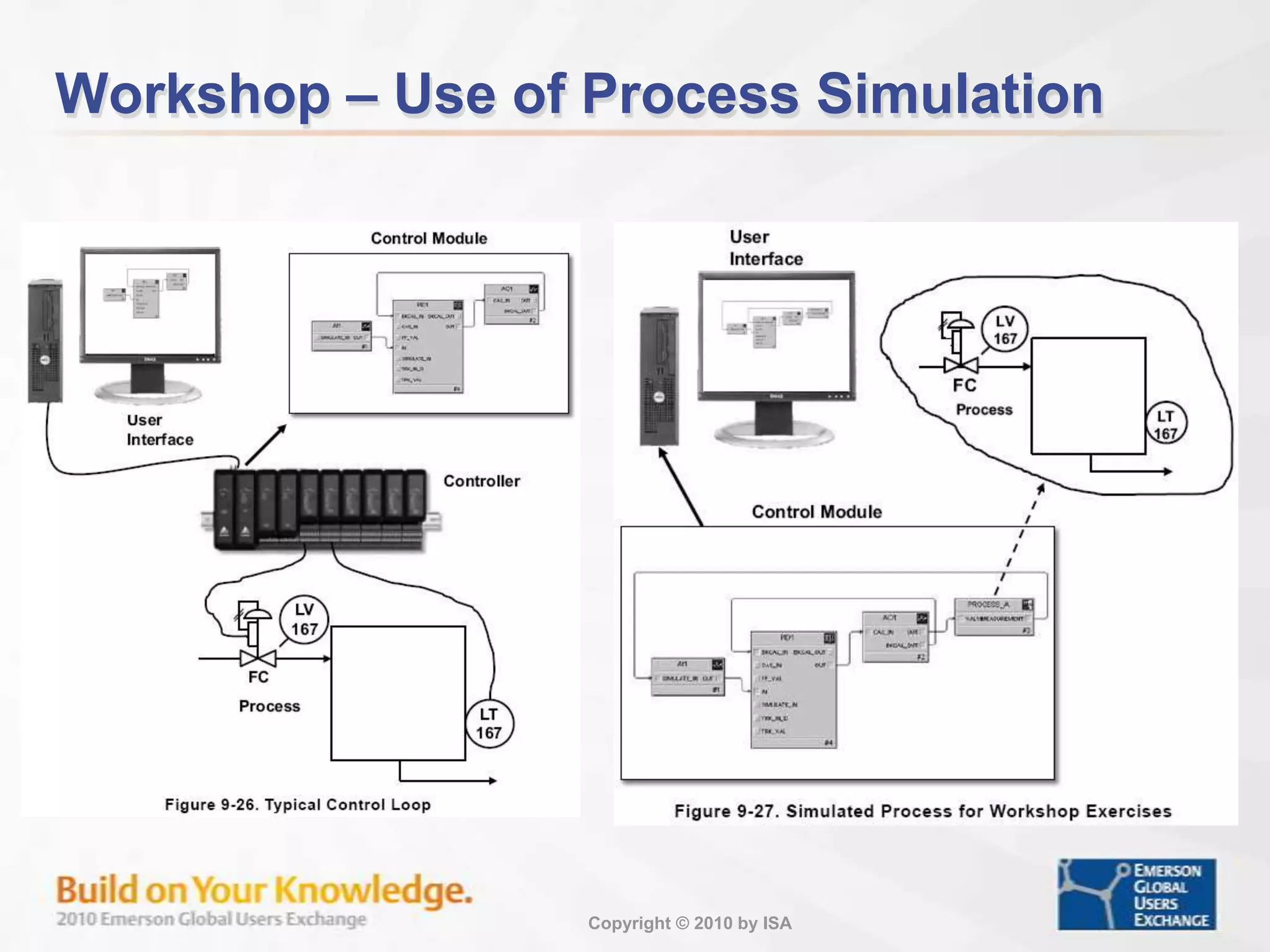
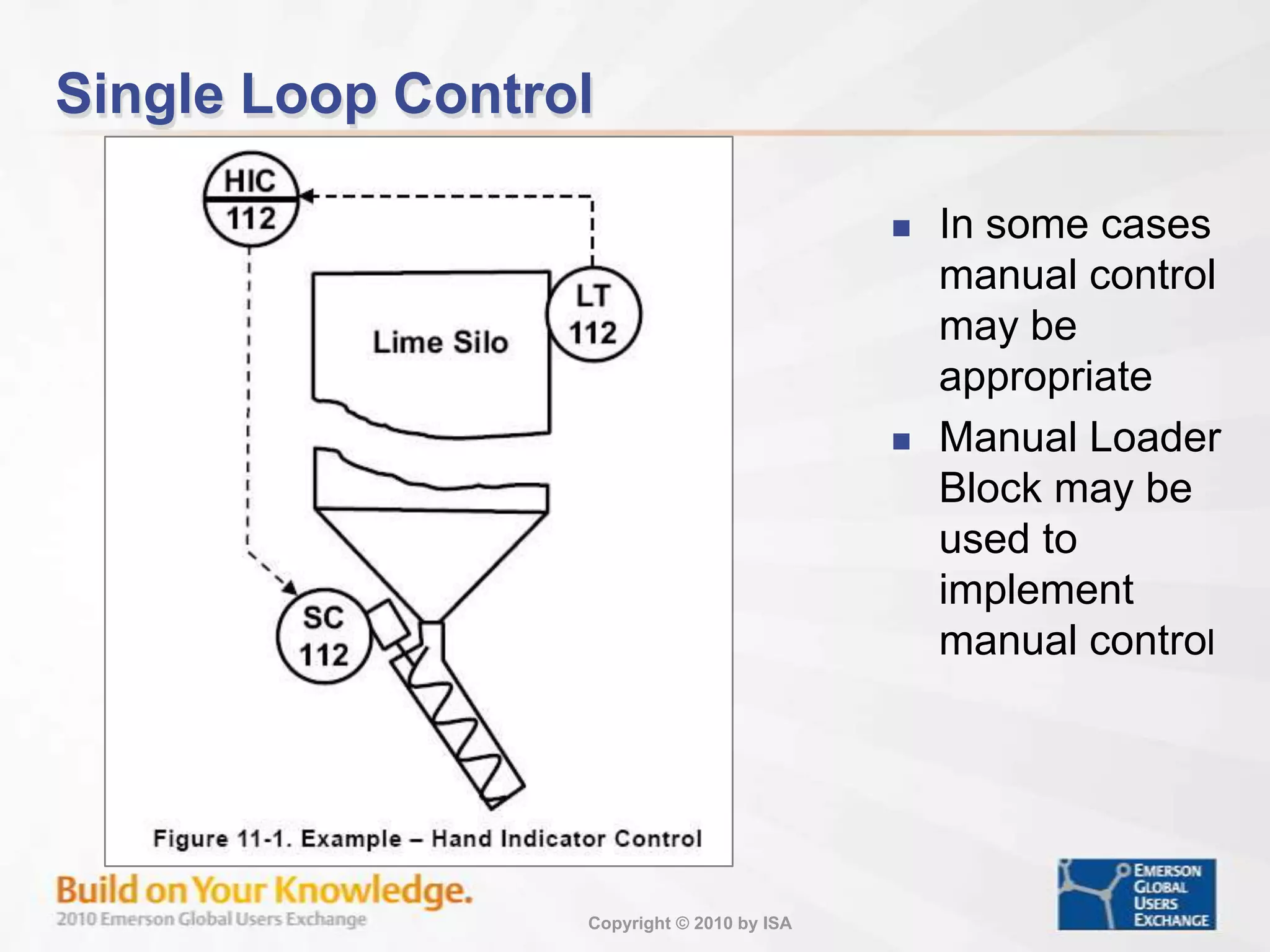
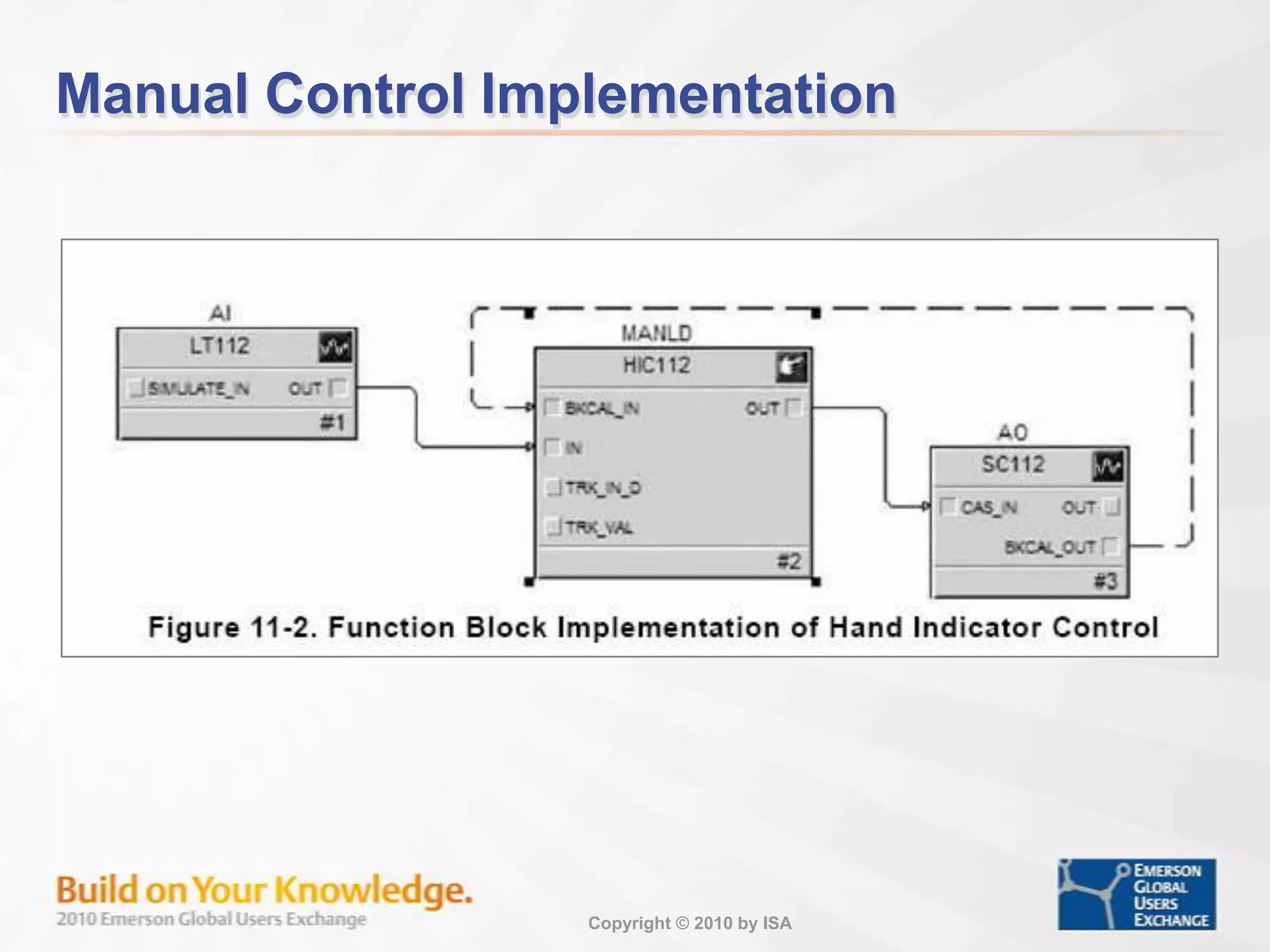
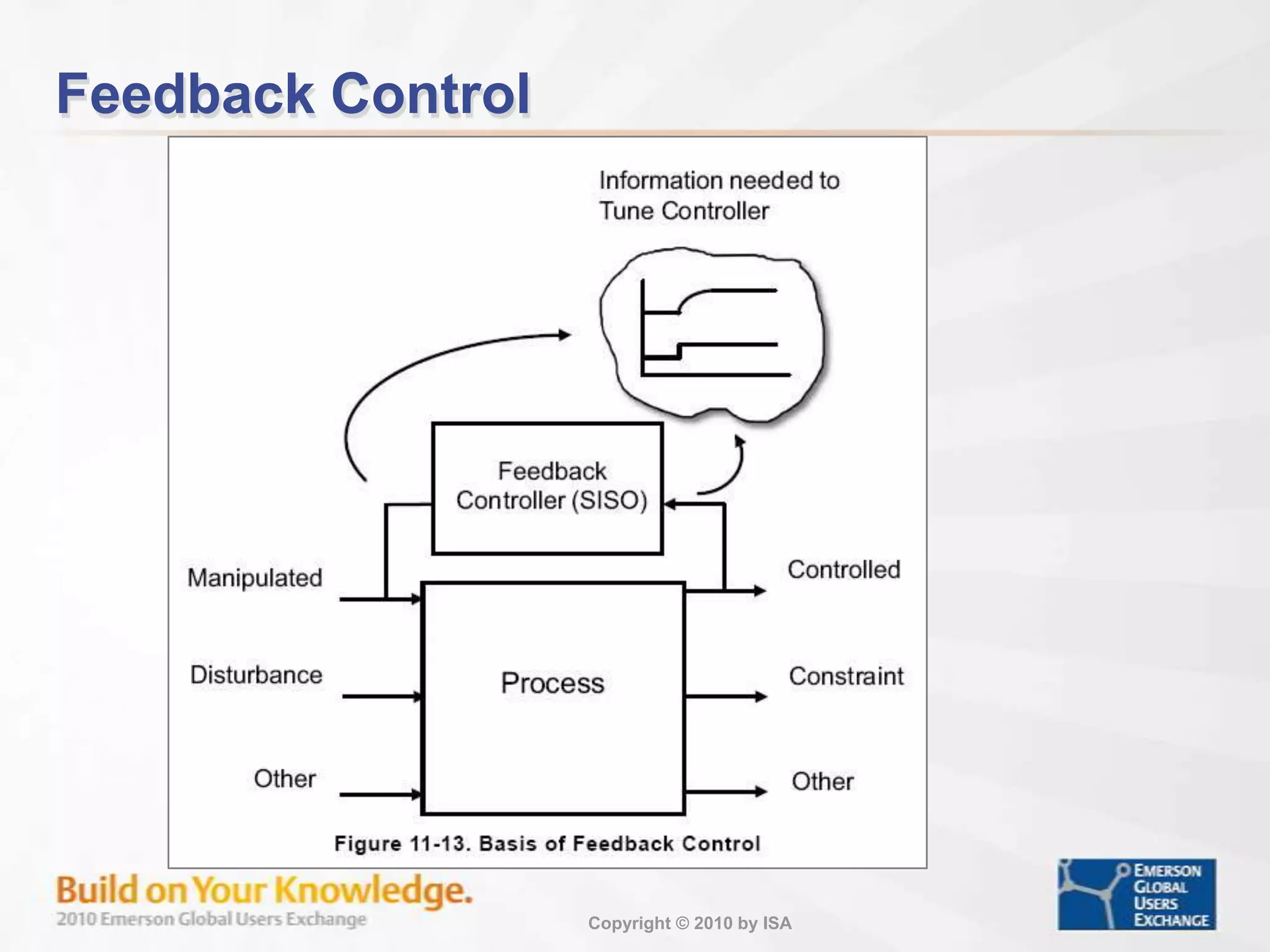
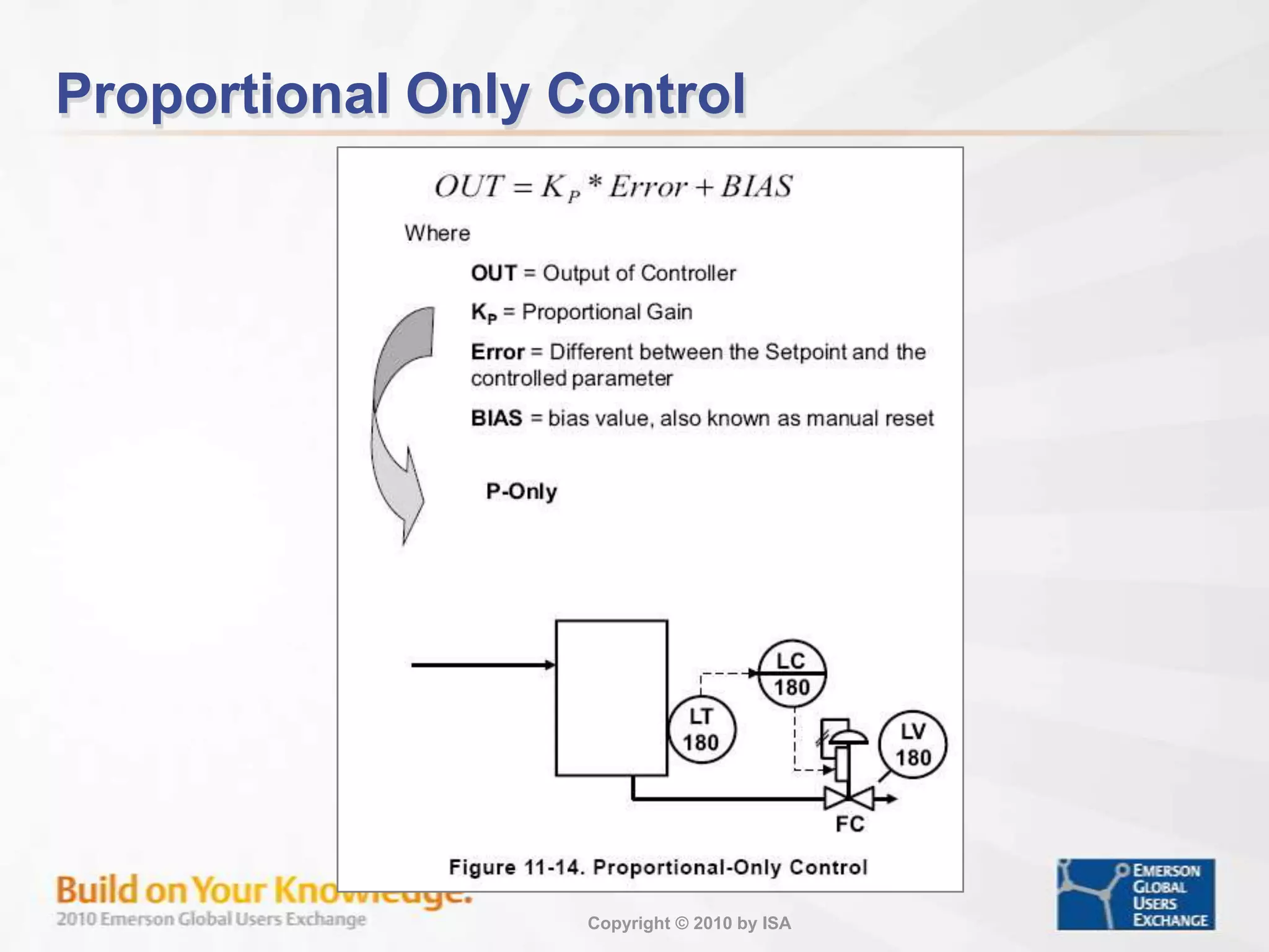
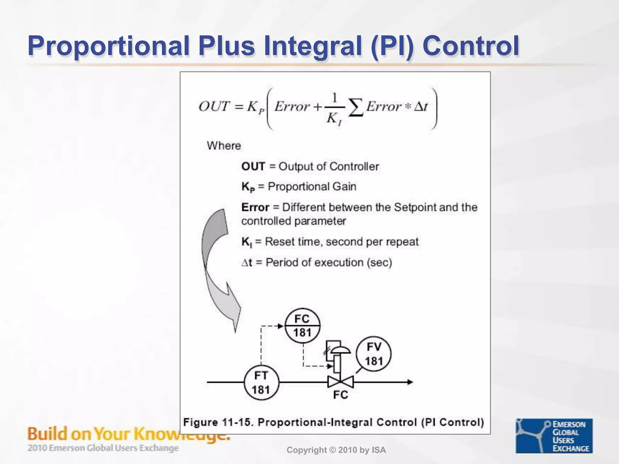
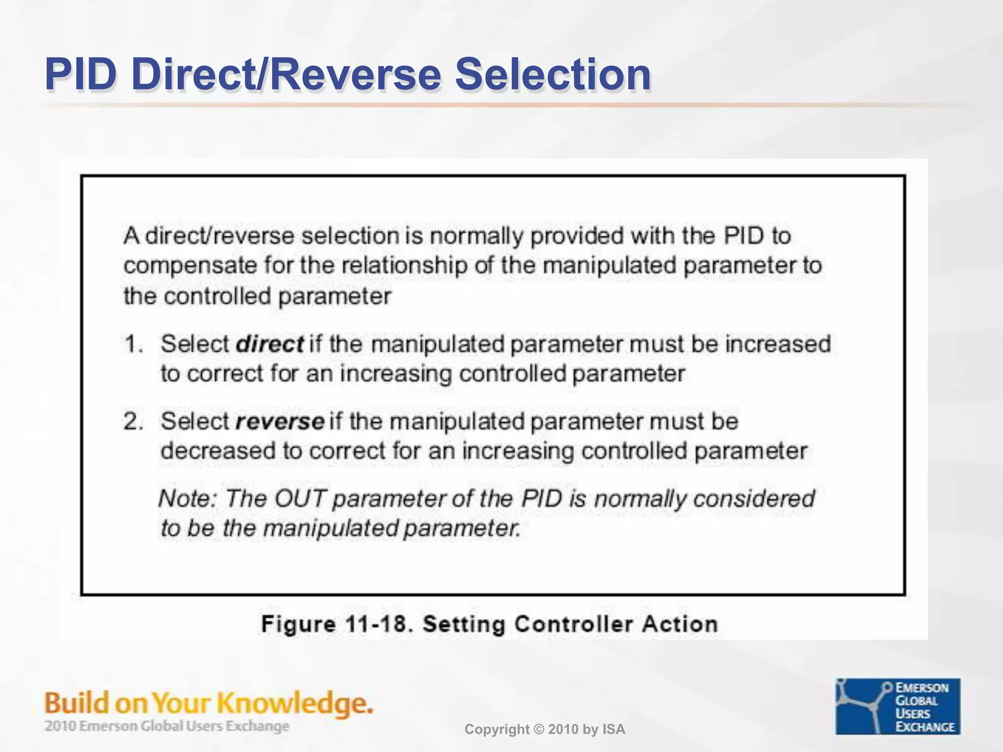
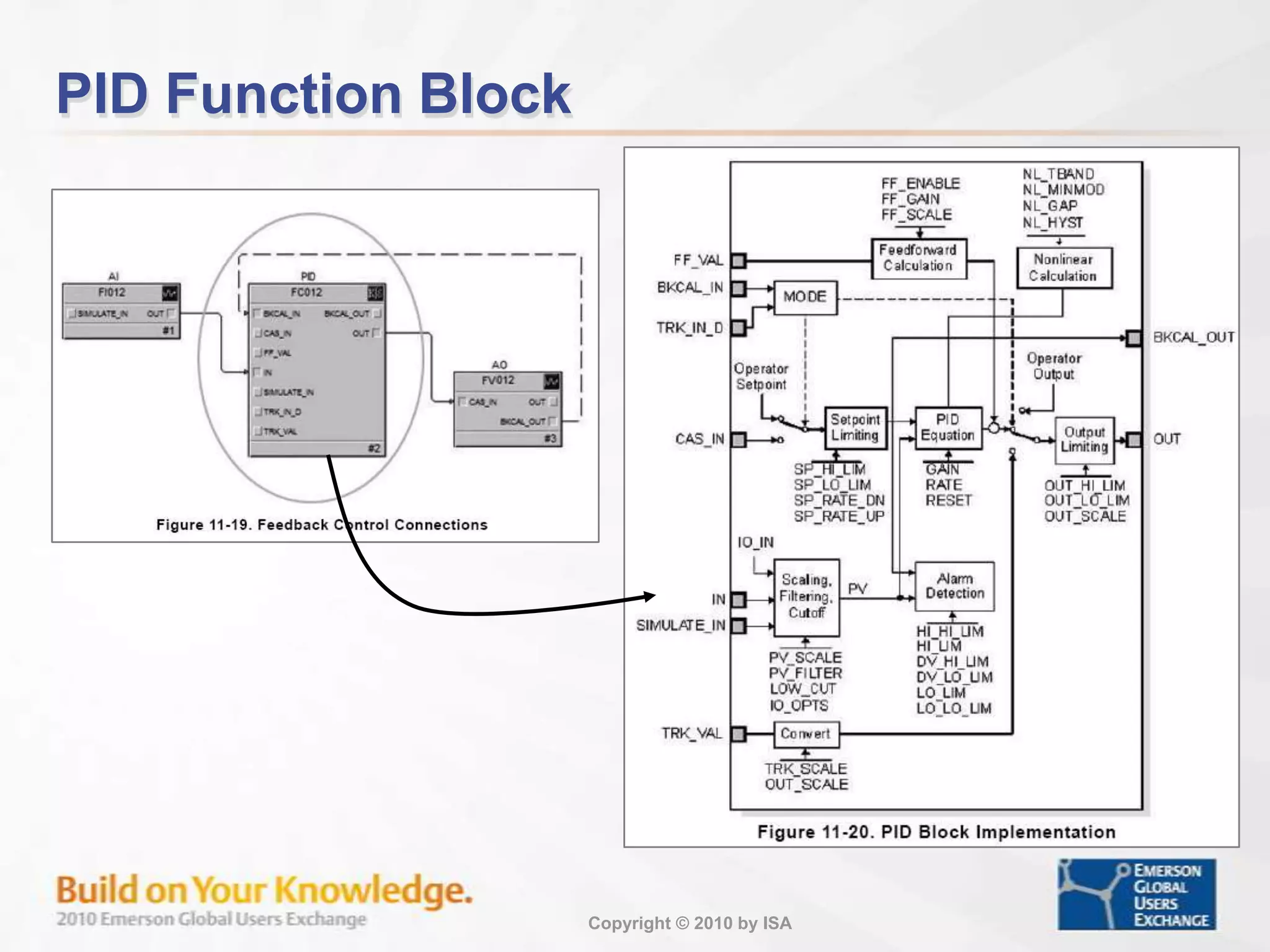
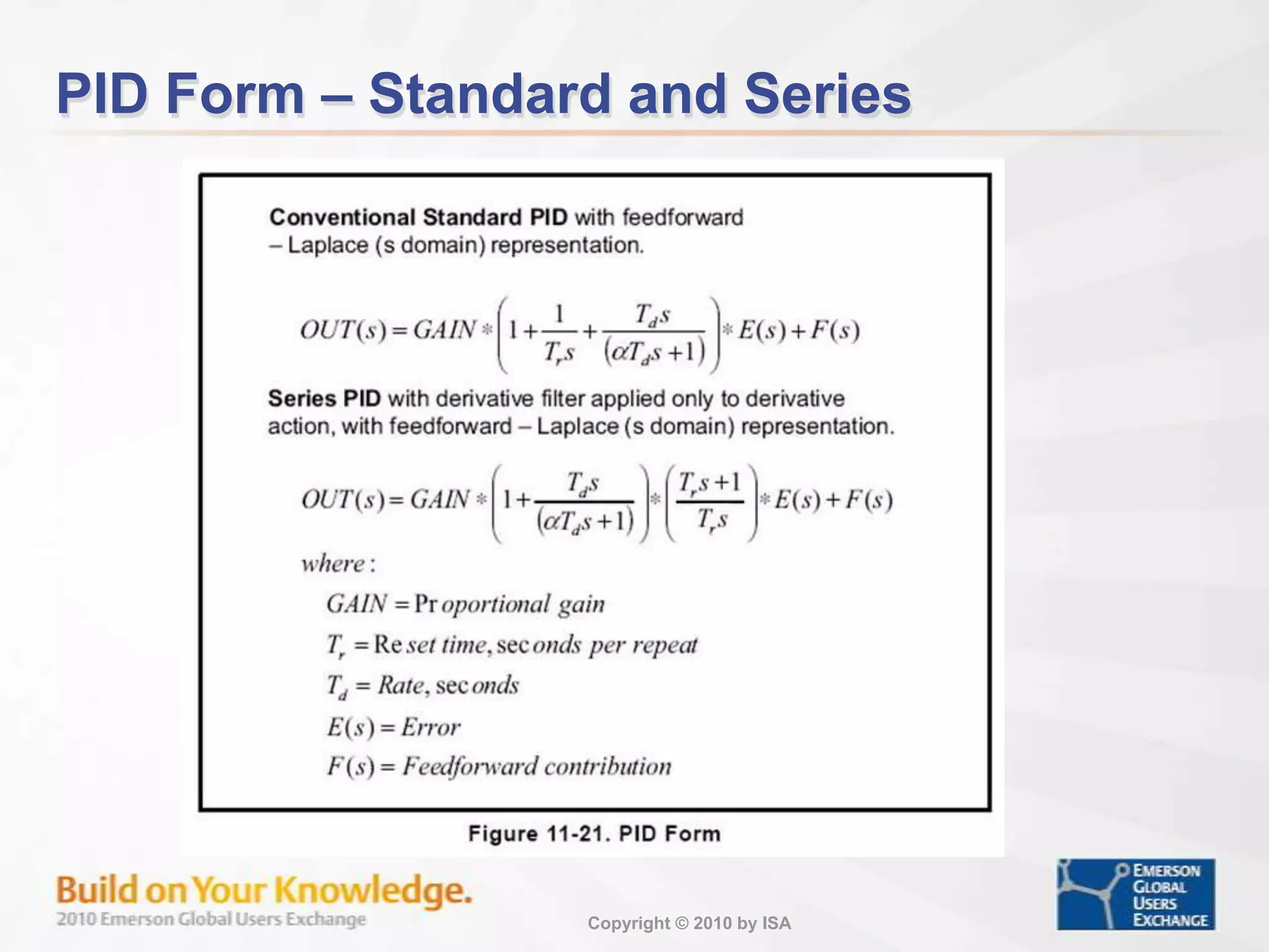
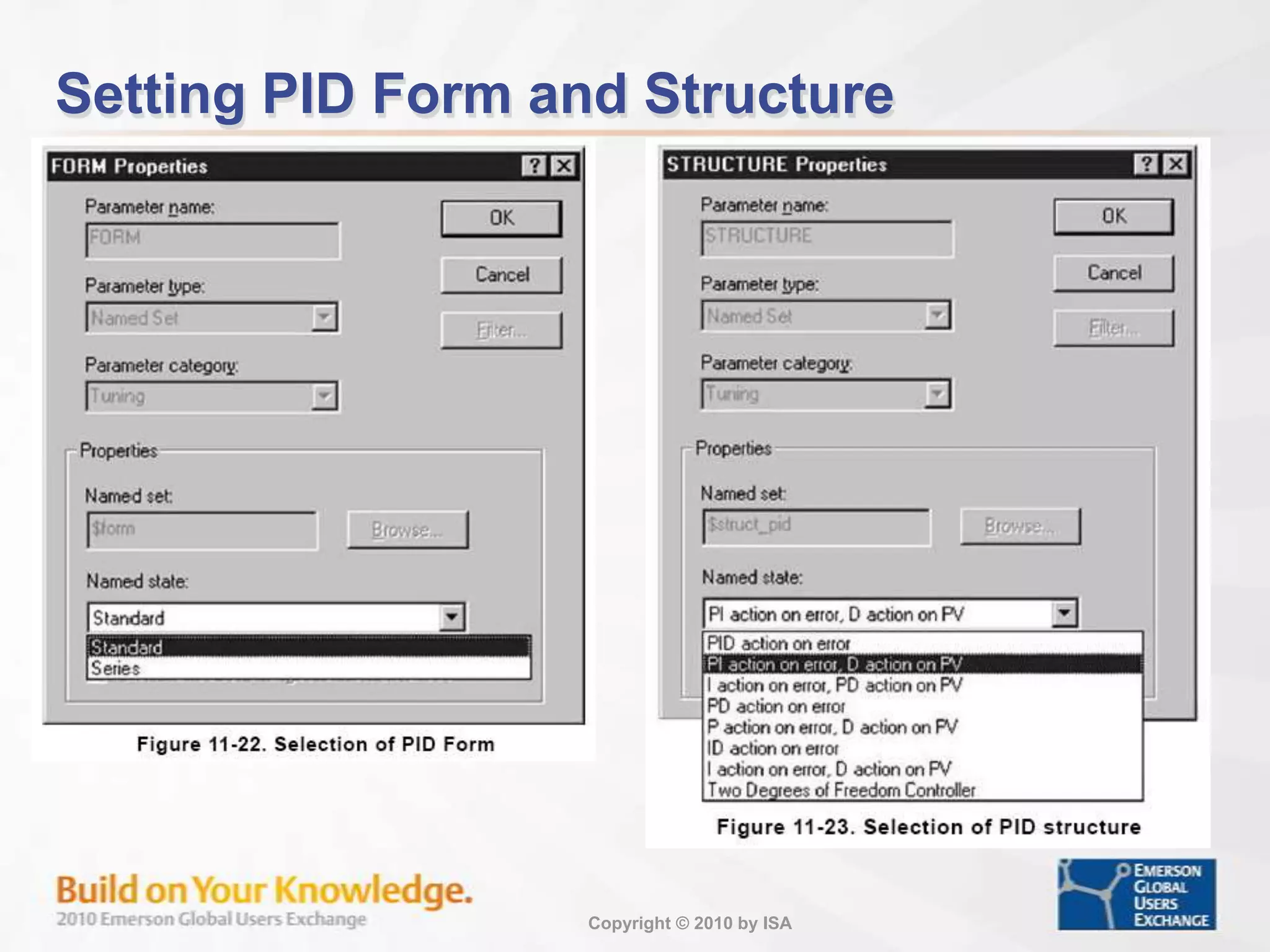
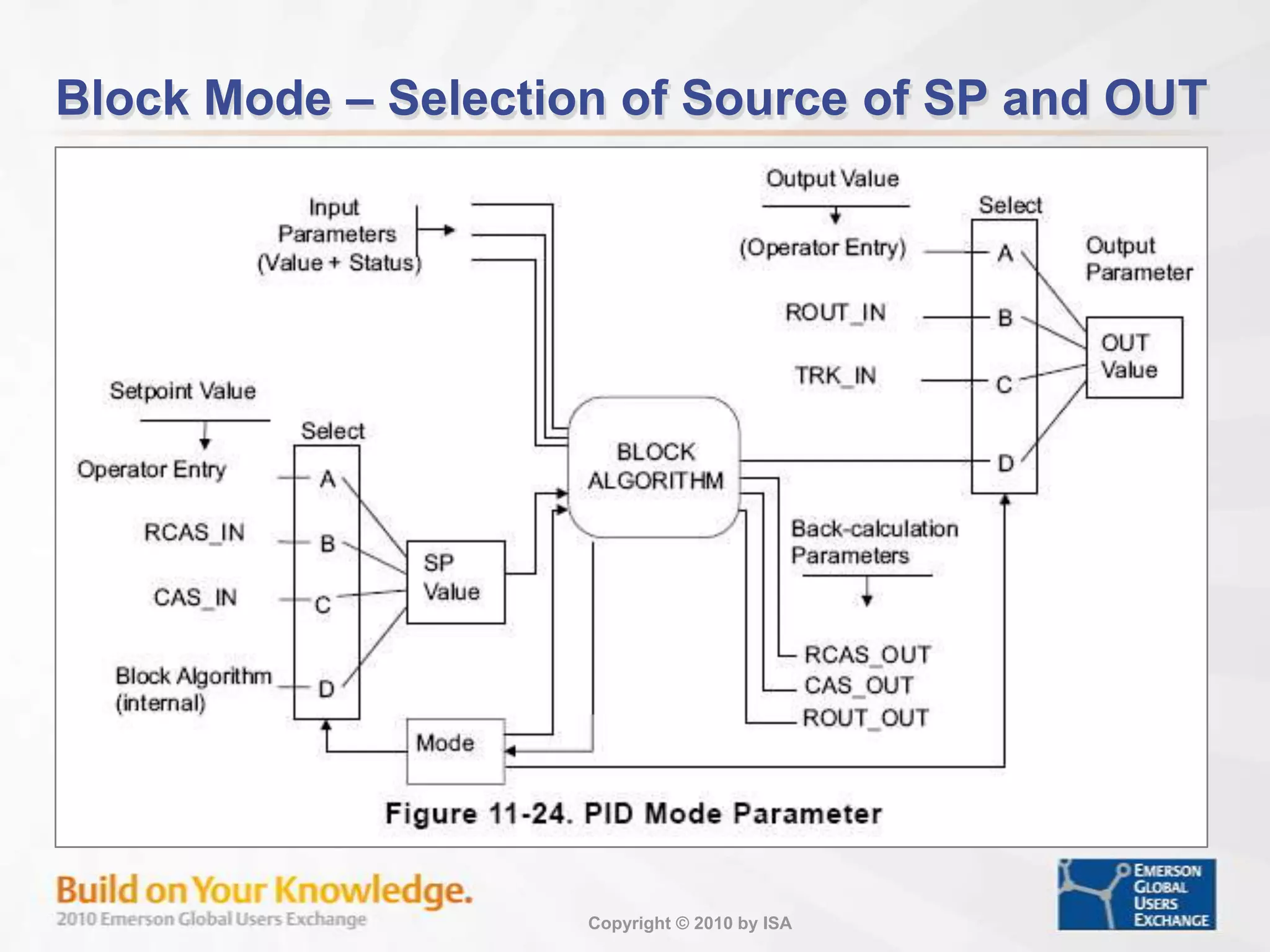
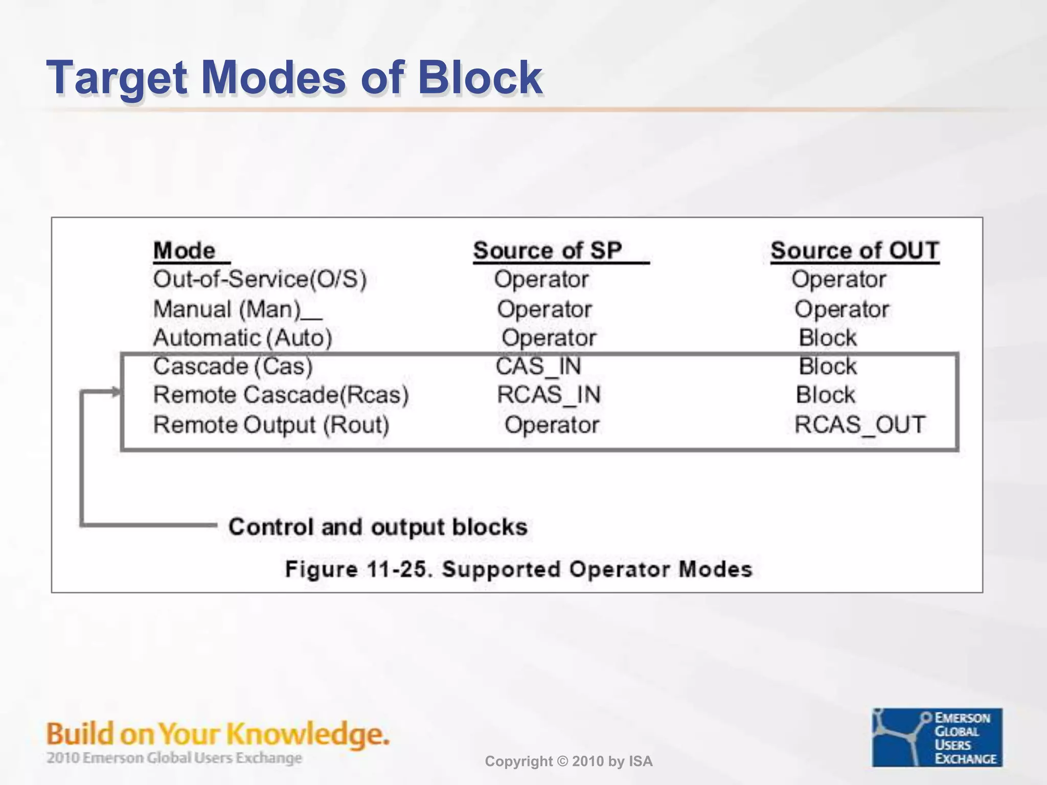
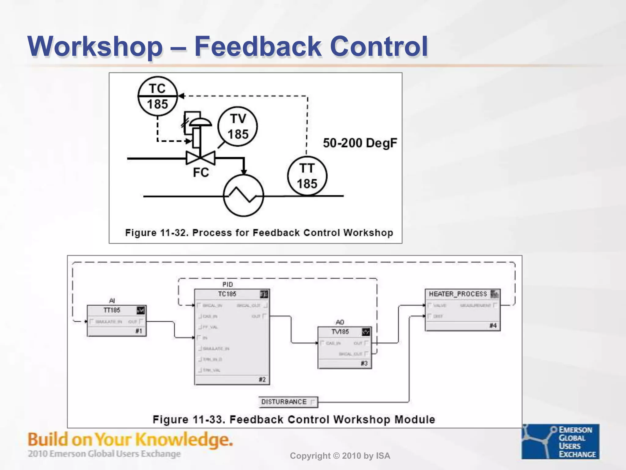
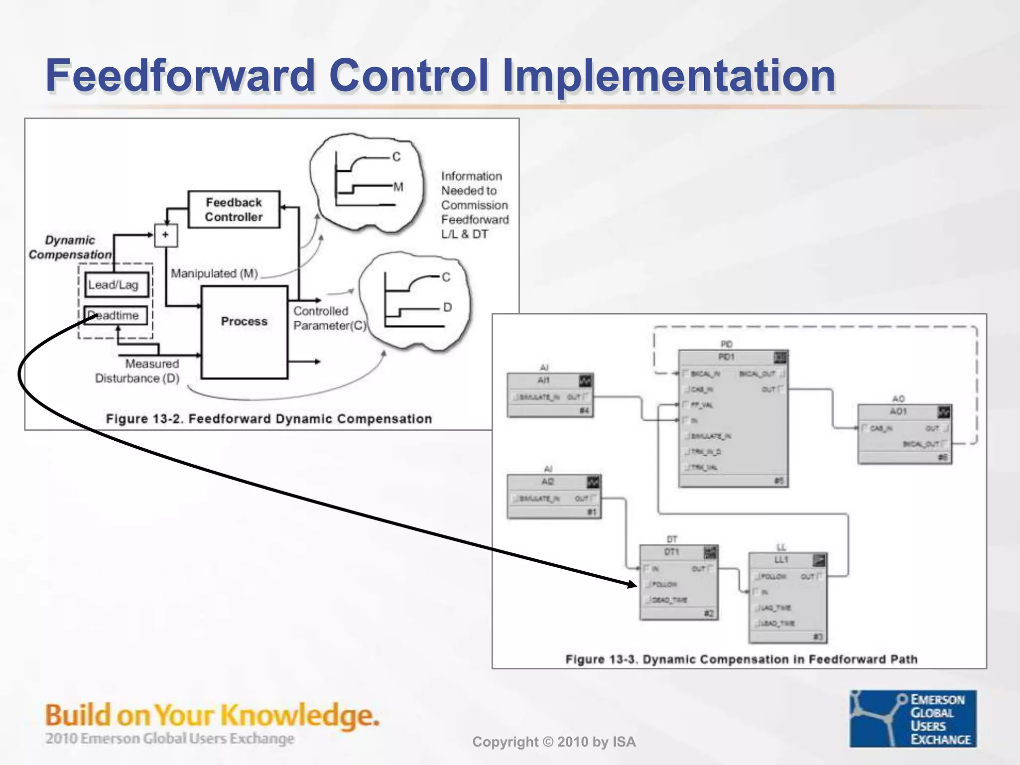
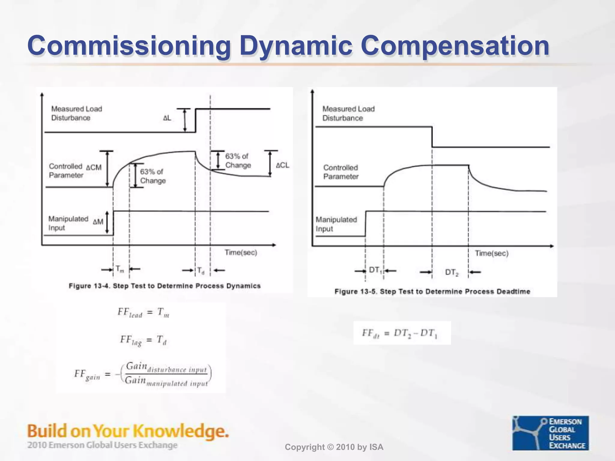
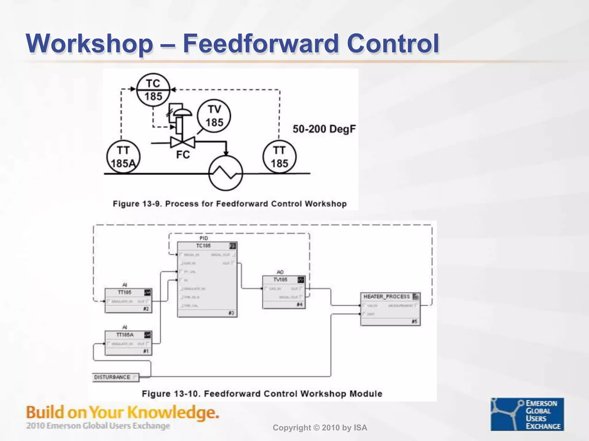
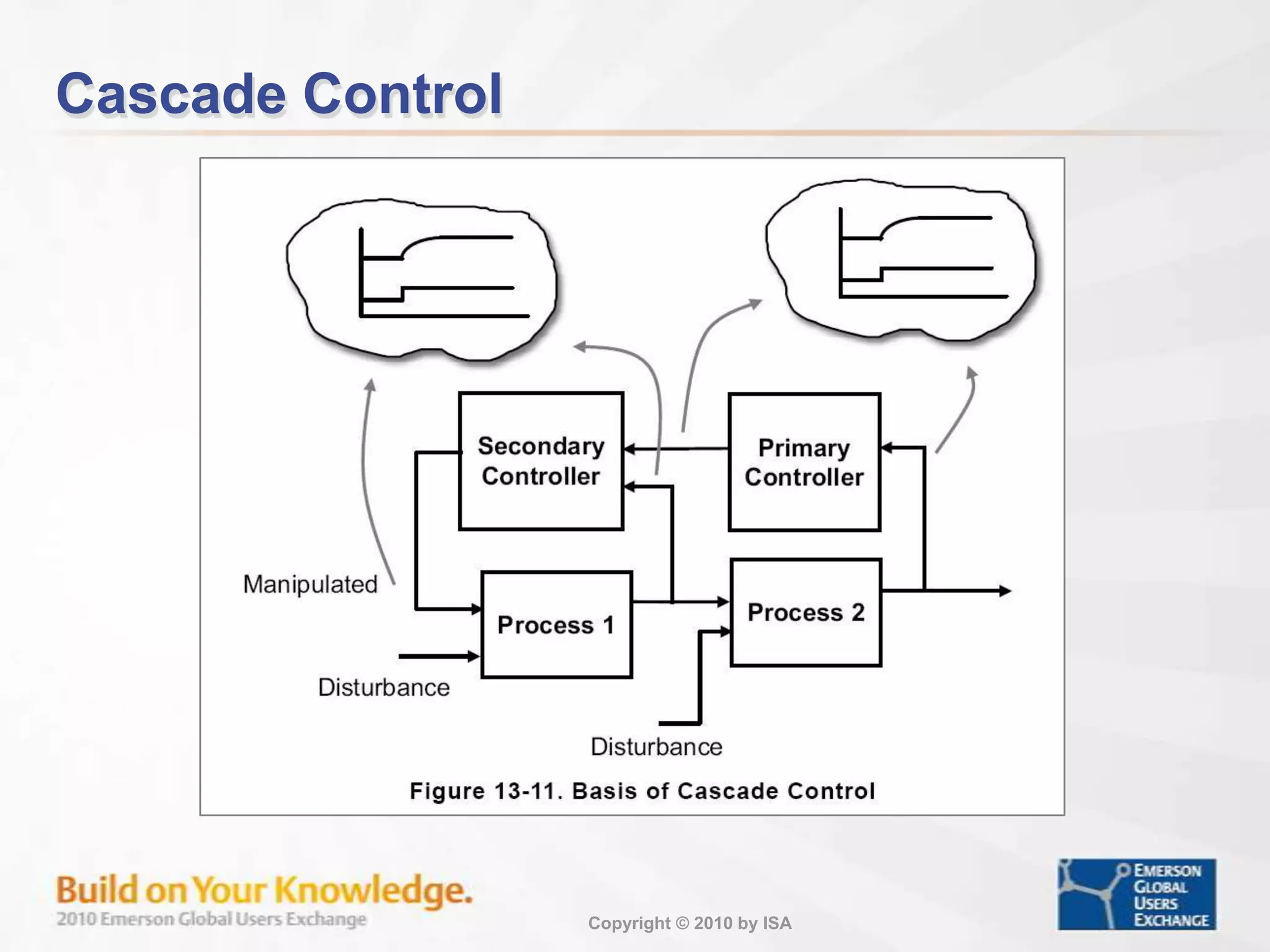
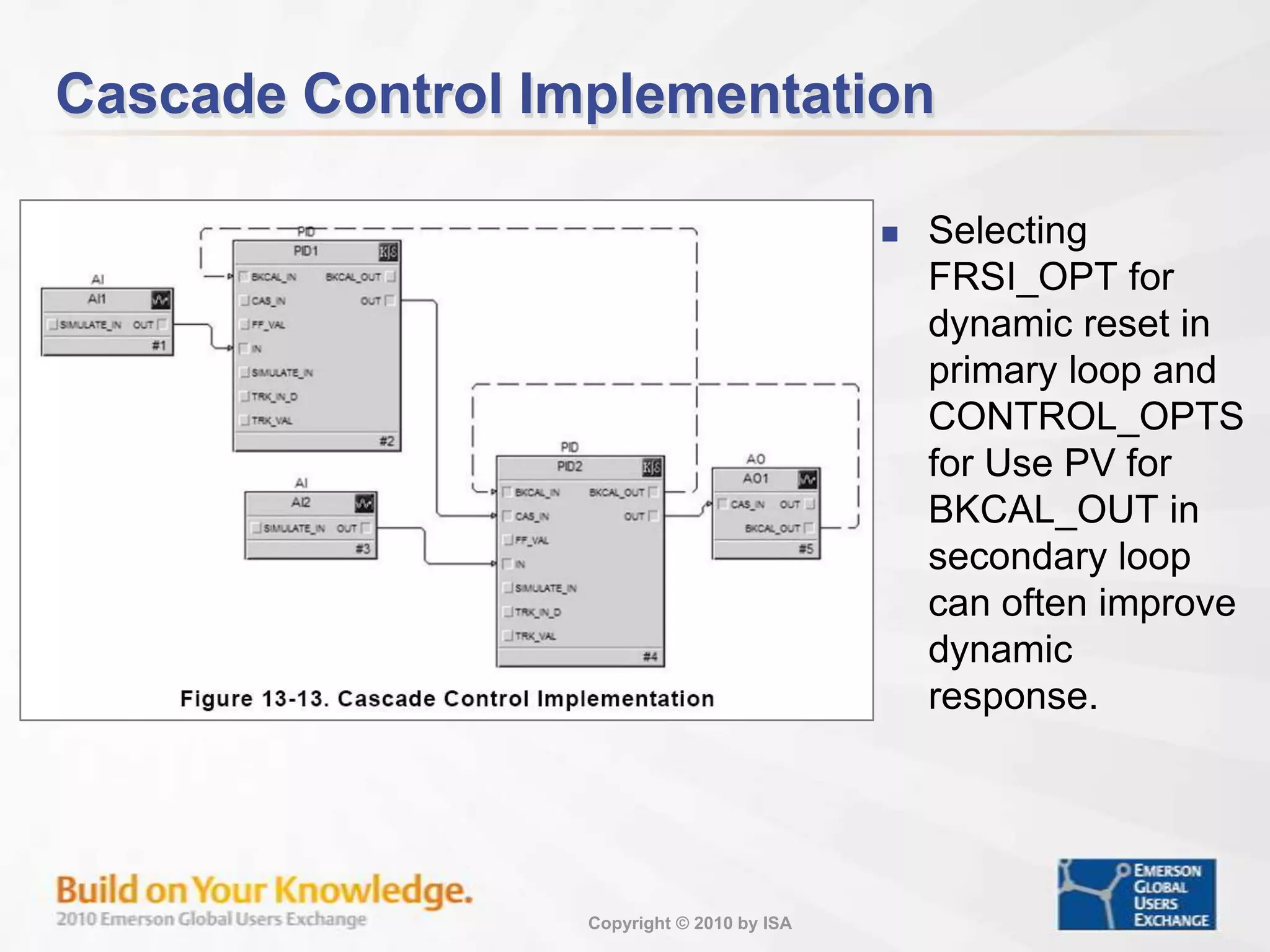
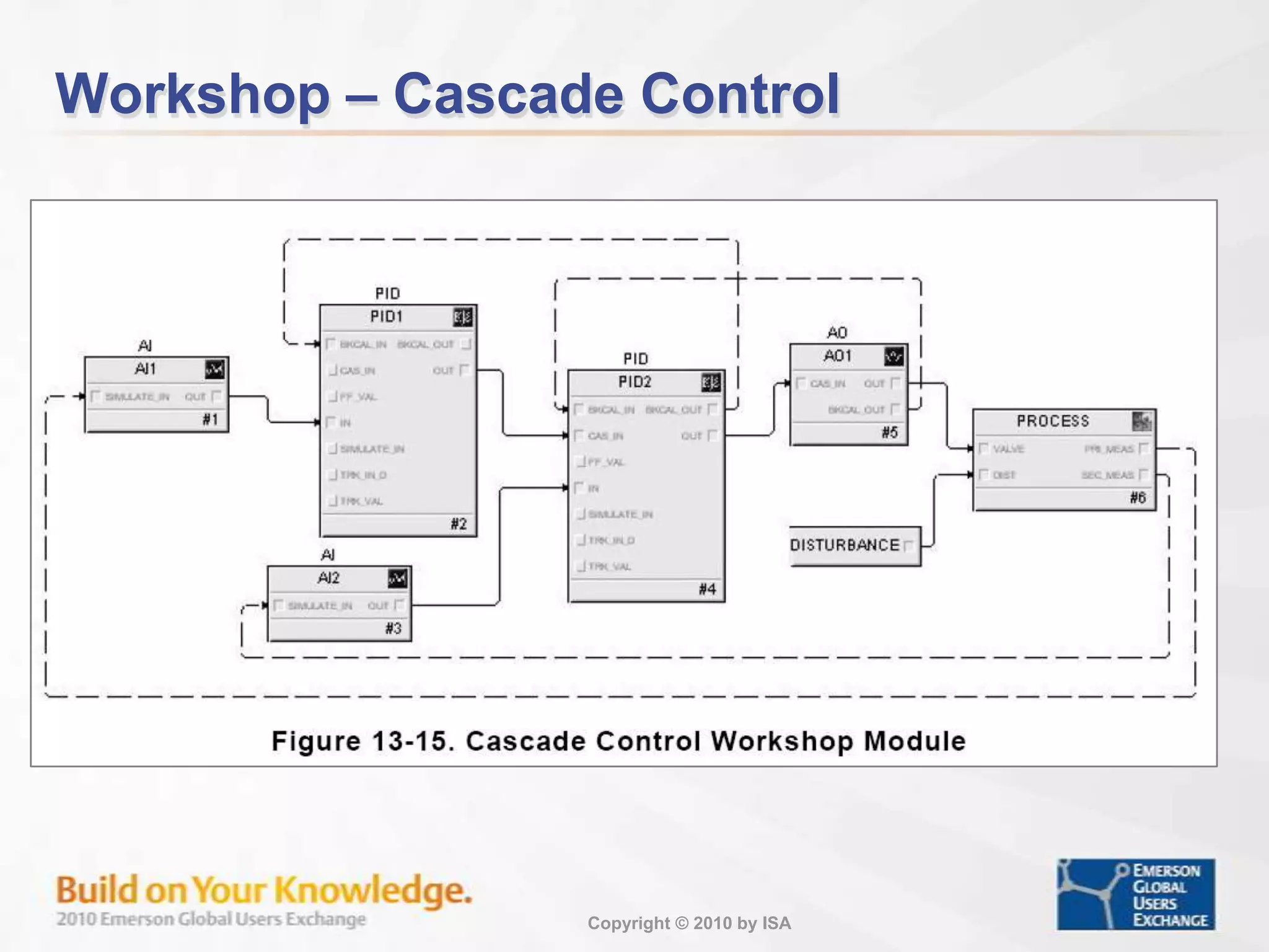
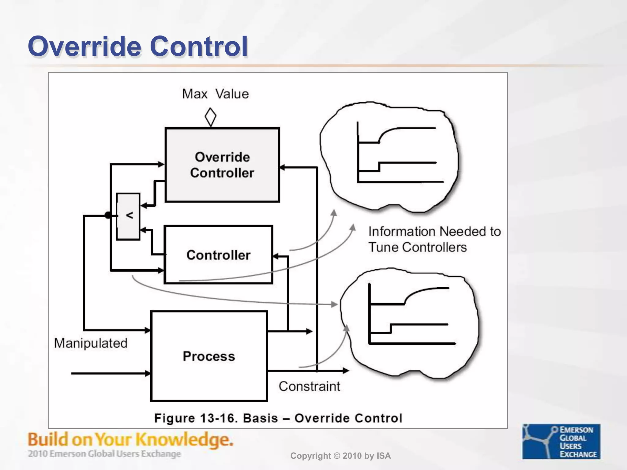
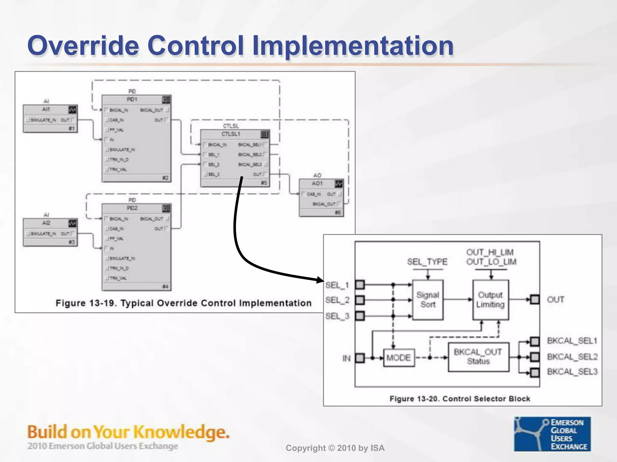
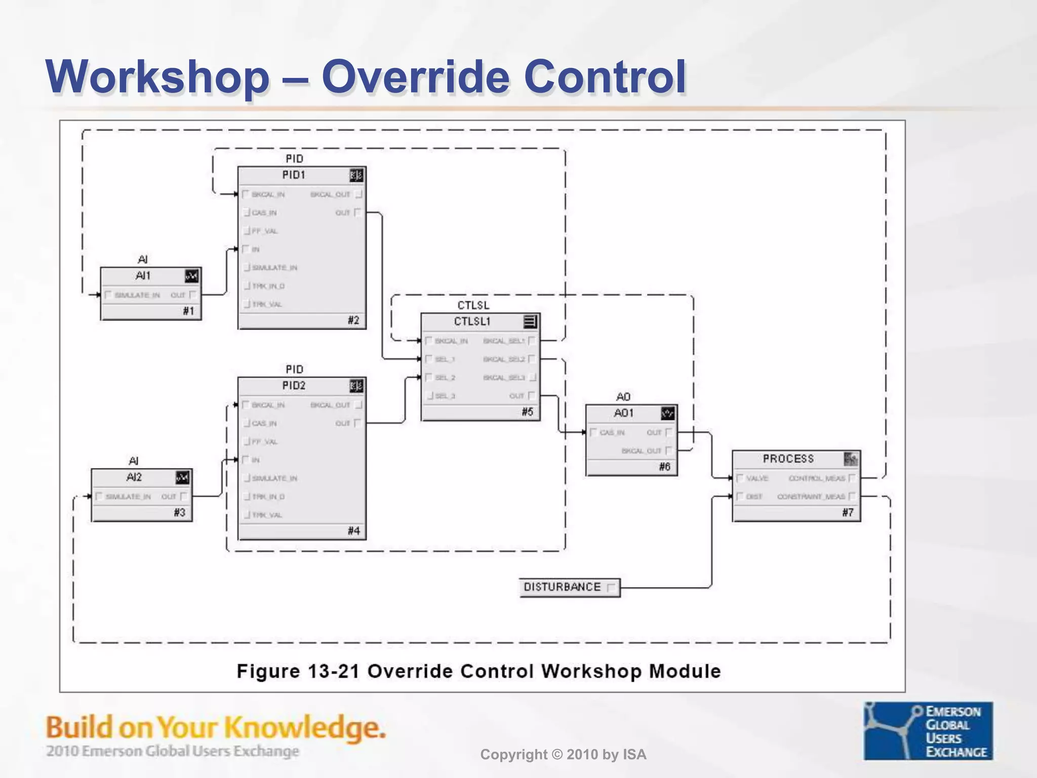
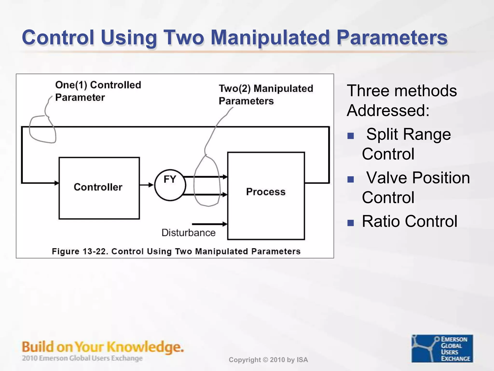
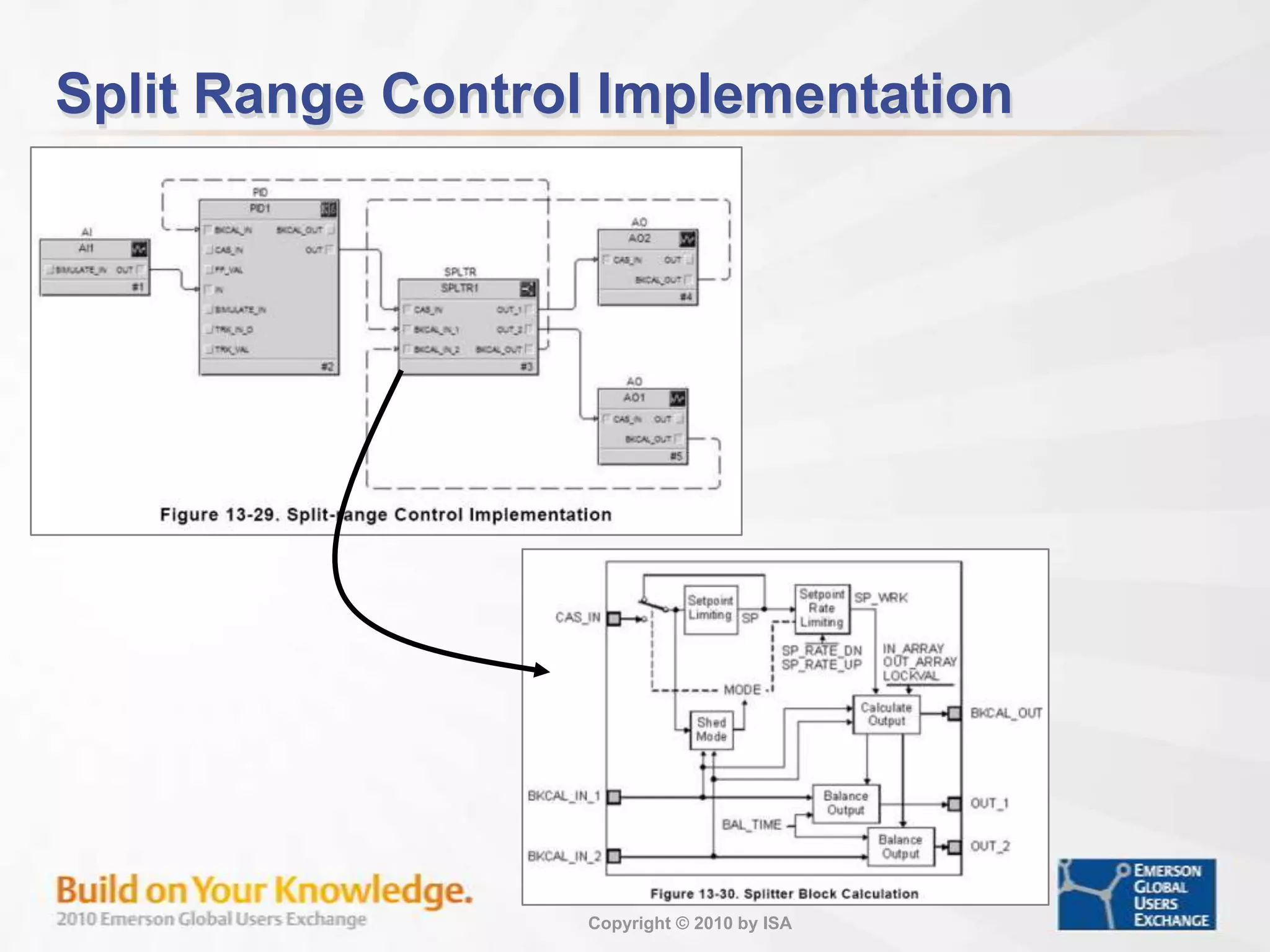
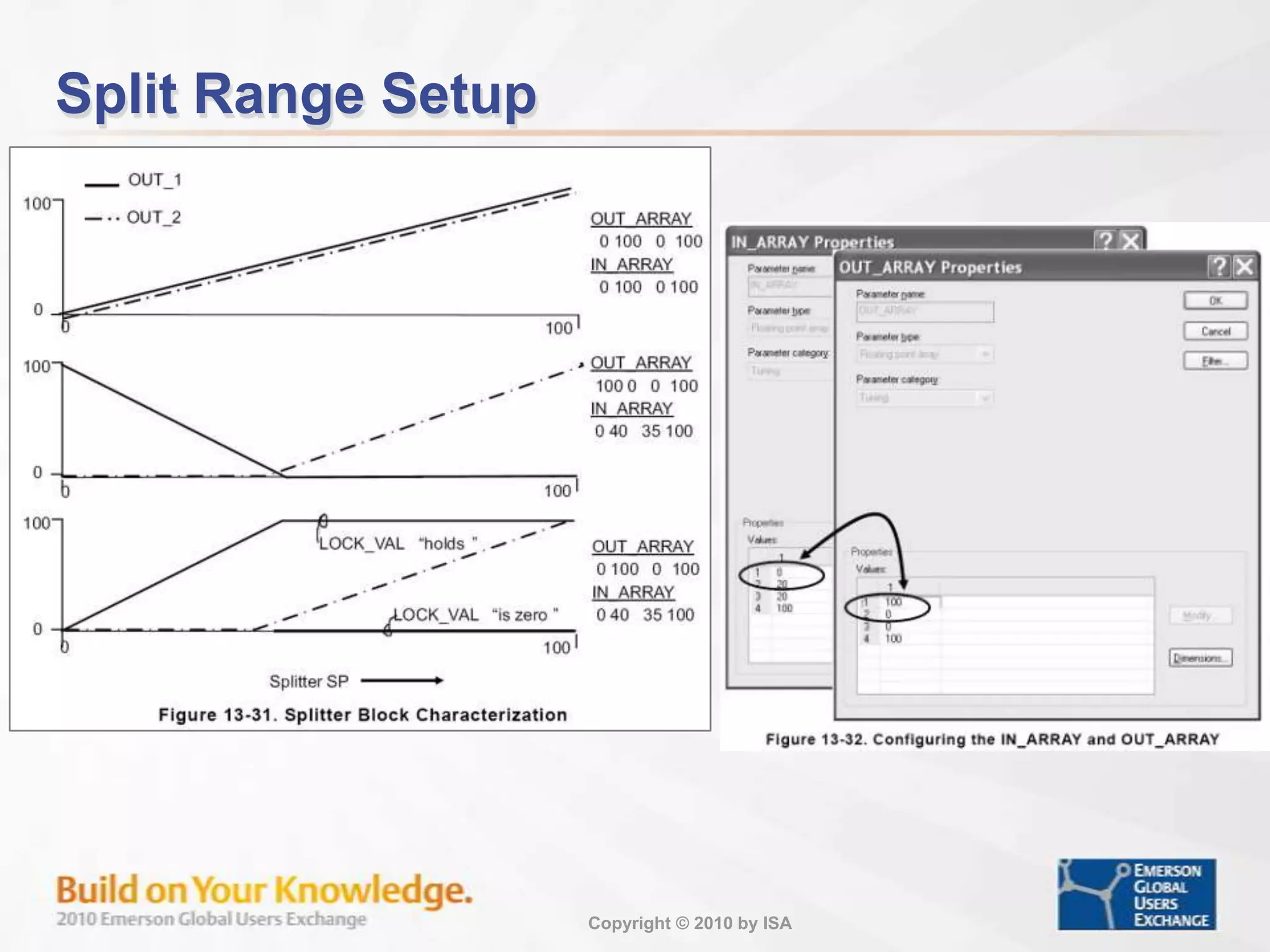
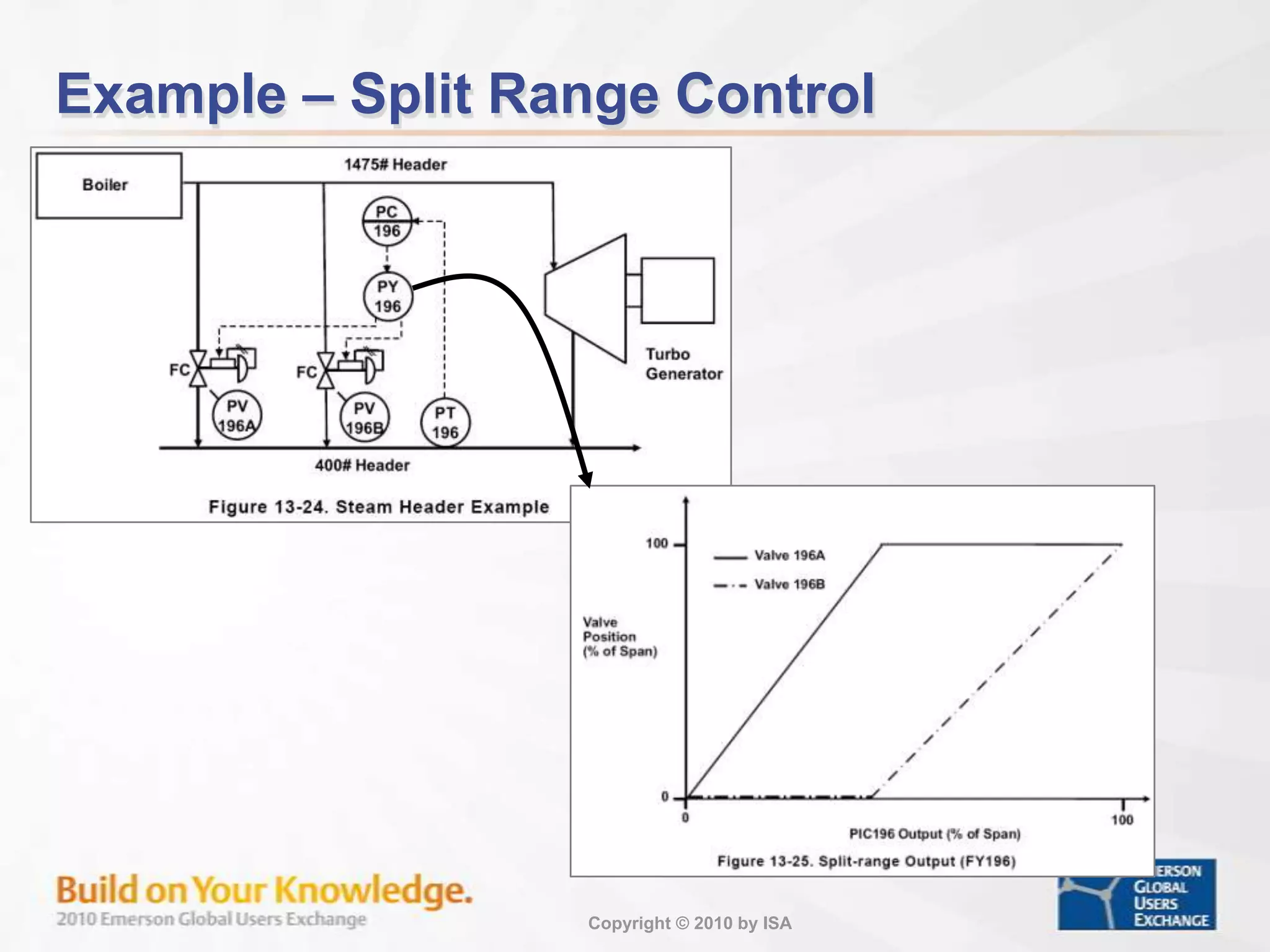
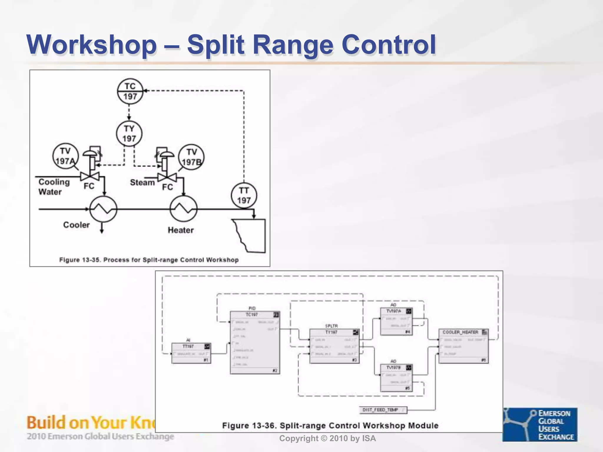
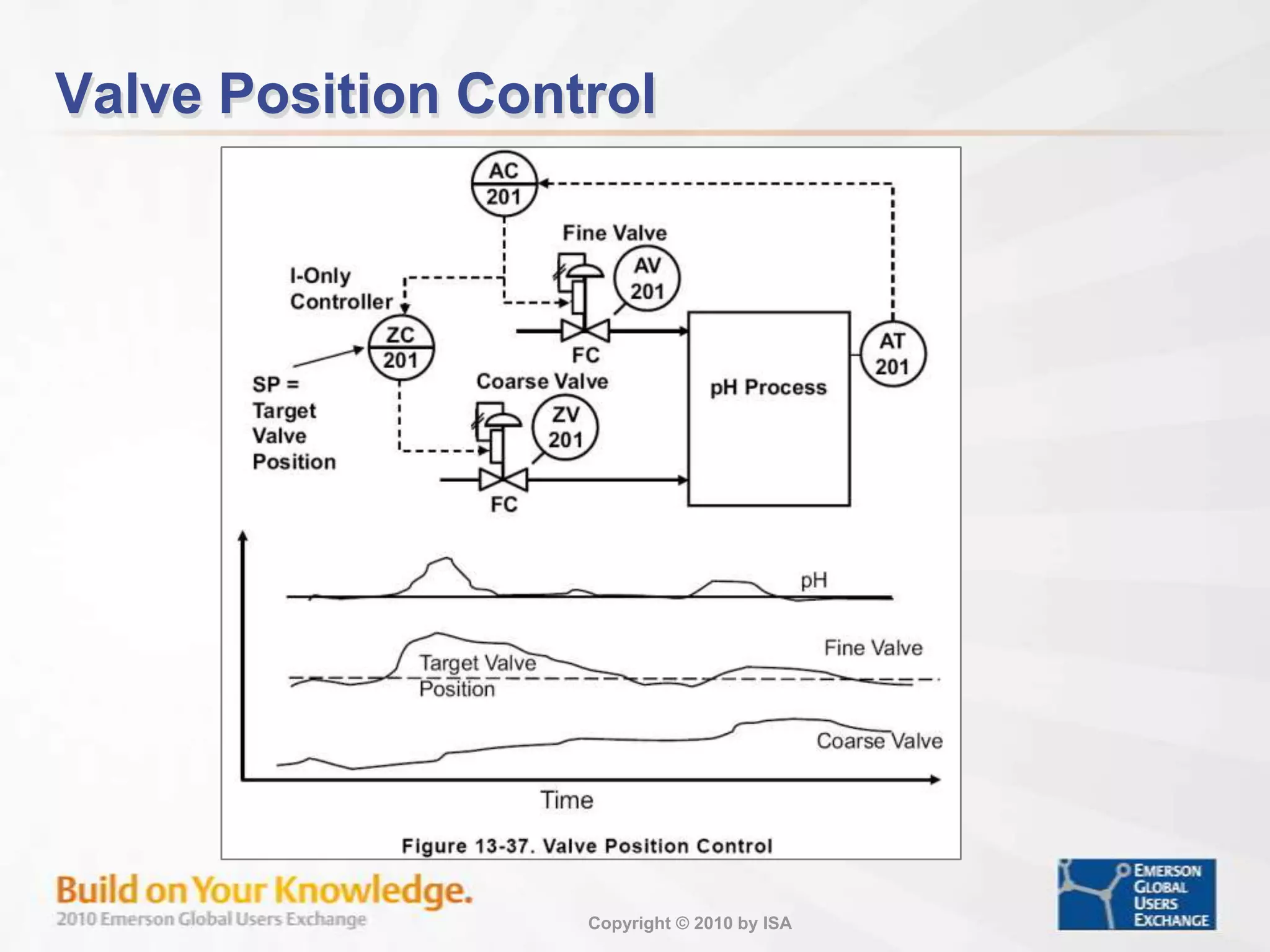
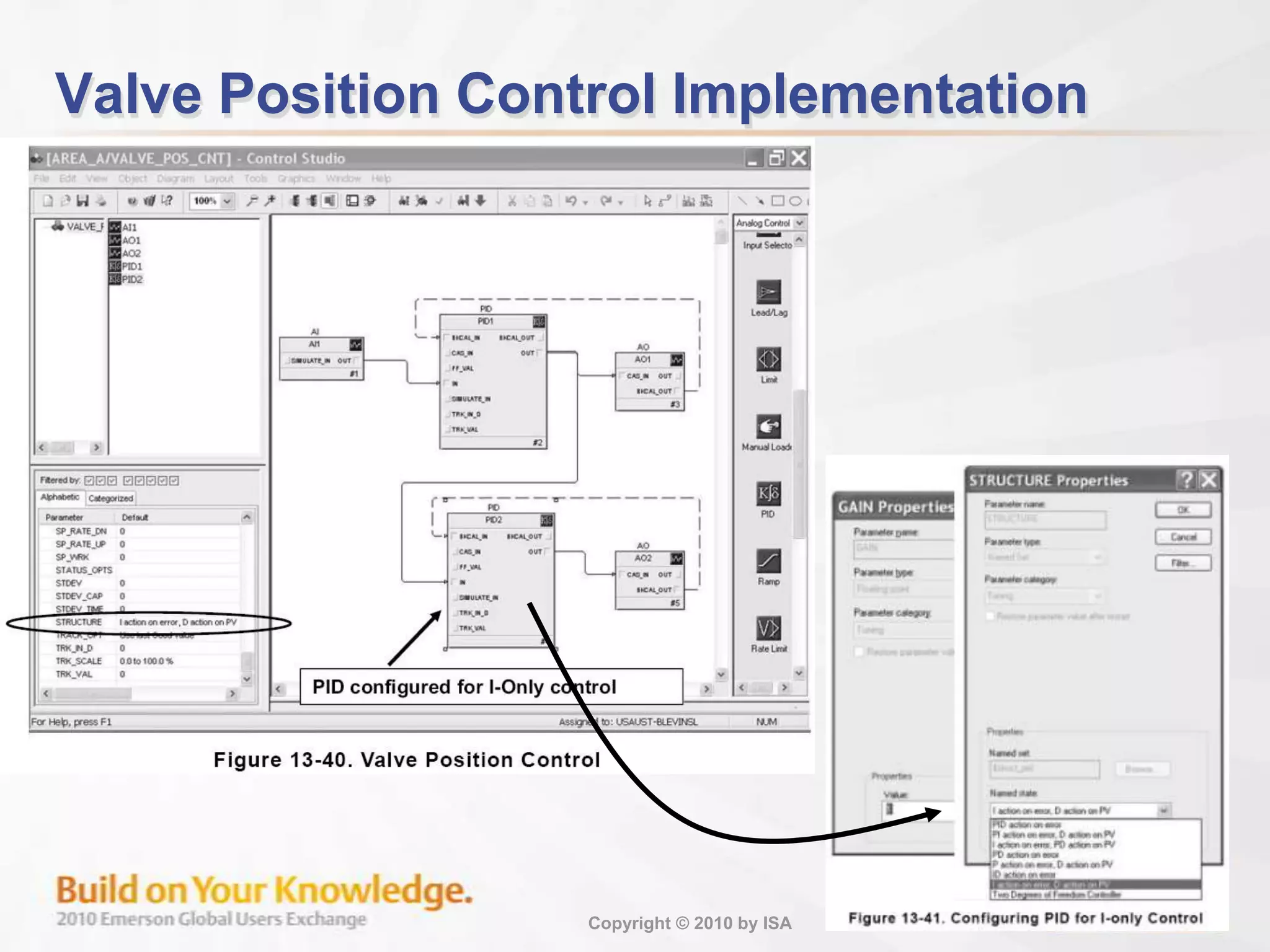
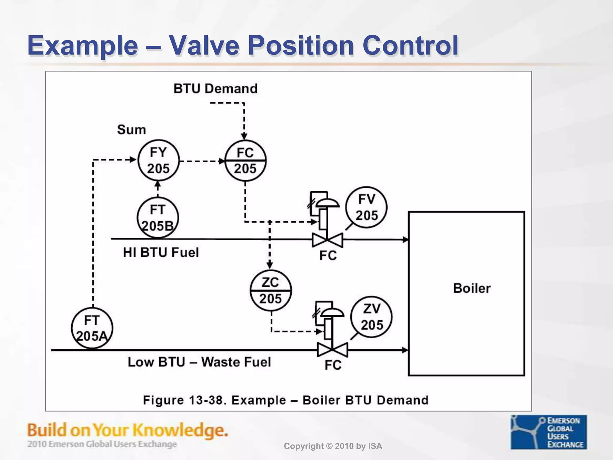
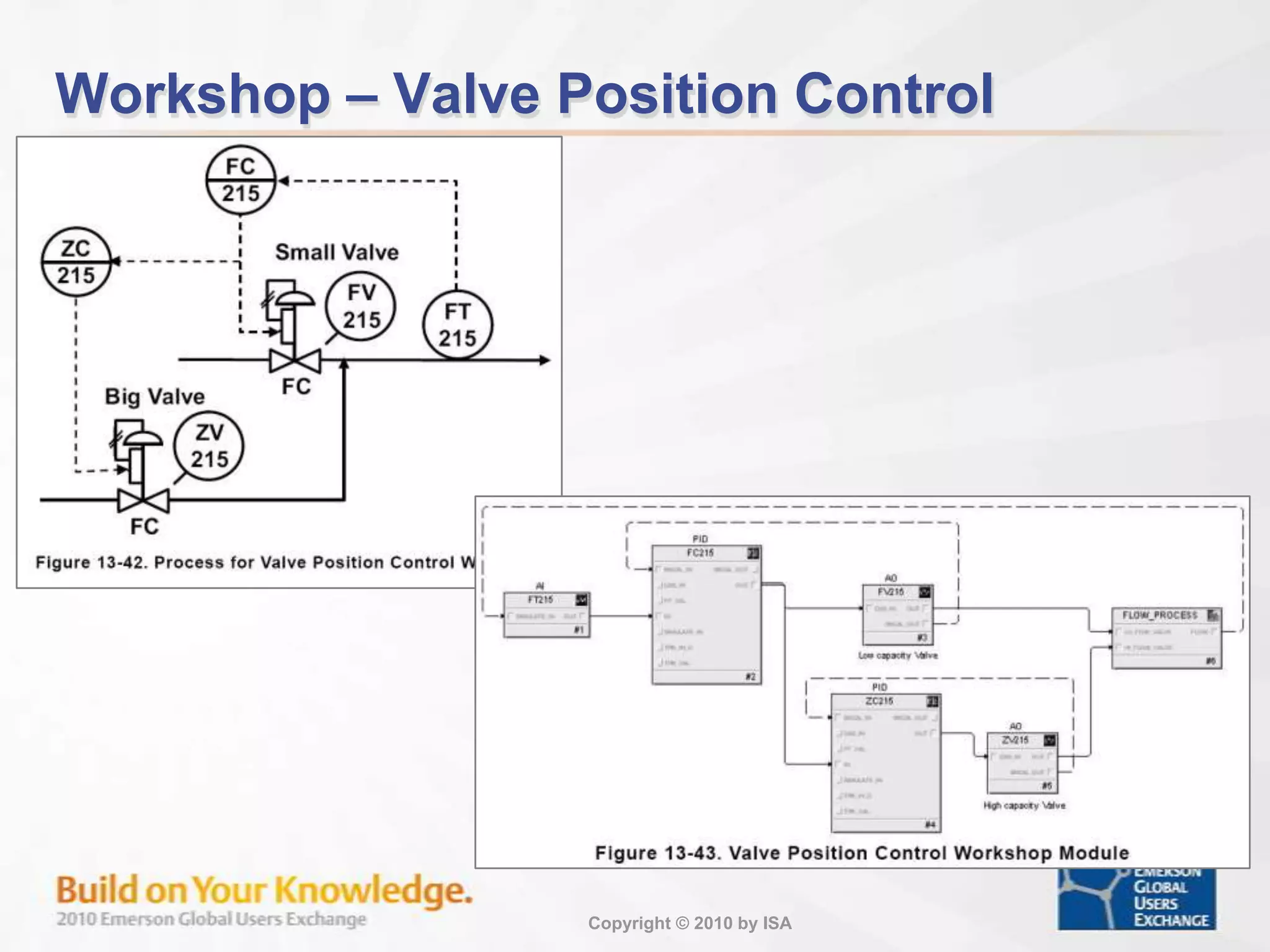
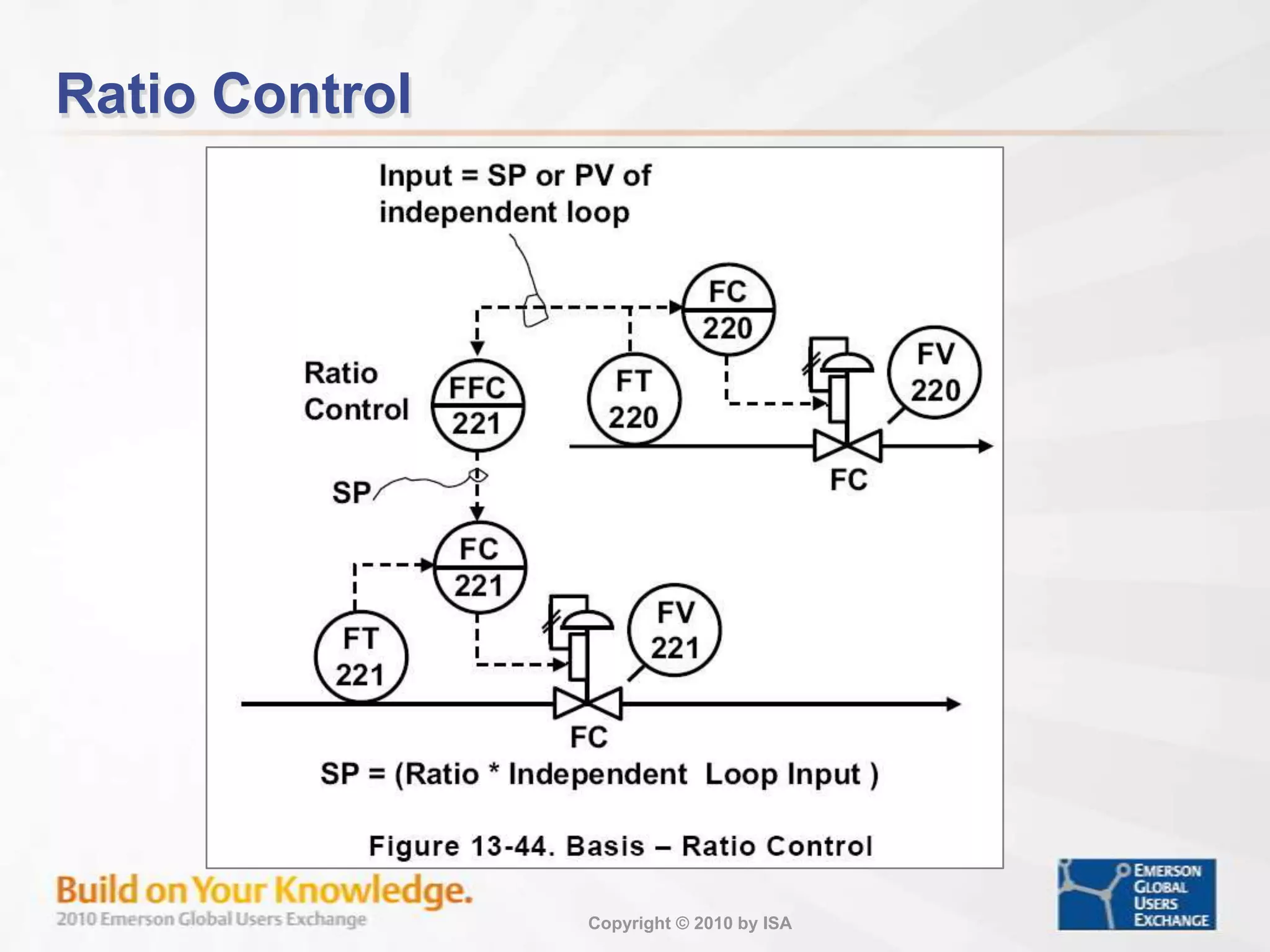
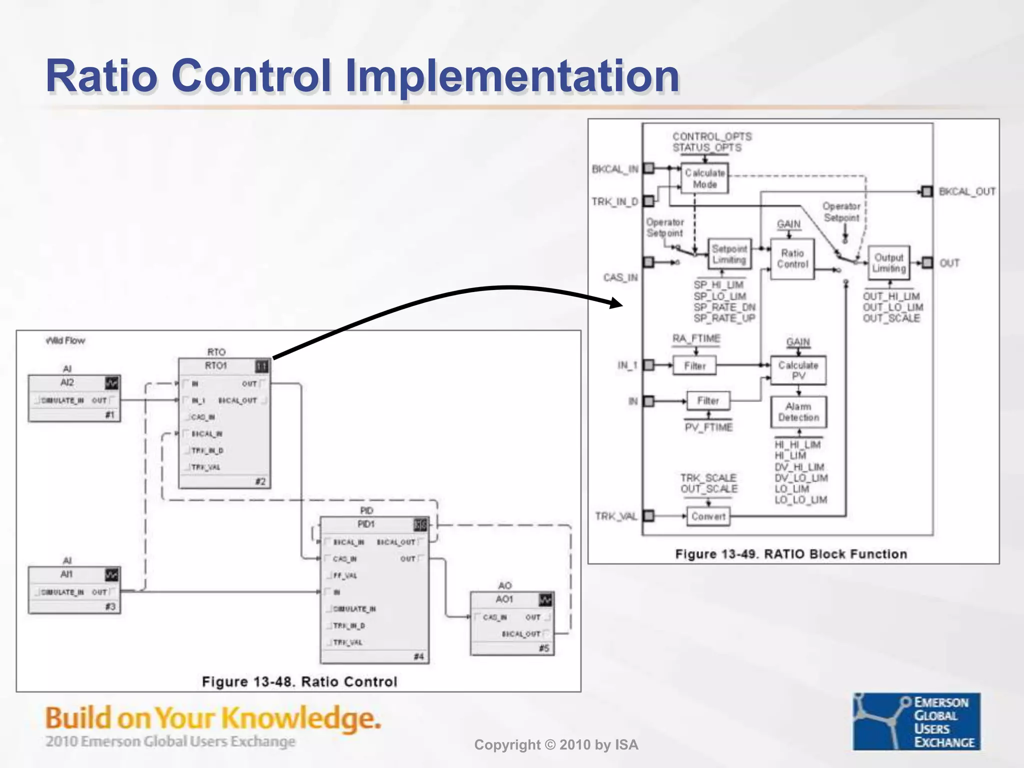
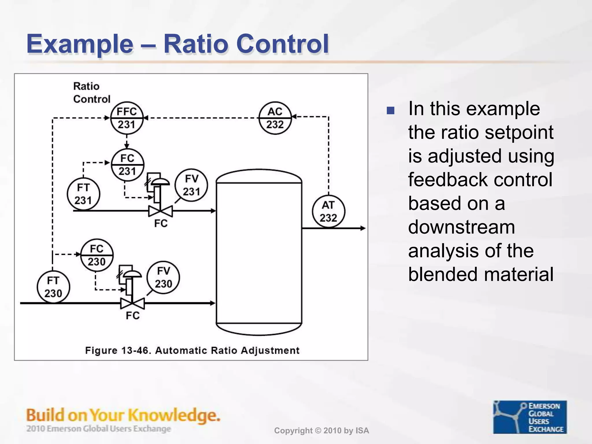
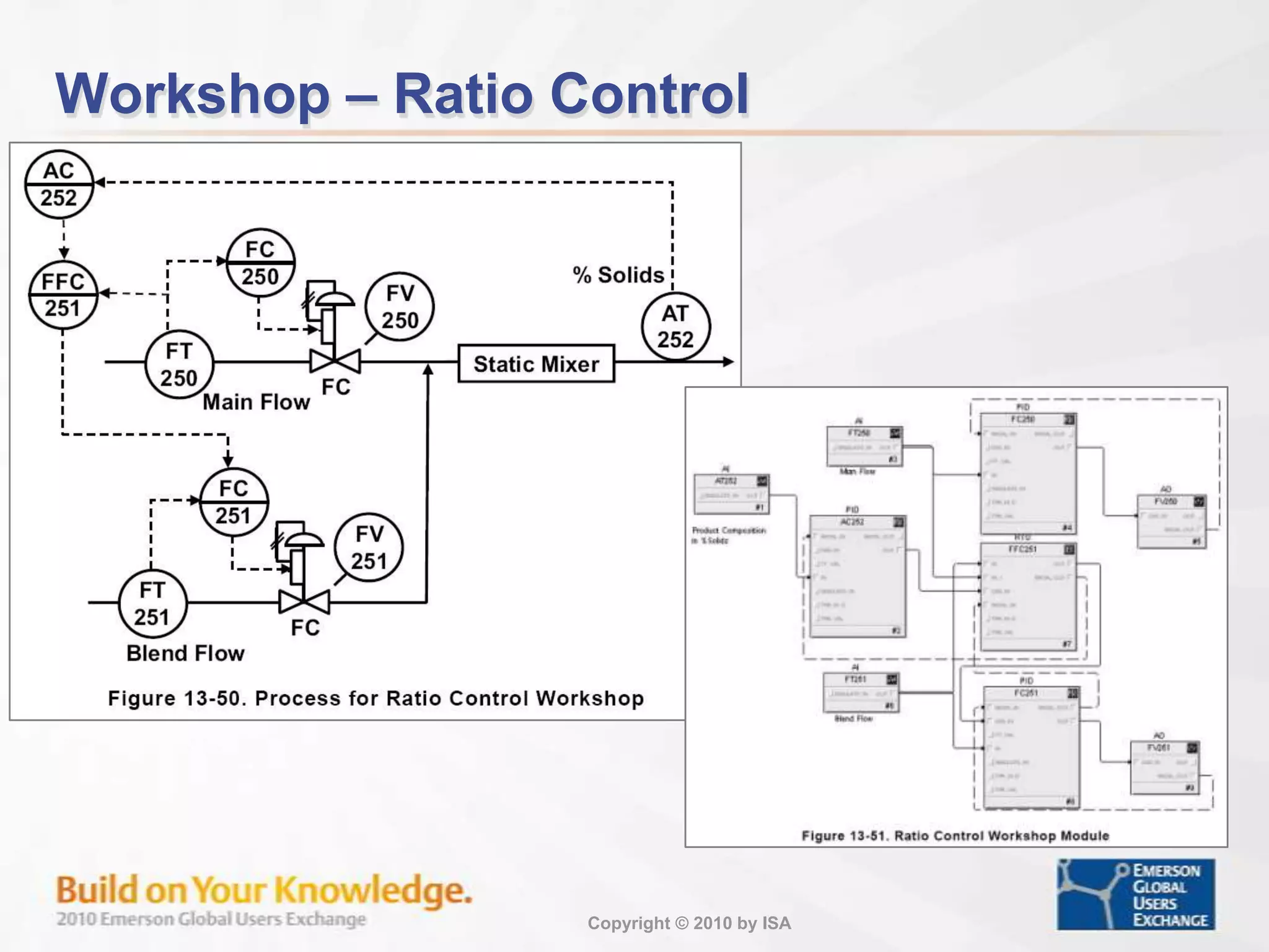
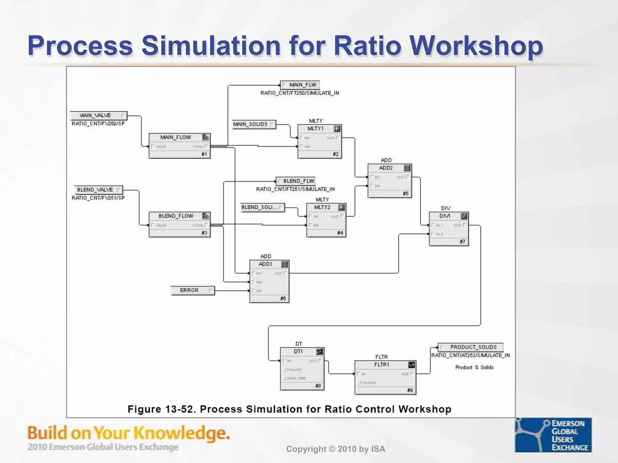
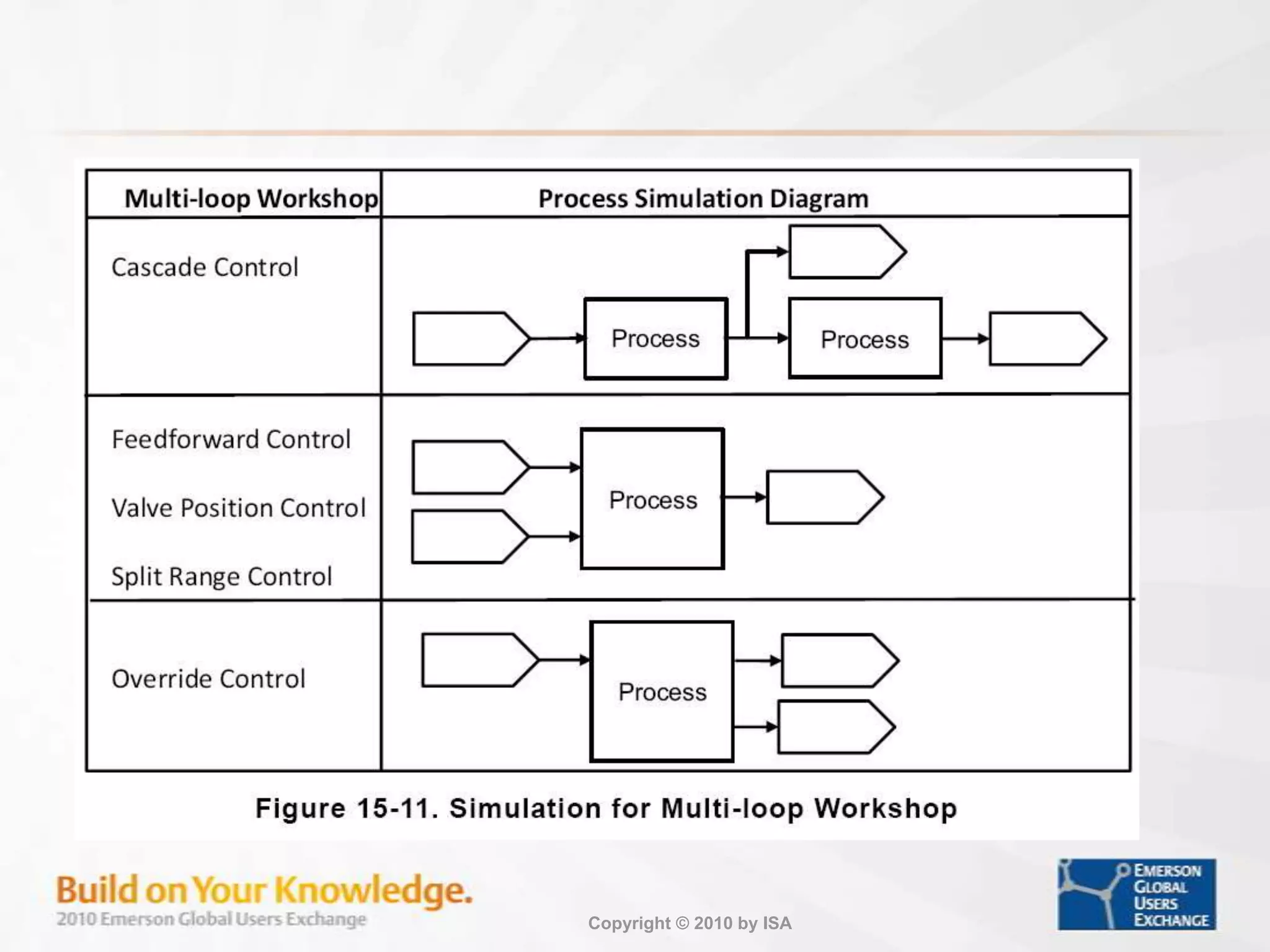
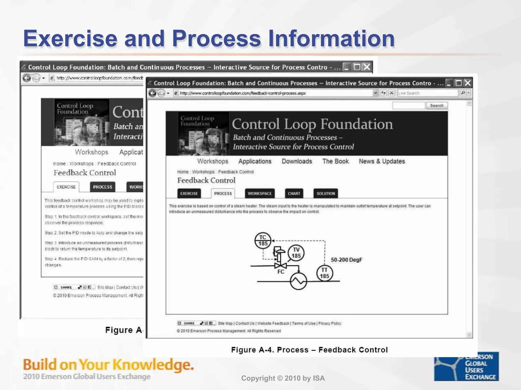
Discussion of single loop control, manual implementation to complex feedback systems and their workshops.
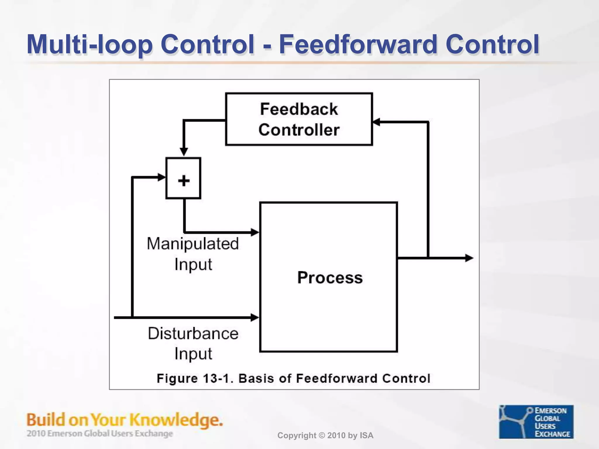
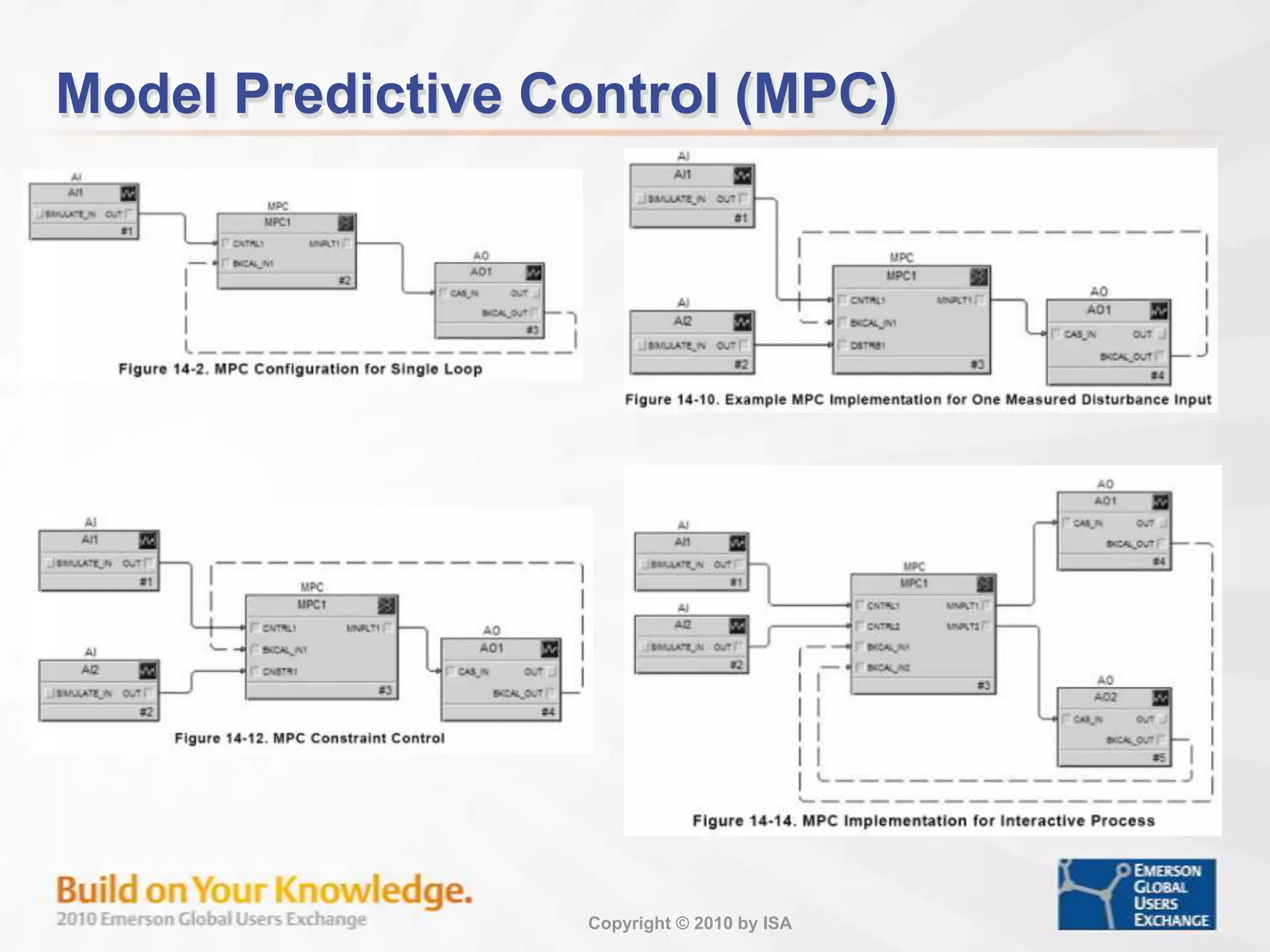
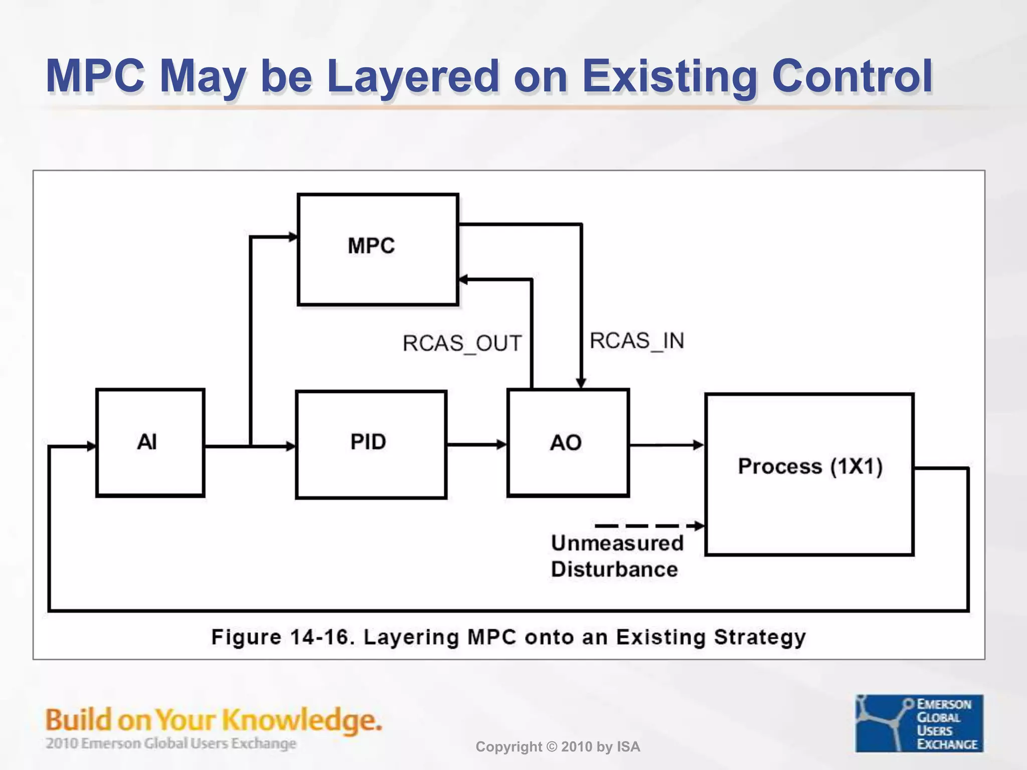
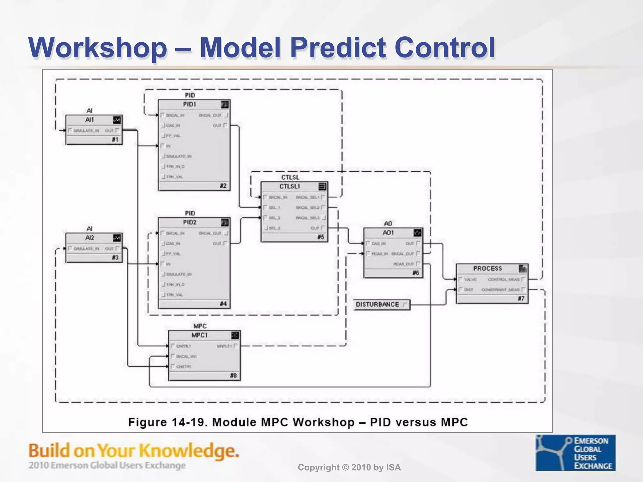
Introduction to model predictive control and its application for process constraint management.
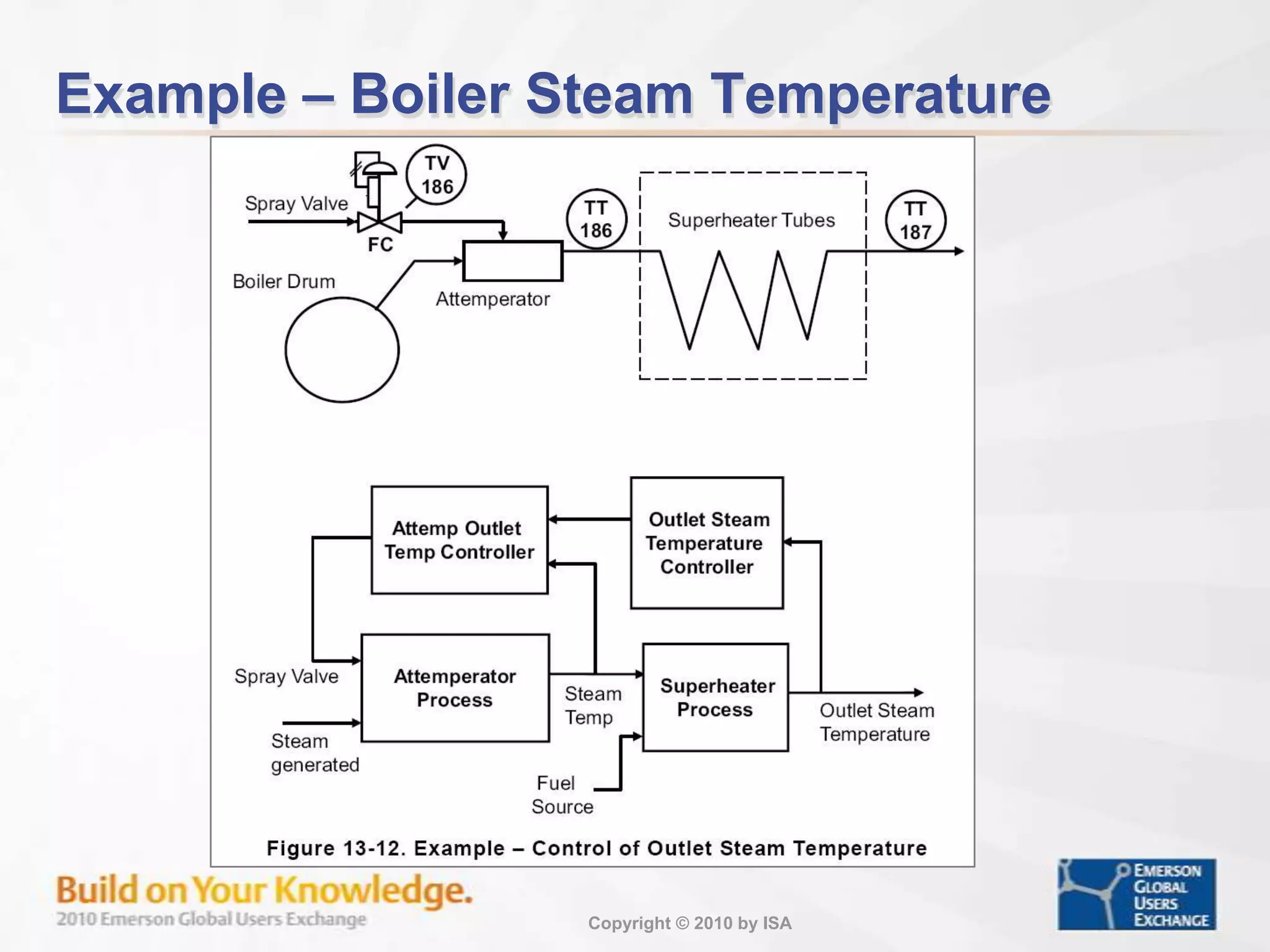
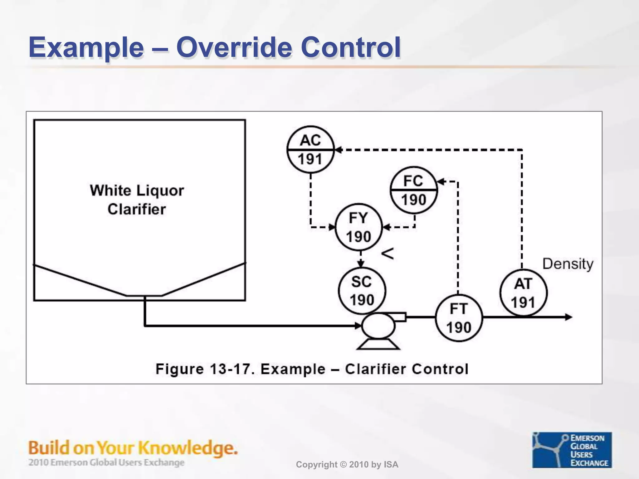
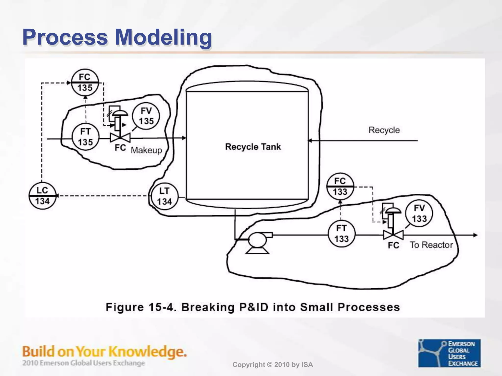
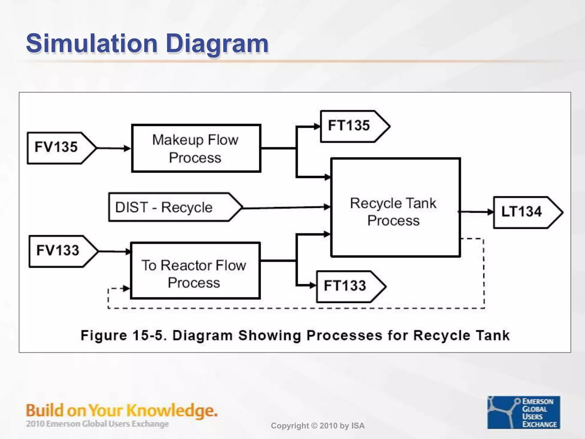
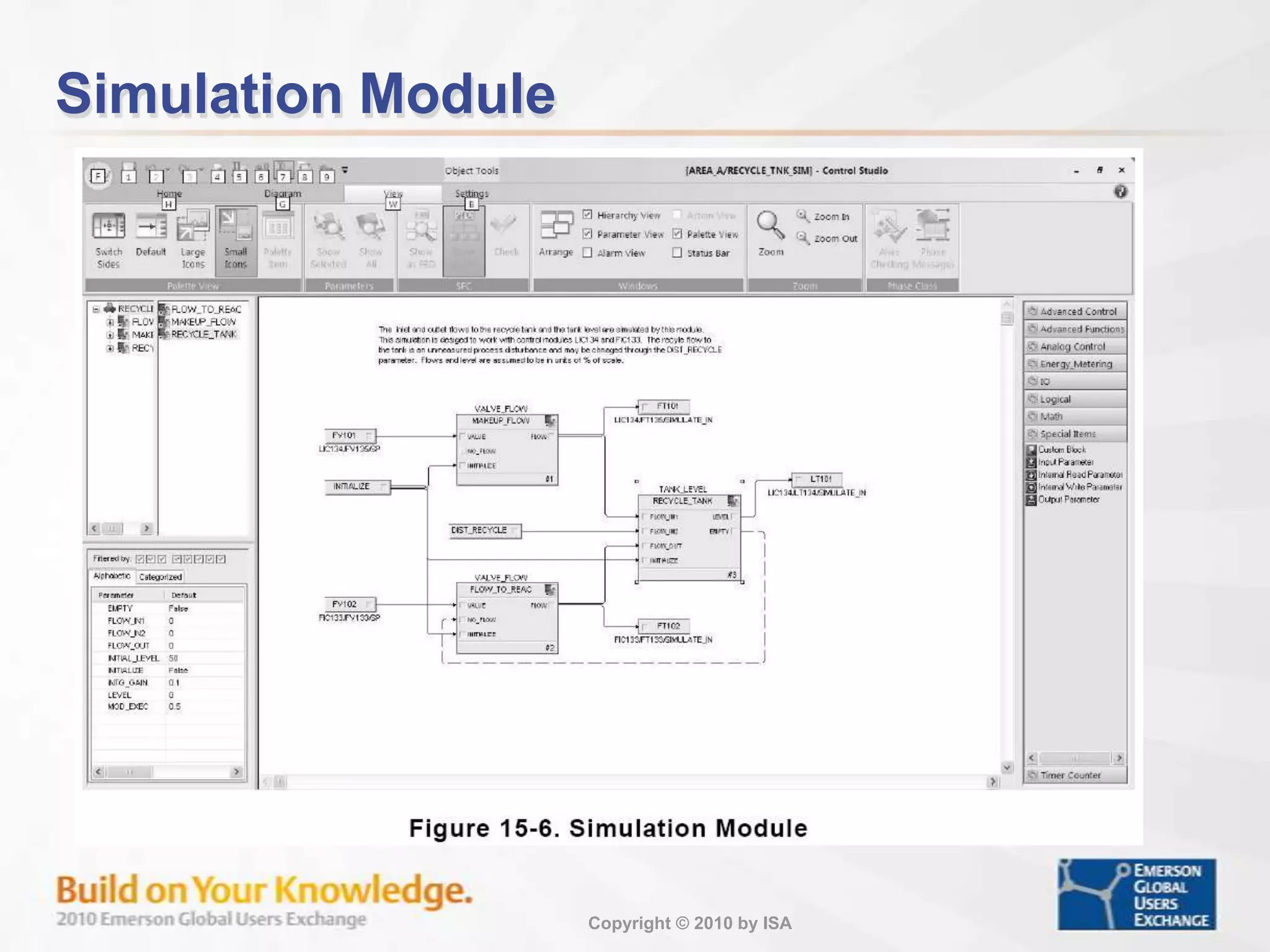
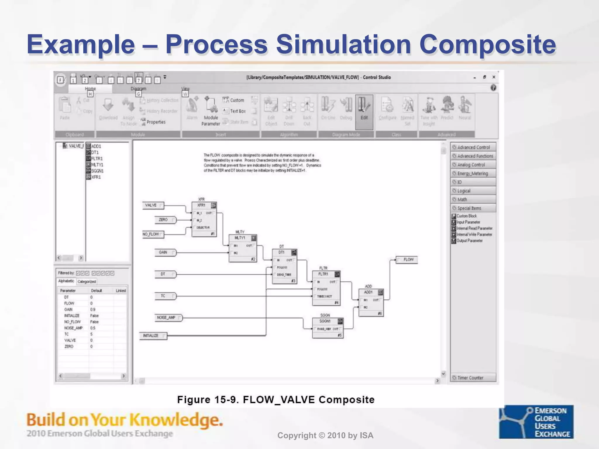
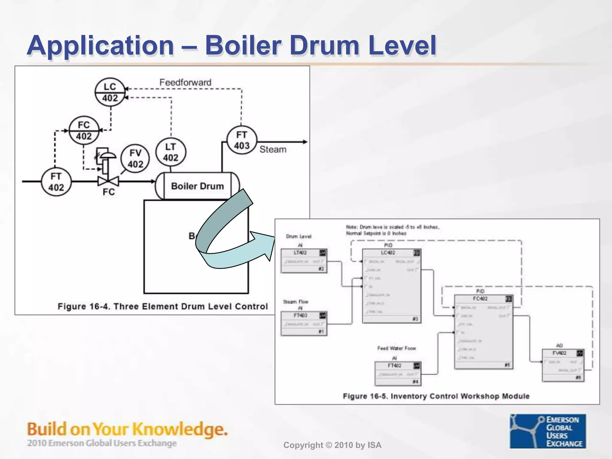
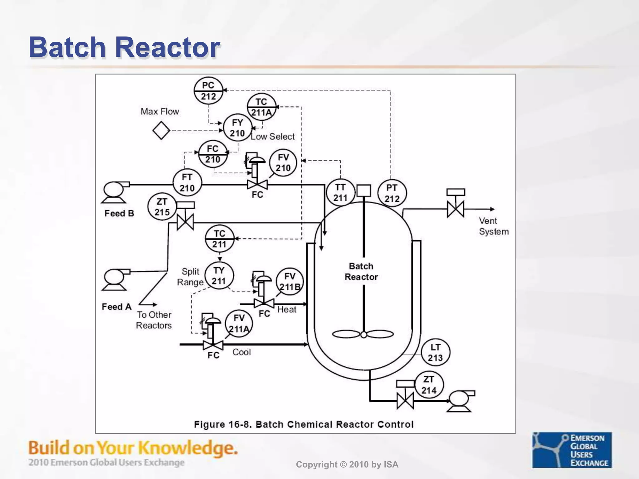
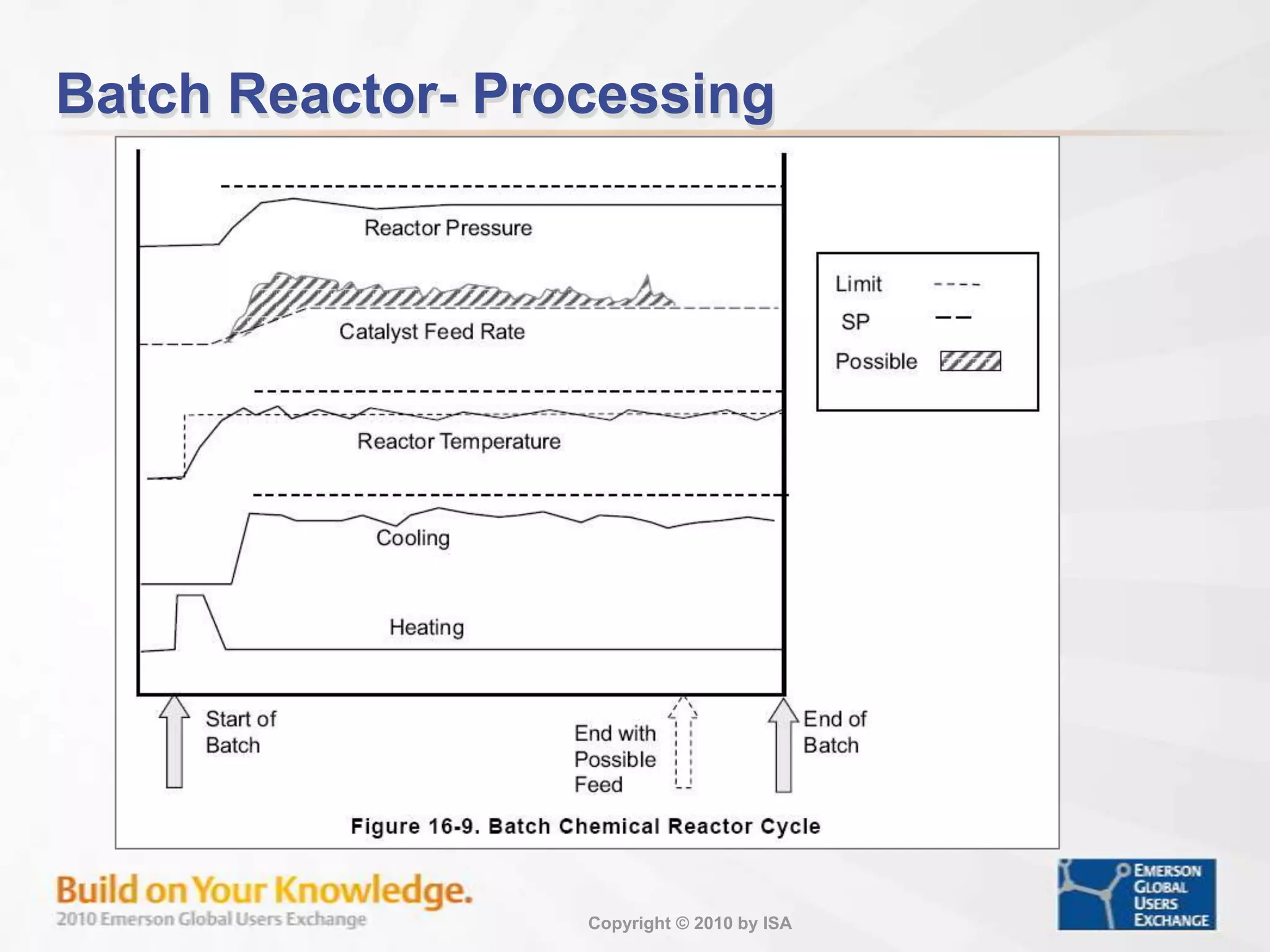
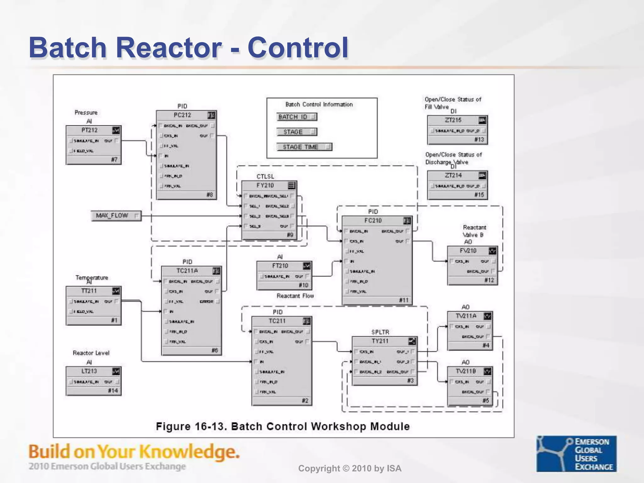
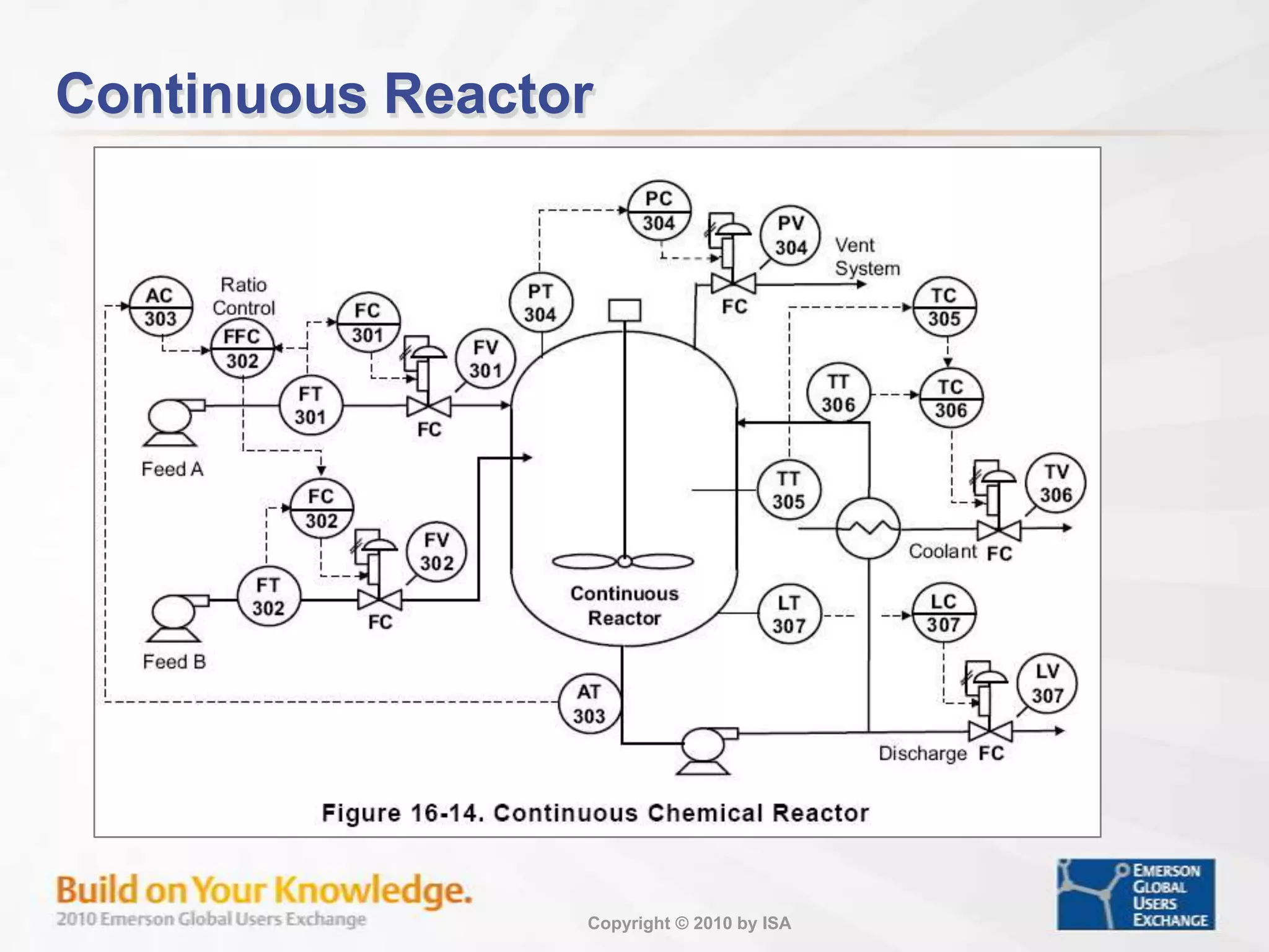
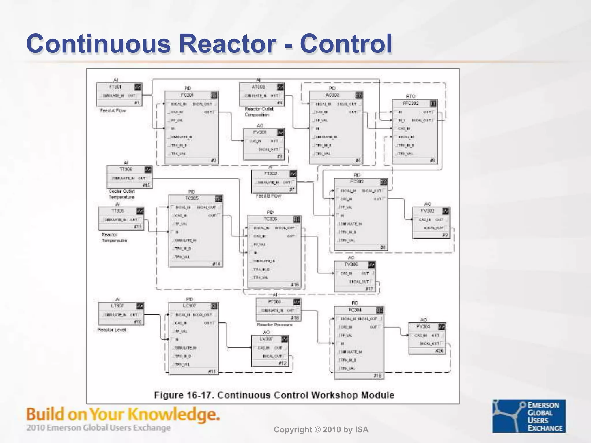
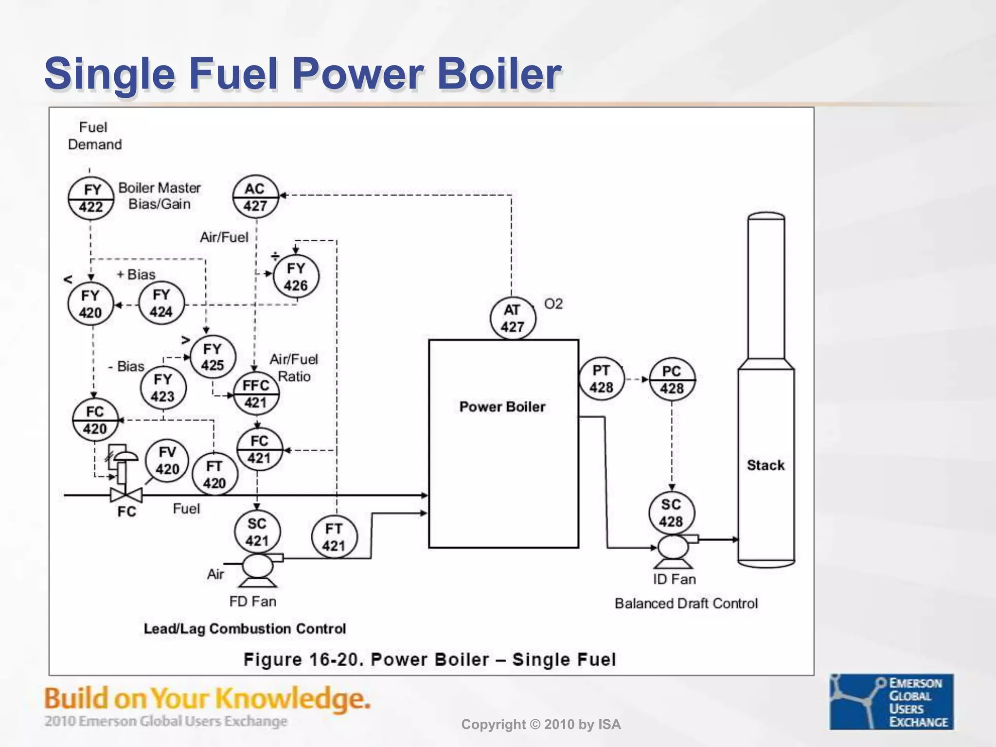
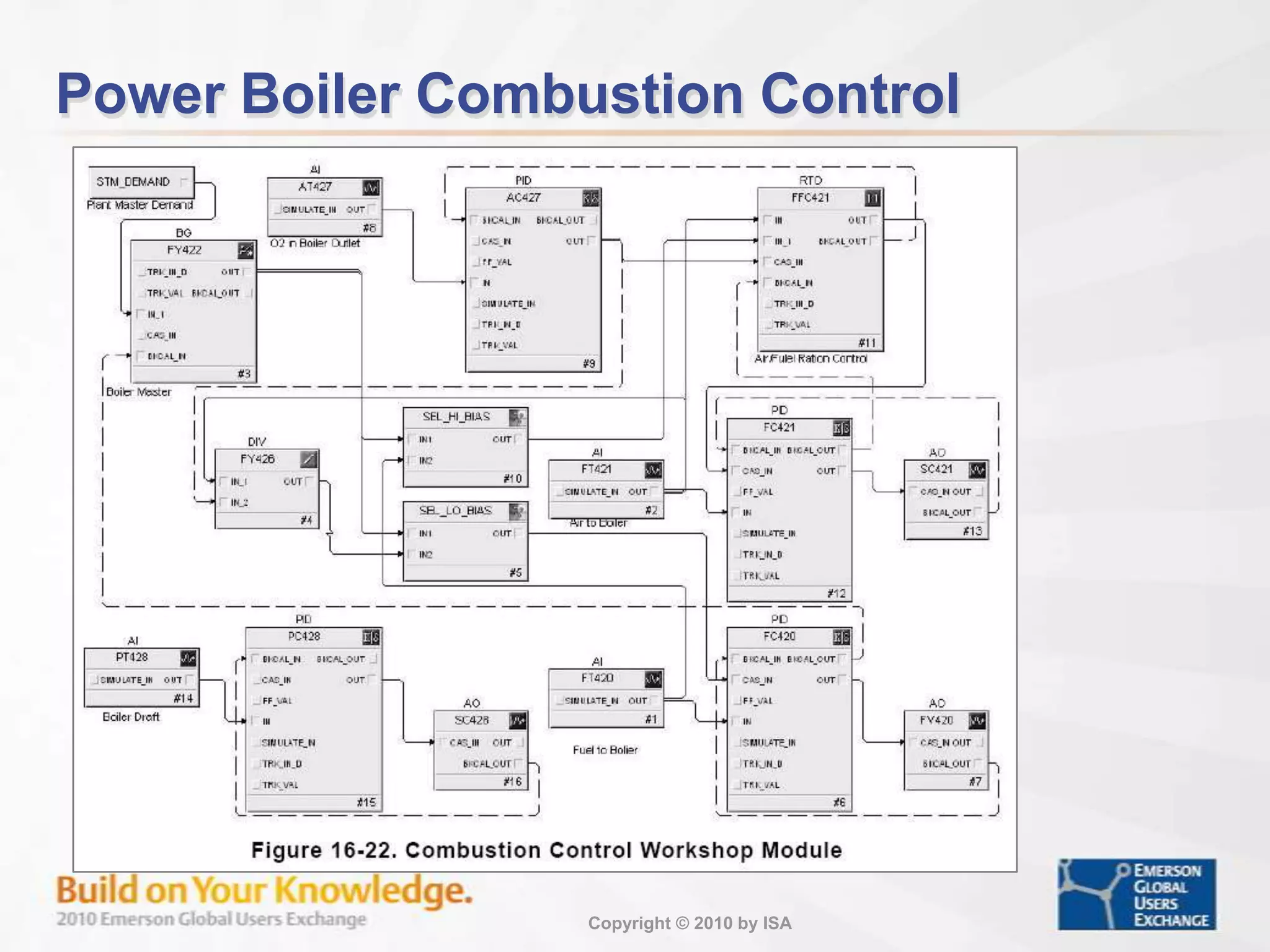
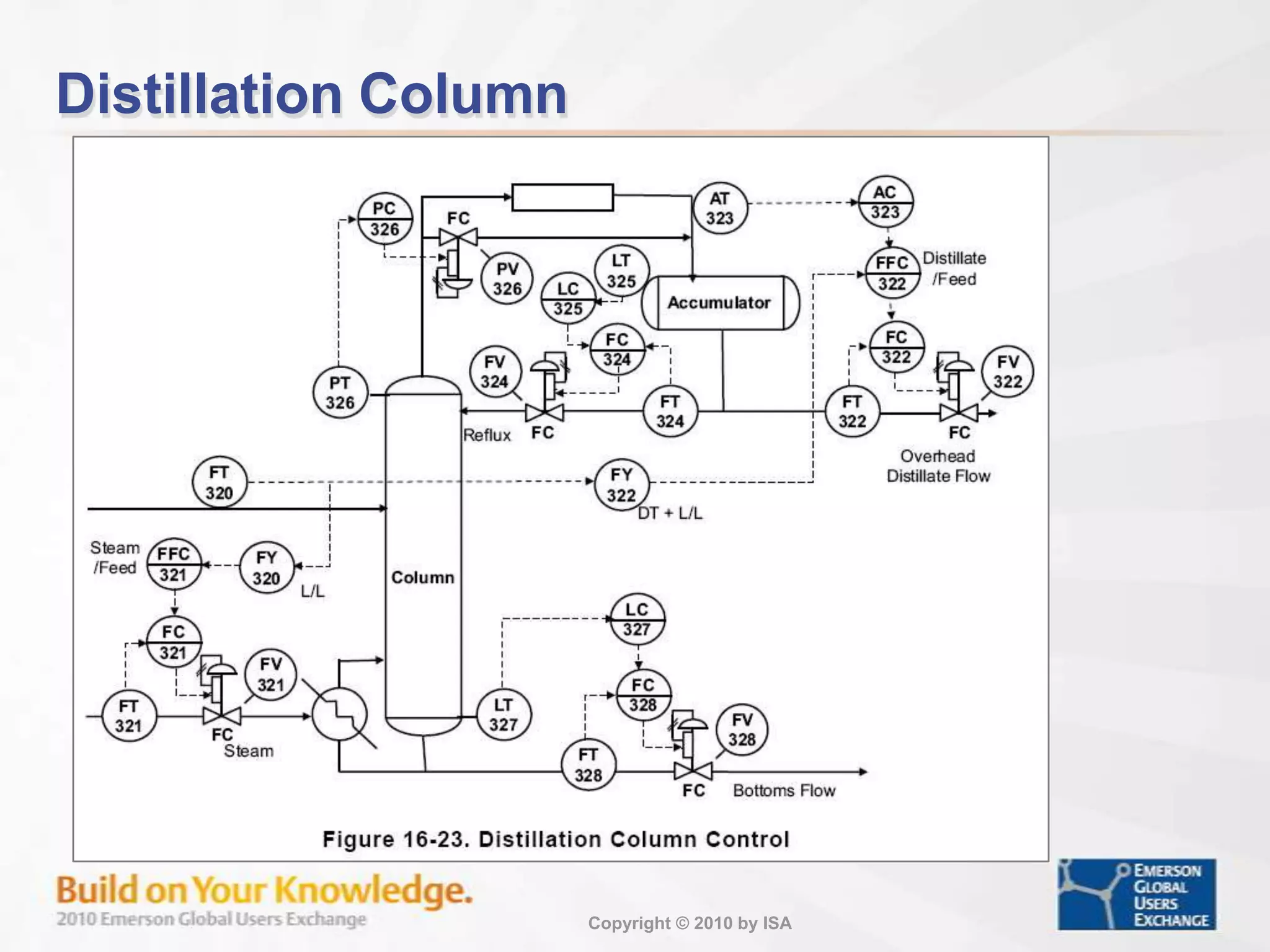
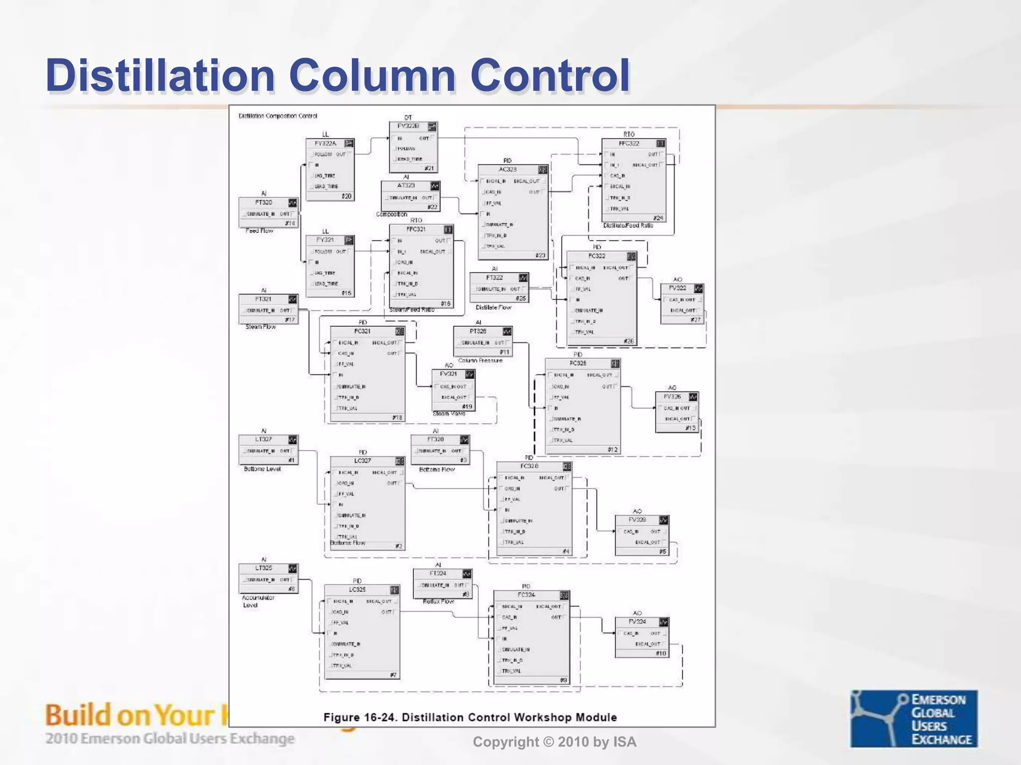
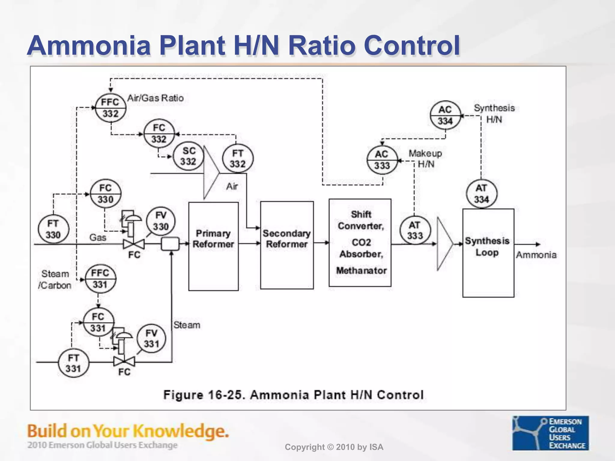
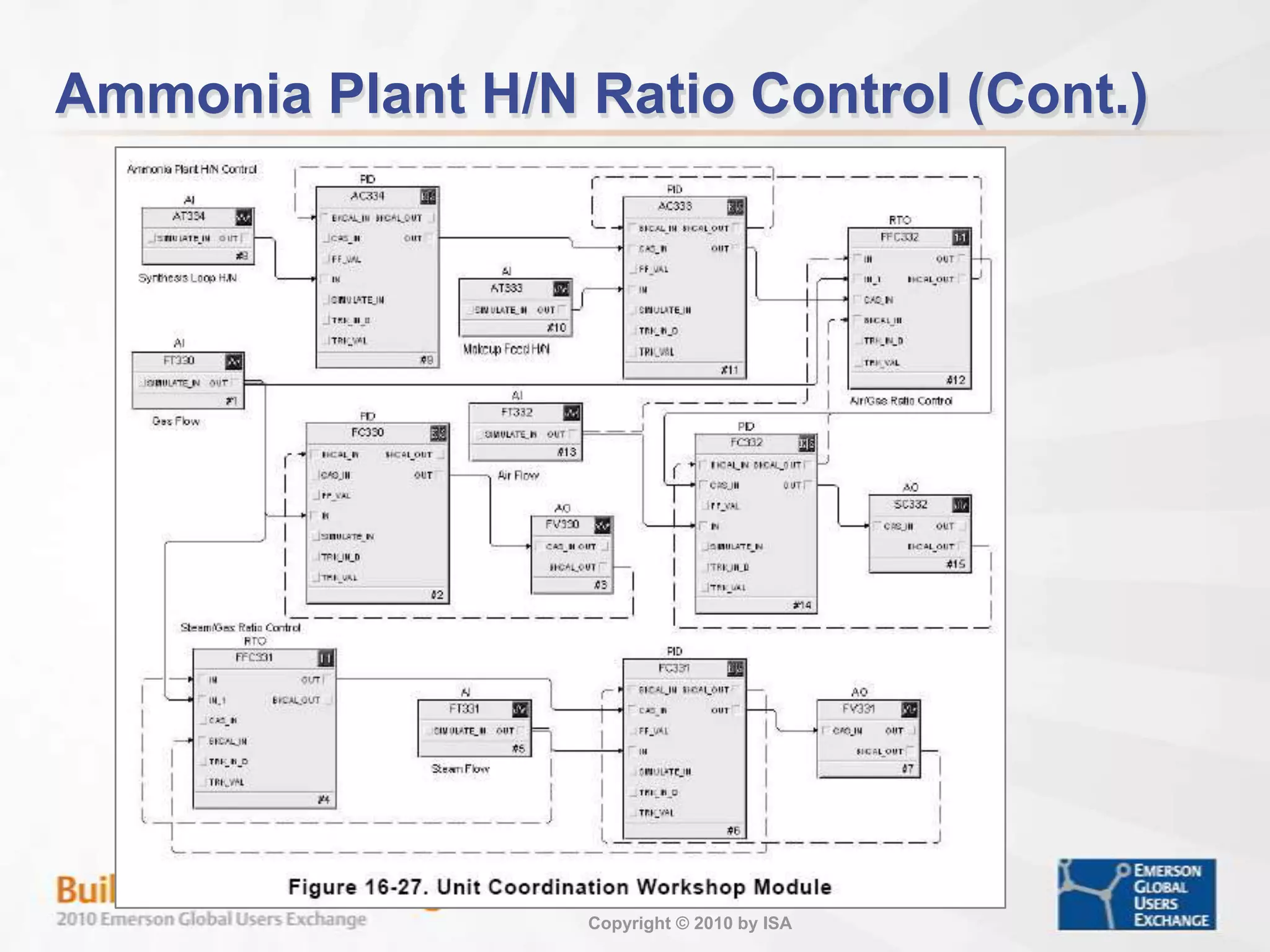
Applications of control strategies in batch and continuous reactors, demonstrating practical scenarios.
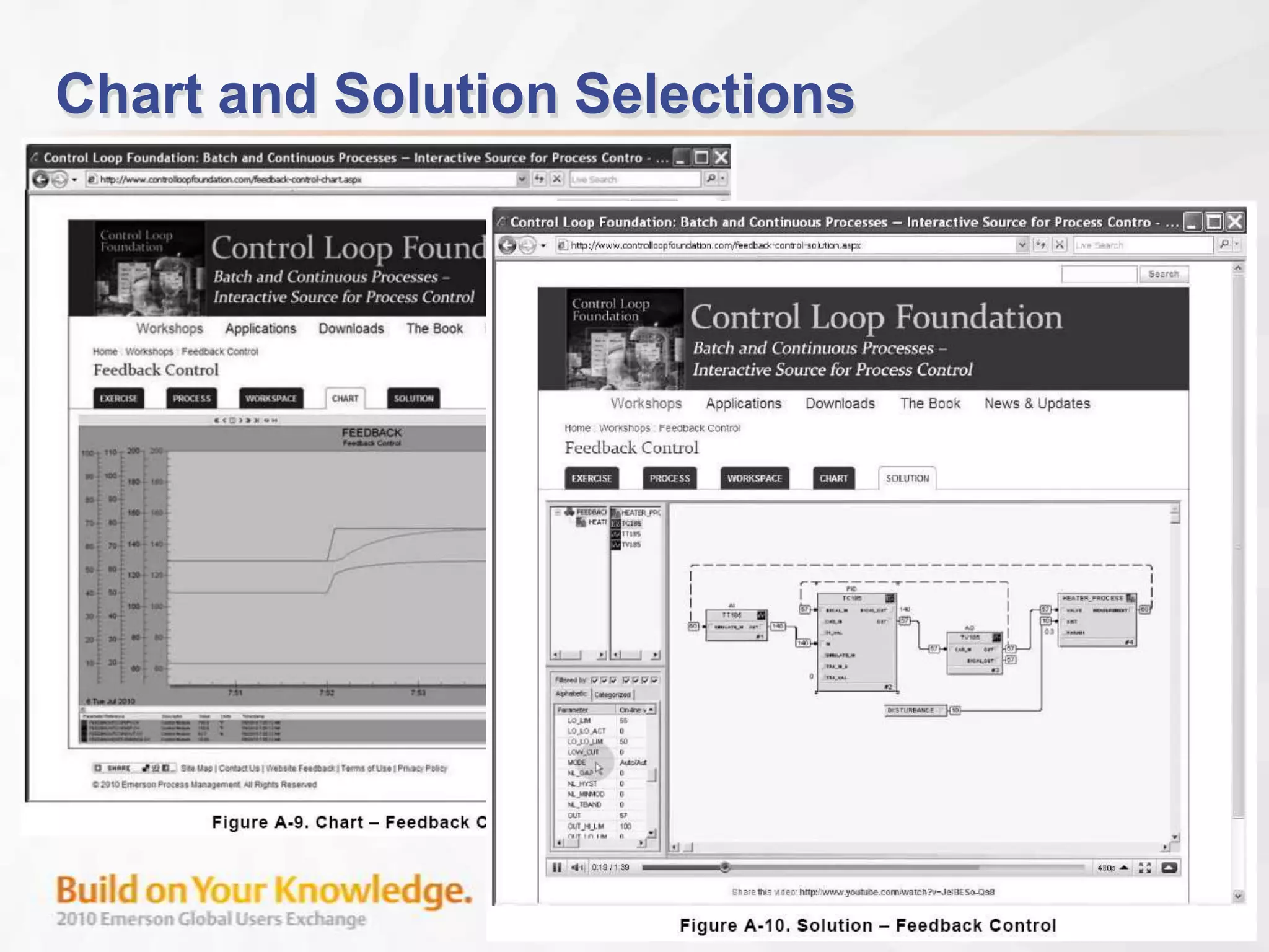
Course summary, feedback opportunities, and resources for further education and workshop registration.