The document outlines the input/output organization of a computer, detailing components such as peripheral devices, interfaces, and methods of data transfer like programmed I/O and direct memory access (DMA). It describes the importance of I/O modules, including control, timing, and error detection functions, along with different I/O commands and configurations. Additionally, it discusses interrupt-driven I/O operations and the complexities involved in DMA to facilitate efficient communication between the CPU and peripherals.
I/O Organization The Input/ output organization of computer depends upon the size of computer and the peripherals connected to it. The I/O Subsystem of the computer, provides an efficient mode of communication between the central system and the outside environment.
4.
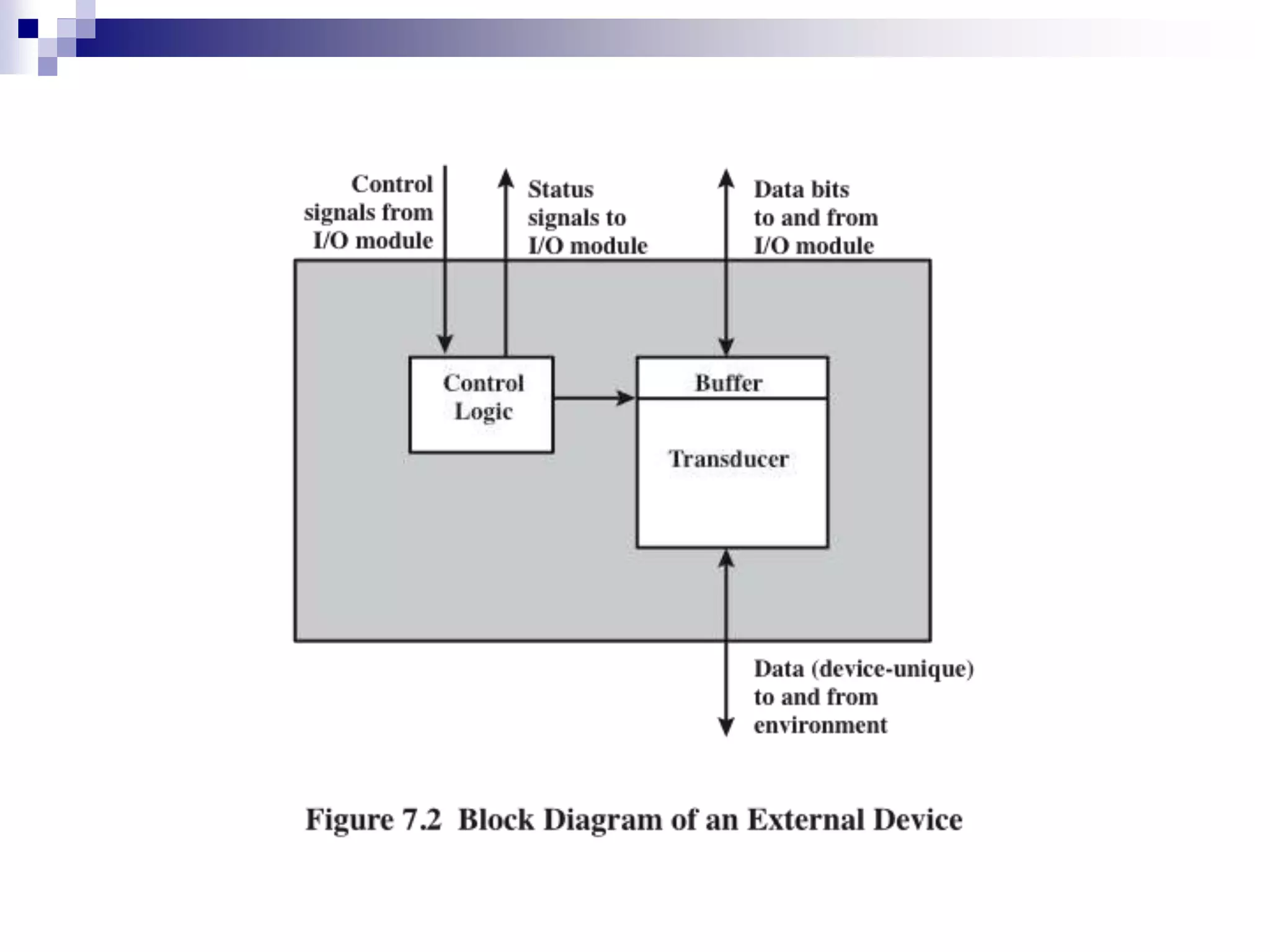
Peripheral Devices An externaldevice connected to an I/O module Provide a means of exchanging data between the external device environment and the computer. Attach to the computer by a link to an I/O module The link is used to exchange control, status, and data between the I/O module and the external device.
5.
Peripheral Devices The mostcommon input output devices are: i) Monitor ii) Keyboard iii) Mouse iv) Printer v) Magnetic tapes The devices that are under the direct control of the computer are said to be connected online.
6.
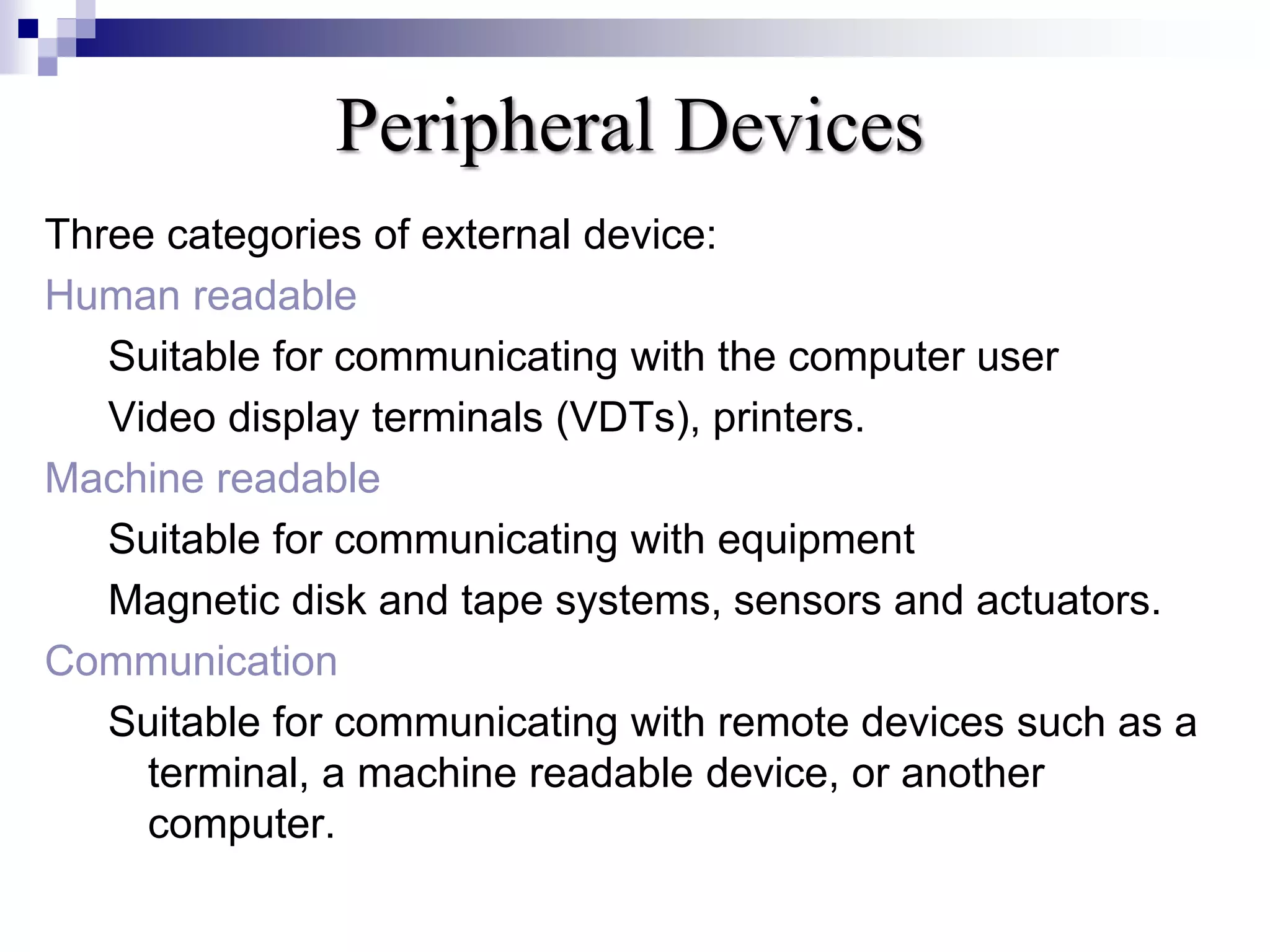
Peripheral Devices Three categoriesof external device: Human readable Suitable for communicating with the computer user Video display terminals (VDTs), printers. Machine readable Suitable for communicating with equipment Magnetic disk and tape systems, sensors and actuators. Communication Suitable for communicating with remote devices such as a terminal, a machine readable device, or another computer.
8.
Input - OutputInterface Input Output Interface provides a method for transferring information between internal storage (such as memory and CPU registers) and external I/O devices. Peripherals connected to a computer need special communication links for interfacing them with the central processing unit.
9.
Input - OutputInterface The purpose of communication link is to resolve the differences that exist between the central computer and each peripheral.
10.
The Major Differencesare:- 1. Peripherals are electromechanically and electromagnetic devices and their manner of operation of the CPU and memory, which are electronic devices. Therefore, a conversion of signal values may be needed. 2. The data transfer rate of peripherals is usually slower than the transfer rate of CPU and consequently, a synchronization mechanism may be needed.
11.
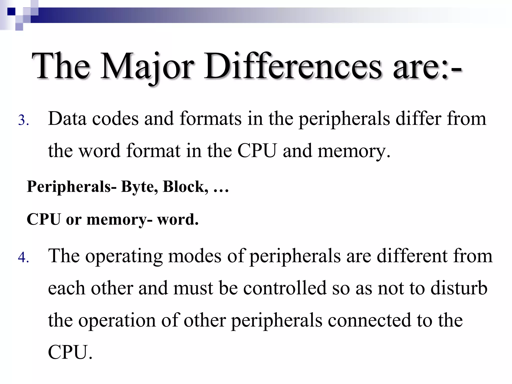
The Major Differencesare:- 3. Data codes and formats in the peripherals differ from the word format in the CPU and memory. Peripherals- Byte, Block, … CPU or memory- word. 4. The operating modes of peripherals are different from each other and must be controlled so as not to disturb the operation of other peripherals connected to the CPU.
12.
Input - OutputInterface To Resolve these differences, computer systems include special hardware components between the CPU and Peripherals to supervises and synchronizes all input and out transfers. These components are called Interface Units because they interface between the processor bus and the peripheral devices.
13.
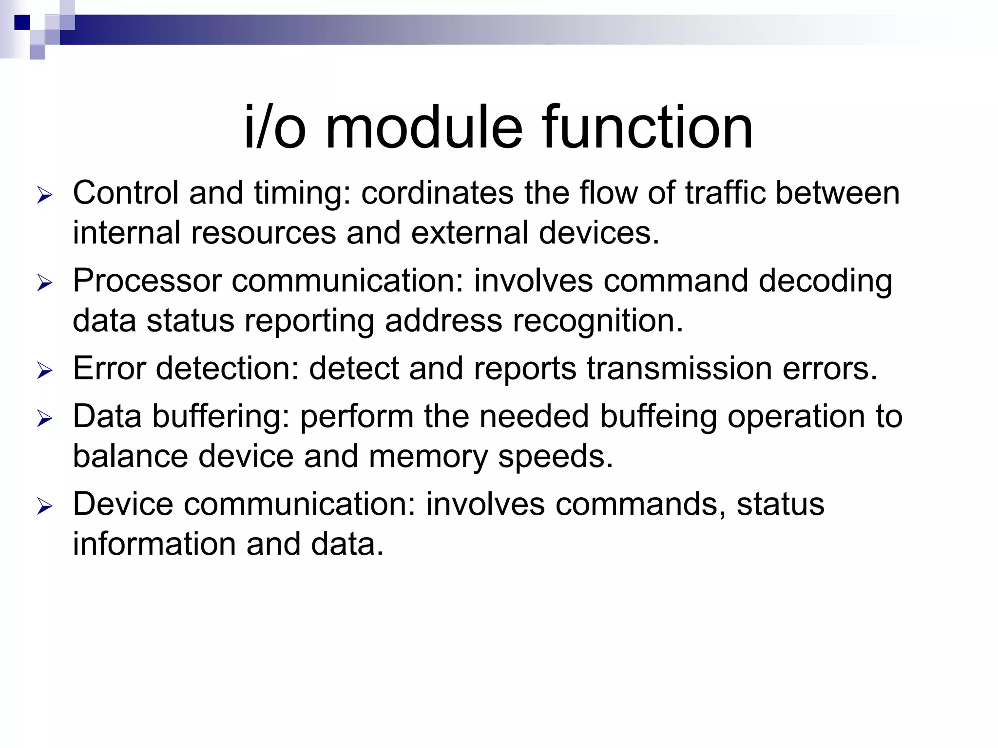
i/o module function Control and timing: cordinates the flow of traffic between internal resources and external devices. Processor communication: involves command decoding data status reporting address recognition. Error detection: detect and reports transmission errors. Data buffering: perform the needed buffeing operation to balance device and memory speeds. Device communication: involves commands, status information and data.
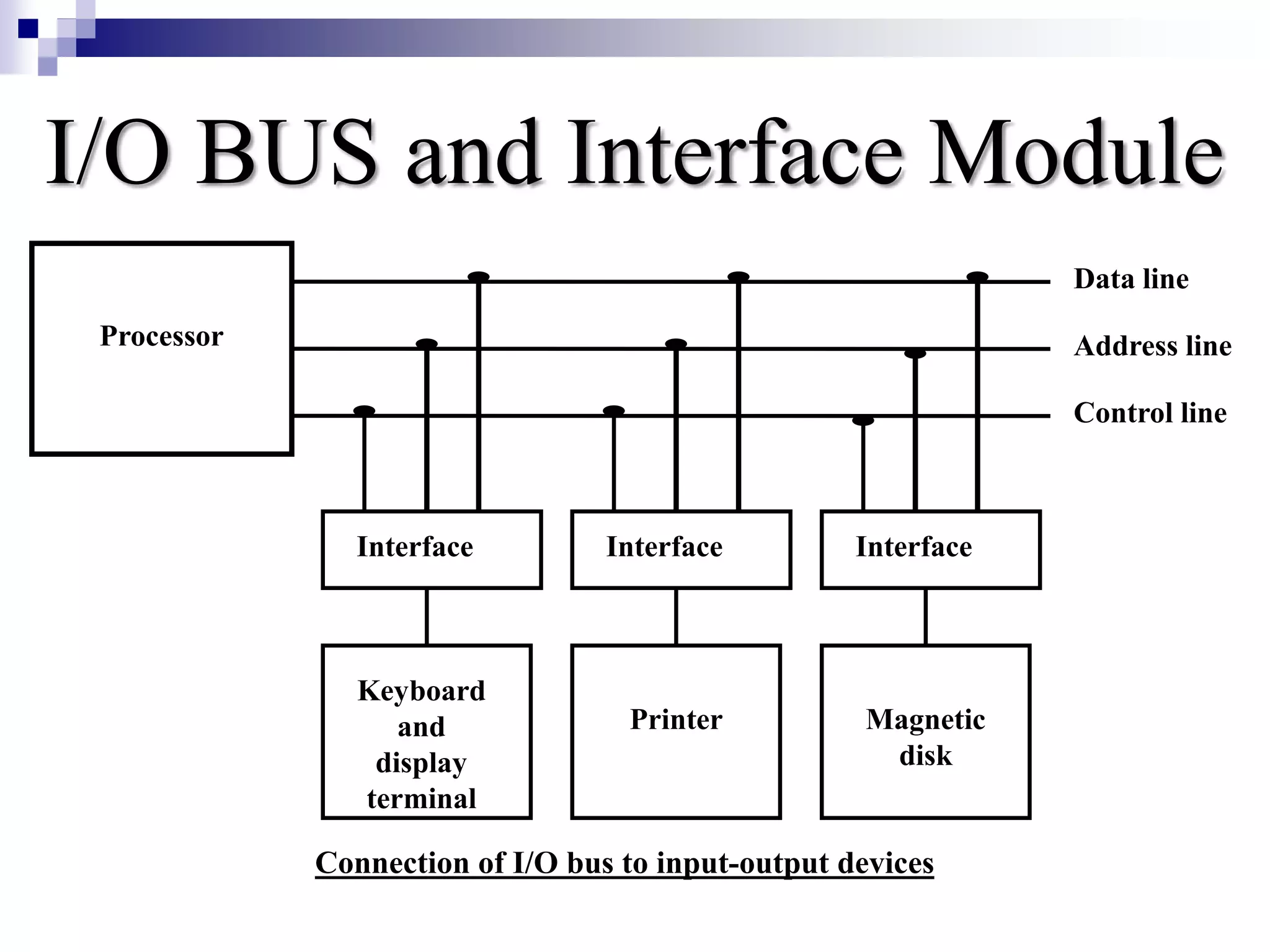
I/O BUS andInterface Module It defines the typical link between the processor and several peripherals. The I/O Bus consists of data lines, address lines and control lines.
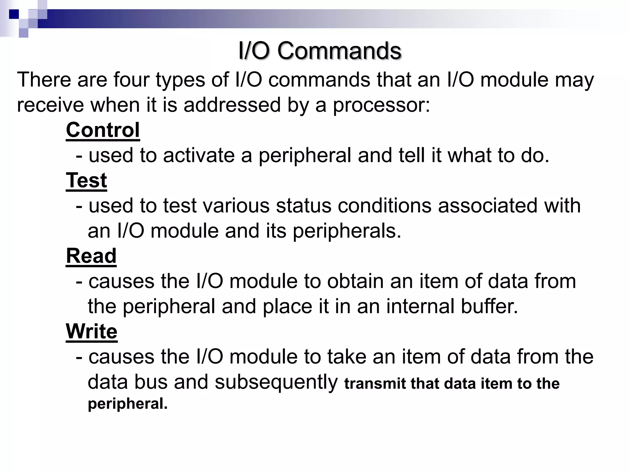
I/O Commands There arefour types of I/O commands that an I/O module may receive when it is addressed by a processor: Control - used to activate a peripheral and tell it what to do. Test - used to test various status conditions associated with an I/O module and its peripherals. Read - causes the I/O module to obtain an item of data from the peripheral and place it in an internal buffer. Write - causes the I/O module to take an item of data from the data bus and subsequently transmit that data item to the peripheral.
18.
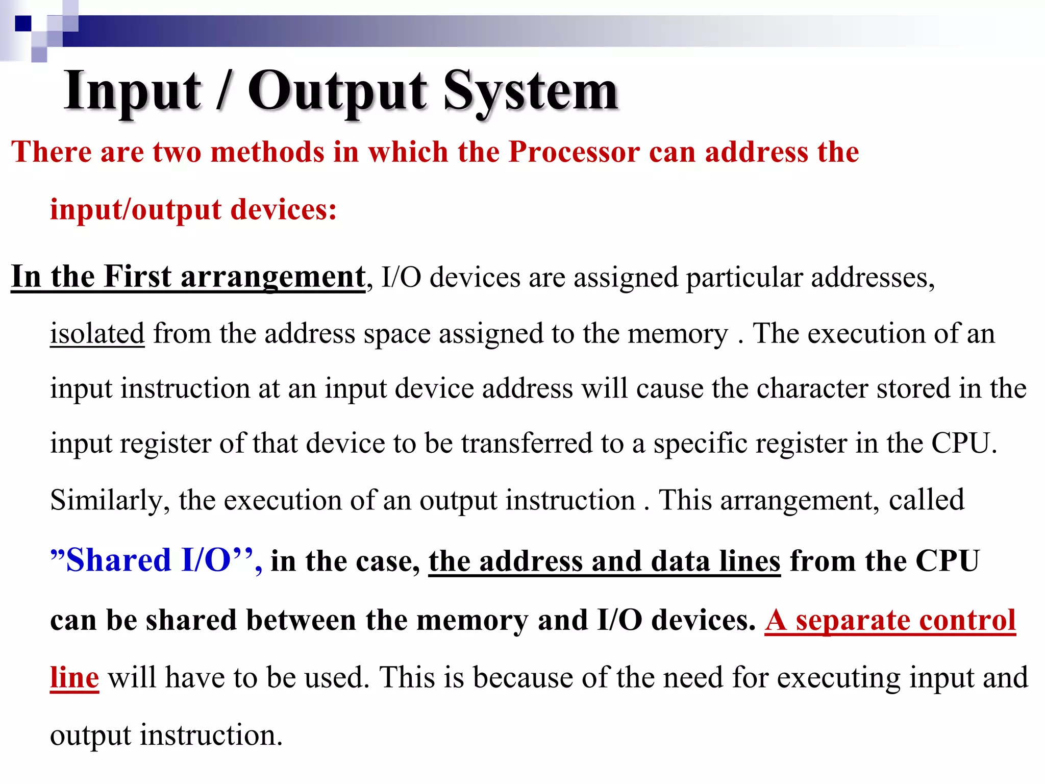
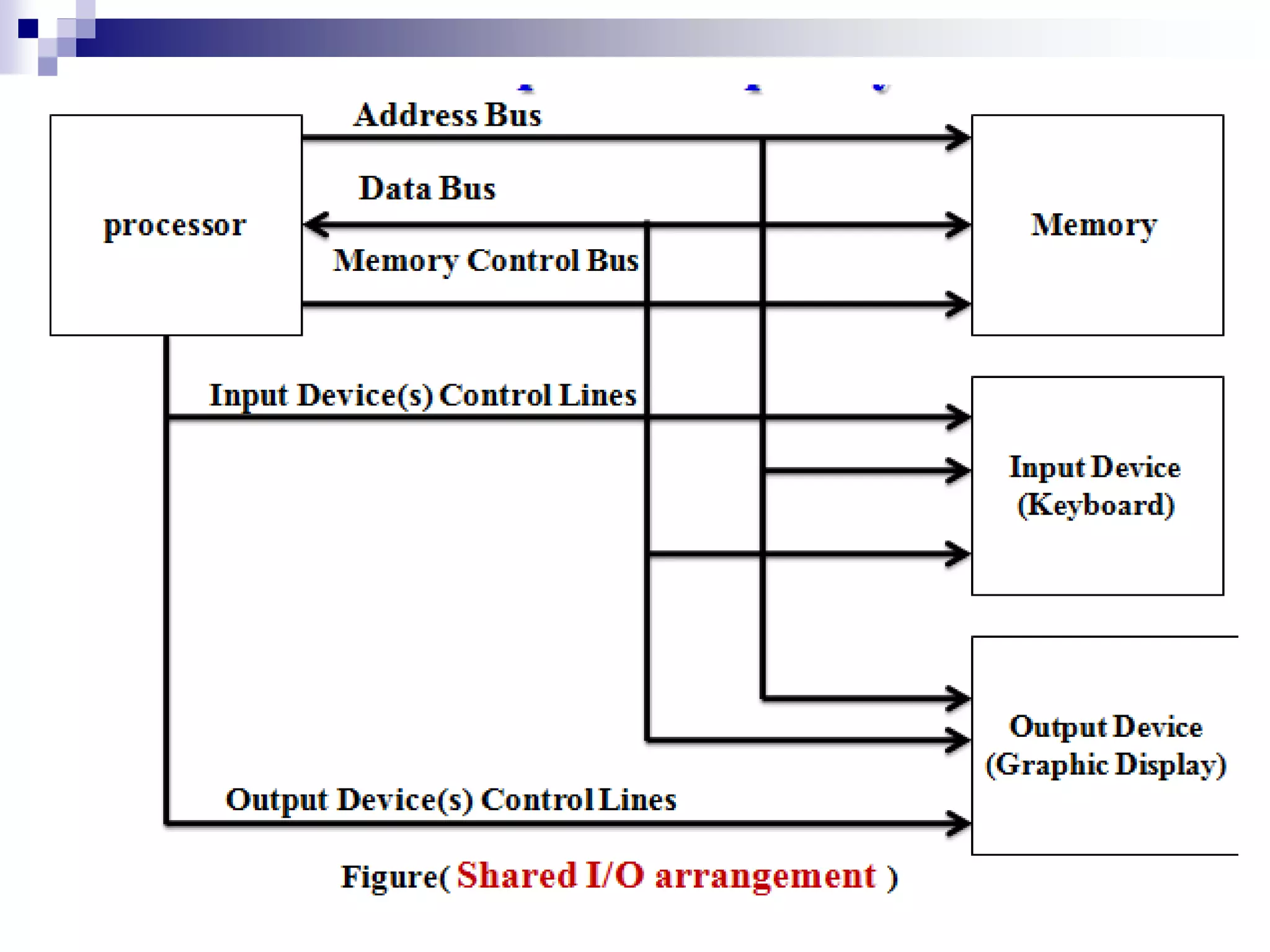
Input / OutputSystem There are two methods in which the Processor can address the input/output devices: In the First arrangement, I/O devices are assigned particular addresses, isolated from the address space assigned to the memory . The execution of an input instruction at an input device address will cause the character stored in the input register of that device to be transferred to a specific register in the CPU. Similarly, the execution of an output instruction . This arrangement, called ”Shared I/O’’, in the case, the address and data lines from the CPU can be shared between the memory and I/O devices. A separate control line will have to be used. This is because of the need for executing input and output instruction.
20.
Input/ Output System Themain Advantage of the Shared I/O arrangement is the Separation between the memory address space and that of the I/O devices. Its main Disadvantage is the need to have special input and output instruction in the processor instruction set.
21.
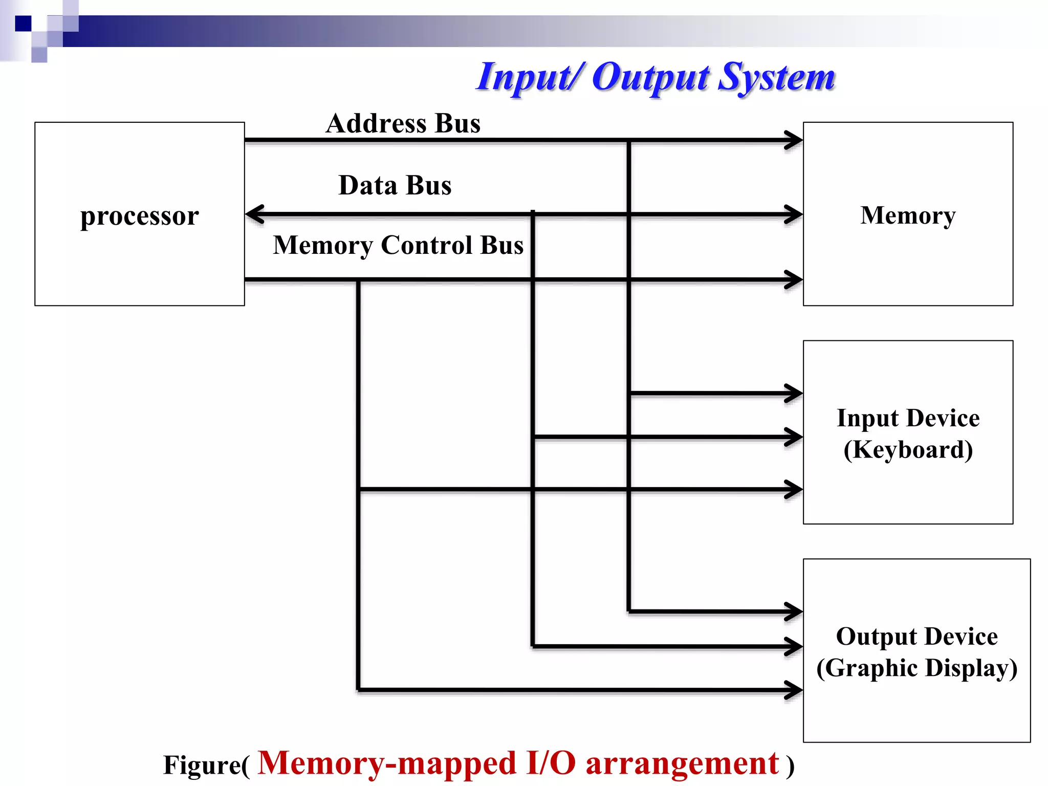
processor Memory Address Bus DataBus Memory Control Bus Figure( Memory-mapped I/O arrangement ) Output Device (Graphic Display) Input Device (Keyboard) Input/ Output System
22.
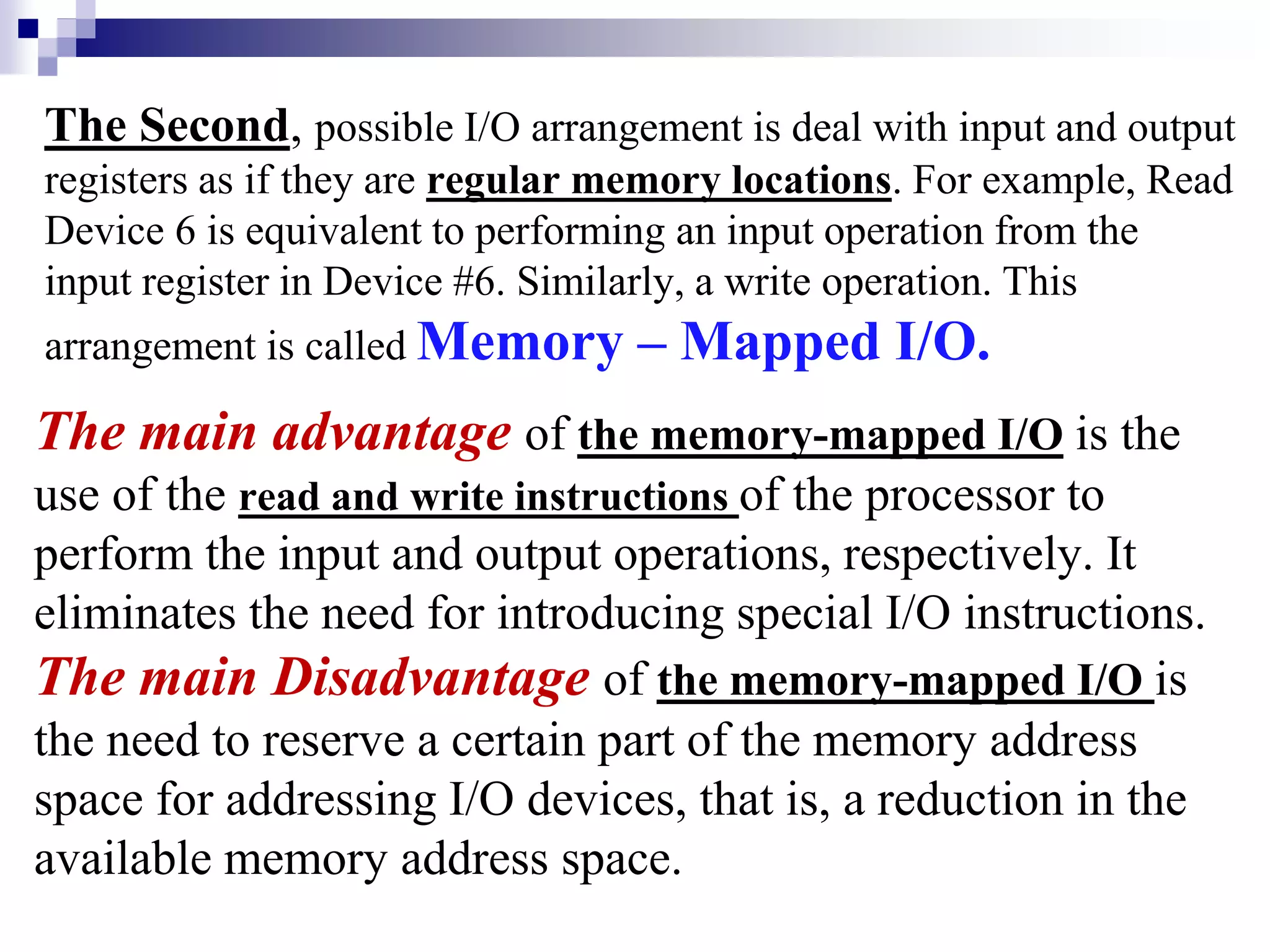
The Second, possibleI/O arrangement is deal with input and output registers as if they are regular memory locations. For example, Read Device 6 is equivalent to performing an input operation from the input register in Device #6. Similarly, a write operation. This arrangement is called Memory – Mapped I/O. The main advantage of the memory-mapped I/O is the use of the read and write instructions of the processor to perform the input and output operations, respectively. It eliminates the need for introducing special I/O instructions. The main Disadvantage of the memory-mapped I/O is the need to reserve a certain part of the memory address space for addressing I/O devices, that is, a reduction in the available memory address space.
23.
I/O Mapping Summary Memorymapped I/O Devices and memory share an address space. `I/O looks just like memory read/write No special commands for I/O Large selection of memory access commands available Isolated I/O Separate address spaces Need I/O or memory select lines Special commands for I/O Limited set
24.
Input Output Techniques ProgrammedI/O Programmed i/o refers to data transfers initiated by a (cpu) under driver software control to access registers or memory on a device. The cpu issues a command then waits for i/o operations to be complete. As the cpu is faster than the i/o module, the problem with programmed i/o is that the cpu has to wait along time for the i/o module of concern to be ready for either reception or transmission of data .the cpu, while waiting must repeatedly check the status of the i/o module, and this process is known as polling . As a result , the level of the performance of the entire system is severely degraded. Programmed i/o basically works in these ways :
25.
Programmed I/O -detail •CPU requests I/O operation. •I/O module performs operation. •I/O module sets status bits. •CPU checks status bits periodically. •I/O module does not inform CPU directly. •I/O module does not interrupt CPU. •CPU may wait or come back later.
26.
I/O Commands •CPU issuesaddress Identifies module (& device if >1 per module) •CPU issues command Control - telling module what to do e.g. spin up disk Test - check status e.g. power? Error? Read/Write Module transfers data via buffer from/to device
27.
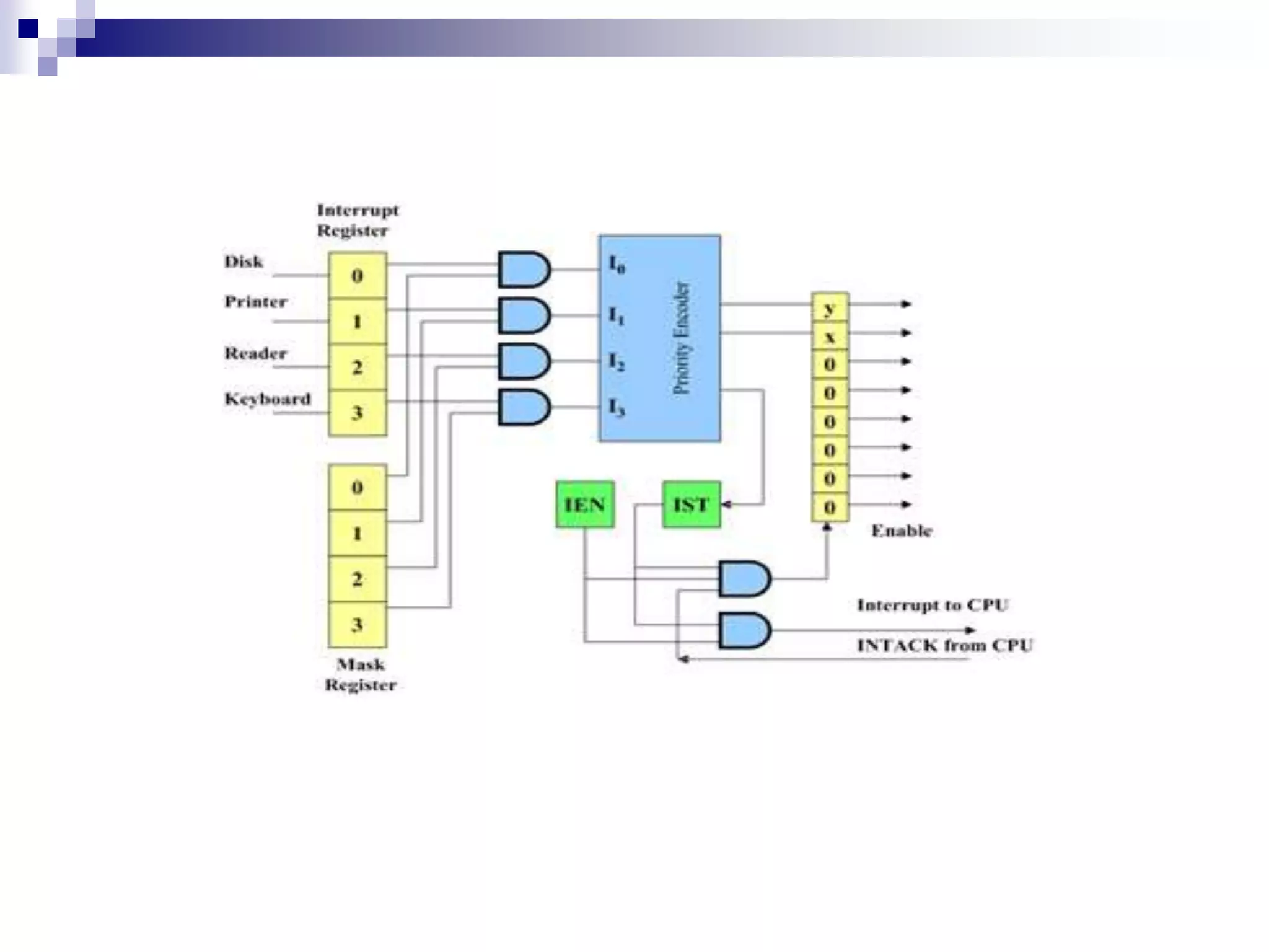
Interrupt Driven I/O TheCPU issues commands to the i/o module then proceeds with its normal work until interrupted by i/o device on completion of its work. For input, the device interrupts the cpu when new data has arrived and is ready to be arrived by the system processor . The actual actions to perform depend on whether the device uses i/o ports, memory mapping. For output, the deice delivers an interrupt either when it is ready to accept new data or to acknowledge asuccessful data transfer. Memory mapped and DMA- capable device usualy generate interrupt to tell the system they are done with the buffer . although interrupt relieves the cpu of having to waite for the device, but it is still inefficient in data transfer of large amount because the cpu has to transfer the data word by word between i/o module and memory . Below are the basic operations of interrupt. .
28.
Interrupt Driven I/O BasicOperation •CPU issues read command. •I/O module gets data from peripheral whilst CPU does other work. •I/O module interrupts CPU. •CPU requests data. •I/O module transfers data.
29.
Types of Interrupts HardwareInterrupts: If the signal for the processor is from external device or hardware is called hardware interrupts. Example: from keyboard we will press the key to do some action this pressing of key in keyboard will generate a signal which is given to the processor to do action, such interrupts are called hardware interrupts. Hardware interrupts can be classified into two types they are: •Maskable Interrupt: The hardware interrupts which can be delayed when a much highest priority interrupt has occurred to the processor. •Non Maskable Interrupt: The hardware which cannot be delayed and should process by the processor immediately.
30.
Software Interrupts: Softwareinterrupt can also divided in :to two types. They are •Normal Interrupts: the interrupts which are caused by the software instructions are called software instructions. •Exception: unplanned interrupts while executing a program is called Exception. For example: while executing a program if we got a value which should be divided by zero is called a exception.
31.
Design Issues How doyou identify the module issuing the interrupt? How do you deal with multiple interrupts? i.e. an interrupt handler being interrupted Identifying Interrupting Module (1) Different line for each module. PC Limits number of devices. Software poll. CPU asks each module in turn Slow
32.
Identifying Interrupting Module(2) •Daisy Chain or Hardware poll -Interrupt Acknowledge sent down a chain -Module responsible places vector on bus -CPU uses vector to identify handler routine •Bus Master Module must claim the bus before it can raise interrupt e.g. PCI & SCSI
34.
Direct Memory Access(DMA) Direct Memory Access (DMA) means CPU grants I/O module authority to read from or write to memory without involvement DMA module controls exchange of data between main memory and the I/O device. Because of DMA device can transfer data directly to and from memory, rather than using the CPU as an intermediary, and can thus relieve congestion on the bus. CPU is only involved at the beginning and end of the transfer and interrupted only after entire block has been transferred . Direct Memory Access needs a special hardware called DMA controller (DMAC) that manages the data transfers and arbitrates access to the system bus. The controllers are programmed with source and destination pointers (where to read/write the data), counters to track the number of transferred bytes, and settings, which includes I/O and memory types, interrupts and states for the CPU cycles.DMA increases system concurrency by allowing the CPU to perform tasks while the DMA system transfers data via the system and memory busses. Hardware design is complicated because the DMA controller must be integrated into the system, and the system must allow the DMA controller to be a bus master. Cycle stealing may also be necessary to allow the CPU and DMA controller to share use of the memory bus.
35.
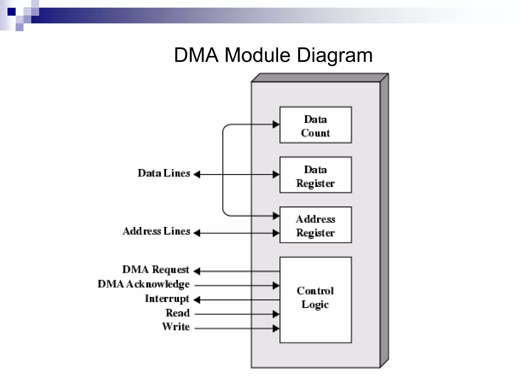
DMA controller DMA controllerhas an address register, data count register, control logic. address register :contaains an address that specifies the memory location of the data to be transferred. The DMA controller automatically increment the address register after each word transfere, so the transfere will be from the next memory location. data count register:holds the number of words to be transfere ,the word count is decremented by one after each word transfere . control logic:specifies the transfere mode ( number of DMA operation they spport).
36.
DMA transfer types: -Burstmode the DMA controller keeps control of the bus until all the data has been transferred to (from ) memory from (to) the peripheral device. This mode of transfere is nneeded for fast devices where data transfere cannot be stopped until the entir transfer is done .
37.
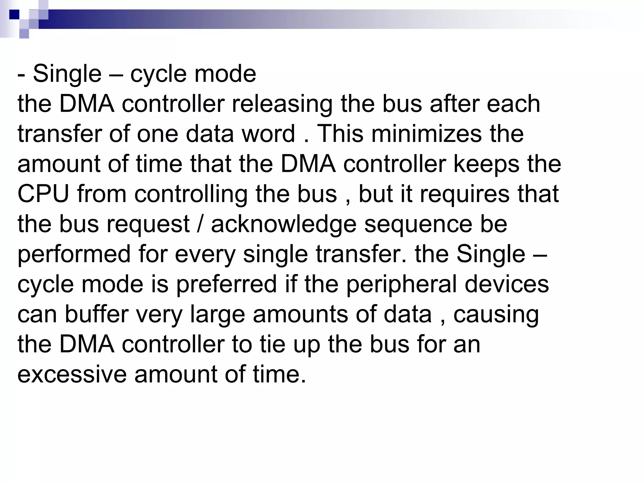
- Single –cycle mode the DMA controller releasing the bus after each transfer of one data word . This minimizes the amount of time that the DMA controller keeps the CPU from controlling the bus , but it requires that the bus request / acknowledge sequence be performed for every single transfer. the Single – cycle mode is preferred if the peripheral devices can buffer very large amounts of data , causing the DMA controller to tie up the bus for an excessive amount of time.
DMA Operation CPU carrieson with other work. CPU tells DMA controller. Read/Write. Device address. Starting address of memory block for data. Amount of data to be transferred. DMA controller deals with transfer. DMA controller sends interrupt when finished.
40.
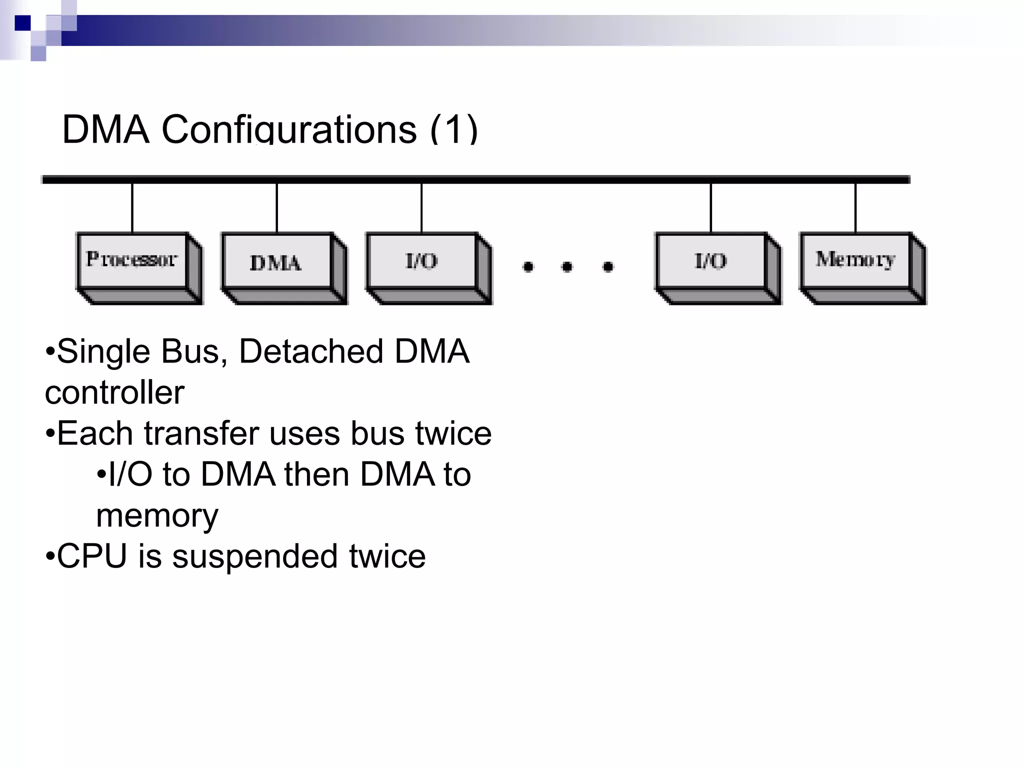
DMA Configurations (1) •SingleBus, Detached DMA controller •Each transfer uses bus twice •I/O to DMA then DMA to memory •CPU is suspended twice
41.
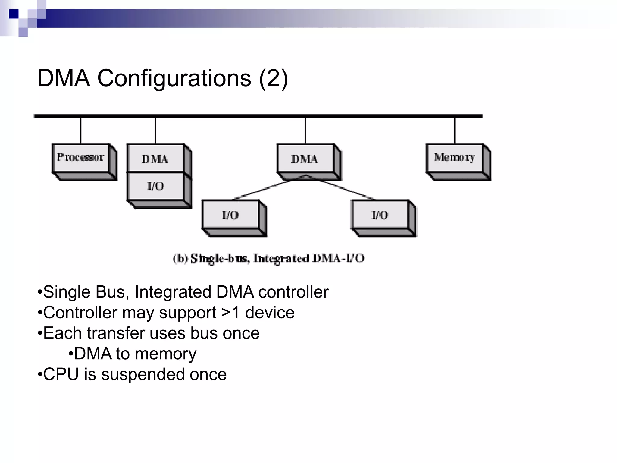
DMA Configurations (2) •SingleBus, Integrated DMA controller •Controller may support >1 device •Each transfer uses bus once •DMA to memory •CPU is suspended once
42.
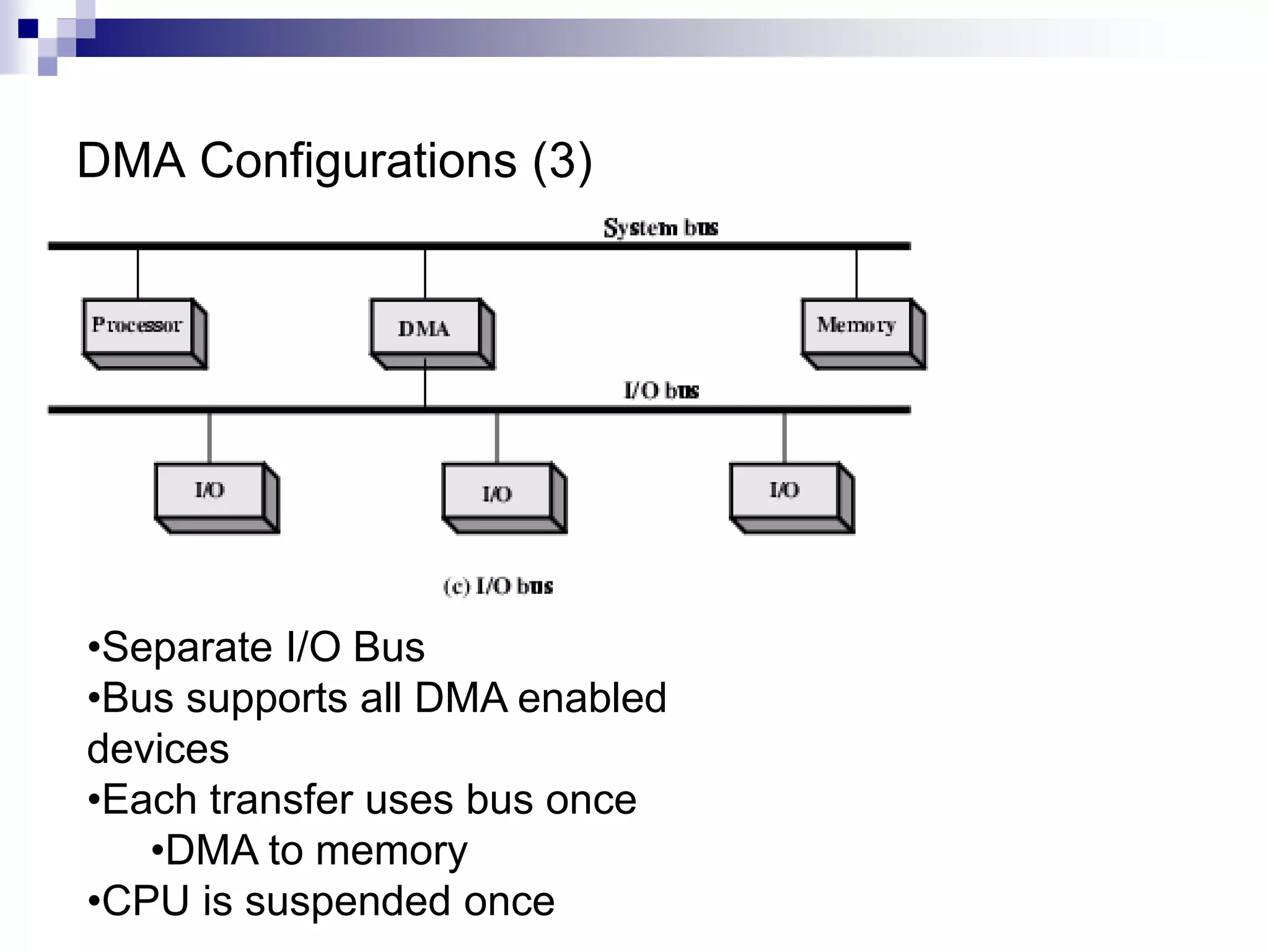
DMA Configurations (3) •SeparateI/O Bus •Bus supports all DMA enabled devices •Each transfer uses bus once •DMA to memory •CPU is suspended once