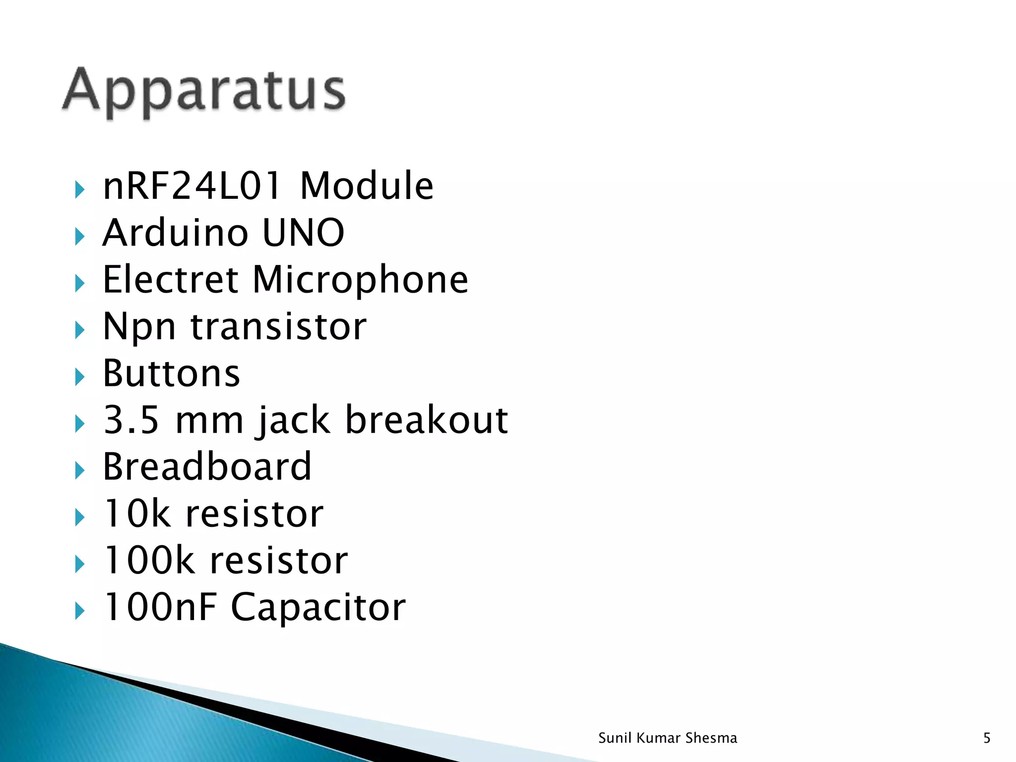
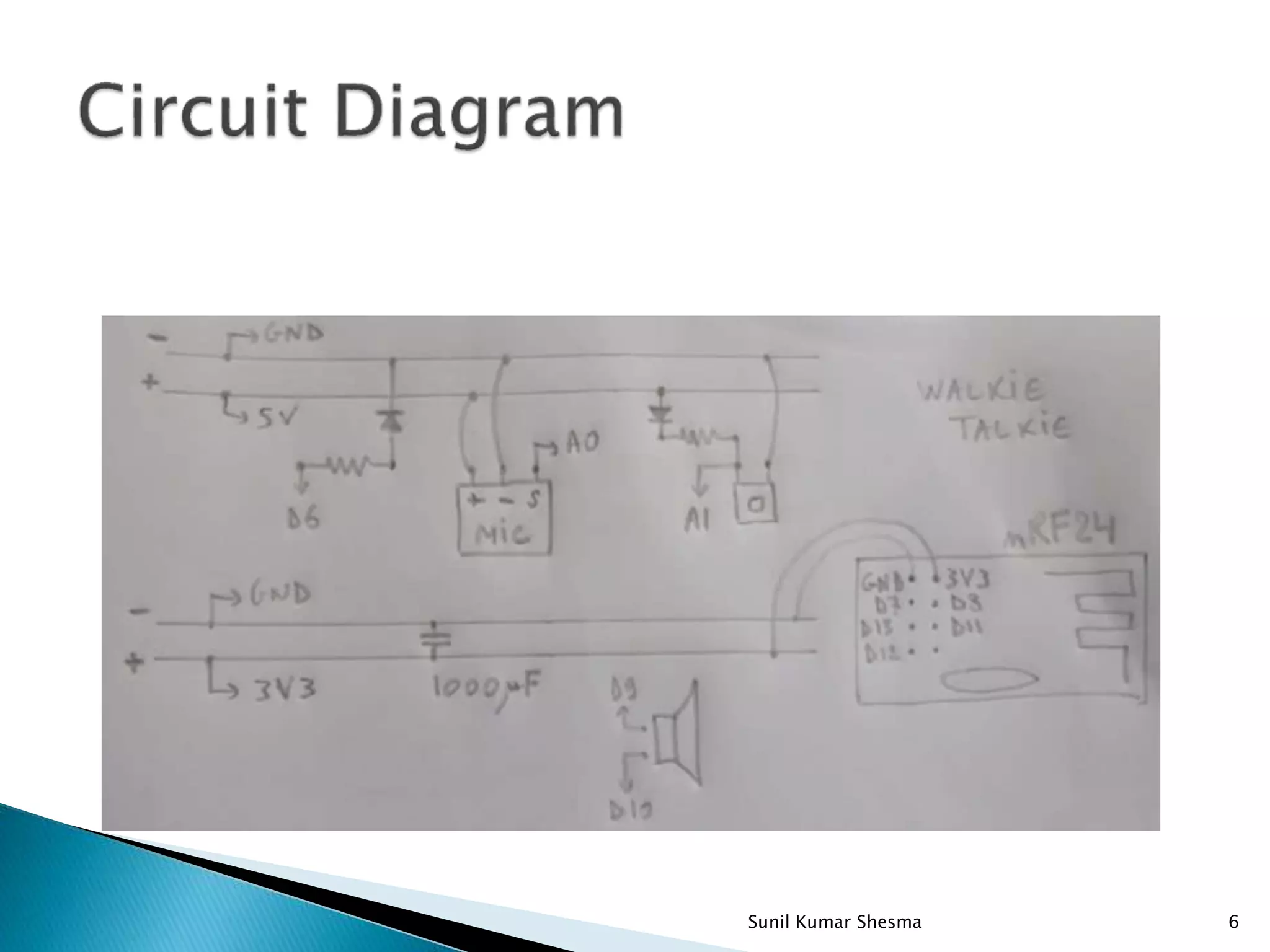
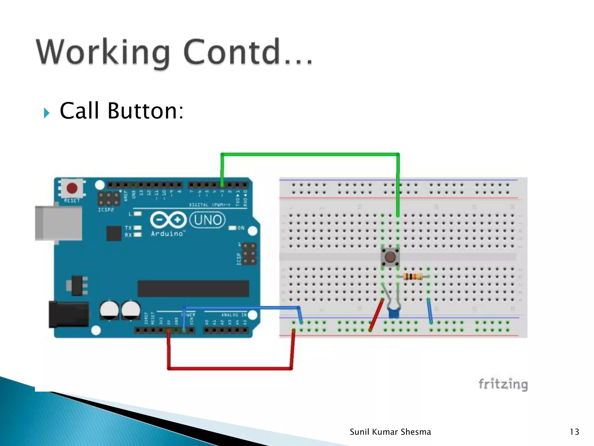
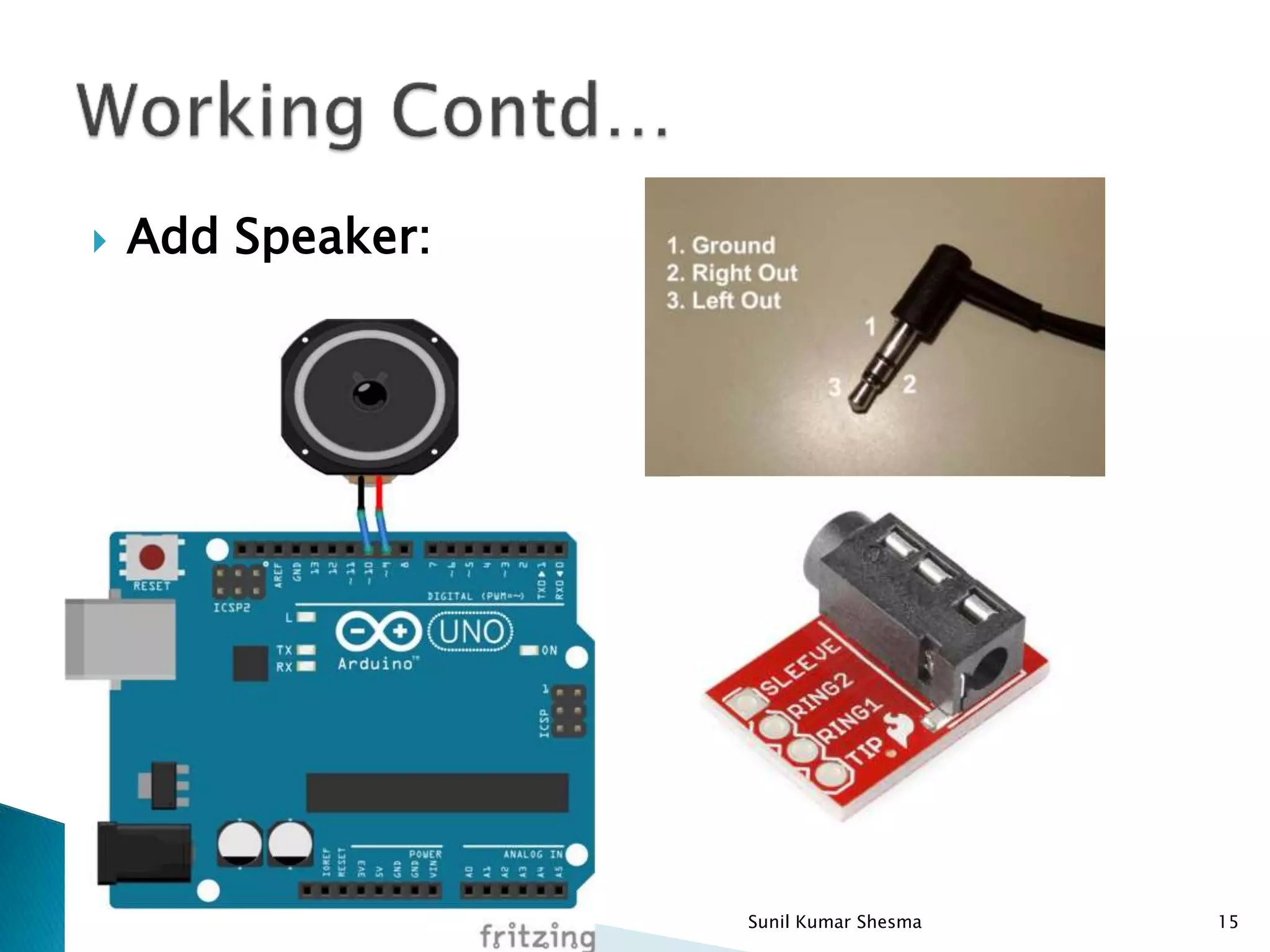
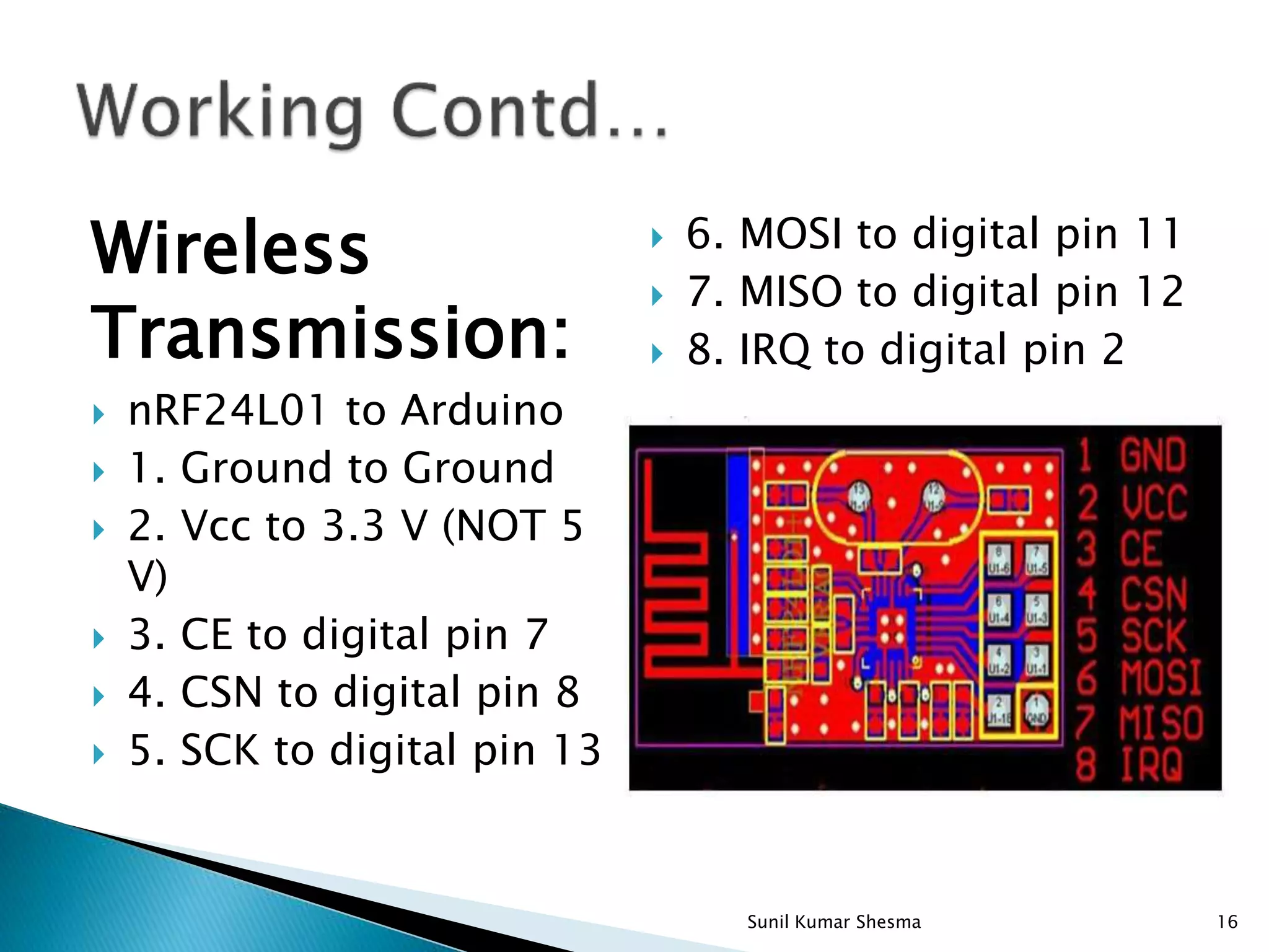
Communication System 1Sunil Kumar Shesma
 Introduction  Apparatus  Circuit Diagram  Technical Details  Technical Specifications  Working  Conclusion  References 2Sunil Kumar Shesma
 A transceiver is using transmit the signal as well as receive the signal.  It is a device comprising both a transmitter and a receiver that are combined and share common circuitry or a single housing. When no circuitry is common between transmit and receive functions, the Device is a transmitter- receiver.  It is a Wireless Digital Audio Streaming Realtime with Arduino and nrf24L01 module based project. 3Sunil Kumar Shesma
 nrf24L01 module is highly integrated, ultra low power(ULP),2Mbps RF transceiver IC for the 2.4Ghz ISM(Industrial, Scientific and Medical) band.  In this project, We are using transmitting the voice signal using nRF24L01 module in following conditions: 1.Normal Condition 2.Ab-normal Condition(With interrupt input signal) 4Sunil Kumar Shesma
 nRF24L01 Module  Arduino UNO  Electret Microphone  Npn transistor  Buttons  3.5 mm jack breakout  Breadboard  10k resistor  100k resistor  100nF Capacitor 5Sunil Kumar Shesma
6Sunil Kumar Shesma
 nRF24L01 Module: The nRF24L01 is a single chip 2.4GHz transceiver with an embedded baseband protocol engine designed for ultra low power wireless applications. An MCU (microcontroller) and very few external passive components are needed to design a radio system with the nRF24L01. 7Sunil Kumar Shesma
 Arduino UNO: The Arduino Uno is a microcontroller board based on the ATmega328 (datasheet). It contains everything needed to support the microcontroller; simply connect it to a computer with a USB cable or power it with a AC-to-DC adapter or battery to get started. 8Sunil Kumar Shesma
 nRF24L01: Transmitter Programmable output power: 0, -6, -12 or -18dBm 11.3mA at 0dBm output power Receiver Integrated channel filters 12.3mA at 2Mbps -82dBm sensitivity at 2Mbps -85dBm sensitivity at 1Mbps Programmable LNA gain 9Sunil Kumar Shesma
 Microcontroller ATmega 328  Operating Voltage 5V  Input Voltage (recommended) 7- 12V  Input Voltage (limits) 6-20V  Digital I/O Pins 14 (of which 6 provide PWM output)  Analog Input Pins 6  DC Current per I/O Pin 40 mA  DC Current for 3.3V Pin 50 mA  Flash Memory 32 KB of which 0.5 KB used by bootloader 10Sunil Kumar Shesma
 Gathers the tools  Microphone Circuit  Call Button  Add Speaker  Wireless transmission  Ardiuno Code 11Sunil Kumar Shesma
Microphone Circuit : it will produce an AC current at the base of the transistor based upon the sound wave hitting the microphone. The base current of the transistor is amplified and so we have an amplified sound wave that we are feeding into our microcontroller. 12Sunil Kumar Shesma
 Call Button: 13Sunil Kumar Shesma
Call Button: Here we have used a simple pushbutton,10 k resistor, and a 100 nF capacitor.  With this piece of code, we go to the "talk()" function which checks the voltage on pin 3.  If the voltage is HIGH or 5 V, the nRF24L01 will switch to transmit mode (sending voice). If the voltage is LOW or 0 V, the nRF24L01 will switch to receive mode (receiving voice). The voltage on pin 3 should be HIGH when the button is pressed and LOW when the button is released.  Whenever the voltage on pin 3 "CHANGES" as denoted in our "attachInterrupt" function, the "talk()“ function will execute. 14Sunil Kumar Shesma
 Add Speaker: 15Sunil Kumar Shesma
Wireless Transmission:  nRF24L01 to Arduino  1. Ground to Ground  2. Vcc to 3.3 V (NOT 5 V)  3. CE to digital pin 7  4. CSN to digital pin 8  5. SCK to digital pin 13  6. MOSI to digital pin 11  7. MISO to digital pin 12  8. IRQ to digital pin 2 16Sunil Kumar Shesma
 Ardiuno Code:  We put together a simple code utilizing the RF24 and RF24Audio libraries.  Upload this code to both Arduinos. Both circuits with default to "receive“ at the start of the code. Press the "call button" to transmit audio from one radio to the other.  Remark: The RF24Audio is using PWM and some other techniques to transmit audio. 17Sunil Kumar Shesma
 With the help of our transeceiver module, we can transmit the voice signals upto 100meters.  Here, For getting less interrupt we can use the less bandwidth low pass filter. 18Sunil Kumar Shesma
 https://www.google.co.in/url?sa=t&source=web&r ct=j&url=http://www.instructables.com/id/Wristwa tch- WalkieTalkie/&ved=0ahUKEwi6lKyu_63SAhUDULwK HYv8AfsQFggZMAA&usg=AFQjCNESRlVxZZhszA- GlmmVLPyyF7QE7Q&sig2=GZSeTZkyUUciXraVuVcA GQ  https://hackaday.io/project/8598-wristwatch- walkie-talkie  http://cassiopeia.hk/walkietalkie/ 19Sunil Kumar Shesma
Thanking you 20Sunil Kumar Shesma

Wireless transmission of voice signal using nRF24L01 module

  • 1.
  • 2.
     Introduction  Apparatus Circuit Diagram  Technical Details  Technical Specifications  Working  Conclusion  References 2Sunil Kumar Shesma
  • 3.
     A transceiveris using transmit the signal as well as receive the signal.  It is a device comprising both a transmitter and a receiver that are combined and share common circuitry or a single housing. When no circuitry is common between transmit and receive functions, the Device is a transmitter- receiver.  It is a Wireless Digital Audio Streaming Realtime with Arduino and nrf24L01 module based project. 3Sunil Kumar Shesma
  • 4.
     nrf24L01 moduleis highly integrated, ultra low power(ULP),2Mbps RF transceiver IC for the 2.4Ghz ISM(Industrial, Scientific and Medical) band.  In this project, We are using transmitting the voice signal using nRF24L01 module in following conditions: 1.Normal Condition 2.Ab-normal Condition(With interrupt input signal) 4Sunil Kumar Shesma
  • 5.
     nRF24L01 Module Arduino UNO  Electret Microphone  Npn transistor  Buttons  3.5 mm jack breakout  Breadboard  10k resistor  100k resistor  100nF Capacitor 5Sunil Kumar Shesma
  • 6.
  • 7.
     nRF24L01 Module: ThenRF24L01 is a single chip 2.4GHz transceiver with an embedded baseband protocol engine designed for ultra low power wireless applications. An MCU (microcontroller) and very few external passive components are needed to design a radio system with the nRF24L01. 7Sunil Kumar Shesma
  • 8.
     Arduino UNO: TheArduino Uno is a microcontroller board based on the ATmega328 (datasheet). It contains everything needed to support the microcontroller; simply connect it to a computer with a USB cable or power it with a AC-to-DC adapter or battery to get started. 8Sunil Kumar Shesma
  • 9.
     nRF24L01: Transmitter Programmable outputpower: 0, -6, -12 or -18dBm 11.3mA at 0dBm output power Receiver Integrated channel filters 12.3mA at 2Mbps -82dBm sensitivity at 2Mbps -85dBm sensitivity at 1Mbps Programmable LNA gain 9Sunil Kumar Shesma
  • 10.
     Microcontroller ATmega 328 Operating Voltage 5V  Input Voltage (recommended) 7- 12V  Input Voltage (limits) 6-20V  Digital I/O Pins 14 (of which 6 provide PWM output)  Analog Input Pins 6  DC Current per I/O Pin 40 mA  DC Current for 3.3V Pin 50 mA  Flash Memory 32 KB of which 0.5 KB used by bootloader 10Sunil Kumar Shesma
  • 11.
     Gathers thetools  Microphone Circuit  Call Button  Add Speaker  Wireless transmission  Ardiuno Code 11Sunil Kumar Shesma
  • 12.
    Microphone Circuit : itwill produce an AC current at the base of the transistor based upon the sound wave hitting the microphone. The base current of the transistor is amplified and so we have an amplified sound wave that we are feeding into our microcontroller. 12Sunil Kumar Shesma
  • 13.
  • 14.
    Call Button: Here wehave used a simple pushbutton,10 k resistor, and a 100 nF capacitor.  With this piece of code, we go to the "talk()" function which checks the voltage on pin 3.  If the voltage is HIGH or 5 V, the nRF24L01 will switch to transmit mode (sending voice). If the voltage is LOW or 0 V, the nRF24L01 will switch to receive mode (receiving voice). The voltage on pin 3 should be HIGH when the button is pressed and LOW when the button is released.  Whenever the voltage on pin 3 "CHANGES" as denoted in our "attachInterrupt" function, the "talk()“ function will execute. 14Sunil Kumar Shesma
  • 15.
  • 16.
    Wireless Transmission:  nRF24L01 toArduino  1. Ground to Ground  2. Vcc to 3.3 V (NOT 5 V)  3. CE to digital pin 7  4. CSN to digital pin 8  5. SCK to digital pin 13  6. MOSI to digital pin 11  7. MISO to digital pin 12  8. IRQ to digital pin 2 16Sunil Kumar Shesma
  • 17.
     Ardiuno Code: We put together a simple code utilizing the RF24 and RF24Audio libraries.  Upload this code to both Arduinos. Both circuits with default to "receive“ at the start of the code. Press the "call button" to transmit audio from one radio to the other.  Remark: The RF24Audio is using PWM and some other techniques to transmit audio. 17Sunil Kumar Shesma
  • 18.
     With thehelp of our transeceiver module, we can transmit the voice signals upto 100meters.  Here, For getting less interrupt we can use the less bandwidth low pass filter. 18Sunil Kumar Shesma
  • 19.
  • 20.