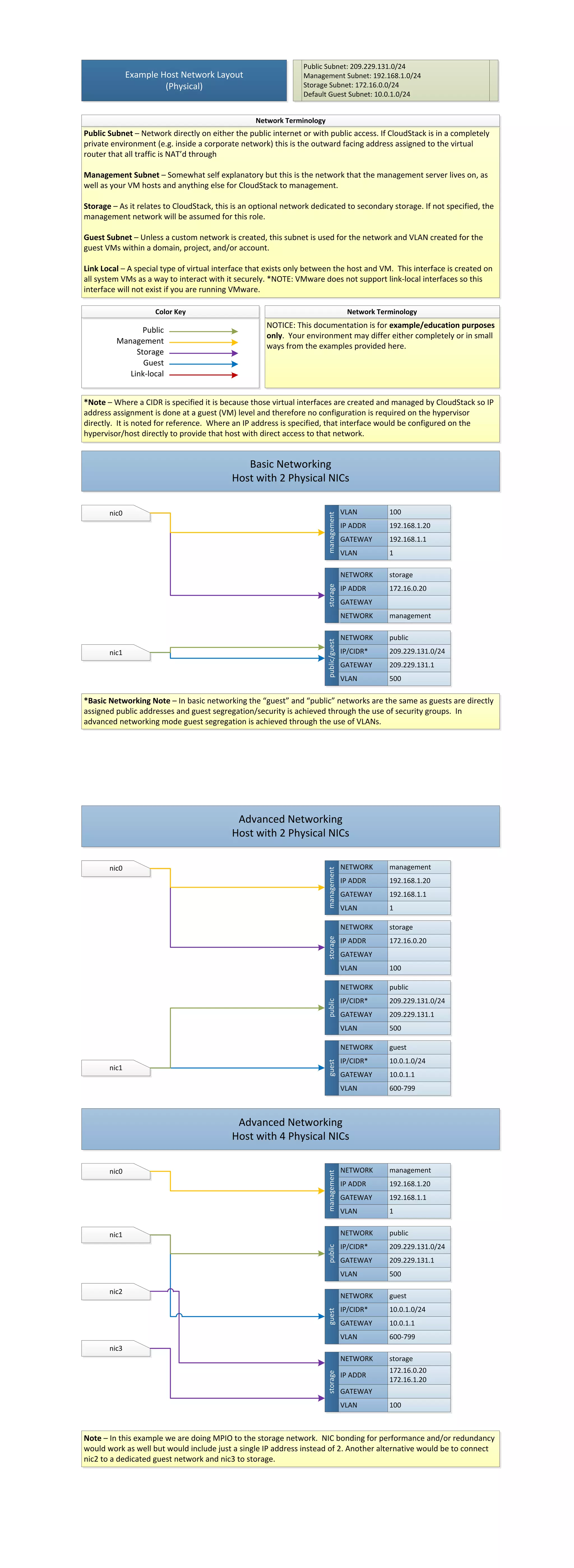
Public Subnet: 209.229.131.0/24 Example Host Network Layout Management Subnet: 192.168.1.0/24 (Physical) Storage Subnet: 172.16.0.0/24 Default Guest Subnet: 10.0.1.0/24 Network Terminology Public Subnet – Network directly on either the public internet or with public access. If CloudStack is in a completely private environment (e.g. inside a corporate network) this is the outward facing address assigned to the virtual router that all traffic is NAT’d through Management Subnet – Somewhat self explanatory but this is the network that the management server lives on, as well as your VM hosts and anything else for CloudStack to management. Storage – As it relates to CloudStack, this is an optional network dedicated to secondary storage. If not specified, the management network will be assumed for this role. Guest Subnet – Unless a custom network is created, this subnet is used for the network and VLAN created for the guest VMs within a domain, project, and/or account. Link Local – A special type of virtual interface that exists only between the host and VM. This interface is created on all system VMs as a way to interact with it securely. *NOTE: VMware does not support link-local interfaces so this interface will not exist if you are running VMware. Color Key Network Terminology NOTICE: This documentation is for example/education purposes Public only. Your environment may differ either completely or in small Management ways from the examples provided here. Storage Guest Link-local *Note – Where a CIDR is specified it is because those virtual interfaces are created and managed by CloudStack so IP address assignment is done at a guest (VM) level and therefore no configuration is required on the hypervisor directly. It is noted for reference. Where an IP address is specified, that interface would be configured on the hypervisor/host directly to provide that host with direct access to that network. Basic Networking Host with 2 Physical NICs nic0 VLAN 100 management IP ADDR 192.168.1.20 GATEWAY 192.168.1.1 VLAN 1 NETWORK storage storage IP ADDR 172.16.0.20 GATEWAY NETWORK management NETWORK public public/guest nic1 IP/CIDR* 209.229.131.0/24 GATEWAY 209.229.131.1 VLAN 500 *Basic Networking Note – In basic networking the “guest” and “public” networks are the same as guests are directly assigned public addresses and guest segregation/security is achieved through the use of security groups. In advanced networking mode guest segregation is achieved through the use of VLANs. Advanced Networking Host with 2 Physical NICs nic0 NETWORK management management IP ADDR 192.168.1.20 GATEWAY 192.168.1.1 VLAN 1 NETWORK storage storage IP ADDR 172.16.0.20 GATEWAY VLAN 100 NETWORK public IP/CIDR* 209.229.131.0/24 public GATEWAY 209.229.131.1 VLAN 500 NETWORK guest IP/CIDR* 10.0.1.0/24 guest nic1 GATEWAY 10.0.1.1 VLAN 600-799 Advanced Networking Host with 4 Physical NICs nic0 NETWORK management management IP ADDR 192.168.1.20 GATEWAY 192.168.1.1 VLAN 1 nic1 NETWORK public IP/CIDR* 209.229.131.0/24 public GATEWAY 209.229.131.1 VLAN 500 nic2 NETWORK guest IP/CIDR* 10.0.1.0/24 guest GATEWAY 10.0.1.1 VLAN 600-799 nic3 NETWORK storage 172.16.0.20 storage IP ADDR 172.16.1.20 GATEWAY VLAN 100 Note – In this example we are doing MPIO to the storage network. NIC bonding for performance and/or redundancy would work as well but would include just a single IP address instead of 2. Another alternative would be to connect nic2 to a dedicated guest network and nic3 to storage.

Cloudstack example host networking

  • 1.
    Public Subnet: 209.229.131.0/24 Example Host Network Layout Management Subnet: 192.168.1.0/24 (Physical) Storage Subnet: 172.16.0.0/24 Default Guest Subnet: 10.0.1.0/24 Network Terminology Public Subnet – Network directly on either the public internet or with public access. If CloudStack is in a completely private environment (e.g. inside a corporate network) this is the outward facing address assigned to the virtual router that all traffic is NAT’d through Management Subnet – Somewhat self explanatory but this is the network that the management server lives on, as well as your VM hosts and anything else for CloudStack to management. Storage – As it relates to CloudStack, this is an optional network dedicated to secondary storage. If not specified, the management network will be assumed for this role. Guest Subnet – Unless a custom network is created, this subnet is used for the network and VLAN created for the guest VMs within a domain, project, and/or account. Link Local – A special type of virtual interface that exists only between the host and VM. This interface is created on all system VMs as a way to interact with it securely. *NOTE: VMware does not support link-local interfaces so this interface will not exist if you are running VMware. Color Key Network Terminology NOTICE: This documentation is for example/education purposes Public only. Your environment may differ either completely or in small Management ways from the examples provided here. Storage Guest Link-local *Note – Where a CIDR is specified it is because those virtual interfaces are created and managed by CloudStack so IP address assignment is done at a guest (VM) level and therefore no configuration is required on the hypervisor directly. It is noted for reference. Where an IP address is specified, that interface would be configured on the hypervisor/host directly to provide that host with direct access to that network. Basic Networking Host with 2 Physical NICs nic0 VLAN 100 management IP ADDR 192.168.1.20 GATEWAY 192.168.1.1 VLAN 1 NETWORK storage storage IP ADDR 172.16.0.20 GATEWAY NETWORK management NETWORK public public/guest nic1 IP/CIDR* 209.229.131.0/24 GATEWAY 209.229.131.1 VLAN 500 *Basic Networking Note – In basic networking the “guest” and “public” networks are the same as guests are directly assigned public addresses and guest segregation/security is achieved through the use of security groups. In advanced networking mode guest segregation is achieved through the use of VLANs. Advanced Networking Host with 2 Physical NICs nic0 NETWORK management management IP ADDR 192.168.1.20 GATEWAY 192.168.1.1 VLAN 1 NETWORK storage storage IP ADDR 172.16.0.20 GATEWAY VLAN 100 NETWORK public IP/CIDR* 209.229.131.0/24 public GATEWAY 209.229.131.1 VLAN 500 NETWORK guest IP/CIDR* 10.0.1.0/24 guest nic1 GATEWAY 10.0.1.1 VLAN 600-799 Advanced Networking Host with 4 Physical NICs nic0 NETWORK management management IP ADDR 192.168.1.20 GATEWAY 192.168.1.1 VLAN 1 nic1 NETWORK public IP/CIDR* 209.229.131.0/24 public GATEWAY 209.229.131.1 VLAN 500 nic2 NETWORK guest IP/CIDR* 10.0.1.0/24 guest GATEWAY 10.0.1.1 VLAN 600-799 nic3 NETWORK storage 172.16.0.20 storage IP ADDR 172.16.1.20 GATEWAY VLAN 100 Note – In this example we are doing MPIO to the storage network. NIC bonding for performance and/or redundancy would work as well but would include just a single IP address instead of 2. Another alternative would be to connect nic2 to a dedicated guest network and nic3 to storage.