The document presents a project report on an automatic railway gate control system developed using Arduino Uno, aiming to enhance safety at level crossings by replacing manual gate control with an automatic mechanism. The system utilizes infrared sensors to detect train arrivals and departures, triggering servo or DC motors to operate the gate while buzzer alerts are provided for pedestrians. The proposed model emphasizes reliability, cost-efficiency, and the potential to significantly reduce accidents at unmanned crossings in India.
Automatic Railway GateControl Using Arduino Uno A PROJECT REPORT Submitted by T.SELVALAKSHMI A comprehensive project report has been submitted in partial fulfillment of the requirements for the degree of Bachelor of Technology In ELECTRONICS & COMMUNICATION ENGINEERING DR.G.U.POPE COLLEGE OF ENGINEERING, SAWYARPURAM
2.
Abstract: As Human safetyis major goal for Railways. The intention of this of paper is to achieve automatic control at the level crossings when the arrival/departure of the train takes place replacing the manual gate control. The railway gate automatically is closed when a train passes through the railway crossing. The detection of arrival and departure of train is donebyusing two IR sensors. Thegate opening and closing is to be done using servo motors/DC motors which is controlled by Arduino Uno. Buzzers are used to indicate the closing of gate for the people who are trying to cross the gate. This system helps in avoiding the increased number of the accidents at level crossing in India. The hardware is supported by the Arduino C programming. The proposed system is more reliable and cost efficient.
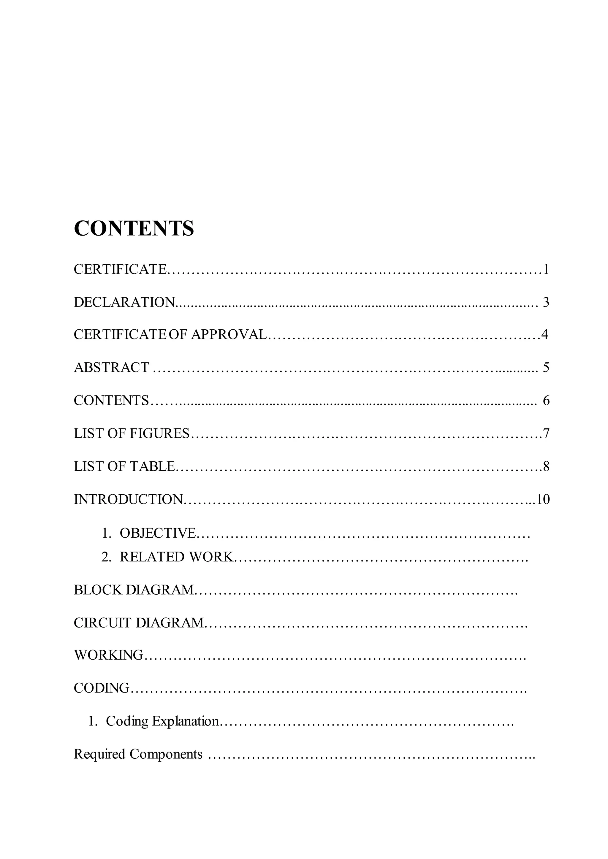
Description of Components……………………………………………………… 1.Arduino Uno……………………………………………………… 2. H-Bridge Motor Driver……………………………………………… 3. IR Sensor Module……………………………………………… 4. DC Motor……………………………………………… 5. Battery……………………………………………… 6. Software……………………………………………… FUTURE SCOPE………………………………………………………………. 1. Possible obstacles ……………………………………………… 2. Possible solutions and future scopes ADVANTAGES……………………………………………… PROBLEMS ……………………………………………… DISCUSSION……………………………………………… APPLICATIONS……………………………………………… CONCLUSION ……………………………………………… COST ANALISIS………………………………………………
5.
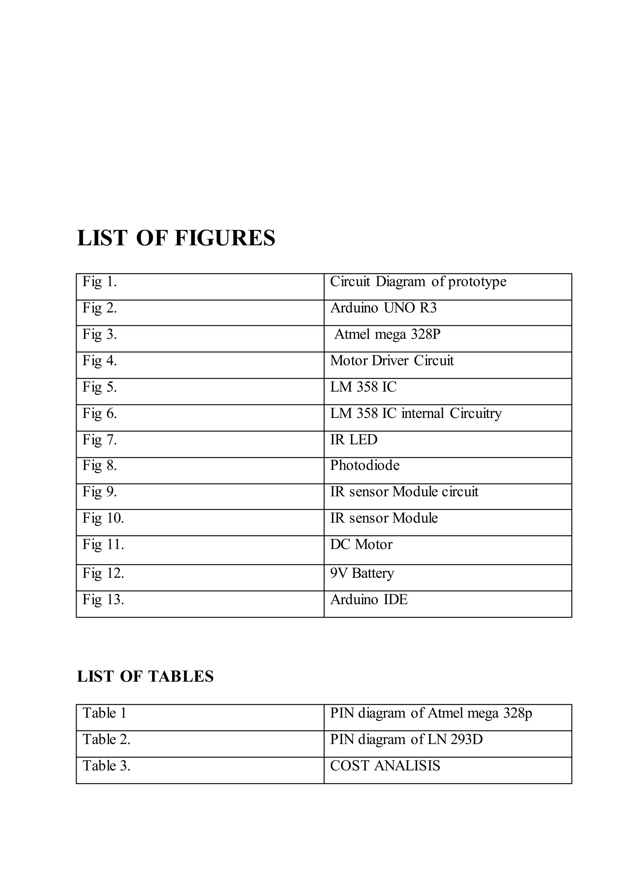
LIST OF FIGURES Fig1. Circuit Diagram of prototype Fig 2. Arduino UNO R3 Fig 3. Atmel mega 328P Fig 4. Motor Driver Circuit Fig 5. LM 358 IC Fig 6. LM 358 IC internal Circuitry Fig 7. IR LED Fig 8. Photodiode Fig 9. IR sensor Module circuit Fig 10. IR sensor Module Fig 11. DC Motor Fig 12. 9V Battery Fig 13. Arduino IDE LIST OF TABLES Table 1 PIN diagram of Atmel mega 328p Table 2. PIN diagram of LN 293D Table 3. COST ANALISIS
6.
INTRODUCTION In today’s scenarioRailway safety becomes the most important aspect of railways all over the world. As we know the Railways is the cheapest modeof transportation, and due to manual operation, accidents are likely to happen. There are 30348 level crossings on Indian Railways across the country.18785 are man handled and 11563 are non-man handled level crossings out of 303048 level crossings. To avoid accidents over previous five years 4792 level crossings have been removed by the respective Zonal railways of Indian Railways. The Indian ministry of Railways made a decision focusingon eliminating all level crossings onavailability ofrailway funds, which could be controlled automatically. The suggest system helps in achieving the safety and to prevent accidents at the level crossings that are non-man handled. The Automatic railway gate control system can be employed under non man handled level crossing where the chances of accidents are higher and requirement of reliable operation are there. Since, the proposed modelsuggests an automatic system, it helps in reducing the error which is in manual operation and it will beused as highly reliable source. Theproposedmodelofautomatic gate control at level crossings is highly economical based on the arrangement done by using Arduino and Servo motor/ DC motors which makes the design for use in almost every non man handled that is unmanned railway crossings. The proposed modelsuggests a design to control a railway level-crossing by servo motor/ DC motors using Arduino controller. The connection of motor is done from
7.
Arduino with thehelp of a motor driver for controlling the railway gate. Two IR sensors are used to detect arrival and departure of the train. IR sensors are checking the complete closing of gate. 1.Objective: The objective of this project is to create an automatic railway gate control system which can be implemented easily in roads. Generally there are manual gate control system which are maintained by person. As vehicles are increasing day by day it has become more difficult to control the gate manually. As a result often accident occurs and many people become injured badly and sometimes it become very serious when people died due to this type of accidents. This project can help us to reduce accidents in our country by introducing automatic railway gate control system. 2.Related work Earlier opening/closing of crossing gates were fully controlled by gatekeeper. The method was that when train departs from any station a controller or a station master was used to call to contact the gatekeeper and inform the gatekeeper about the departure. On receiving the message, the gatekeeper closes the gate by calculating the time from station to the gate. However, the gate remains closed for long time even if the train is late for some reasons. This can be eliminated by using an automatic railway gate control which uses a sensor near to the railway gate that detects the arrival of a train and closes the gate. Note this requires very less time compareto manual operation of the gates and reduces the manpower. The Proposed model to automatically control the crossing gateway helps in achieving the safety and to prevent accidents at the unmanned level crossings. The Automatic railway gate system can be employed in an unmanned level crossing where the chances of accidents are higher and reliable operation is required. Since, the proposed system
8.
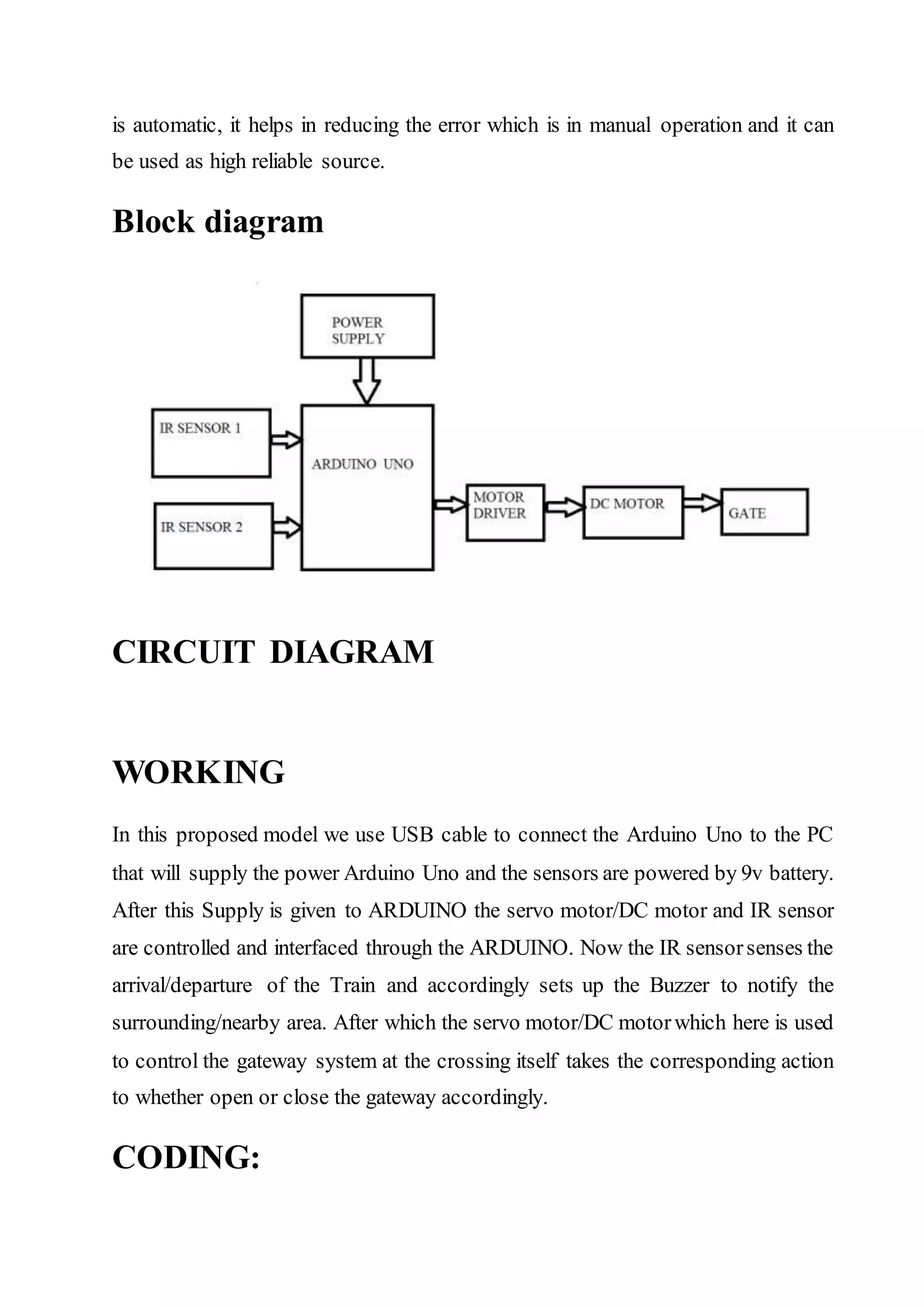
is automatic, ithelps in reducing the error which is in manual operation and it can be used as high reliable source. Block diagram CIRCUIT DIAGRAM WORKING In this proposed model we use USB cable to connect the Arduino Uno to the PC that will supply the power Arduino Uno and the sensors are powered by 9v battery. After this Supply is given to ARDUINO the servo motor/DC motor and IR sensor are controlled and interfaced through the ARDUINO. Now the IR sensorsenses the arrival/departure of the Train and accordingly sets up the Buzzer to notify the surrounding/nearby area. After which the servo motor/DC motorwhich here is used to control the gateway system at the crossing itself takes the corresponding action to whether open or close the gateway accordingly. CODING:
{ digitalWrite(8,HIGH); digitalWrite(9,LOW); } else { digitalWrite(8,LOW); digitalWrite(9,HIGH);// put yourmain code here, to run repeatedly: } } } Coding Explanation: First the pin mode for the appropriate pins in Arduino Uno. Set the pin 2 & 3 as a inputs and set the pin 8 & 9 as a outputs. Then enter into the loop and write the command. When the digitalRead to pin 2 is HIGH then it will HIGH the pin 8, else it check digitalRead to pin 3 if it is HIGH then it will also HIGH the pin 8, if the digitalRead to pin 2 and 3 both are LOW then it will HIGH the pin 9. Required Components 1. Arduino Uno R3 2. L293D motor driver 3. Lm 358 IC 4. IR sensor Pairs
11.
5. DC Motor 6.Buzzer 7. LEDs 8. Jumper Wires Description of components 1. Arduino Uno 1.1. Arduino Uno R3 The Arduino UNO is a widely used open-sourcemicrocontroller board based on the ATmega328P microcontroller and developed by Arduino.cc. The board is equipped with sets of digital and analog input/output (I/O) pins that may be interfaced to various expansion boards (shields) and other circuits.[1] The board features 14 Digital pins and 6 Analog pins. It is programmable with the Arduino IDE (Integrated Development
12.
Environment) via atype B USB cable. It can be powered by a USB cable or by an external 9 volt battery, though it accepts voltages between 7 and 20 volts. It is also similar to the Arduino Nano and Leonardo. The hardware reference design is distributed under a Creative Commons Attribution Share-Alike 2.5 license and is available on the Arduino website. Layout and production files for some versions of the hardware are also available. "Uno" means one in Italian and was chosento mark the release of Arduino Software (IDE) 1.0.The Uno board and version 1.0 of Arduino Software (IDE) were the reference versions of Arduino, now evolved to newer releases. The Uno board is the first in a series of USB Arduino boards, and the reference model for the Arduino platform.[3] The ATmega328 on the Arduino Uno comes preprogrammed with a bootloaderthat allows to upload new code to it without the use of an external hardware programmer. It communicates using the original STK500 protocol. The Uno also differs from all preceding boards in that it does not use the FTDI USB-to-serial driver chip. Instead, it features the Atmega16U2 (Atmega8U2 up to version R2) programmed as a USB- to-serial converter. 1.2 Technical Specifications • Microcontroller: ATmega328P • Operating Voltage: 5v • Input Voltage: 7-20v • Digital I/O Pins: 14 (of which 6 provide PWM output) • Analog Input Pins: 6 • DC Current per I/O Pin: 20 mA • DC Current for 3.3V Pin: 50 mA • Flash Memory: 32 KB of which 0.5 KB used by bootloader • SRAM: 2 KB • EEPROM: 1 KB
13.
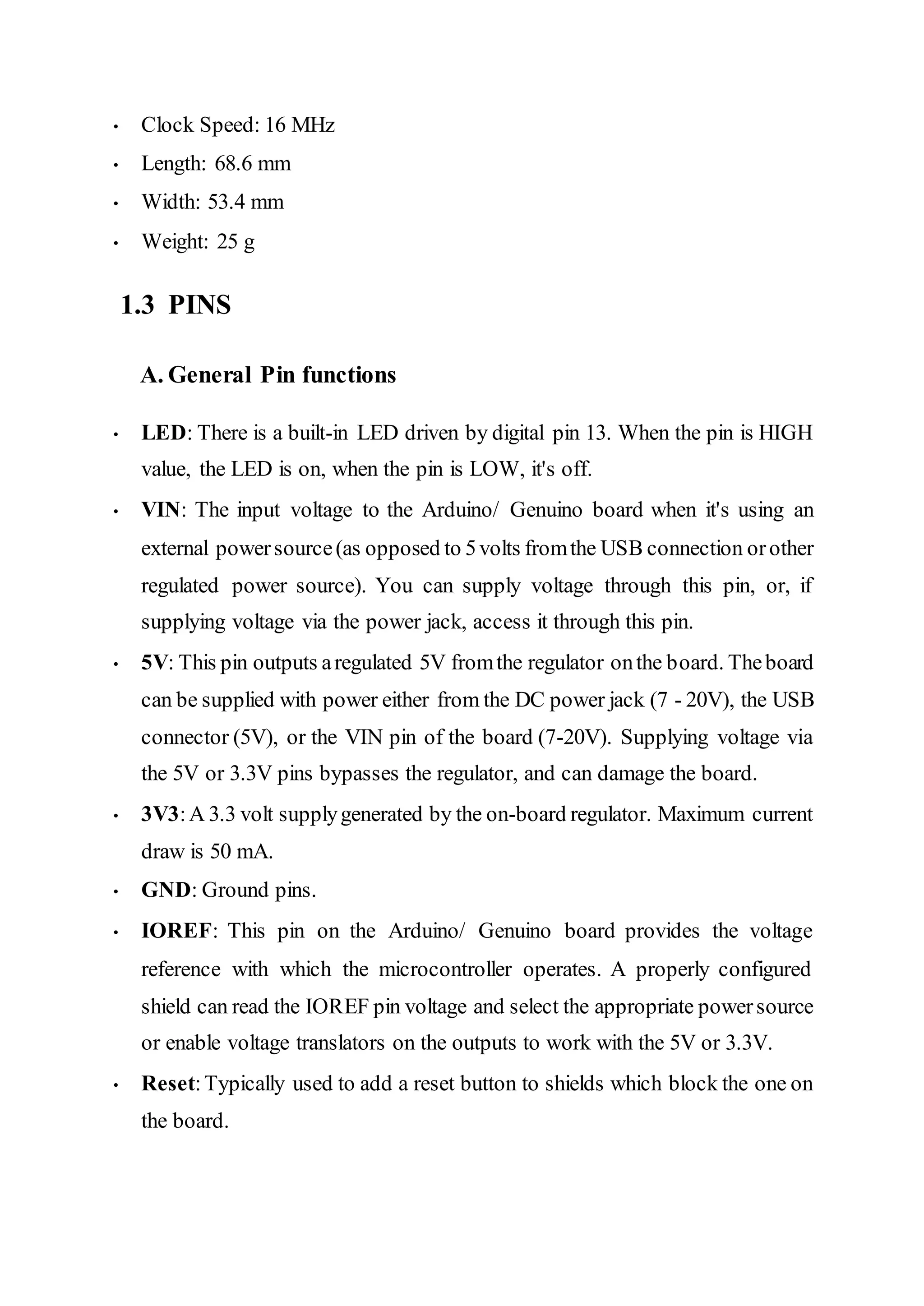
• Clock Speed:16 MHz • Length: 68.6 mm • Width: 53.4 mm • Weight: 25 g 1.3 PINS A. General Pin functions • LED: There is a built-in LED driven by digital pin 13. When the pin is HIGH value, the LED is on, when the pin is LOW, it's off. • VIN: The input voltage to the Arduino/ Genuino board when it's using an external powersource(as opposed to 5volts fromthe USB connection orother regulated power source). You can supply voltage through this pin, or, if supplying voltage via the power jack, access it through this pin. • 5V: This pin outputs aregulated 5V fromthe regulator onthe board. Theboard can be supplied with power either from the DC power jack (7 - 20V), the USB connector (5V), or the VIN pin of the board (7-20V). Supplying voltage via the 5V or 3.3V pins bypasses the regulator, and can damage the board. • 3V3:A 3.3 volt supplygenerated by the on-board regulator. Maximum current draw is 50 mA. • GND: Ground pins. • IOREF: This pin on the Arduino/ Genuino board provides the voltage reference with which the microcontroller operates. A properly configured shield can read the IOREF pin voltage and select the appropriate powersource or enable voltage translators on the outputs to work with the 5V or 3.3V. • Reset:Typically used to add a reset button to shields which block the one on the board.
14.
B. Special PinFunctions Each of the 14 digital pins and 6 Analog pins on the Uno can be used as an input or output, using pinMode (), digitalWrite (), and digitalRead () functions. They operate at 5 volts. Each pin can provide or receive 20 mA as recommended operating condition and has an internal pull-up resistor (disconnected by default) of 20-50k ohm. A maximum of 40mA is the value that must not be exceeded on any I/O pin to avoid permanent damage to the microcontroller. The Uno has 6 analog inputs, labeled A0 through A5, each ofwhich provide 10 bits ofresolution (i.e. 1024 different values). By default they measure from ground to 5 volts, though is it possible to change the upper end of their range using the AREF pin and the analogReference () function. In addition, some pins have specialized functions: • Serial:pins 0 (RX) and 1 (TX). Used to receive (RX) and transmit (TX) TTL serial data. These pins are connected to the corresponding pins of the ATmega8U2 USB-to TTL Serial chip. • External Interrupts: pins 2 and 3. These pins can be configured to trigger an interrupt on a low value, a rising or falling edge, or a change in value. • PWM (Pulse Width Modulation) 3, 5, 6, 9, 10, and 11 Can provide 8-bit PWM output with the analogWrite () function. • SPI(Serial Peripheral Interface): 10 (SS), 11 (MOSI), 12 (MISO), 13 (SCK). These pins support SPI communication using the SPI library. • TWI (Two Wire Interface): A4 orSDA pin and A5 or SCLpin. SupportTWI communication using the Wire library. • AREF (Analog Reference: Reference voltage for the analog inputs. 1.4. Communication
15.
The Arduino/Genuino Unohas a number of facilities for communicating with a computer, another Arduino/Genuino board, or other microcontrollers. The ATmega328 provides UART TTL(5V) serial communication, which is available on digital pins 0 (RX) and 1 (TX). An ATmega16U2 on the board channels this serial communication over USB and appears as a virtual comport to software on the computer. The 16U2 firmware uses the standard USB COM drivers, and no external driver is needed. However, on Windows, a. in file is required. The Arduino Software (IDE) includes a serial monitor which allows simple textual data to be sent to and from the board. The RX and TX LEDs on the board will flash when data is being transmitted via the USB-to-serial chip and USB connection to the computer (but not for serial communication on pins 0 and 1). A Software Serial library allows serial communication on any ofthe Uno's digital pins. 1.5. Automatic (Software) Reset Rather than requiring a physical press of the reset button before an upload, the Arduino/Genuino Uno board is designed in a way that allows it to be reset by software running on a connected computer. One of the hardware flow control lines (DTR) of the ATmega8U2/16U2 is connected to the reset line of the ATmega328 via a 100 Nano farad capacitor. When this line is asserted (taken low), the reset line drops long enough to reset the chip.[7] This setup has other implications. When the Uno is connected to either a computer running Mac OS X or Linux, it resets each time a connection is made to it from software (via USB). Forthe following half-second or so, the bootloader is running on the Uno. While it is programmed to ignore malformed data (i.e. anything besides an upload of new code), it will intercept the first few bytes of data sent to the board after a connection is opened.
16.
2 Atmel ATmega328P The Atmel 8-bit AVR RISC-based microcontroller combines 32 kB ISP flash memory with read-while-write capabilities, 1 kB EEPROM, 2 kB SRAM, 23 general purpose I/O lines, 32 general purpose working registers, three flexible timer/counters with compare modes, internal and external interrupts, serial programmable USART, a byte-oriented 2-wire serial interface, SPI serial port, 6- channel 10-bit A/D converter (8-channels in TQFP and QFN/MLF packages), programmable watchdog timer with internal oscillator, and five software selectable power saving modes. The device operates between 1.8-5.5 volts. The device achieves throughput approaching 1 MIPS per MHz Table 1. Parameter Value CPU type 8-bit AVR Performance 20 MIPS at 20 MHz[2] Flash memory 32 kB SRAM 2 kB EEPROM 1 kB Pin count 28-pin PDIP, MLF, 32-pin TQFP, MLF[2]
17.
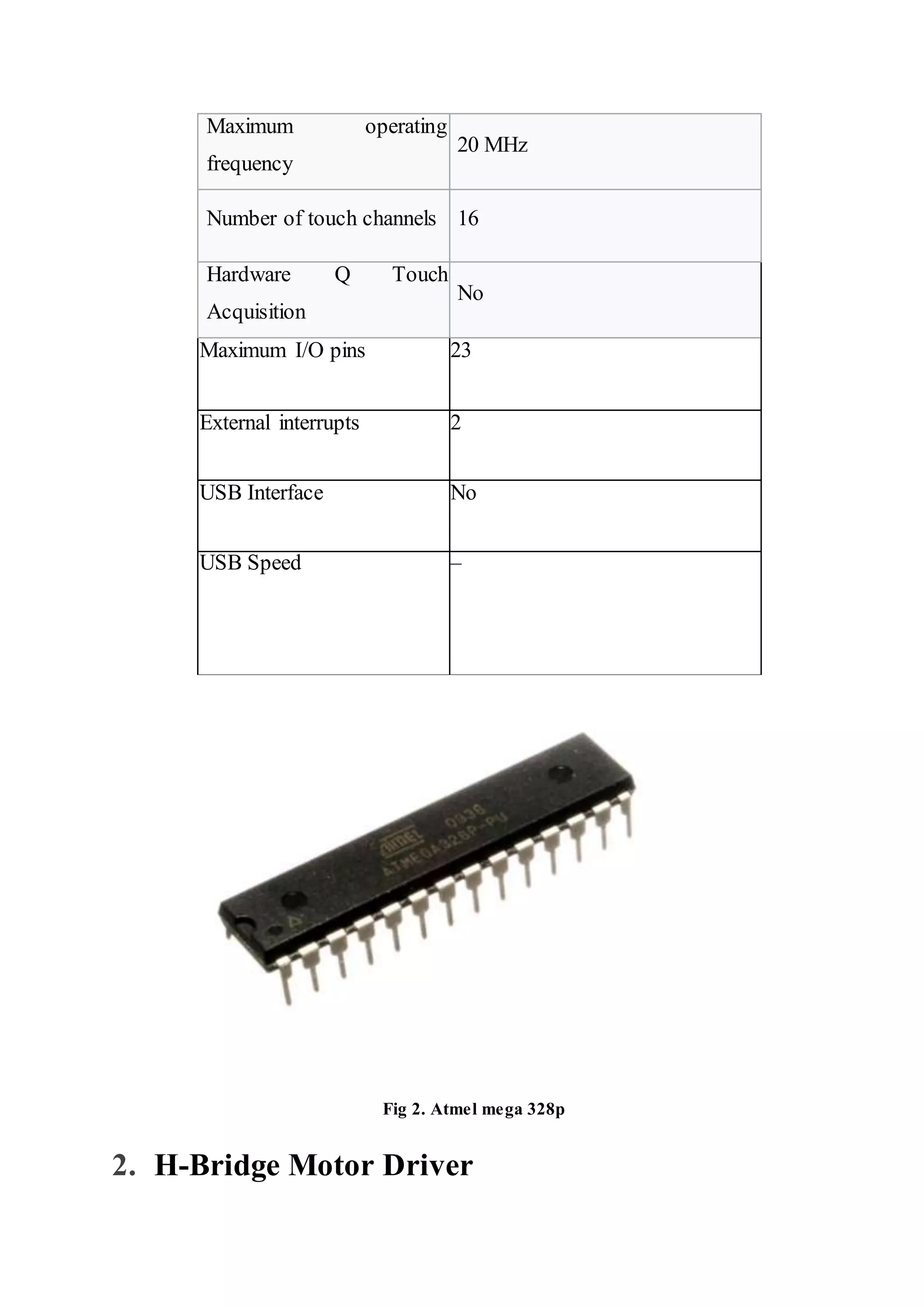
Maximum operating frequency 20 MHz Numberof touch channels 16 Hardware Q Touch Acquisition No Maximum I/O pins 23 External interrupts 2 USB Interface No USB Speed – Fig 2. Atmel mega 328p 2. H-Bridge Motor Driver
18.
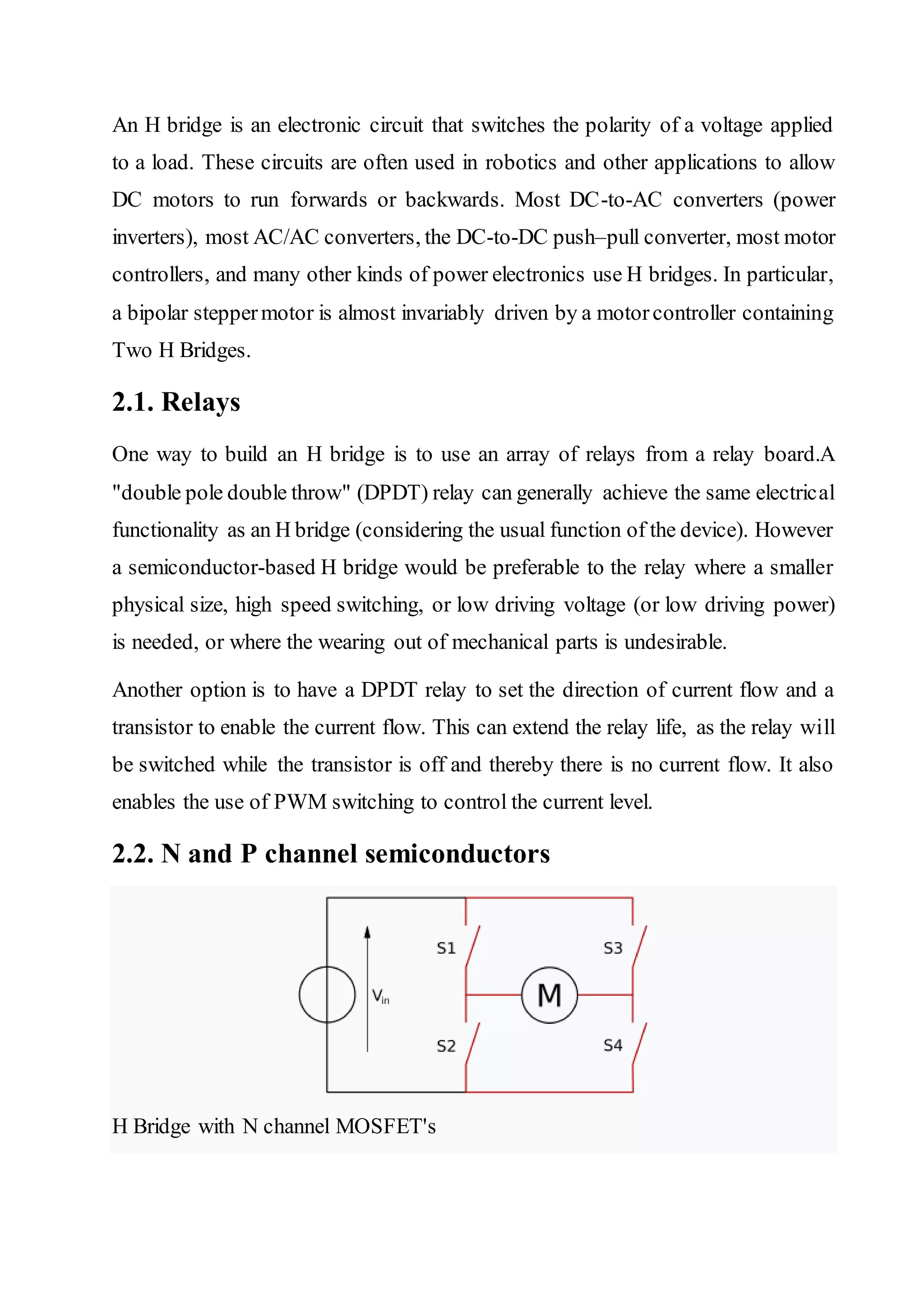
An H bridgeis an electronic circuit that switches the polarity of a voltage applied to a load. These circuits are often used in robotics and other applications to allow DC motors to run forwards or backwards. Most DC-to-AC converters (power inverters), most AC/AC converters, the DC-to-DC push–pull converter, most motor controllers, and many other kinds of power electronics use H bridges. In particular, a bipolar steppermotor is almost invariably driven by a motorcontroller containing Two H Bridges. 2.1. Relays One way to build an H bridge is to use an array of relays from a relay board.A "double pole double throw" (DPDT) relay can generally achieve the same electrical functionality as an H bridge (considering the usual function of the device). However a semiconductor-based H bridge would be preferable to the relay where a smaller physical size, high speed switching, or low driving voltage (or low driving power) is needed, or where the wearing out of mechanical parts is undesirable. Another option is to have a DPDT relay to set the direction of current flow and a transistor to enable the current flow. This can extend the relay life, as the relay will be switched while the transistor is off and thereby there is no current flow. It also enables the use of PWM switching to control the current level. 2.2. N and P channel semiconductors H Bridge with N channel MOSFET's
19.
A solid-state Hbridge is typically constructed using oppositepolarity devices, such as PNP bipolar junction transistors (BJT) or P-channel MOSFETs connected to the high voltage bus and NPN BJTs or N-channel MOSFETs connected to the low voltage bus. 2.3. N channel-only semiconductors The most efficient MOSFET designs use N-channel MOSFETs on both the high side and low side because they typically have a third of the ON resistance of P- channel MOSFETs. This requires a more complex design since the gates ofthe high side MOSFETs must be driven positive with respect to the DC supply rail. Many integrated circuit MOSFET gate drivers include a charge pump within the device to achieve this. Alternatively, a switched-mode power supply DC–DC converter can be used to provide isolated ('floating') supplies to the gate drive circuitry. A multiple-output fly back converter is well-suited to this application. Another method for driving MOSFET-bridges is the use of a specialized transformer known as a GDT (gate drive transformer), which gives the isolated outputs for driving the upper FETs gates. The transformer core is usually a ferrite toroid, with 1:1 or 4:9 winding ratio. However, this method can only be used with high frequency signals. The design of the transformer is also very important, as the leakage inductance should be minimized, or cross conduction may occur. The outputs of the transformer are usually clamped by Zener diodes, because high voltage spikes could destroy the MOSFET gates. 2.4. Variants A common variation of this circuit uses just the two transistors on one side of the load, similar to a class AB amplifier. Such a configuration is called a "half bridge".[3] The half bridge is used in some switched-mode power supplies that
20.
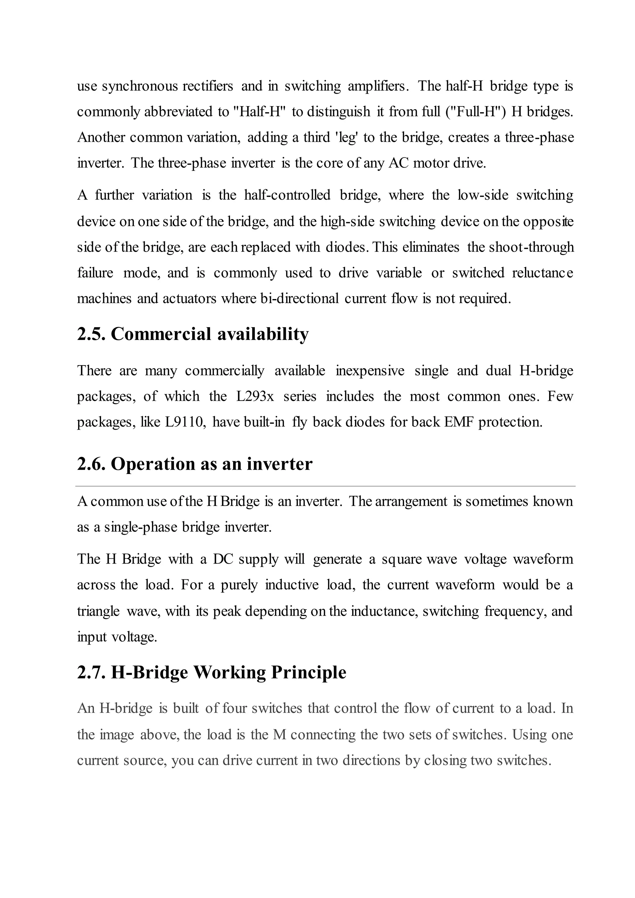
use synchronous rectifiersand in switching amplifiers. The half-H bridge type is commonly abbreviated to "Half-H" to distinguish it from full ("Full-H") H bridges. Another common variation, adding a third 'leg' to the bridge, creates a three-phase inverter. The three-phase inverter is the core of any AC motor drive. A further variation is the half-controlled bridge, where the low-side switching device on one side of the bridge, and the high-side switching device on the opposite side of the bridge, are each replaced with diodes. This eliminates the shoot-through failure mode, and is commonly used to drive variable or switched reluctance machines and actuators where bi-directional current flow is not required. 2.5. Commercial availability There are many commercially available inexpensive single and dual H-bridge packages, of which the L293x series includes the most common ones. Few packages, like L9110, have built-in fly back diodes for back EMF protection. 2.6. Operation as an inverter A common use ofthe H Bridge is an inverter. The arrangement is sometimes known as a single-phase bridge inverter. The H Bridge with a DC supply will generate a square wave voltage waveform across the load. For a purely inductive load, the current waveform would be a triangle wave, with its peak depending on the inductance, switching frequency, and input voltage. 2.7. H-Bridge Working Principle An H-bridge is built of four switches that control the flow of current to a load. In the image above, the load is the M connecting the two sets of switches. Using one current source, you can drive current in two directions by closing two switches.
21.
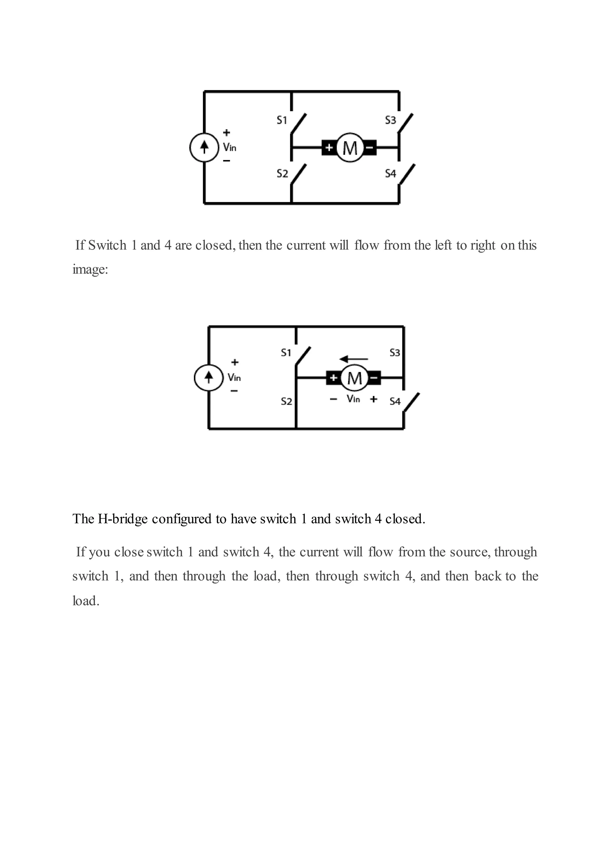
If Switch 1and 4 are closed, then the current will flow from the left to right on this image: The H-bridge configured to have switch 1 and switch 4 closed. If you close switch 1 and switch 4, the current will flow from the source, through switch 1, and then through the load, then through switch 4, and then back to the load.
22.
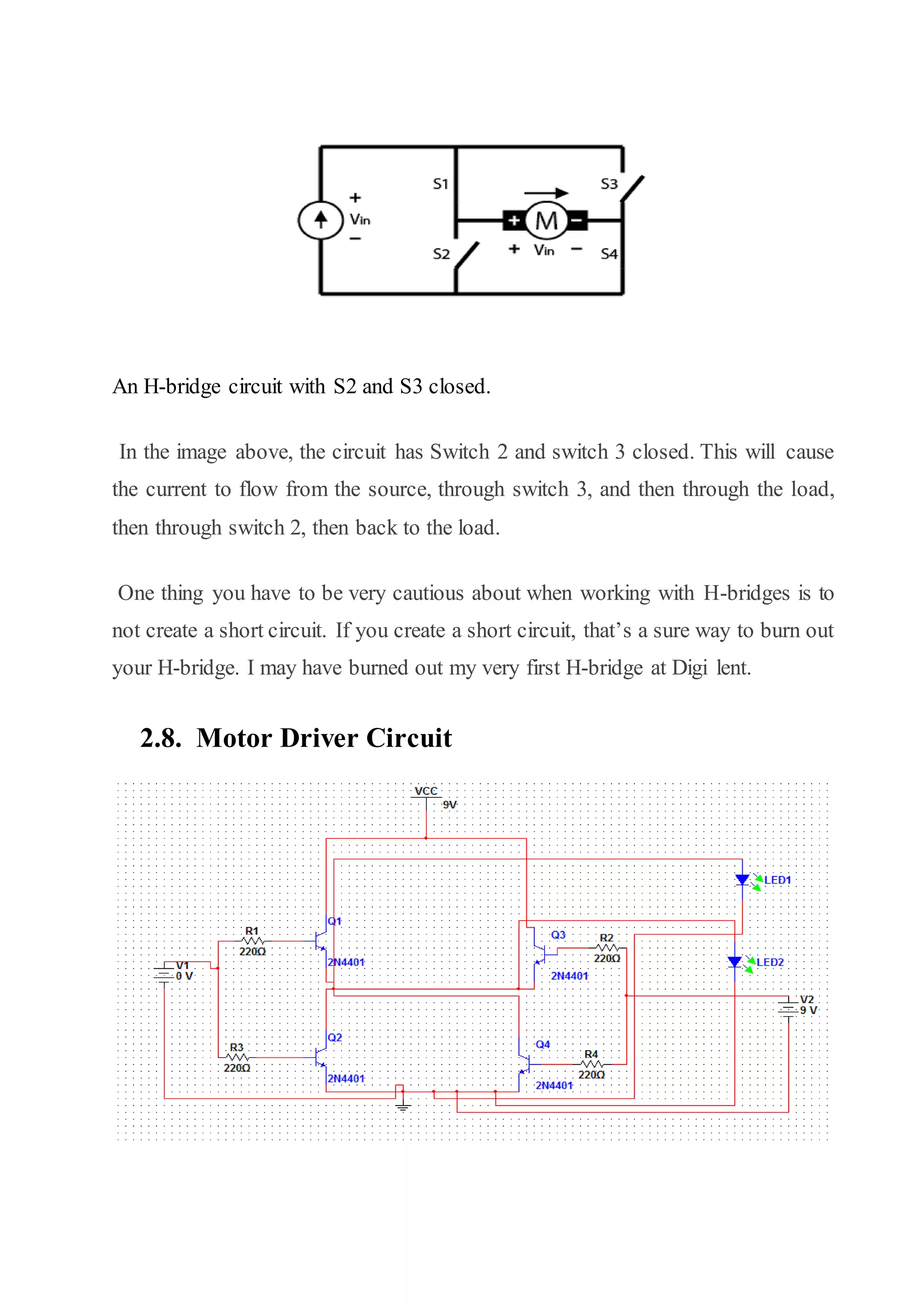
An H-bridge circuitwith S2 and S3 closed. In the image above, the circuit has Switch 2 and switch 3 closed. This will cause the current to flow from the source, through switch 3, and then through the load, then through switch 2, then back to the load. One thing you have to be very cautious about when working with H-bridges is to not create a short circuit. If you create a short circuit, that’s a sure way to burn out your H-bridge. I may have burned out my very first H-bridge at Digi lent. 2.8. Motor Driver Circuit
23.
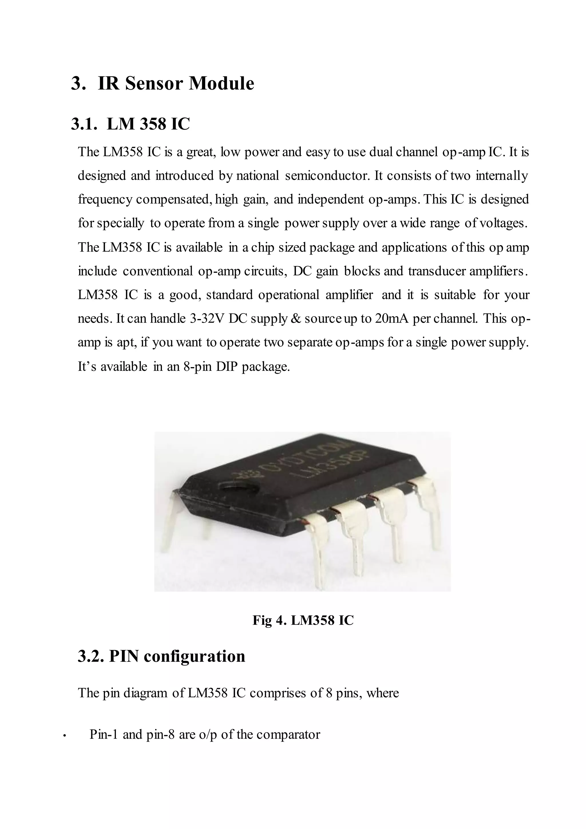
3. IR SensorModule 3.1. LM 358 IC The LM358 IC is a great, low power and easy to use dual channel op-amp IC. It is designed and introduced by national semiconductor. It consists of two internally frequency compensated, high gain, and independent op-amps. This IC is designed for specially to operate from a single power supply over a wide range of voltages. The LM358 IC is available in a chip sized package and applications of this op amp include conventional op-amp circuits, DC gain blocks and transducer amplifiers. LM358 IC is a good, standard operational amplifier and it is suitable for your needs. It can handle 3-32V DC supply & sourceup to 20mA per channel. This op- amp is apt, if you want to operate two separate op-amps for a single power supply. It’s available in an 8-pin DIP package. Fig 4. LM358 IC 3.2. PIN configuration The pin diagram of LM358 IC comprises of 8 pins, where • Pin-1 and pin-8 are o/p of the comparator
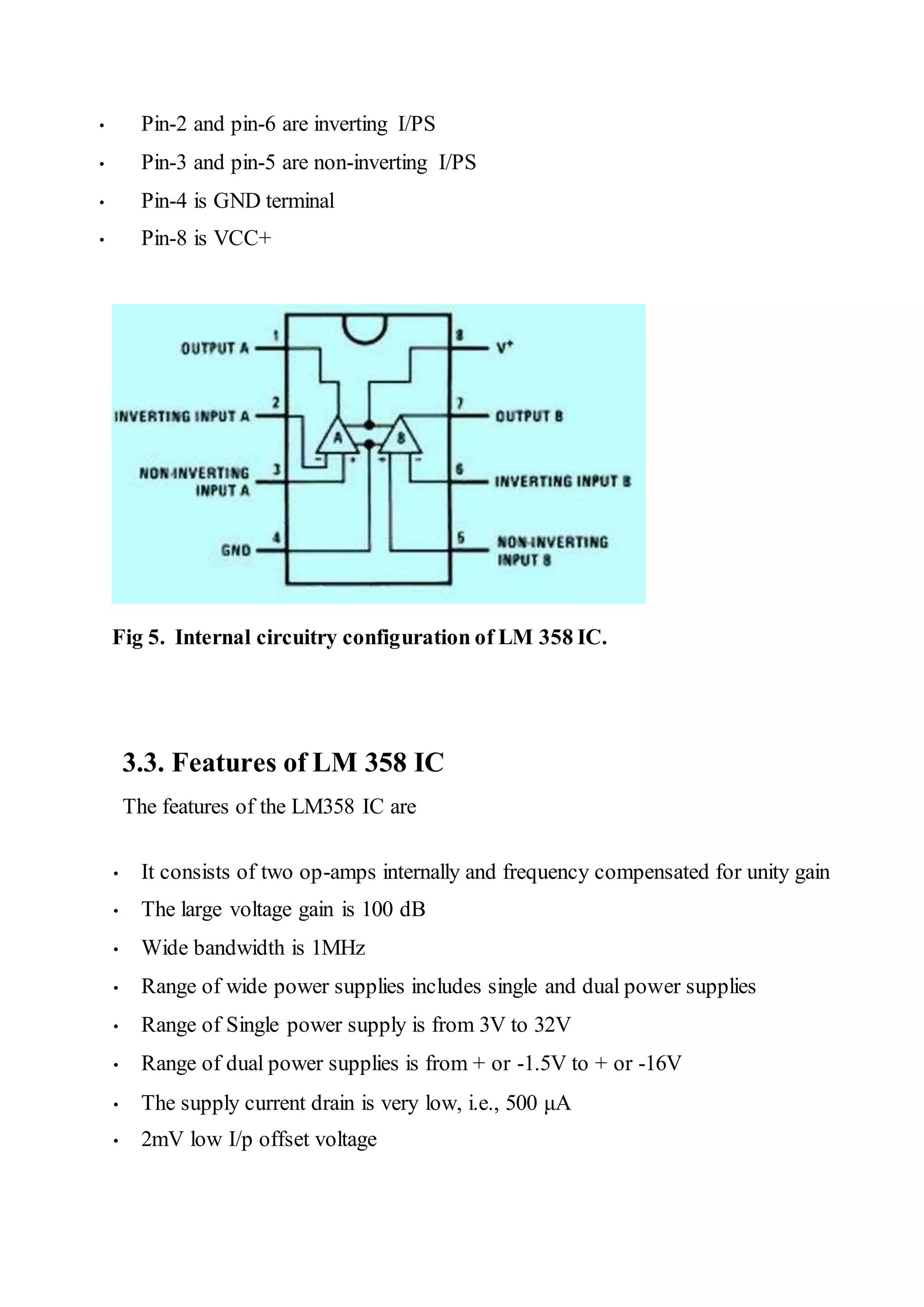
24.
• Pin-2 andpin-6 are inverting I/PS • Pin-3 and pin-5 are non-inverting I/PS • Pin-4 is GND terminal • Pin-8 is VCC+ Fig 5. Internal circuitry configuration of LM 358 IC. 3.3. Features of LM 358 IC The features of the LM358 IC are • It consists of two op-amps internally and frequency compensated for unity gain • The large voltage gain is 100 dB • Wide bandwidth is 1MHz • Range of wide power supplies includes single and dual power supplies • Range of Single power supply is from 3V to 32V • Range of dual power supplies is from + or -1.5V to + or -16V • The supply current drain is very low, i.e., 500 μA • 2mV low I/p offset voltage
25.
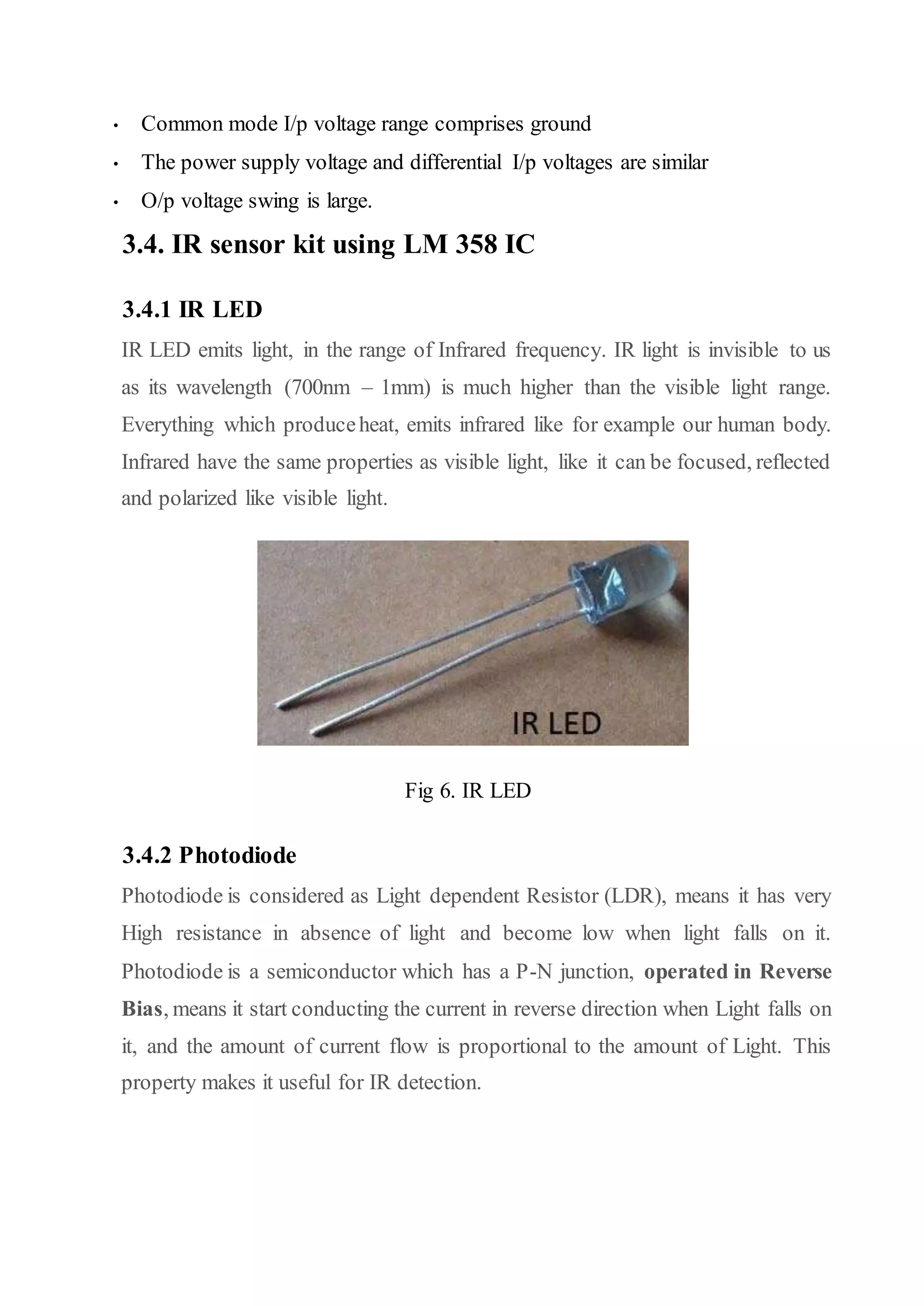
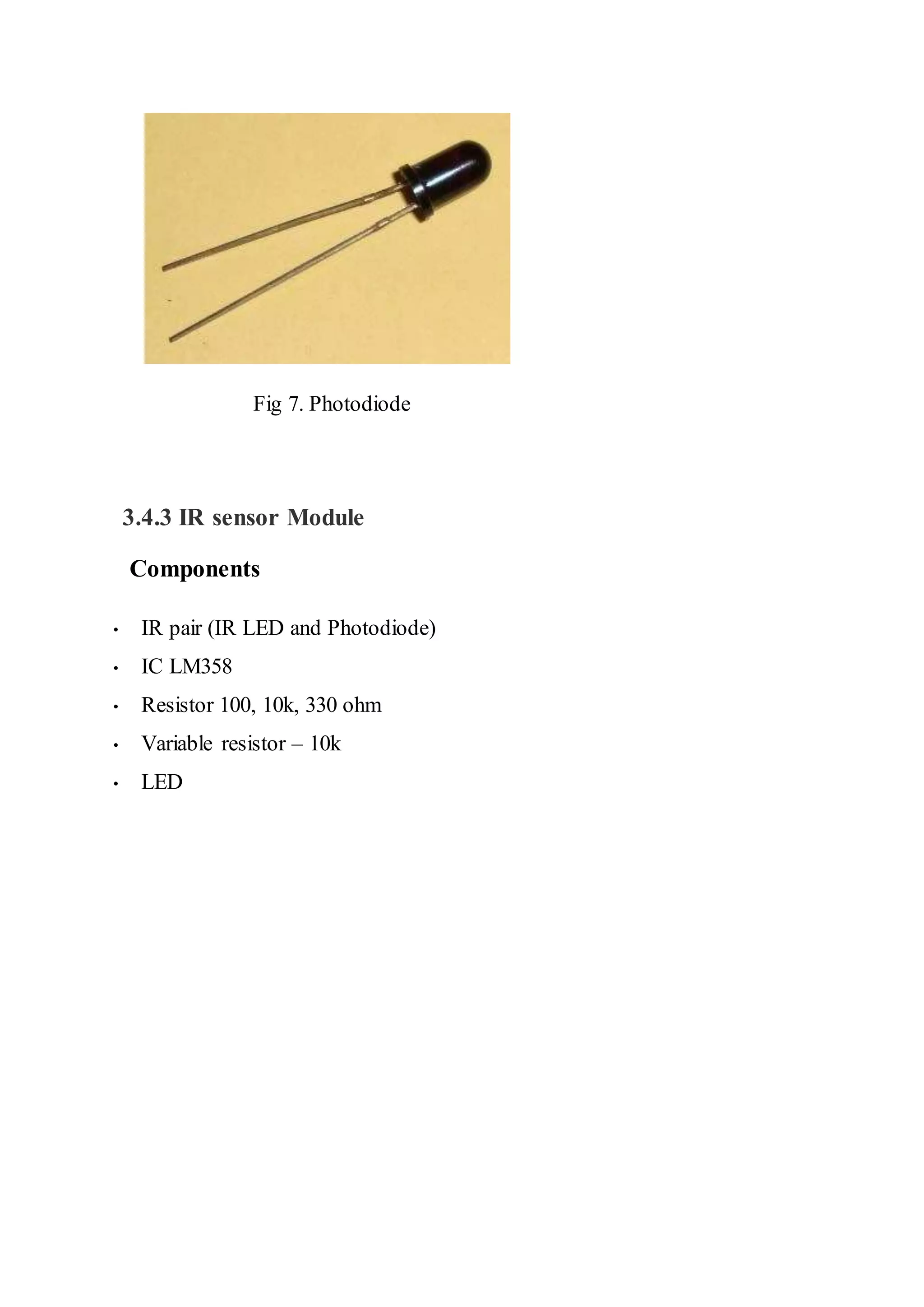
• Common modeI/p voltage range comprises ground • The power supply voltage and differential I/p voltages are similar • O/p voltage swing is large. 3.4. IR sensor kit using LM 358 IC 3.4.1 IR LED IR LED emits light, in the range of Infrared frequency. IR light is invisible to us as its wavelength (700nm – 1mm) is much higher than the visible light range. Everything which produceheat, emits infrared like for example our human body. Infrared have the same properties as visible light, like it can be focused, reflected and polarized like visible light. Fig 6. IR LED 3.4.2 Photodiode Photodiode is considered as Light dependent Resistor (LDR), means it has very High resistance in absence of light and become low when light falls on it. Photodiode is a semiconductor which has a P-N junction, operated in Reverse Bias, means it start conducting the current in reverse direction when Light falls on it, and the amount of current flow is proportional to the amount of Light. This property makes it useful for IR detection.
26.
Fig 7. Photodiode 3.4.3IR sensor Module Components • IR pair (IR LED and Photodiode) • IC LM358 • Resistor 100, 10k, 330 ohm • Variable resistor – 10k • LED
27.
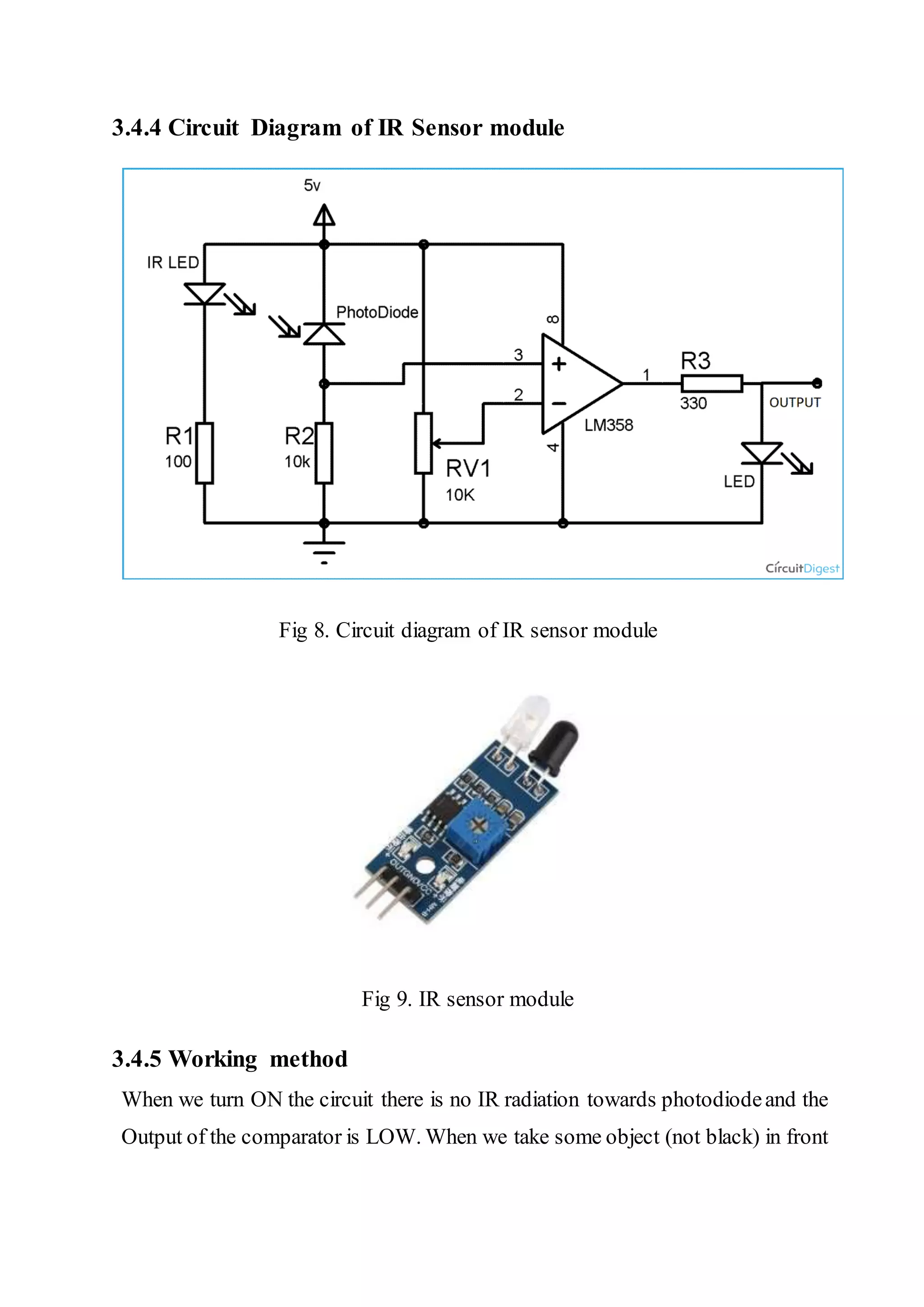
3.4.4 Circuit Diagramof IR Sensor module Fig 8. Circuit diagram of IR sensor module Fig 9. IR sensor module 3.4.5 Working method When we turn ON the circuit there is no IR radiation towards photodiodeand the Output of the comparator is LOW. When we take some object (not black) in front
28.
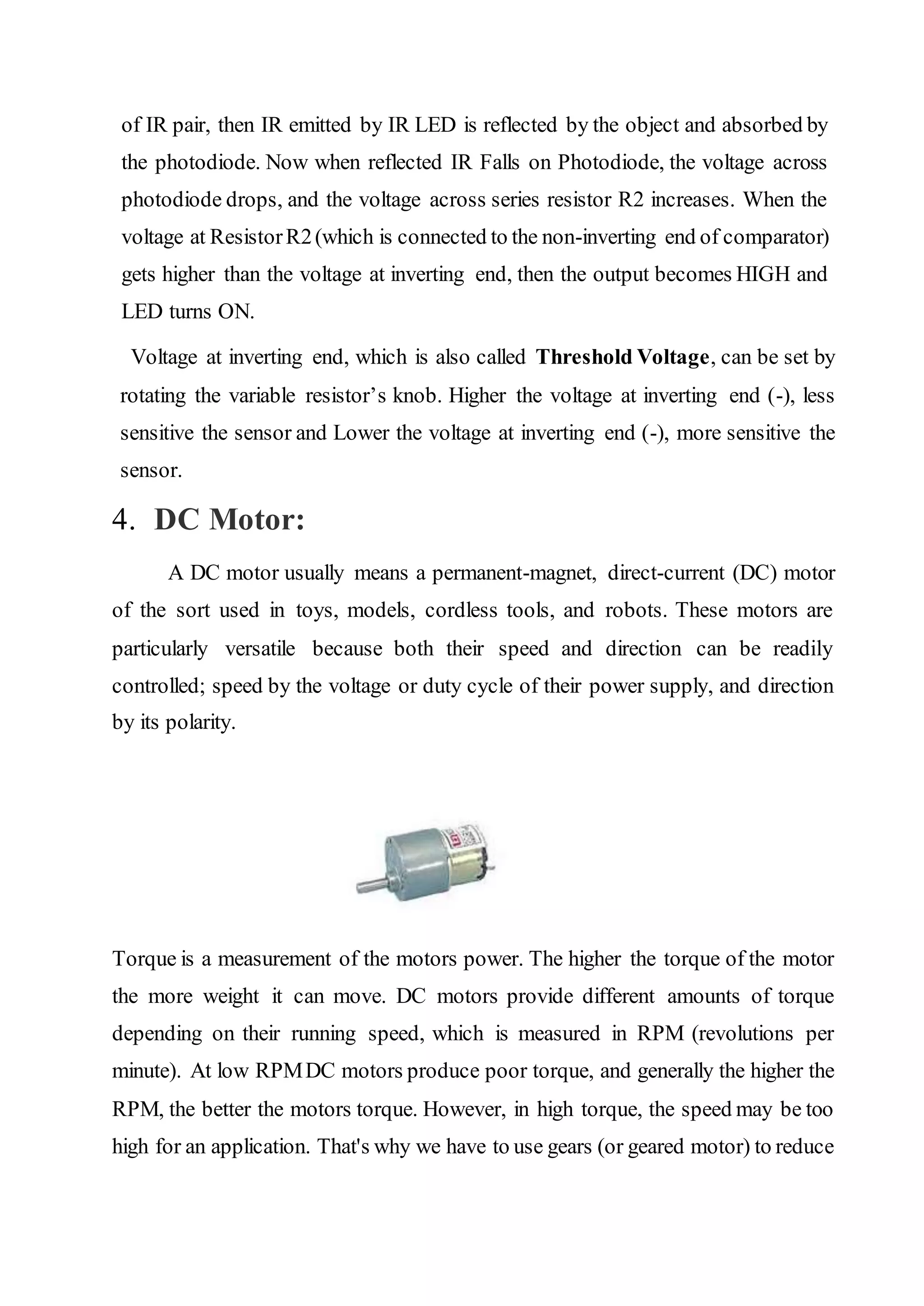
of IR pair,then IR emitted by IR LED is reflected by the object and absorbed by the photodiode. Now when reflected IR Falls on Photodiode, the voltage across photodiode drops, and the voltage across series resistor R2 increases. When the voltage at ResistorR2(which is connected to the non-inverting end of comparator) gets higher than the voltage at inverting end, then the output becomes HIGH and LED turns ON. Voltage at inverting end, which is also called Threshold Voltage, can be set by rotating the variable resistor’s knob. Higher the voltage at inverting end (-), less sensitive the sensor and Lower the voltage at inverting end (-), more sensitive the sensor. 4. DC Motor: A DC motor usually means a permanent-magnet, direct-current (DC) motor of the sort used in toys, models, cordless tools, and robots. These motors are particularly versatile because both their speed and direction can be readily controlled; speed by the voltage or duty cycle of their power supply, and direction by its polarity. Torque is a measurement of the motors power. The higher the torque of the motor the more weight it can move. DC motors provide different amounts of torque depending on their running speed, which is measured in RPM (revolutions per minute). At low RPMDC motors produce poor torque, and generally the higher the RPM, the better the motors torque. However, in high torque, the speed may be too high for an application. That's why we have to use gears (or geared motor) to reduce
29.
the overall speedof the motor and running at the top speed to get the most power to, say, a wheel attached to the shaft of the motor. 5. Battery A 9V battery is required to supply the dc power to drive the Arduino Uno and other components connected to the Arduino. 6. Software Arduino IDE is used to develop the prototype of the software. Arduino IDE is available at the official website of Arduino. This is open source. So any one can develop anything according to their choices.
30.
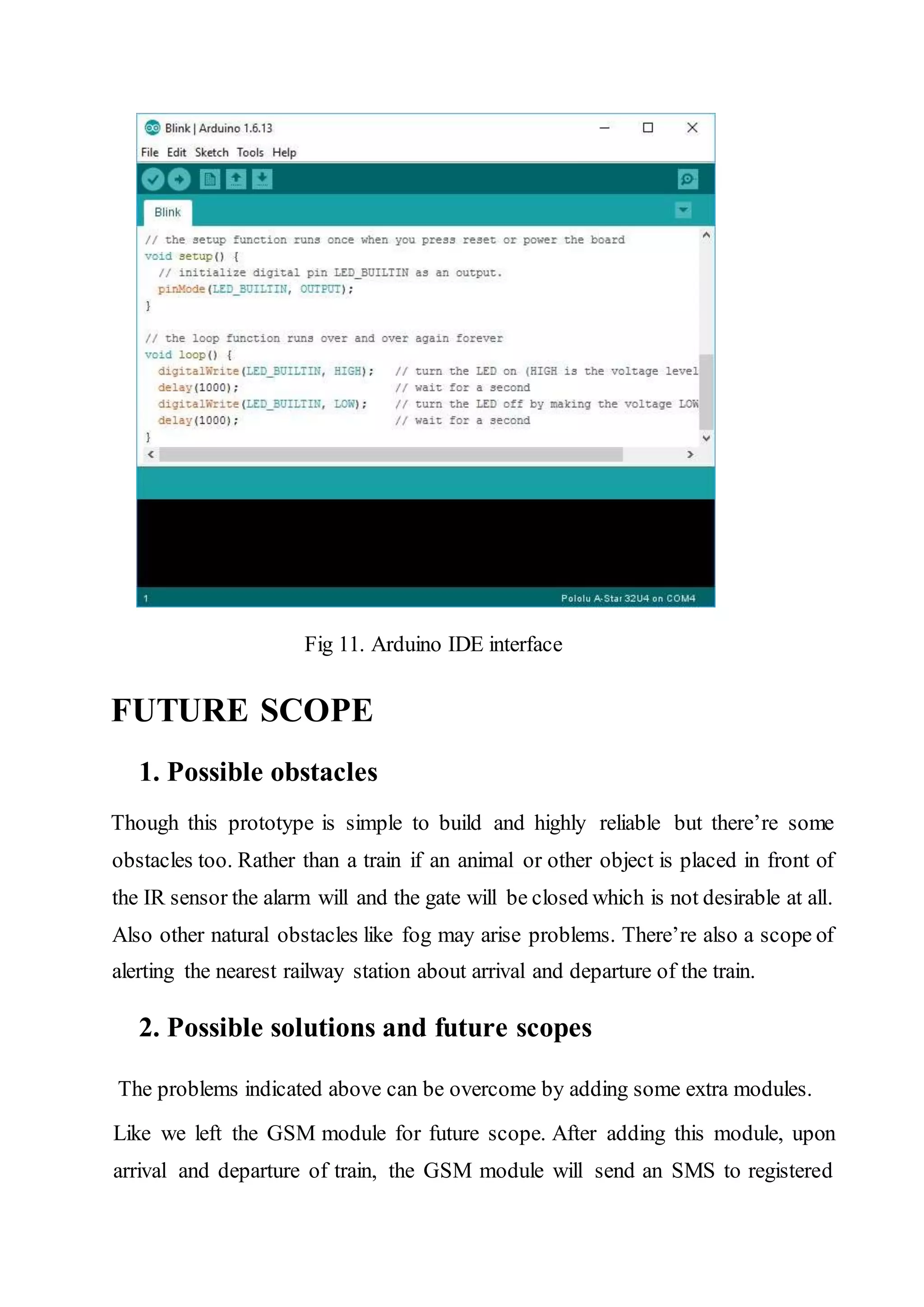
Fig 11. ArduinoIDE interface FUTURE SCOPE 1. Possible obstacles Though this prototype is simple to build and highly reliable but there’re some obstacles too. Rather than a train if an animal or other object is placed in front of the IR sensor the alarm will and the gate will be closed which is not desirable at all. Also other natural obstacles like fog may arise problems. There’re also a scope of alerting the nearest railway station about arrival and departure of the train. 2. Possible solutions and future scopes The problems indicated above can be overcome by adding some extra modules. Like we left the GSM module for future scope. After adding this module, upon arrival and departure of train, the GSM module will send an SMS to registered
31.
phone number foracknowledgement and safety. Also adding a pair of pressure sensorincreases the chance of fault triggering of gate as well as alarm. After adding the pressure sensor, the Arduino closes the gate after receiving both signal from IR sensor as well as pressure sensor. Problems: Working in this project, some problems have been faced by us .The problems are given below: First ofall, the value of resistances should be changed as the voltage changes with the change of light .It is very difficult to vary the resistance for the perfect operation. Another problem is IR sensor easily damages so that the operation hampers. IR sensoris light dependent sensor. It varies with the change of light so it is not applicable for all environment. IR sensor works at a certain distance .If the distance is increased the IR will not work which is a drawback of this project. Discussion: This project helps us to know about the operations of IR sensor and Arduino Uno. Though the project has some limitations for using in practical purpose, its concept is very useful to us. This project can be improved by using LASER and LDR for increasing the distance for real train .A buzzer can be added for safety .This project can be developed in future using the conceptwhich will be preferable for practical use. CONCLUSION
32.
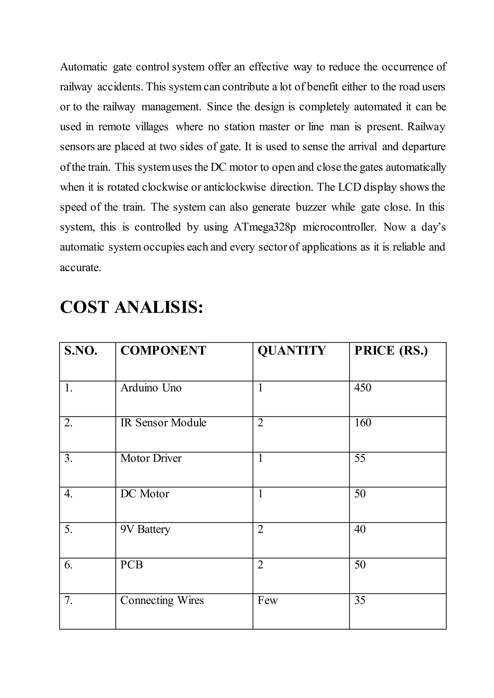
Automatic gate controlsystem offer an effective way to reduce the occurrence of railway accidents. This system can contribute a lot of benefit either to the road users or to the railway management. Since the design is completely automated it can be used in remote villages where no station master or line man is present. Railway sensors are placed at two sides of gate. It is used to sense the arrival and departure ofthe train. This systemuses the DC motor to open and close the gates automatically when it is rotated clockwise or anticlockwise direction. The LCD display shows the speed of the train. The system can also generate buzzer while gate close. In this system, this is controlled by using ATmega328p microcontroller. Now a day’s automatic system occupies each and every sectorof applications as it is reliable and accurate. COST ANALISIS: S.NO. COMPONENT QUANTITY PRICE (RS.) 1. Arduino Uno 1 450 2. IR Sensor Module 2 160 3. Motor Driver 1 55 4. DC Motor 1 50 5. 9V Battery 2 40 6. PCB 2 50 7. Connecting Wires Few 35
33.
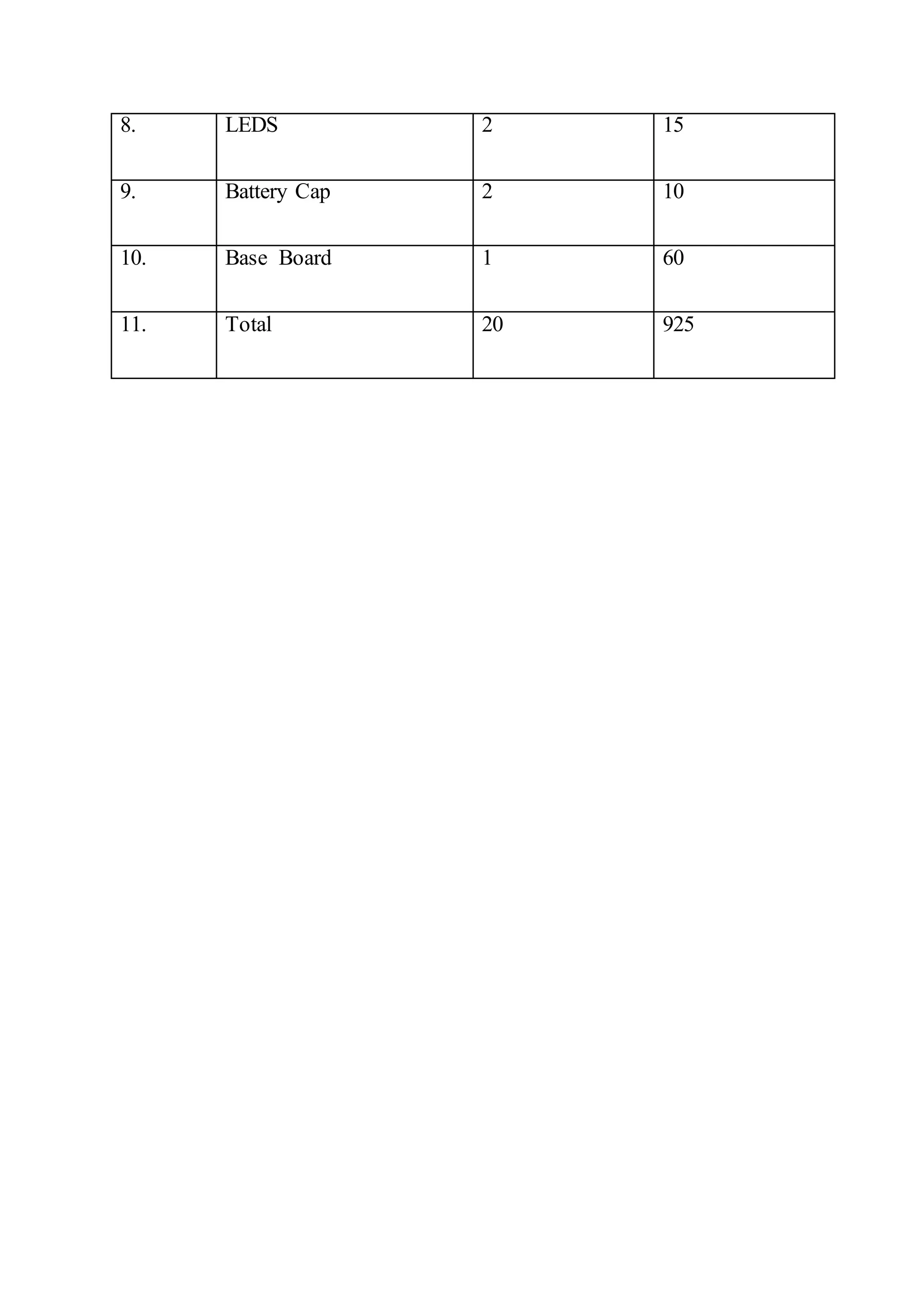
8. LEDS 215 9. Battery Cap 2 10 10. Base Board 1 60 11. Total 20 925


![5. DC Motor 6. Buzzer 7. LEDs 8. Jumper Wires Description of components 1. Arduino Uno 1.1. Arduino Uno R3 The Arduino UNO is a widely used open-sourcemicrocontroller board based on the ATmega328P microcontroller and developed by Arduino.cc. The board is equipped with sets of digital and analog input/output (I/O) pins that may be interfaced to various expansion boards (shields) and other circuits.[1] The board features 14 Digital pins and 6 Analog pins. It is programmable with the Arduino IDE (Integrated Development](https://image.slidesharecdn.com/automaticrailwaygatecontrolusingarduinouno11-200115161150/75/Automatic-railway-gate-control-using-arduino-uno-11-2048.jpg)
![Environment) via a type B USB cable. It can be powered by a USB cable or by an external 9 volt battery, though it accepts voltages between 7 and 20 volts. It is also similar to the Arduino Nano and Leonardo. The hardware reference design is distributed under a Creative Commons Attribution Share-Alike 2.5 license and is available on the Arduino website. Layout and production files for some versions of the hardware are also available. "Uno" means one in Italian and was chosento mark the release of Arduino Software (IDE) 1.0.The Uno board and version 1.0 of Arduino Software (IDE) were the reference versions of Arduino, now evolved to newer releases. The Uno board is the first in a series of USB Arduino boards, and the reference model for the Arduino platform.[3] The ATmega328 on the Arduino Uno comes preprogrammed with a bootloaderthat allows to upload new code to it without the use of an external hardware programmer. It communicates using the original STK500 protocol. The Uno also differs from all preceding boards in that it does not use the FTDI USB-to-serial driver chip. Instead, it features the Atmega16U2 (Atmega8U2 up to version R2) programmed as a USB- to-serial converter. 1.2 Technical Specifications • Microcontroller: ATmega328P • Operating Voltage: 5v • Input Voltage: 7-20v • Digital I/O Pins: 14 (of which 6 provide PWM output) • Analog Input Pins: 6 • DC Current per I/O Pin: 20 mA • DC Current for 3.3V Pin: 50 mA • Flash Memory: 32 KB of which 0.5 KB used by bootloader • SRAM: 2 KB • EEPROM: 1 KB](https://image.slidesharecdn.com/automaticrailwaygatecontrolusingarduinouno11-200115161150/75/Automatic-railway-gate-control-using-arduino-uno-12-2048.jpg)

![The Arduino/Genuino Uno has a number of facilities for communicating with a computer, another Arduino/Genuino board, or other microcontrollers. The ATmega328 provides UART TTL(5V) serial communication, which is available on digital pins 0 (RX) and 1 (TX). An ATmega16U2 on the board channels this serial communication over USB and appears as a virtual comport to software on the computer. The 16U2 firmware uses the standard USB COM drivers, and no external driver is needed. However, on Windows, a. in file is required. The Arduino Software (IDE) includes a serial monitor which allows simple textual data to be sent to and from the board. The RX and TX LEDs on the board will flash when data is being transmitted via the USB-to-serial chip and USB connection to the computer (but not for serial communication on pins 0 and 1). A Software Serial library allows serial communication on any ofthe Uno's digital pins. 1.5. Automatic (Software) Reset Rather than requiring a physical press of the reset button before an upload, the Arduino/Genuino Uno board is designed in a way that allows it to be reset by software running on a connected computer. One of the hardware flow control lines (DTR) of the ATmega8U2/16U2 is connected to the reset line of the ATmega328 via a 100 Nano farad capacitor. When this line is asserted (taken low), the reset line drops long enough to reset the chip.[7] This setup has other implications. When the Uno is connected to either a computer running Mac OS X or Linux, it resets each time a connection is made to it from software (via USB). Forthe following half-second or so, the bootloader is running on the Uno. While it is programmed to ignore malformed data (i.e. anything besides an upload of new code), it will intercept the first few bytes of data sent to the board after a connection is opened.](https://image.slidesharecdn.com/automaticrailwaygatecontrolusingarduinouno11-200115161150/75/Automatic-railway-gate-control-using-arduino-uno-15-2048.jpg)
![2 Atmel ATmega 328P The Atmel 8-bit AVR RISC-based microcontroller combines 32 kB ISP flash memory with read-while-write capabilities, 1 kB EEPROM, 2 kB SRAM, 23 general purpose I/O lines, 32 general purpose working registers, three flexible timer/counters with compare modes, internal and external interrupts, serial programmable USART, a byte-oriented 2-wire serial interface, SPI serial port, 6- channel 10-bit A/D converter (8-channels in TQFP and QFN/MLF packages), programmable watchdog timer with internal oscillator, and five software selectable power saving modes. The device operates between 1.8-5.5 volts. The device achieves throughput approaching 1 MIPS per MHz Table 1. Parameter Value CPU type 8-bit AVR Performance 20 MIPS at 20 MHz[2] Flash memory 32 kB SRAM 2 kB EEPROM 1 kB Pin count 28-pin PDIP, MLF, 32-pin TQFP, MLF[2]](https://image.slidesharecdn.com/automaticrailwaygatecontrolusingarduinouno11-200115161150/75/Automatic-railway-gate-control-using-arduino-uno-16-2048.jpg)
![A solid-state H bridge is typically constructed using oppositepolarity devices, such as PNP bipolar junction transistors (BJT) or P-channel MOSFETs connected to the high voltage bus and NPN BJTs or N-channel MOSFETs connected to the low voltage bus. 2.3. N channel-only semiconductors The most efficient MOSFET designs use N-channel MOSFETs on both the high side and low side because they typically have a third of the ON resistance of P- channel MOSFETs. This requires a more complex design since the gates ofthe high side MOSFETs must be driven positive with respect to the DC supply rail. Many integrated circuit MOSFET gate drivers include a charge pump within the device to achieve this. Alternatively, a switched-mode power supply DC–DC converter can be used to provide isolated ('floating') supplies to the gate drive circuitry. A multiple-output fly back converter is well-suited to this application. Another method for driving MOSFET-bridges is the use of a specialized transformer known as a GDT (gate drive transformer), which gives the isolated outputs for driving the upper FETs gates. The transformer core is usually a ferrite toroid, with 1:1 or 4:9 winding ratio. However, this method can only be used with high frequency signals. The design of the transformer is also very important, as the leakage inductance should be minimized, or cross conduction may occur. The outputs of the transformer are usually clamped by Zener diodes, because high voltage spikes could destroy the MOSFET gates. 2.4. Variants A common variation of this circuit uses just the two transistors on one side of the load, similar to a class AB amplifier. Such a configuration is called a "half bridge".[3] The half bridge is used in some switched-mode power supplies that](https://image.slidesharecdn.com/automaticrailwaygatecontrolusingarduinouno11-200115161150/75/Automatic-railway-gate-control-using-arduino-uno-19-2048.jpg)