Objectives • To learnthe architectures of ARM processor, principal features • To understand the registers and processor modes • To study about the register set in ARM
3.
Introduction • ARM processorshave dominated the microcontroller market • ARM is used in various real life applications for control and automation • ARM has developed various versions for variety of applications
4.
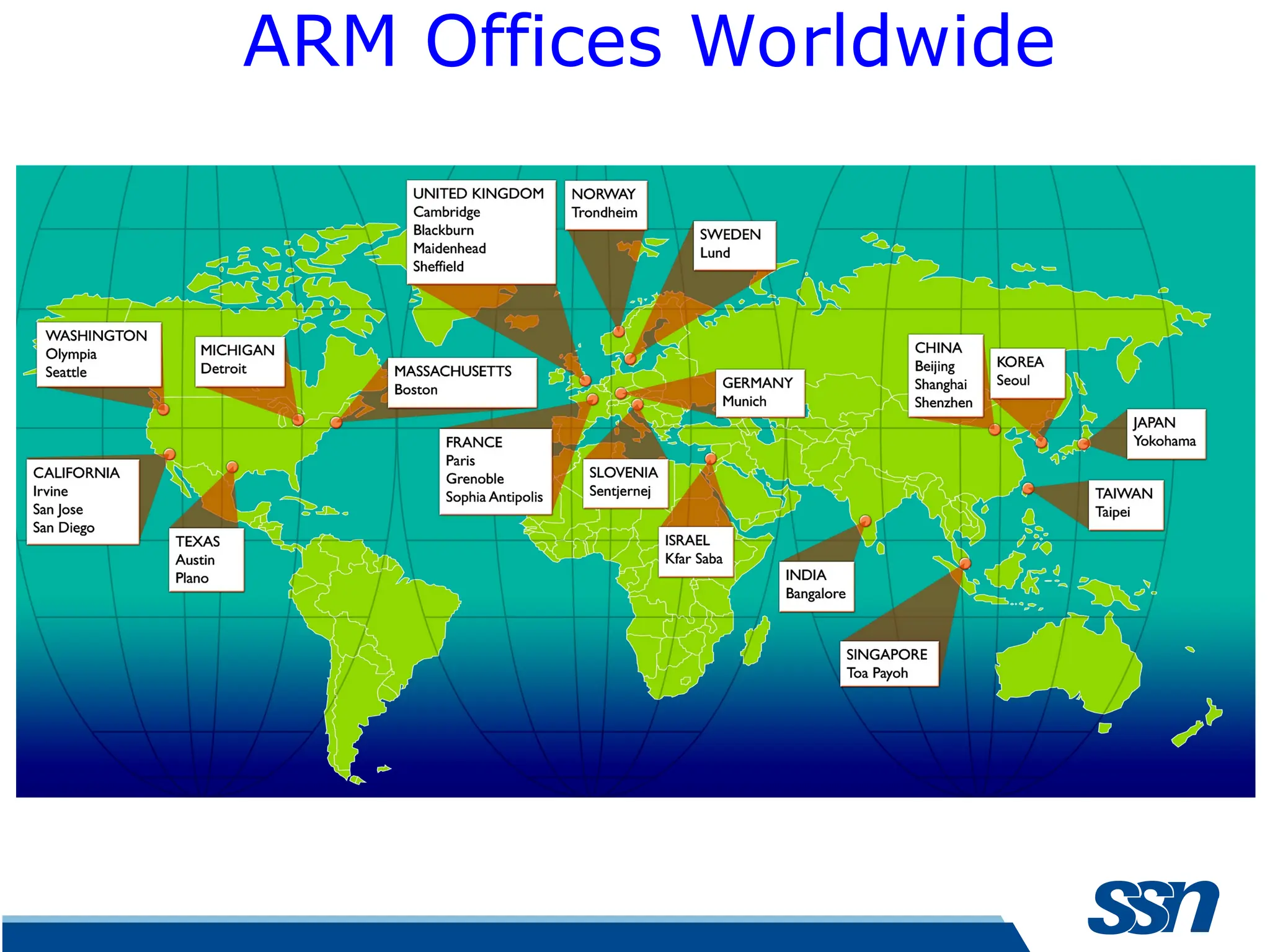
ARM Ltd ARMfounded in November 1990 Advanced RISC Machines Company headquarters in Cambridge, UK Processor design centers in Cambridge, Austin, and Sophia Antipolis Sales, support, and engineering offices all over the world Best known for its range of RISC processor cores designs Other products – fabric IP, software tools, models, cell libraries - to help partners develop and ship ARM-based SoCs ARM does not manufacture silicon http://www.arm.com/aboutarm/
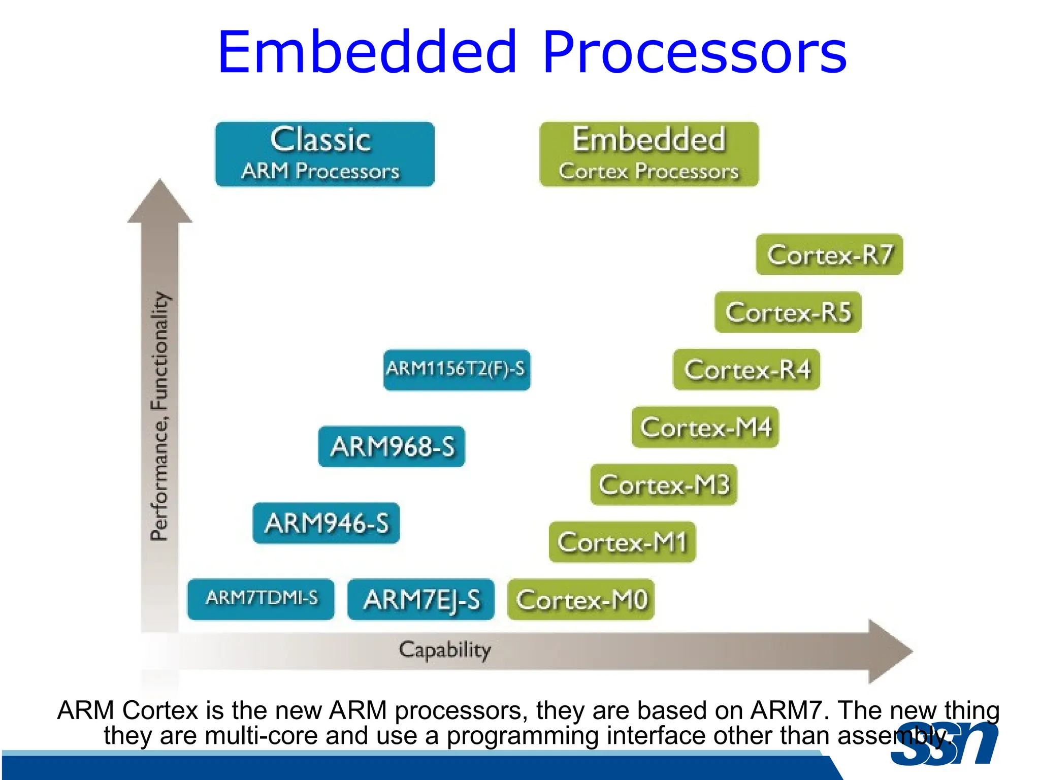
Embedded Processors ARM Cortexis the new ARM processors, they are based on ARM7. The new thing they are multi-core and use a programming interface other than assembly.
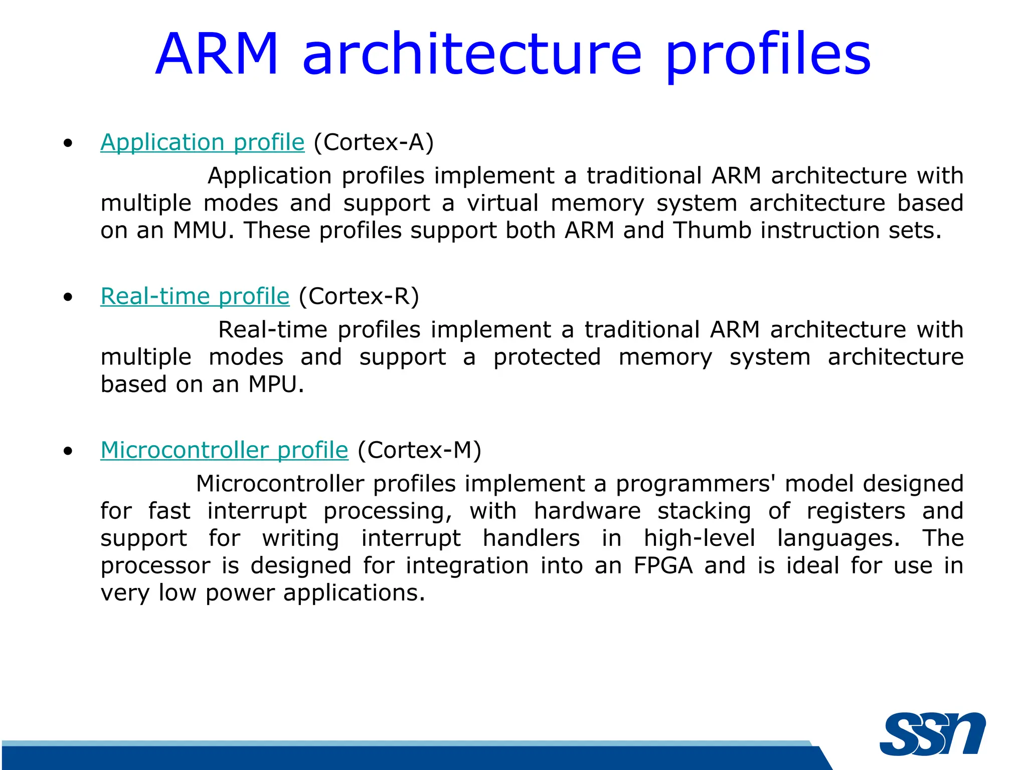
ARM architecture profiles •Application profile (Cortex-A) Application profiles implement a traditional ARM architecture with multiple modes and support a virtual memory system architecture based on an MMU. These profiles support both ARM and Thumb instruction sets. • Real-time profile (Cortex-R) Real-time profiles implement a traditional ARM architecture with multiple modes and support a protected memory system architecture based on an MPU. • Microcontroller profile (Cortex-M) Microcontroller profiles implement a programmers' model designed for fast interrupt processing, with hardware stacking of registers and support for writing interrupt handlers in high-level languages. The processor is designed for integration into an FPGA and is ideal for use in very low power applications.
10.
M series • TheM series ARM CPU's – small instruction set, – often no floating point unit, – no memory management, no cache. – optimized for low cost rather than high performance. – generally combined with FLASH, RAM and peripherals into a micro-controller chip. – mostly used to control hardware, and programmed either bare metal (without libraries) or linked with some libraries that could provide OS-like features. – ARM likes to see these CPUs as 8-bit and 16-bit micro- controller .
11.
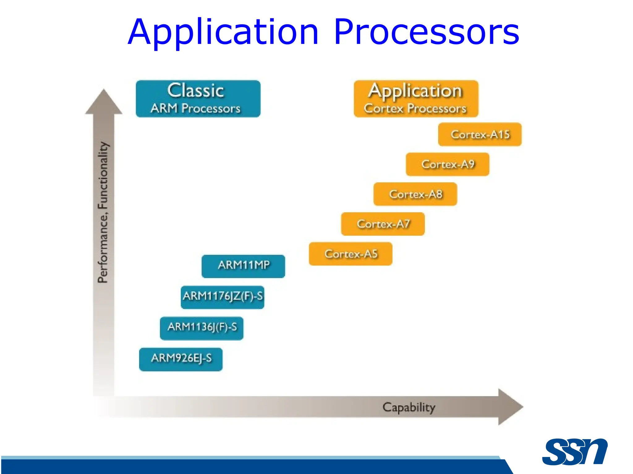
A Series • TheA series ARM CPU's – have a larger instruction set – have a floating point unit, – memory management unit, and cache(s). – optimized for high performance rather than low cost – generally sold as mirco-processor (often combined with high- end peripherals like ethernet, video, mpeg decoder), intended to be combined with off-chip RAM and FLASH. – Often run some OS, often Linux, with a separation between OS space and space for application programs. – ARM likes to see these CPUs as THE choice for mobile phones and tablets (competing with the intel CPUs).
12.
ARM Architecture -Principal features • Large set of registers, all of which can be used for most purposes • Load-store architecture • 3-address instructions(two source operand registers and result register –all independently specified • Conditional execution of every instruction • Powerful load and store multiple register instructions
13.
Principal features • Abilityto perform a general shift operation and a general ALU operation in a single instruction in a single CLK cycle • Open instruction set extension through co- processor instruction set • Very dense 16-bit compressed representation of instruction set in thumb architecture
14.
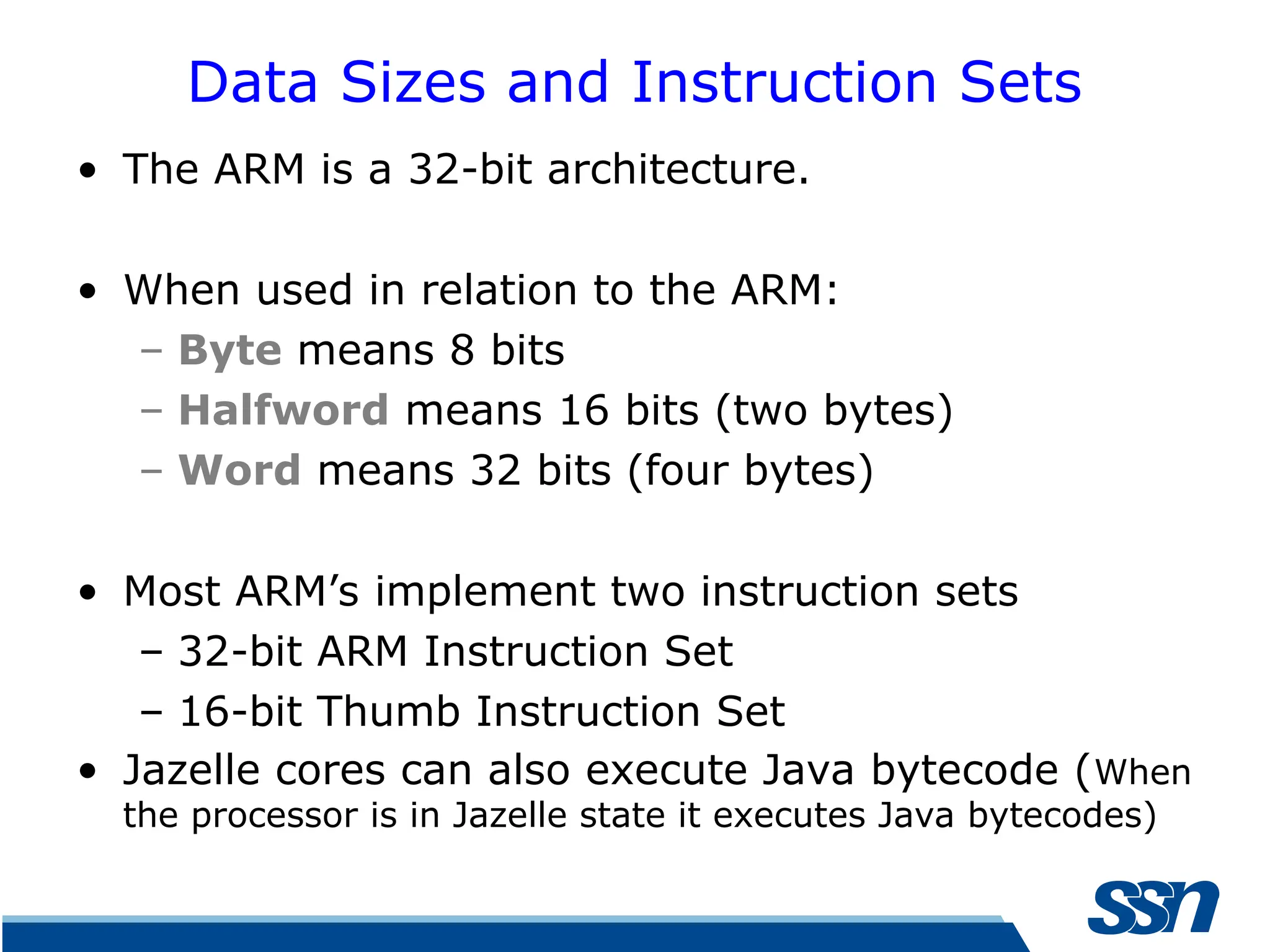
Data Sizes andInstruction Sets • The ARM is a 32-bit architecture. • When used in relation to the ARM: – Byte means 8 bits – Halfword means 16 bits (two bytes) – Word means 32 bits (four bytes) • Most ARM’s implement two instruction sets – 32-bit ARM Instruction Set – 16-bit Thumb Instruction Set • Jazelle cores can also execute Java bytecode (When the processor is in Jazelle state it executes Java bytecodes)
15.
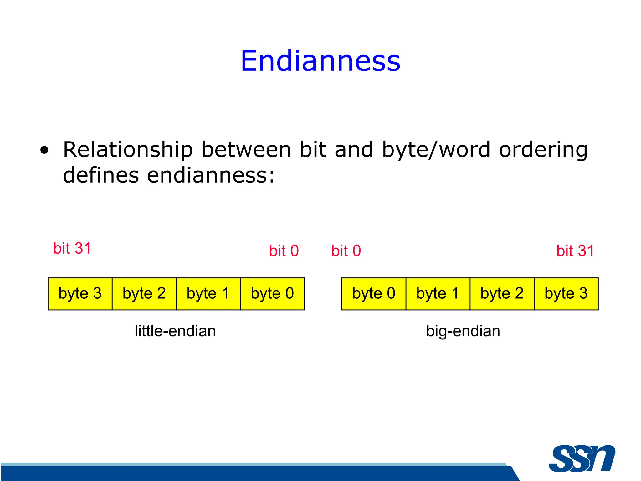
Endianness • Relationship betweenbit and byte/word ordering defines endianness: byte 3 byte 2 byte 1 byte 0 byte 0 byte 1 byte 2 byte 3 bit 31 bit 0 bit 0 bit 31 little-endian big-endian
16.
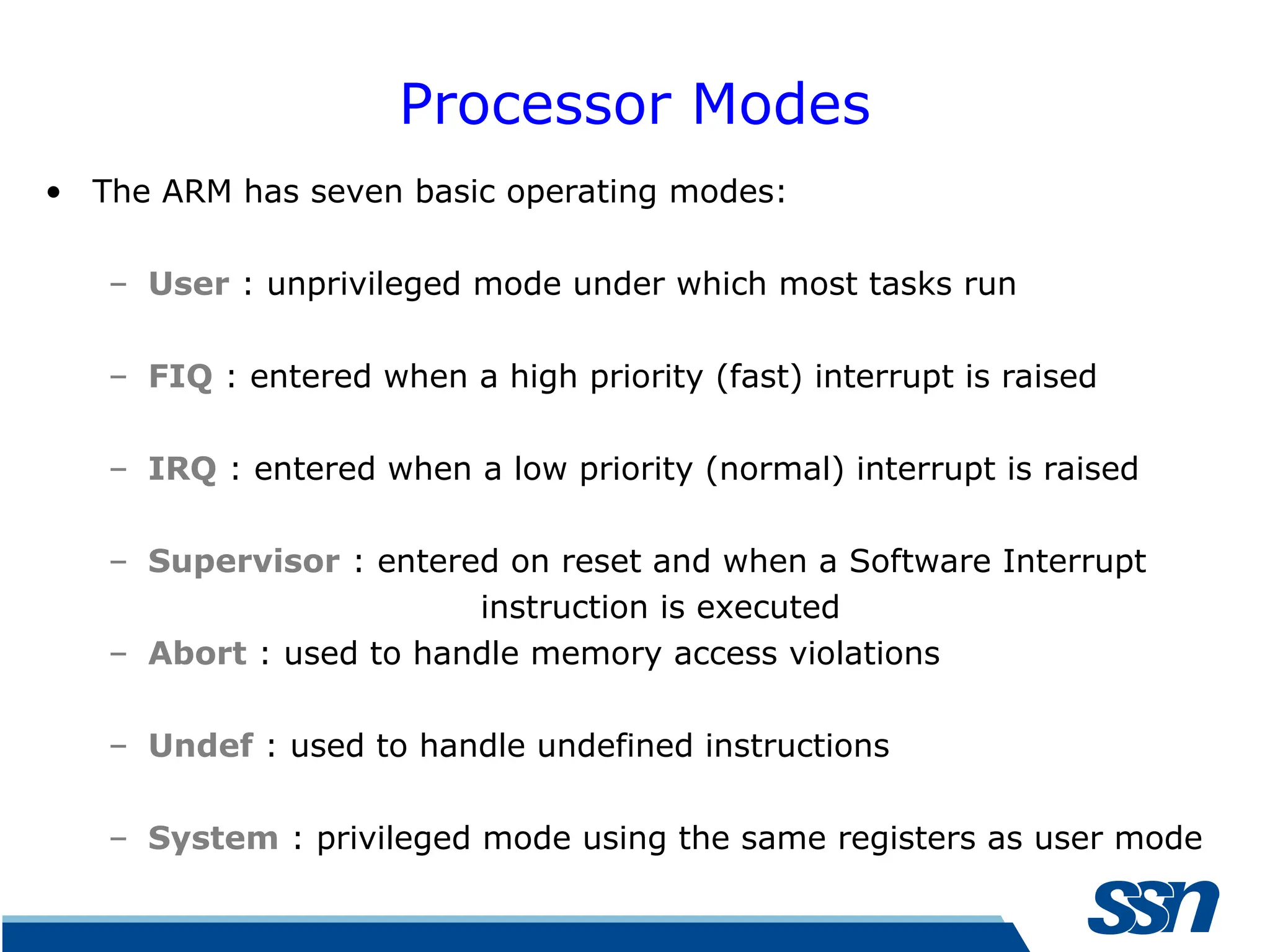
Processor Modes • TheARM has seven basic operating modes: – User : unprivileged mode under which most tasks run – FIQ : entered when a high priority (fast) interrupt is raised – IRQ : entered when a low priority (normal) interrupt is raised – Supervisor : entered on reset and when a Software Interrupt instruction is executed – Abort : used to handle memory access violations – Undef : used to handle undefined instructions – System : privileged mode using the same registers as user mode
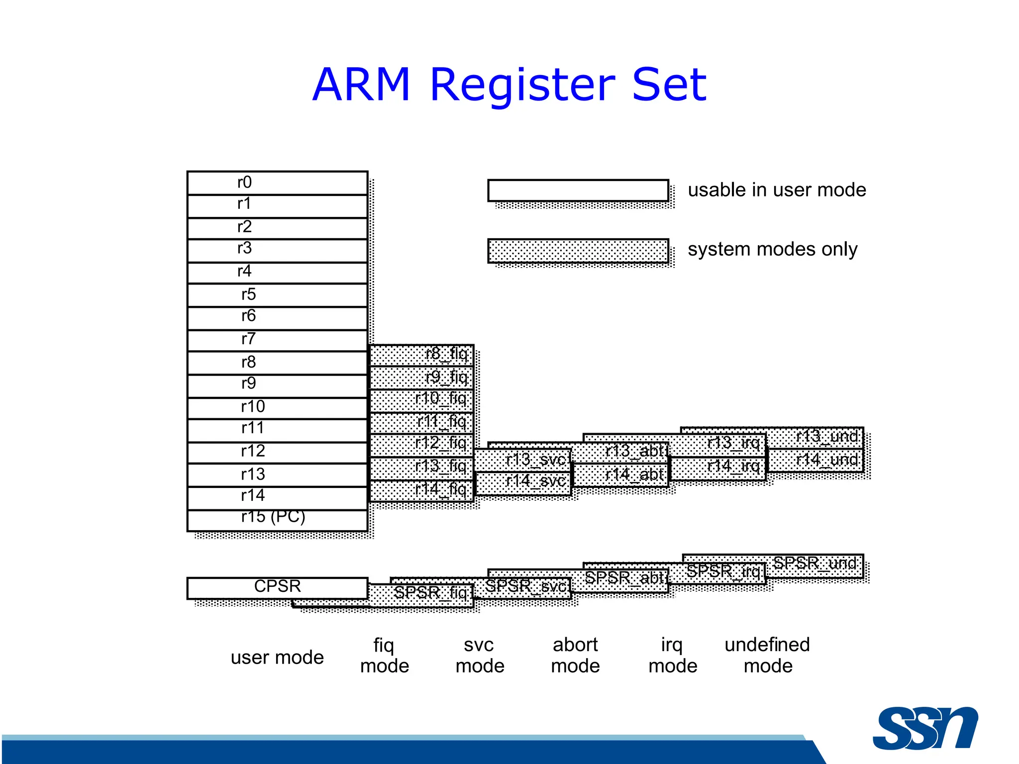
ARM Register Set r13_und r14_und r14_irq r13_irq SPSR_und r14_abt r14_svc usermode fiq mode svc mode abort mode irq mode undefined mode usable in user mode system modes only r13_abt r13_svc r8_fiq r9_fiq r10_fiq r11_fiq SPSR_irq SPSR_abt SPSR_svc SPSR_fiq CPSR r14_fiq r13_fiq r12_fiq r0 r1 r2 r3 r4 r5 r6 r7 r8 r9 r10 r11 r12 r13 r14 r15 (PC)
19.
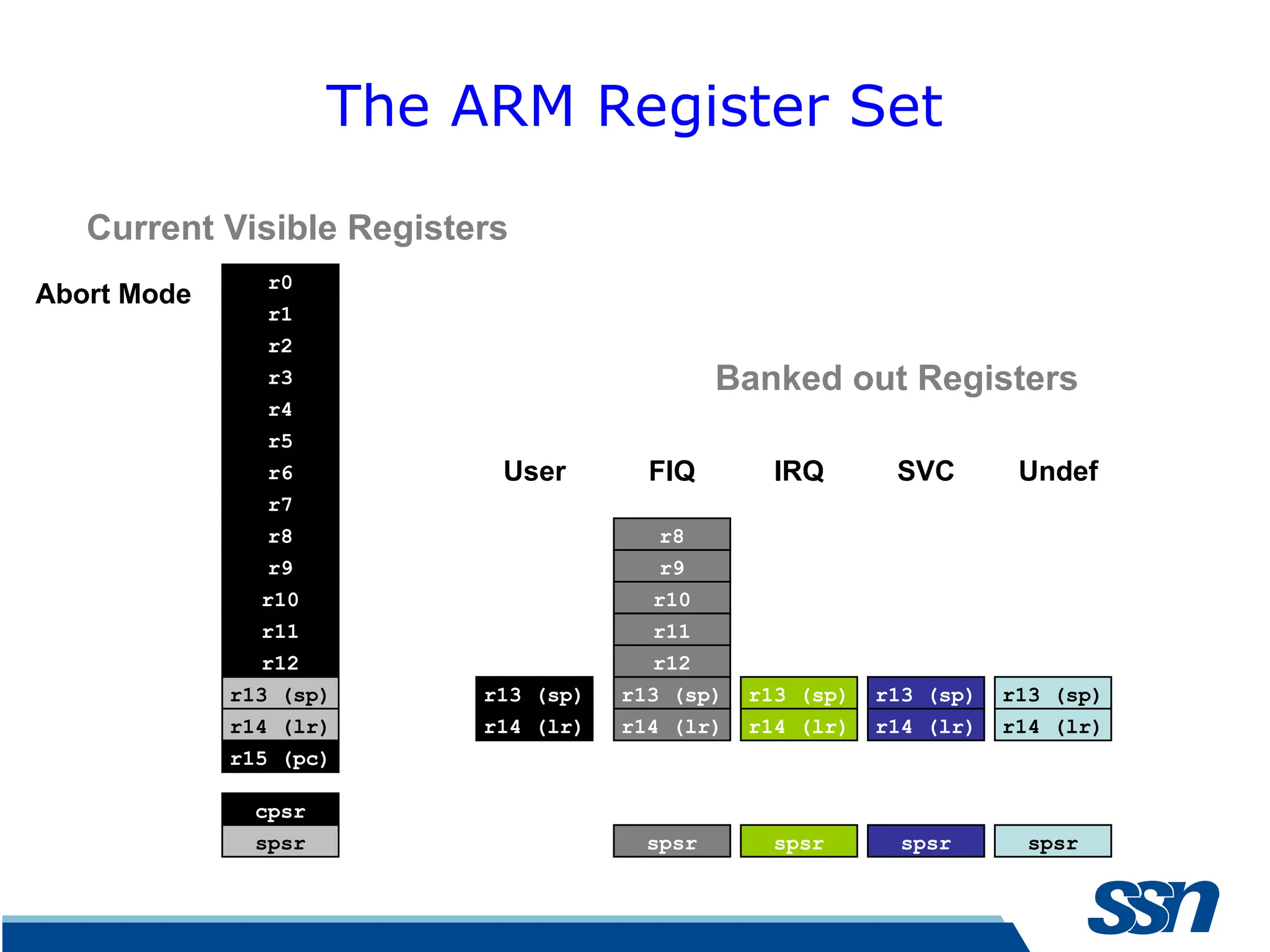
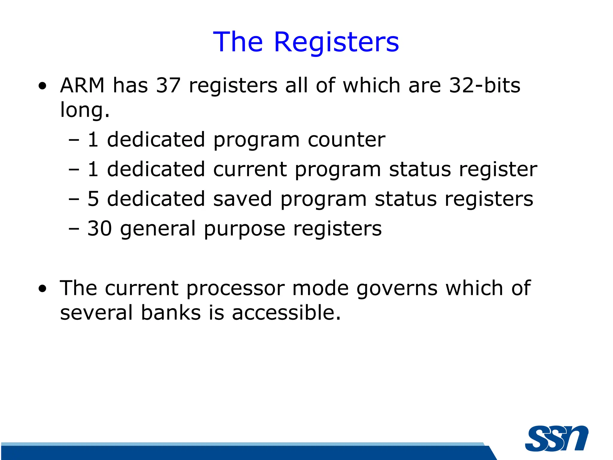
The Registers • ARMhas 37 registers all of which are 32-bits long. – 1 dedicated program counter – 1 dedicated current program status register – 5 dedicated saved program status registers – 30 general purpose registers • The current processor mode governs which of several banks is accessible.
20.
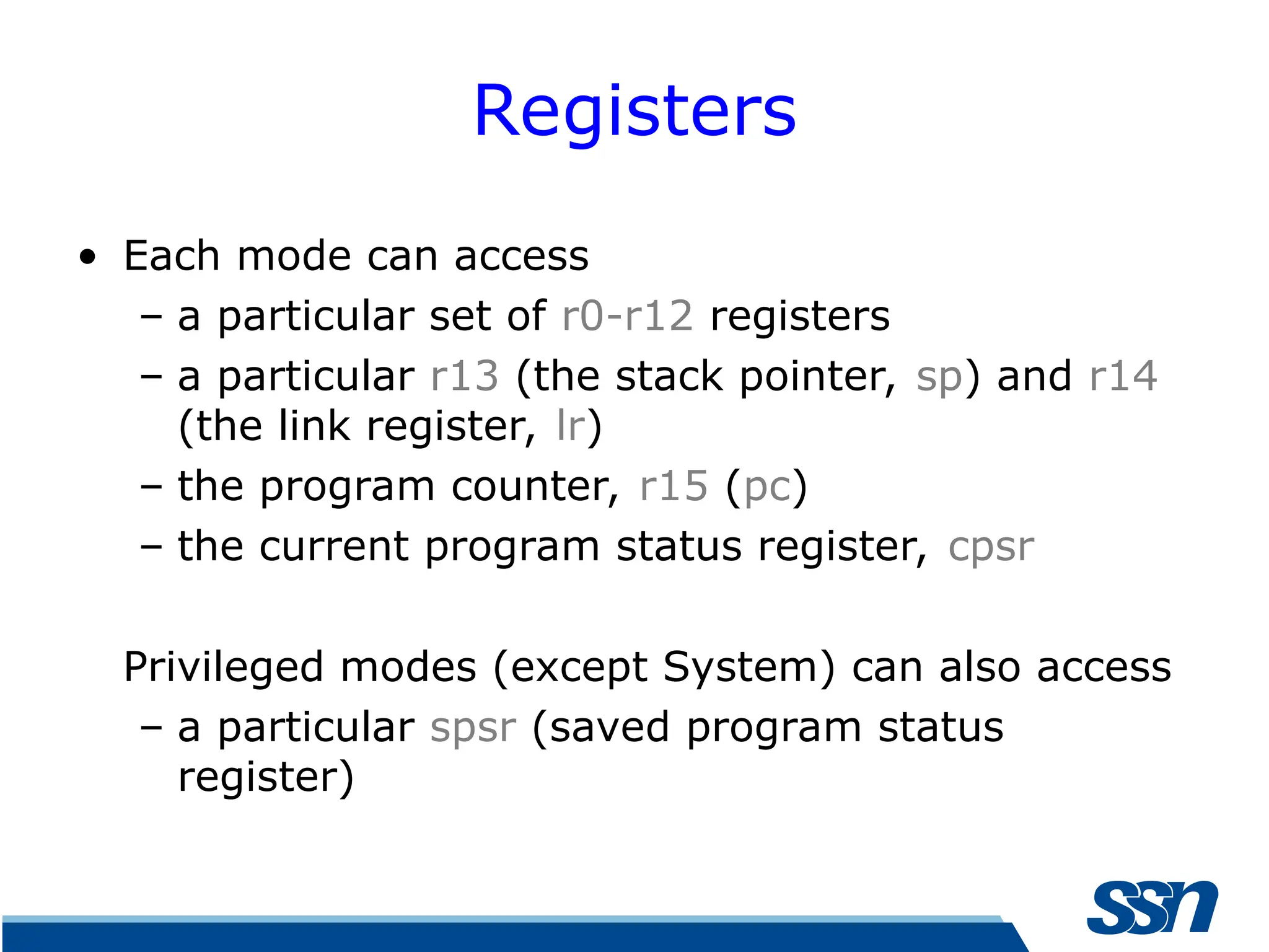
Registers • Each modecan access – a particular set of r0-r12 registers – a particular r13 (the stack pointer, sp) and r14 (the link register, lr) – the program counter, r15 (pc) – the current program status register, cpsr Privileged modes (except System) can also access – a particular spsr (saved program status register)
21.
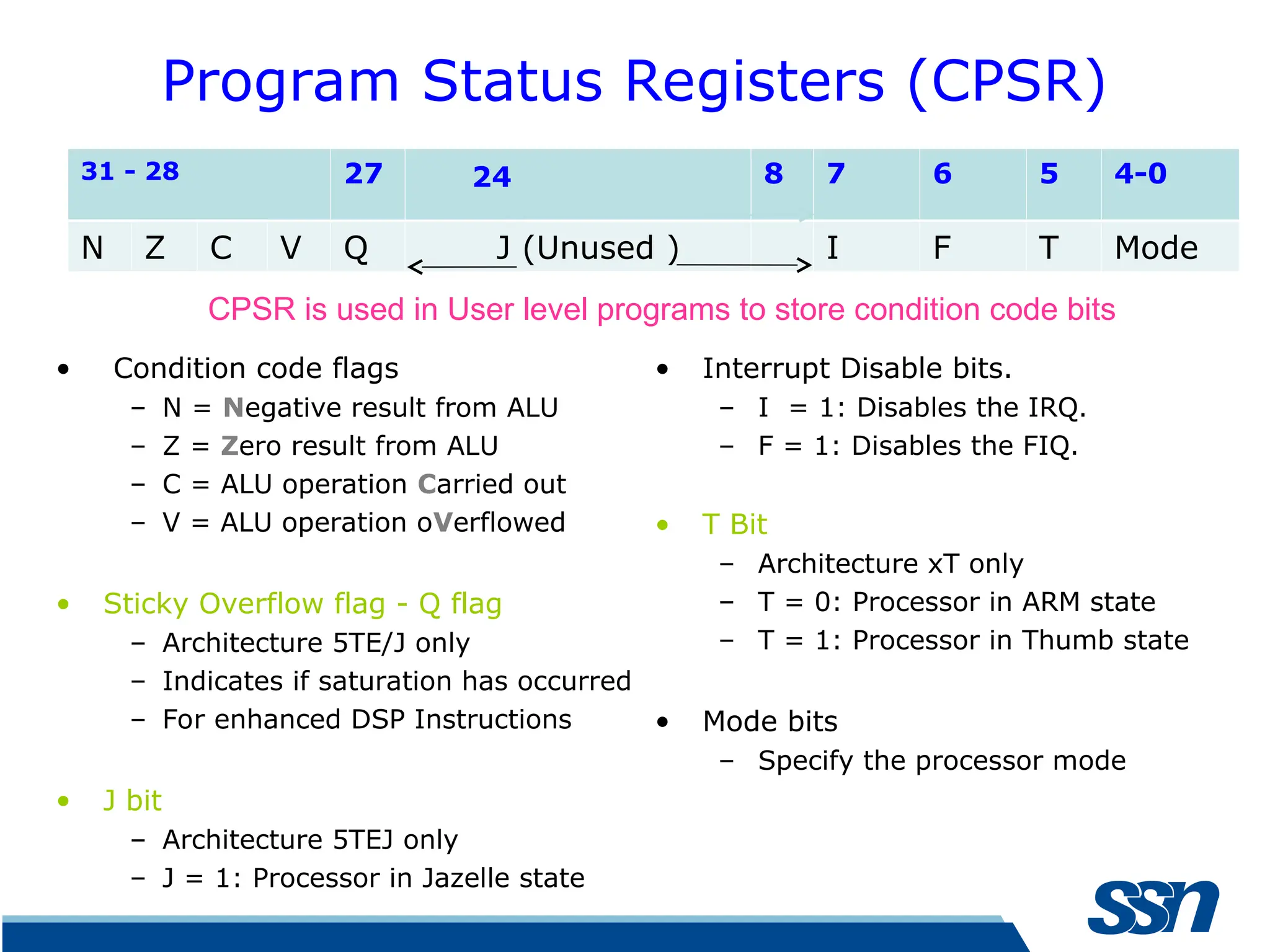
Program Status Registers(CPSR) • Condition code flags – N = Negative result from ALU – Z = Zero result from ALU – C = ALU operation Carried out – V = ALU operation oVerflowed • Sticky Overflow flag - Q flag – Architecture 5TE/J only – Indicates if saturation has occurred – For enhanced DSP Instructions • J bit – Architecture 5TEJ only – J = 1: Processor in Jazelle state • Interrupt Disable bits. – I = 1: Disables the IRQ. – F = 1: Disables the FIQ. • T Bit – Architecture xT only – T = 0: Processor in ARM state – T = 1: Processor in Thumb state • Mode bits – Specify the processor mode 31 - 28 27 24 8 7 6 5 4-0 N Z C V Q J (Unused ) I F T Mode CPSR is used in User level programs to store condition code bits
22.
Processor states • Whenthe processor is executing in ARM state: – All instructions are 32 bits wide – All instructions must be word aligned – Therefore the pc value is stored in bits [31:2] with bits [1:0] undefined (as instruction cannot be half-word or byte aligned). • When the processor is executing in Thumb state: – All instructions are 16 bits wide – All instructions must be half-word aligned – Therefore the pc value is stored in bits [31:1] with bit [0] undefined (as instruction cannot be byte aligned).
23.
Processor states • Whenthe processor is executing in Jazelle state: – All instructions are 8 bits wide – Processor performs a word access to read 4 instructions at once
24.
Summary • The variousArchitectural profiles of ARM processor are studied • Principal features with Register set of ARM familiarized
References • Marilyn Wolf,Computers as Components: Principles of Embedded Computing System Design, Morgan Kaufmann Publishers, Third Edition, 2012 • Steve Furber, ARM System-chip-Architecture, Pearson, Second Edition, 2011
Editor's Notes
#14 The cause of confusion here is the term “word” which will mean 16-bits to people with a 16-bit background. In the ARM world 16-bits is a “halfword” as the architecture is a 32-bit one, whereas “word” means 32-bits. There are actually three instruction sets in modern ARM cores (such as the version 7 cores – A8, M3, and R4, and even the M1): you have Thumb, Thumb2 and ARM. One core in particular, the M3, executes only Thumb2 code, not ARM. All the instructions are 16 bits. Java bytecodes are 8-bit instructions designed to be architecture independent. Jazelle transparently executes most bytecodes in hardware and some in highly optimized ARM code. This is due to a tradeoff between hardware complexity (power consumption & silicon area) and speed.
#17 This animated slide shows the way that the banking of registers works. On the left the currently visible set of registers are shown for a particular mode. On the right are the registers that are banked out whilst in that mode. Each key press will switch mode: user -> FIQ ->user -> IRQ -> user ->SVC -> User -> Undef -> User -> Abort and then back to user. The following slide then shows this in a more static way that is more useful for reference
#19 The ARM architecture provides a total of 37 registers, all of which are 32-bits long. However these are arranged into several banks, with the accessible bank being governed by the current processor mode. We will see this in more detail in a couple of slides. In summary though, in each mode, the core can access: a particular set of 13 general purpose registers (r0 - r12). a particular r13 - which is typically used as a stack pointer. This will be a different r13 for each mode, so allowing each exception type to have its own stack. a particular r14 - which is used as a link (or return address) register. Again this will be a different r14 for each mode. r15 - whose only use is as the Program counter. The CPSR (Current Program Status Register) - this stores additional information about the state of the processor: And finally in privileged modes, a particular SPSR (Saved Program Status Register). This stores a copy of the previous CPSR value when an exception occurs. This combined with the link register allows exceptions to return without corrupting processor state.
#21 Green psr bits are only in certain versions of the ARM architecture ALU status flags (set if "S" bit set, implied in Thumb state). Sticky overflow flag (Q flag) is set either when saturation occurs during QADD, QDADD, QSUB or QDSUB, or the result of SMLAxy or SMLAWx overflows 32-bits Once flag has been set can not be modified by one of the above instructions and must write to CPSR using MSR instruction to cleared PSRs split into four 8-bit fields that can be individually written: Control (c) bits 0-7 Extension (x) bits 8-15 Reserved for future use Status (s) bits 16-23 Reserved for future use Flags (f) bits 24-31 Bits that are reserved for future use should not be modified by current software. Typically, a read-modify-write strategy should be used to update the value of a status register to ensure future compatibility. Note that the T/J bits in the CPSR should never be changed directly by writing to the PSR (use the BX/BXJ instruction to change state instead). However, in cases where the processor state is known in advance (e.g. on reset, following an interrupt, or some other exception), an immediate value may be written directly into the status registers, to change only specific bits (e.g. to change mode). New ARM V6 bits now shown.
#22 ARM is designed to efficiently access memory using a single memory access cycle. So word accesses must be on a word address boundary, halfword accesses must be on a halfword address boundary. This includes instruction fetches. Point out that strictly, the bottom bits of the PC simply do not exist within the ARM core - hence they are ‘undefined’. Memory system must ignore these for instruction fetches. In Jazelle state, the processor doesn’t perform 8-bit fetches from memory. Instead it does aligned 32-bit fetches (4-byte prefetching) which is more efficient. Note we don’t mention the PC in Jazelle state because the ‘Jazelle PC’ is actually stored in r14 - this is technical detail that is not relevant as it is completely hidden by the Jazelle support code.

![Processor states • When the processor is executing in ARM state: – All instructions are 32 bits wide – All instructions must be word aligned – Therefore the pc value is stored in bits [31:2] with bits [1:0] undefined (as instruction cannot be half-word or byte aligned). • When the processor is executing in Thumb state: – All instructions are 16 bits wide – All instructions must be half-word aligned – Therefore the pc value is stored in bits [31:1] with bit [0] undefined (as instruction cannot be byte aligned).](https://image.slidesharecdn.com/arm-introductionregistersandprocessorstates-250327034956-a7d6ebf6/75/ARM-Introduction-registers-and-processor-states-ppt-22-2048.jpg)