Paper presents a real-time system for recognizing human activities through motion analysis using an FPGA and Handel-C. It includes a user-friendly GUI for FPGA programming and emphasizes the stages of detection, classification, and behavior understanding. Various detection methods and hardware implementations are explored to achieve effective motion detection and recognition.
![Indonesian Journal of Electrical Engineering and Informatics (IJEEI) Vol. 5, No. 1, March 2017, pp. 44~58 ISSN: 2089-3272, DOI: 10.11591/ijeei.v5i1.261 44 Received October 25, 2016; Revised January 14, 2017; Accepted February 20, 2017 A Real-Time Implementation of Moving Object Action Recognition System Based on Motion Analysis Kamal Sehairi 1* , Cherrad Benbouchama 2 , Kobzili El Houari 2 , Chouireb Fatima 1 1 Laboratoire LTSS, Departement of Electrical Engineering, Université Amar Telidji Laghouat, Route de Ghardaia, Laghouat 03000, Algeria 2 Laboratoire LMR, École Militaire Polytechnique, Bordj El Bahri, Algeria e-mail: k.sehairi@lagh-univ.dz, sehairikamel@yahoo.fr Abstract This paper proposes a PixelStreams-based FPGA implementation of a real-time system that can detect and recognize human activity using Handel-C. In the first part of our work, we propose a GUI programmed using Visual C++ to facilitate the implementation for novice users. Using this GUI, the user can program/erase the FPGA or change the parameters of different algorithms and filters. The second part of this work details the hardware implementation of a real-time video surveillance system on an FPGA, including all the stages, i.e., capture, processing, and display, using DK IDE. The targeted circuit is an XC2V1000 FPGA embedded on Agility’s RC200E board. The PixelStreams-based implementation was successfully realized and validated for real-time motion detection and recognition. Keywords: from papermoving object, recognition system, FPGA, real-time system, motion detection 1. Introduction In modern society, there is a growing need for technologies such as video surveillance and access control to detect and identify human and vehicle motion in various situations. Intelligent video surveillance attempts to assist human operators when the number of cameras exceeds the operators’ capability to monitor them and alerts the operators when abnormal activity is detected. Most intelligent video surveillance systems are designed to detect and recognize human activity. It is difficult to define abnormal activity because there are many behaviors that can represent such activity. Examples include a person entering a subway channel, abandonment of a package, a car running in the opposite direction, and people fighting or rioting. However, it is possible not only to set criteria to detect abnormal activity but also to zoom in on the relevant area to facilitate the work of the operator. In general, an intelligent video surveillance system has three major stages: detection, classification, and activity recognition [1]. Over the years, various methods have been developed to deal with issues in each stage. 2. Related Work Many methods for motion detection have already been proposed. They have been classified [1]–[3] into three major categories: background subtraction, [4],[5] temporal differencing [6] , [7] and optical flow[8],[9]. Further, motion detection methods have been recently classified into matching methods, energy-based methods, and gradient methods. The aim of the motion detection stage is to detect regions corresponding to moving objects such as vehicles and human beings. It is usually linked to the classification stage in order to identify moving objects. There are two main types of approaches for moving object classification:[1],[2],[10] shape-based identification and motion-based classification. Different descriptions of shape information of motion regions such as representations of points, boxes, silhouettes, and blobs are available for classifying moving objects. For example, Lipton et al.[11] used the dispersedness and area of image blobs as classification metrics to classify all moving object blobs into human beings, vehicles, and clutter. Further, Ekinci et al.[12] used silhouette- based shape representation to distinguish humans from other moving objects, and the skeletonization method to recognize actions. In motion-based identification, we are more interested in detecting periodic, non-rigid, articulated human motion . For example, Ran et](https://image.slidesharecdn.com/064dec1625octkamaledited-171224035542/75/A-Real-Time-Implementation-of-Moving-Object-Action-Recognition-System-Based-on-Motion-Analysis-1-2048.jpg)
![IJEEI ISSN: 2089-3272 A Real-Time Implementation of Moving Object Action Recognition… (Kamal Sehairi) 45 al.[13] examined the periodic gait of pedestrians in order to track and classify it. The final stage of surveillance involves behavior understanding and activity recognition. Various techniques for this purpose have been categorized into seven types: dynamic time warping algorithms, finite state machines, hidden Markov models, time-delay neural networks, syntactic techniques, non- deterministic finite automata, and self-organizing neural networks. Such a wide variety of techniques is attributable to the complexity of the problems and the extensive research conducted in this field. The computational complexity of these methods and the massive amount of information obtained from video streams makes it difficult to achieve real-time performance on a general-purpose CPU or DSP. There are four main architectural approaches for overcoming this challenge: application-specific integrated circuits (ASICs) and field- programmable gate arrays (FPGAs), parallel computing, GPUs, and multiprocessor architectures. Evolving high-density FPGA architectures, such as those with embedded multipliers, memory blocks, and high I/O (input/output) pin counts, are ideal solutions for video processing applications [14]. In the field of image and video processing, there are many FPGA implementations for motion segmentation and tracking. For example, Menezes et al. [5] used background subtraction to detect vehicles in motion, targeting Altera’s Cyclone II FPGA with Quartus II software. Another similar study on road traffic detection [15] adopted the sum of absolute differences (SAD) algorithm, implemented on Agility’s RC300E board using an XC2V6000 FPGA with Handel-C and the PixelStreams library of Agility’s DK Design Suite. Other methods for motion detection such as optical flow have been successfully implemented [8],[9] on an FPGA. For example, Ishii et al.[8] optimized an optical flow algorithm to process 1000 frames per second. The algorithm was implemented on a Virtex-II Pro FPGA. Many video surveillance systems have been developed for behavior change detection. For example, in the framework of ADVISOR, a video surveillance system for metro stations, a finite state machine (with scenarios) [16] is used to define suspicious behavior (jumping over a barrier, overcrowding, fighting, etc.). The W4 system [17] is a system for human activity recognition that has been implemented on parallel processors with a resolution of 320×240. This system can detect objects carried by people and track body parts using background detection and silhouettes. Bremond and Morioni [18] extracted the features of moving vehicles to detect their behaviors by setting various scenario states (toward an endpoint, stop point, change in direction, etc.); the application employs aerial grayscale images. The objective of this study is to implement different applications of behavior change detection and moving object recognition based on motion analysis and the parameters of moving objects. Such applications include velocity change detection, direction change detection, and posture change detection. The results can be displayed in the RGB format using chains of parallelized sub-blocks. We used Handel-C and the PixelStreams library of Agility’s DK Design Suite to simplify the acquisition and display stages. An RC200E board with an embedded Virtex-II XC2V1000 FPGA was employed for the implementation. 3. Mixed Software-Hardware Design To make our implementation more flexible, we use the software-hardware platform approach. This approach simplifies not only the use of the hardware but also the change between soft data and hard data, especially for image processing applications that need many parameters to be changed, for example, the parameters of convolution filters and threshold levels. In our implementation, we use Handel-C for the hardware part. Handel-C is a behavior- oriented programming language for FPGA hardware synthesis, and it is adapted to the co- design concept [19]. The software part is developed using Visual C++. After generating the bit file using Agility’s DK Design Suite, [20] we use our software interface to load this bit file via the parallel port (with a frequency of 50 MHz) on the RC200E board in order to configure the FPGA. The algorithm parameters are transferred through this port as 8-bit data at the same frequency. For the user, these operations are hidden. The graphical user interface allows the user to configure/erase the FPGA and change the algorithm parameters. For example, in our case, we can change the threshold level according to the brightness of the scene or the velocity level according to the object in motion (human, vehicle).](https://image.slidesharecdn.com/064dec1625octkamaledited-171224035542/75/A-Real-Time-Implementation-of-Moving-Object-Action-Recognition-System-Based-on-Motion-Analysis-2-2048.jpg)
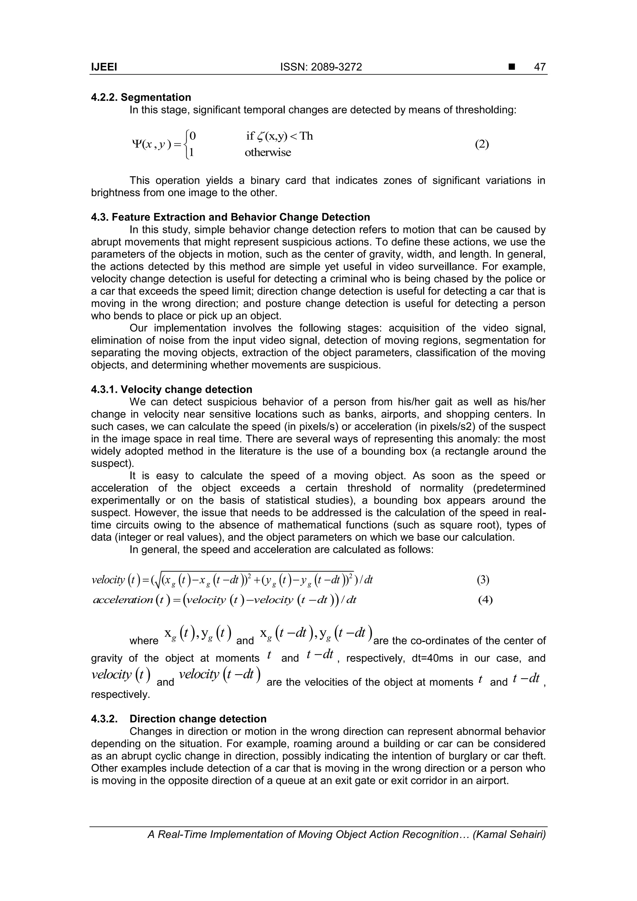
![ ISSN: 2089-3272 IJEEI Vol. 5, No. 1, March 2017 : 44 – 58 46 4. Outline of the Algorithm 4.1. Pixel Streams Library Before we detail and explain our algorithm and the method used to achieve our goals, we should discuss the tools used for our implementation. We used an RC200E board with an embedded XC2V1000 FPGA [21]. This board has multiple video inputs (S-video, camera video, and composite video), multiple video outputs (VGA, S-video, and composite video), and two ZBT SRAMs, each with a capacity of 2 MB. The language used is Handel-C [22] and the integrated development environment (IDE) is Agility’s DK5. This environment is equipped with different platform development kits (PDKs) that include the PixelStreams library [23]. The PixelStreams library is used to develop systems for image and video processing. It includes many blocks (referred to as filters) that perform primary video processing tasks such as acquisition, stream conversion, and filtering. The user has to associate these blocks carefully by indicating the type of the stream (pixel type, coordinate type, and synchronization type). Then, the user can generate the algorithm in Handel-C. Thereafter, the user has to add or modify blocks to program his/her method, and finally, he/she must merge the results. It is worth mentioning that these blocks are parameterizable, i.e., we can modify the image processing parameters, such as the size of the acquired image or the threshold. These blocks are fully optimized and parallelized. Figure 1 shows the GUI of PixelStreams. Figure 1. PixelStreams GUI 4.2. Detection Algorithm We choose to implement the delta frame method for three reasons: its adaptability to changes in luminance, its simplicity, and its low consumption of hardware resources. This method determines the absolute difference between two successive images, and it is executed in two stages: temporal difference and segmentation. 4.2.1. Temporal difference In this stage, we determine the absolute difference between the previous frame and the current frame as follows. , 1 1 ( , ) ( , ) ( , ) ( , ) ( , ) (1)t t t t dI x y x y x y I x y I x y dt where ( , )x y is the difference between It(x,y) (i.e., the intensity of pixel (x,y) at moment t) and It-1(x,y) (i.e., the intensity of pixel (x,y) at moment t-1).](https://image.slidesharecdn.com/064dec1625octkamaledited-171224035542/75/A-Real-Time-Implementation-of-Moving-Object-Action-Recognition-System-Based-on-Motion-Analysis-3-2048.jpg)
![ ISSN: 2089-3272 IJEEI Vol. 5, No. 1, March 2017 : 44 – 58 50 After calculating the min and max values along the two axes, we determine the center of gravity of the detected object. We calculate the sum of the pixel co-ordinates that have non- zero values along the x- and y-axes, and we divide these coordinate values by their sum. However, for our implementation, it is better to avoid this division. Therefore, we use the direct method. We subtract the max from the min and divide the result by 2. Division by 2 is achieved by a simple bit shift (right shift). Once the values minX, MaxX, minY, MaxY, and XG, YG are obtained, we copy these values into the behavior change detection block. Then, we reset these values to zero. 5.3. Behavior Change Detection Block As stated in the previous section, the analysis block provides the behavior change detection block with the parameters of the moving objects. In this stage, we save the values extracted from the first delta frame (xg(t-1), yg(t-1), minx(t-1), MaxX(t-1), miny(t-1), MaxY(t-1)), and from the second delta frame, we obtain the current values xg(t), yg(t), minx(t), MaxX(t), miny(t), and MaxY(t). From these latter results, we can calculate the width and length of the moving object to classify the object as human, vehicle, or others, as in our previous work [24]. Using the values extracted in two different instants (t-1, t), we define the changes in behavior. For velocity change detection, the speed and acceleration are calculated using the two equations presented in Sec. 4.4.1. However, we simplify these equations by calculating the absolute differences between two moments (the previous and current values). If the absolute difference exceeds a certain threshold Vth, we assume that the velocity has changed, and we copy the values of the center of gravity in the display block in order to draw a rectangle around the object. Then, the current values are saved as previous values. Consider a practical problem that involves the values of the center of gravity. In our algorithm, we need to reset all the variables to zero. Consequently, the coordinates of the center of gravity will be zero. If an object enters the scene, the coordinates of the center of gravity change from 0 to xg, yg, and this will cause false detection. To overcome this problem, we have to ensure that the object has entered the scene entirely. For this purpose, we set a condition on the coordinates of the bounding box for two consecutive instants; if this condition is met (|minXt1 - minXt2 | > S AND |MaxXt1 - MaxXt2 | > S), we can guarantee that the object has entered the scene entirely, either from the right or from the left. Figure 6. False velocity change detection (the object enters the scene). Table 1. Solution proposed for false velocity change detection.](https://image.slidesharecdn.com/064dec1625octkamaledited-171224035542/75/A-Real-Time-Implementation-of-Moving-Object-Action-Recognition-System-Based-on-Motion-Analysis-7-2048.jpg)
![IJEEI ISSN: 2089-3272 A Real-Time Implementation of Moving Object Action Recognition… (Kamal Sehairi) 57 Figure 15 shows our graphical user interface (GUI), which is divided into four sections. Three of these sections are used to detect just one simple behavior each, whereas the fourth section detects all the behaviors. Using this GUI, we can send the bit-file for configuring or erasing our FPGA, or directly changing the filter parameters without the need to use the IDE. Figure 15. Graphical user interface. 7. Conclusions We presented a mixed software-hardware approach that simplifies the use of the hardware part by enabling us to communicate with it using the graphical interface. In addition, it simplifies the choice of the algorithm to be implemented and modifies the parameters of this algorithm. We adopted the proposed approach for object detection and behavior recognition based on motion analysis and sudden movements. We exploited the hardware part, which offers the possibility of handling large amounts of data and performing calculations for image processing via parallel processing, guaranteed by the use of the PixelStreams library of Agility’s DK Design Suite. Further, we tried to improve our architecture by collecting all the different behaviors using a single program. In addition, we added warning messages using the PxsConsole filter. Thus, we successfully implemented different algorithms that can recognize objects in motion and detect changes in velocity, direction, and posture in real time. The results showed that our approach achieves good recognition and detection of these behaviors, especially in indoor areas. However, in outdoor areas, the results are less promising owing to the simple motion detection algorithm used; this problem is aggravated by occlusion due to overlapping movements of different persons. Therefore, in the future, we will try to use multiple cameras (stereoscopic, Kinect) with improved motion detection and learning methods to detect behavior changes in crowded environments. Acknowledgements We would like to thank Pr. Larbes Cherif and Dr. Benkouider Fatiha for their insightful comments. References [1] L Wang, W Hu, and T Tan. Recent developments in human motion analysis. Pattern Recogn. 2003; 36(3): 585-601. [2] W Hu, T Tan, L Wang, and S Maybank. A survey on visual surveillance of object motion and behaviors. IEEE T Syst Man Cyb. 2004; 34(3). [3] T Ko. A survey on behavior analysis in video surveillance for homeland security applications. Washington DC: AIPR. 2008.](https://image.slidesharecdn.com/064dec1625octkamaledited-171224035542/75/A-Real-Time-Implementation-of-Moving-Object-Action-Recognition-System-Based-on-Motion-Analysis-14-2048.jpg)
![ ISSN: 2089-3272 IJEEI Vol. 5, No. 1, March 2017 : 44 – 58 58 [4] M Piccardi. Background subtraction techniques: a review. IEEE SMC. 2004; 4: 3099-3104. [5] GGS Menezes and AG Silva-Filho. Motion detection of vehicles based on FPGA. SPL VI Southern. 2010: 151-154. [6] W Shuigen, C Zhen, L Ming, and Z Liang. An improved method of motion detection based on temporal difference. ISA 2009. 2009: 1-4. [7] Widyawan, MI Zul, and LE Nugroho. Adaptive motion detection algorithm using frame differences and dynamic template matching method. URAI 2012. 2012: 236-239. [8] I Ishii, T Taniguchi, K Yamamoto, and T Takaki. 1000 fps real-time optical flow detection system. Proc. SPIE 7538. 2010. 75380M. [9] J Diaz, E Ros, F Pelayo, EM Ortigosa, and S Mota. FPGA-based real-time optical-flow system. IEEE T Circ Syst Vid. 2006; 16(2): 274-279. [10] M Paul, S Haque, and S Chakraborty. Human detection in surveillance videos and its applications - a review. EURASIP JASP. Springer International Publishing. 2013. [11] AJ Lipton, H Fujiyoshi, and RS Patil. Moving target classification and tracking from real-time video. WACV 98. 1998: 8-14. [12] M Ekinci and E Gedikli. Silhouette based human motion detection and analysis for real-time automated video surveillance. Turk. J. Elec. Eng. & Comp. Sci. 2005; 13: 199-229. [13] Y Ran, I Weiss, Q Zheng, and LS Davis. Pedestrian detection via periodic motion analysis. Int J Comput Vision. 2007; 71(2): 143-160. [14] K Ratnayake and A Amer. An FPGA-based implementation of spatio-temporal object segmentation. Proc. ICIP. 2006: 3265-3268. [15] M Gorgon, P Pawlik, M Jablonski, and J Przybylo. FPGA-based road traffic videodetector. DSD 2007. [16] F Cupillard , A Avanzi , F Bremond, and M Thonnat. Video understanding for metro surveillance. ICNSC 2004. [17] I Haritaoglu, D Harwood, and LS Davis. W4: Real-time surveillance of people and their activities. IEEE T Pattern Anal. 2000; 22 (8): 809-830. [18] F Bremond and G Medioni. Scenario recognition in airborne video imagery. IUW 1998. 1998: 211- 216. [19] M Edwards and B Fozard. Rapid prototyping of mixed hardware and software systems. DSD 2002. 2002: 118-125. [20] “Agility DK User Manual”, Mentor Graphics Agility (2012), http://www.mentor.com/products/fpga/handel-c/dk-design-suite/ [21] Virtex II 1.5v Field-Programmable Gate Arrays. Data sheet, Xilinx Corporation, 2001. [22] DK5 Handel-C language reference manual. Agility 2007. [23] “PixelStreams Manual”, Mentor Graphics Agility (2012), http://www.mentor.com/products/fpga/handel-c/pixelstreams/ [24] K Sehairi, C Benbouchama, and F Chouireb. Real Time Implementation on FPGA of Moving Objects Detection and Classification. International Journal of Circuits, Systems and Signal Processing. 2015: 9; 160-167.](https://image.slidesharecdn.com/064dec1625octkamaledited-171224035542/75/A-Real-Time-Implementation-of-Moving-Object-Action-Recognition-System-Based-on-Motion-Analysis-15-2048.jpg)