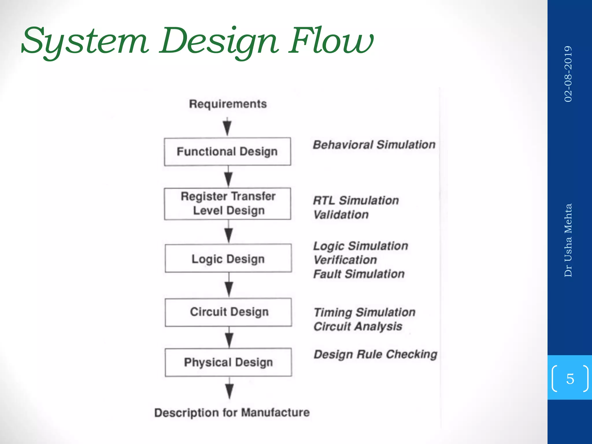
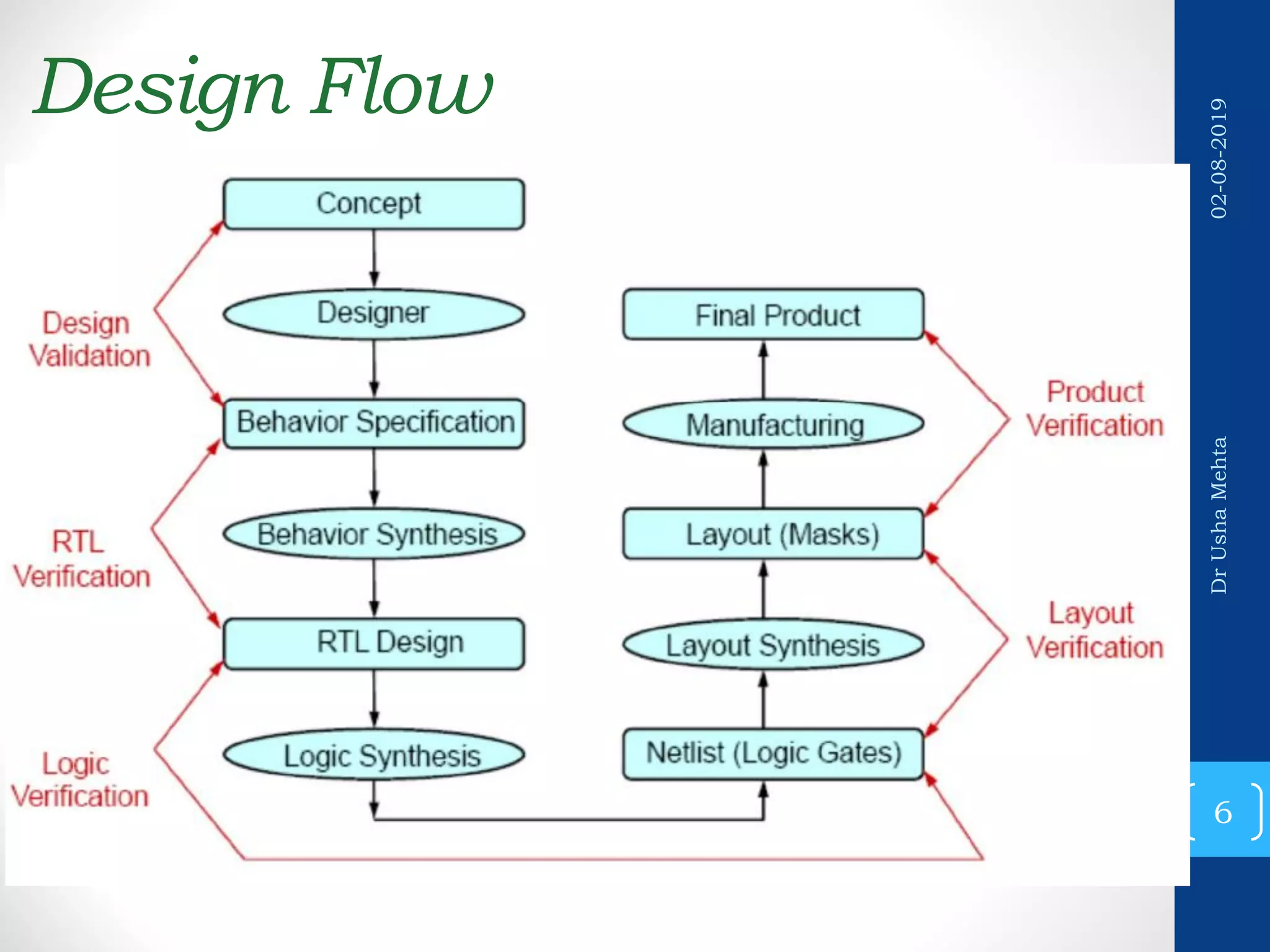
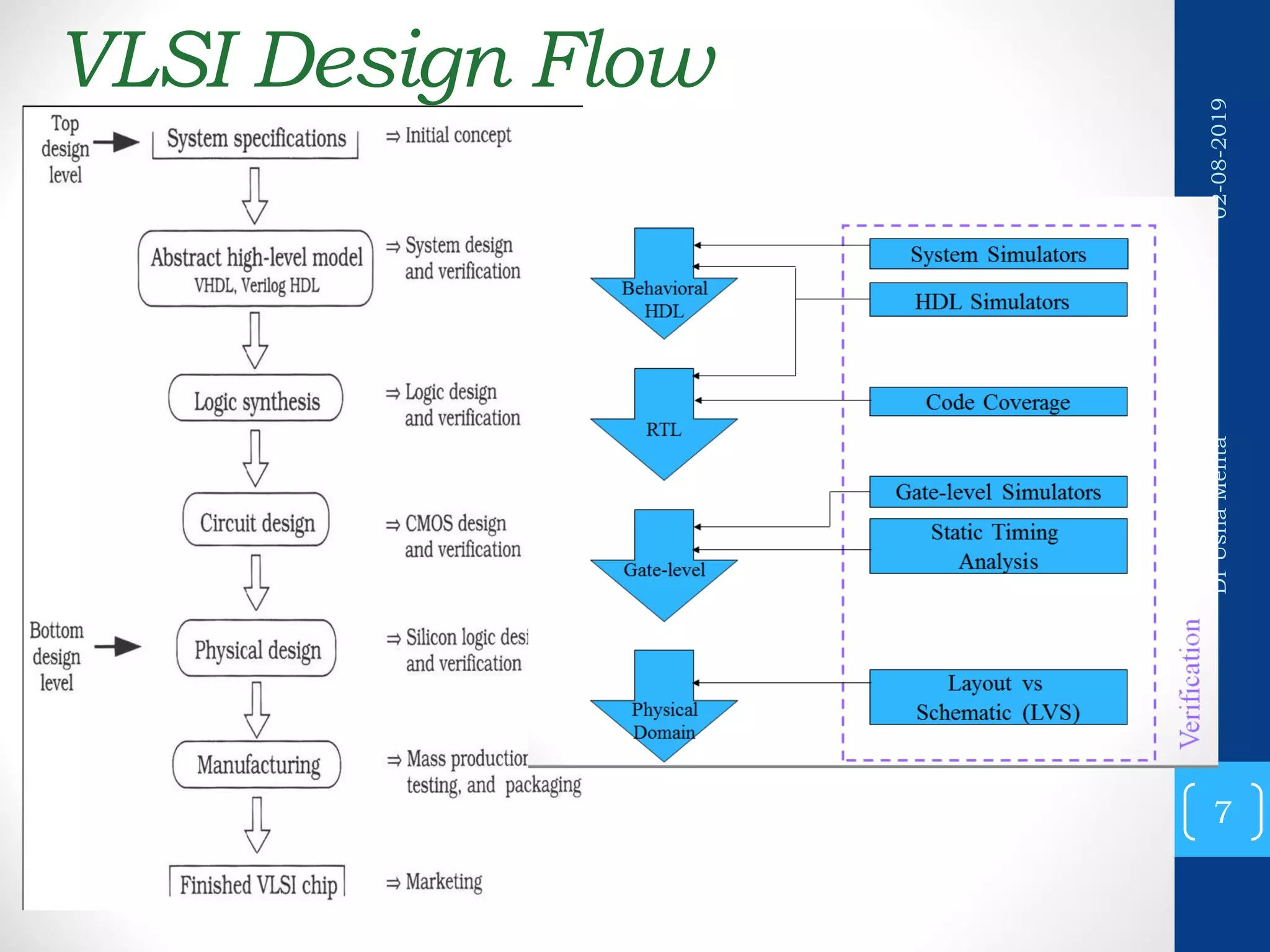
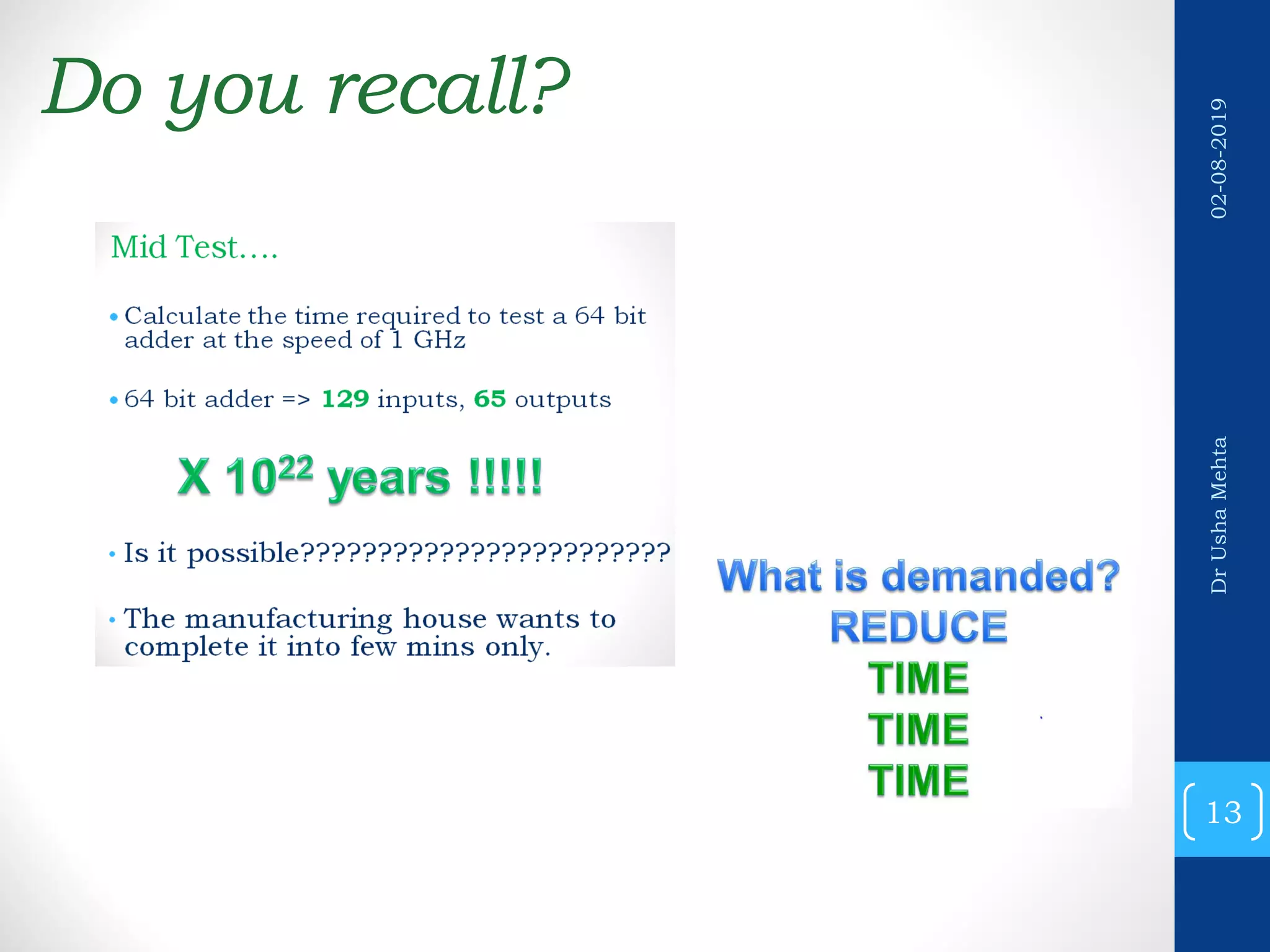
Downloaded 94 times
![Directed Input Generator • module adder(a,b,c); //DUT code start input [15:0] a; input [15:0] b; output [16:0] c; assign c = a + b; endmodule //DUT code end module top(); //TestBench code start reg [15:0] a; reg [15:0] b; wire [16:0] c; adder DUT(a,b,c); //DUT Instantiation initial begin a = 16'h45; //apply the stimulus b = 16'h12; #10 $display(" a=%0d,b=%0d,c=%0d",a,b,c); //send the output to terminal for visual inspection end endmodule //TestBench code end 25 DrUshaMehta02-08-2019](https://image.slidesharecdn.com/20192testingandverificationofvlsidesignverification-190802093131/75/2019-2-testing-and-verification-of-vlsi-design_verification-25-2048.jpg)
![Random Input Generation module adder(a,b,c); //DUT code start input [15:0] a,b; output [16:0] c; assign c = a + b; endmodule //DUT code end module top(); //TestBench code start reg [15:0] at; reg [15:0] bt; wire [16:0] ct; adder DUT(at,bt,ct); //DUT Instantiation initial repeat(100) begin a = $random; //apply random stimulus b = $random; #10 $display(" a=%0d,b=%0d,c=%0d",a,b,c); end endmodule //TestBench code end 27 DrUshaMehta02-08-2019](https://image.slidesharecdn.com/20192testingandverificationofvlsidesignverification-190802093131/75/2019-2-testing-and-verification-of-vlsi-design_verification-27-2048.jpg)
![Self Checking Test benches • module top(); //TB code start reg [15:0] a; reg [15:0] b; wire [16:0] c; adder DUT(a,b,c); //DUT Instantiation initial repeat(100) begin a = $random; //apply random stimulus b = $random; #10 $display(" a=%0d,b=%0d,c=%0d",a,b,c); if( a + b != c) // monitor logic. $display(" *ERROR* "); end endmodule //TB code end 31 DrUshaMehta02-08-2019](https://image.slidesharecdn.com/20192testingandverificationofvlsidesignverification-190802093131/75/2019-2-testing-and-verification-of-vlsi-design_verification-31-2048.jpg)
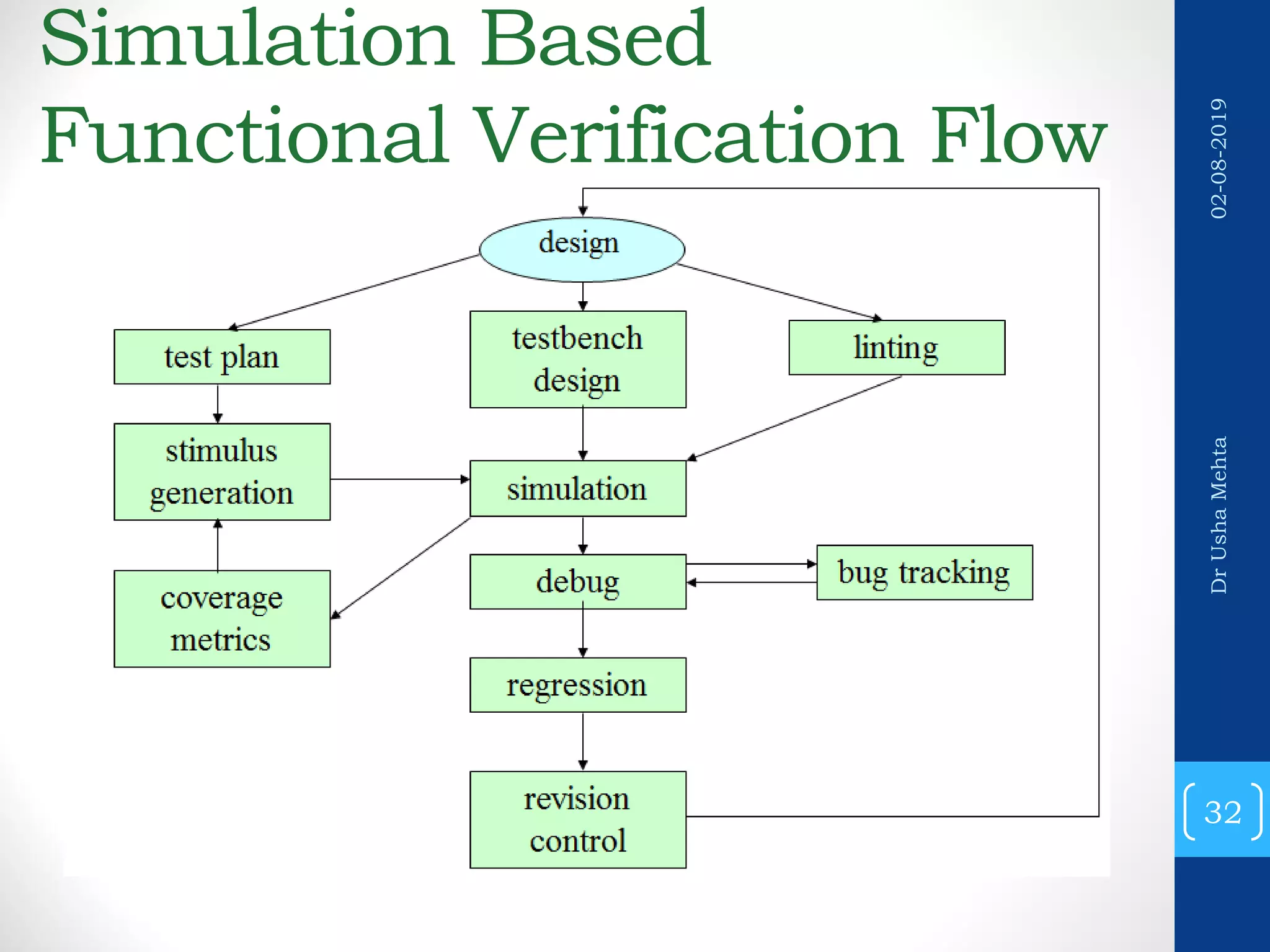


This document provides an introduction to verification of VLSI designs and functional verification. It discusses sources of errors in specifications and implementations, ways to reduce human errors through automation and mistake-proofing techniques. It also covers the reconvergence model of verification, different verification methods like simulation, formal verification and techniques like equivalence checking and model checking. The document then discusses verification flows, test benches, different types of test cases and limitations of functional verification.