 IoT Self-Watering System — Complete Build
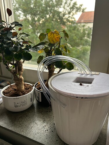
After about a week of tinkering, wiring, debugging, and finally getting the last AC adapter for the relays, my IoT self-watering system is complete and running reliably.
The setup combines soil-moisture sensors, water pumps, and a clean web interface so I can monitor and water plants automatically — or trigger pumps manually from anywhere on my network.
 Components Used
-
3× RUNCCI-YUN Mini Water Pumps
-
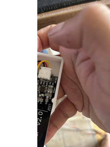
3× Hygrometer Module V2.0 Soil-Moisture Sensors
-
1× ICQUANZX 16-Channel Analog/Digital Multiplexer Breakout (removed later due to unstable signals)
-
Arduino Uno R4 WiFi
Soil-moisture sensors continuously sample soil conditions. -
The Arduino Uno R4 WiFi collects sensor data.
-
Based on thresholds, the corresponding relay switches on a pump to water the plant.
-
A Raspberry Pi web server provides real-time monitoring, manual overrides, and timing configuration.
This allows the setup to run unattended — but I can still take direct control when needed.
Notes on the Multiplexer
At first, I routed all soil-moisture sensors through a 16-channel multiplexer.
However, the readings became unstable and noisy.
Instead of spending time filtering signals, I removed the multiplexer and wired sensors directly to the Arduino.
This made the system much simpler and more reliable.
 Circuit Design
1. PCB / Schematic Diagram

- Arduino UNO R4 WiFi as the main controller
- Soil sensors → analog input
- Relays → digital pins controlling pumps
- LCD (LCM1602 IIC) via I2C
- Power supply shared between Arduino + pumps
2. Wiring / Breadboard Diagram
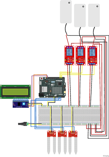
Shows the physical layout: Arduino on breadboard, relays connected to pumps, sensors wired directly, and an external supply powering everything.
 Web Interface
The browser dashboard displays pump states, soil readings, and lets me start/stop pumps on demand.

 Relays & Sensor Chassis
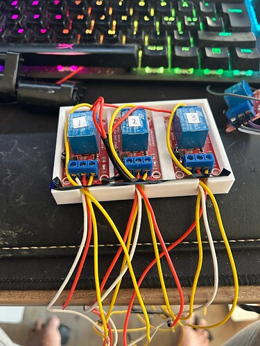
All relays used to switch the pumps:
Close-up of the 3D-printed chassis for soil-moisture sensors:
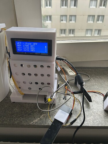
finally done…
I have video of it but dont know how to add them.