Pull up problems

Having read up about pull ups and pull downs I thought it would be a good idea to use a pull down resistor with an infra red sensor that I am using on a camera trap project.

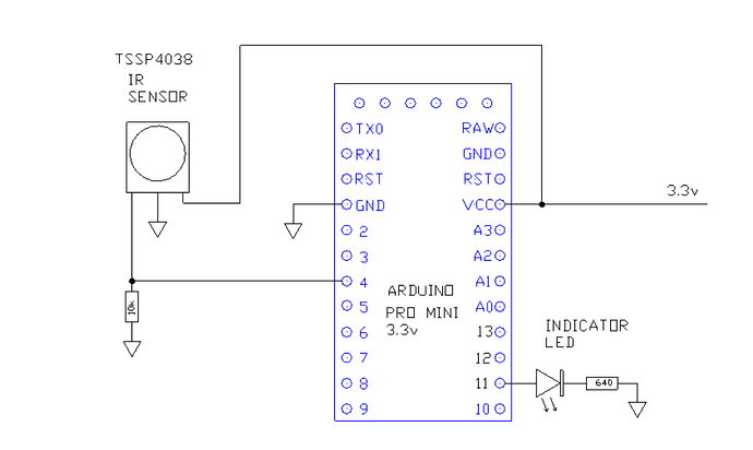
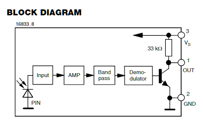
When the output from the sensor goes high as a break in the 38khz IR signal is detected pin 4 goes HIGH. This does indeed happen when there is no pull down resistor but when a pull down is used the voltage at Pin 4 reduces significantly.

With a 10k pull down resistor pin 4 goes to 0.72v

With a 56k pull down resistor pin 4 goes to 1.99v

With a 148k pull down resistor pin 4 goes to 2.58v

What am I doing wrong? Does the TSSP4038 even need a pull down reistor?

Extra info that may be useful.

I am using a LDO reglator to provide 3.3v because other components need that voltage too.

The output of the LDO seems is 2.237v rather than the expected 3.3v.

What led you to that conclusion ?

The purpose of pullup/pulldown resistors is to ensure that inputs to the Arduino are in a known state at all times and not floating at an unknown voltage, maybe HIGH, maybe LOW

I was told that I should install one by someone who knows more about electronics that me. I cant remember if it was on a forum or just someone that I met.

Are you saying that I dont need one?

I don't see any reason to use one. Did your mentor tell you why you should use one ?

I dont think my mentor told me anything like that, but even so, I still dont really understand why I do not need one. Does the sensor already provide a solid “already pulled down” LOW logic signal when a suitable IR signal is present?

Anyway, no pull down needed. Great news, many thanks.

I have to go out now but any new info n this subject will be greatfuly received and studied later.

Did you consult the datasheet? https://www.vishay.com/docs/82458/tssp40.pdf

It has an open collector output with internal 33k pull-up resistor. So you're creating a voltage divider.

3.3 * 10 / (10+33) = 0.77V
3.3 * 56 / (56+33) = 2.08V

Seems to match your results.

1 Like

I would go further and say that you should not have one.

2 Likes

And maybe ut is a good idea to connect tge middle leg to the analog input and the 3v3 keg to 3v3 and the gnd leg to gnd...
It has 3 legs for a reason...

I did see the block diagram but I am not experienced enough to realise that the resistor was a pull down resistor.

Thanks for pointing it out.

Because the sensor has a HIGH or LOW output I assumed that a digital input was the way to go. Are ther advantages in feeding it to an analog input?

As for the other 2 legs, they are routed exactly as you suggest arn’t they?

It's not a pull-down resistor, it's a pull-up resistor.

5 Likes

No, you should be using a digital input.
After all it has a digital output with two states, either it has received IR light or it hasn't received IR light.

Sorry for the confusion... use digital input!

Your schematic is correct, except for the 10K pulldown.
Remove it and everything will work.

The pro mini might act erratically at such a low voltage.

That seems quite low what else is connected and what LDO are you using?

The LDO I am using is the TC1262.

The other user of 3.3v is the RYLR998 radio module

The output voltage should be between 3.22V and 3.38V, so something is wrong somewhere.

Do you have capacitors on the input and output of the TC1262?
Are all the connections soldered?

What is the input voltage to the regulator?

I have 1uF caps on the input and output

Joinnts are breadboard only at the mo

Input voltage is 3.9V from a 18650 cell

AH!!!

Just realised that I wrote 2.237V. It should have been 3.237V.

So the TC1262 is within spec.

Sorry for the confusion.

No problem
Have fun!

I'd not be too sure!

Connect:
pin2 to ground
pin3 to +3.3
Pin 1 to D4

thats what its made for and the 33k IS a pull UP.
A pull DOWN is not useful in this applicatiojn

1 Like