Problem with invalid characters in the serial monitor

Hello to all Arduino fans (or Lora).

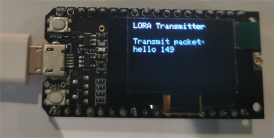
I am having a problem with invalid characters on the LoRa TTGO OLED. This problem only occurs on this device, on the Arduino Uno, everything is normal. The invalid characters only apply to LoRa on the Serial Monitor and when communicating with another device via jumper cable, which it receives with invalid characters. When something is displayed on the OLED screen, it does not look strange. (The image below already contains the code.)

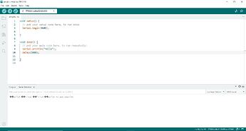
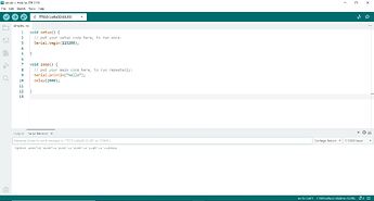
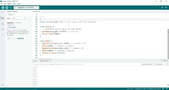
Here is the code when I use the OLED screen:

// Libraries for LoRa #include <SPI.h> #include <LoRa.h> #include "DHT.h" // Libraries for OLED Display #include <Wire.h> #include <Adafruit_GFX.h> #include <Adafruit_SSD1306.h> // Sensor pin and type #define DHTPIN 2 // Connect the DHT data pin to TTGO GPIO 2 #define DHTTYPE DHT11 // DHT 11 // Definitions for the TTGO LoRa32-OLED board #define SCK 5 #define MISO 19 #define MOSI 27 #define SS 18 #define RST 14 #define DIO0 26 #define BAND 866E6 // Use a frequência correta para sua região // Definitions for the OLED display #define OLED_SDA 4 #define OLED_SCL 15 #define OLED_RST 16 #define SCREEN_WIDTH 128 #define SCREEN_HEIGHT 64 Adafruit_SSD1306 display(SCREEN_WIDTH, SCREEN_HEIGHT, &Wire, OLED_RST); void setup() { Serial.begin(9600); // Configure the OLED display pinMode(OLED_RST, OUTPUT); digitalWrite(OLED_RST, LOW); delay(20); digitalWrite(OLED_RST, HIGH); Wire.begin(OLED_SDA, OLED_SCL); if(!display.begin(SSD1306_SWITCHCAPVCC, 0x3c, false, false)) { Serial.println("OLED display allocation failed!"); for(;;); } display.clearDisplay(); display.setTextColor(WHITE); display.setTextSize(1); display.setCursor(0,0); display.println("Initializing..."); display.display(); // Configure LoRa SPI.begin(SCK, MISO, MOSI, SS); LoRa.setPins(SS, RST, DIO0); if (!LoRa.begin(BAND)) { Serial.println("LoRa initialization failed!"); while (1); } Serial.println("LoRa OK!"); } void loop() { display.clearDisplay(); display.setCursor(0,0); display.println("Hello lora ttgo"); display.display(); delay(9000); } 

Here is the photo:

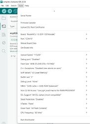
I have already tried changing the Serial frequency, checking if it matched the one selected in Arduino IDEA (baud rate), I added a delay after serial begin, changed the display modes in the Serial monitor (Carriage return, New Line, No line ending, Both), I have already changed the Upload Speed to be slower, I have already replaced the USB cable, and I even installed the CP210x USB to UART Bridge VCP driver. I used it on another computer with Windows 11, installed and uninstalled the Arduino IDE, and yes, I have already visited that forum to look for solutions. A friend suggested me that it could be the absence of the BOM that indicates the text formatting. When transmitting data, they appeared without corruption on both OLED screen.

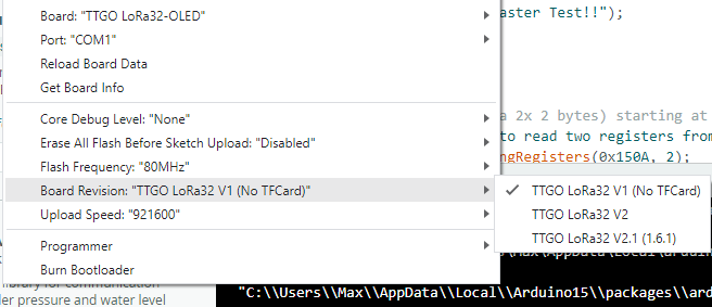
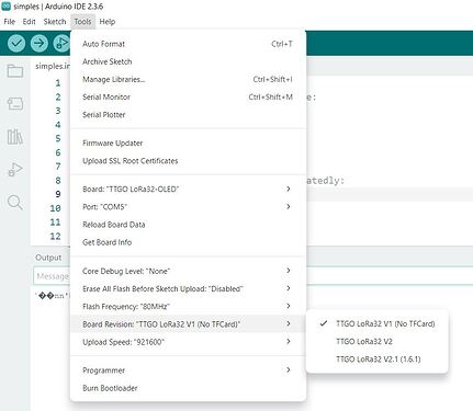
This seems to be a new problem that has been found. I am counting on your kindness to try to solve it. Here is more information:

Board Info:
BN: LilyGo T-Display
VID: 0X1A68
PID: 0X55D4
SN: 531C007448

Computer Info:
Windows 10
AMD processor

Hi! Welcome to the Forum.

Have you enabled USB CDC on Boot?

The LilyGo TTGO LoRa32 SX1276 OLED is a regular ESP32. It has no USB CDC functionality.

The schematics (https://github.com/Xinyuan-LilyGO/LilyGo-LoRa-Series/blob/master/schematic/T3_V1.6.1.pdf) show a CP2104 doing the USB-to-UART conversion. The ESP32 pins it connects to, U0TXD and U0RXD are also not connected to anything else.

First of all, with an ESP32, you should pretty much always use Serial.begin(115200);, not 9600. The 115200 baud is the bootloader baud. So if you mismatch this, you will always get garbage at every upload / restart in the beginning.

Also, if the bootloader complains (or hangs), you won't see the messages properly if you're not at 115200 baud. Due to e.g. power issues, you might need to press the reset button once after upload.

Other than that, I would recommend to install the latest drivers for the CP2104 from the official website

https://www.silabs.com/software-and-tools/usb-to-uart-bridge-vcp-drivers?tab=downloads

Try both the CP210x VCP Windows drivers (execute CP210xVCPInstaller_x64.exe) inside there and the CP210x Universal Windows Driver (you will need to use the Windows Device manager -> Right click on the USB COM port -> Update driver -> Search for drivers on my computer -> path to extraced folder with search subfolder). Replug your USB cable each time between them, close and reopen the serial monitor cleanly each time. Reboot your computer in between as needed.

Well, but the IDE screenshot in post #1 says IDE is configured to (and recognizes) a LiLyGo T-Display board. Also confirmed later on the board info description. This one is supposed to have an ESP32 S3 processor.

In the other hand, I agree that the picture of the board, also in post #1 seems to show another model

The picture definitely shows a TTGO LoRa32 SX1276 OLED and not a T-Display.

They should select this board instead

There's even different revisions available.

1 Like

Once again, thank you for the tips, but it still didn't work. I installed the CP210x VCP Windows drivers, CP210x Windows drivers, and even the CP210x Windows drivers with Serial Enumerator, as you can see in the printout. (even though one of the options does not appear, I remember having installed it)

I tested it at 115200 baud by setting the serial monitor to this frequency, and changed the Revision board as maxgerhardt suggested for the 3 possible options

I pressed the buttons on the Lora TTGO OLED to restart and apply the update, and I restarted the computer, but the Lora TTGO OLED did not show any message about the update. Was it really updated?

That is not enough. Serial monitor baud rate must match the one on the line:

Serial.begin(xxxxx); 

Also you need to upload the code again after changing the board to TTGO LoRa32.

By the way, I don’t think you’ll see anything on the OLED unless you upload a sketch that tells the board to write something on it.

What happens now when you upload the 2 different codes that are in post#1?

A lot of messing around when the issue is almost certainly your Serial. begin(9600) mismatch with the Baud of 115200. Set the baud to 9600 and see what happens.

OK guys,
I have already tested setting the serial monitor to the baud rate that is in the code on each screen print.


Don't rush, this problem seems to be unique.

I have a similar module labelled Heltek V2 with the same OLED and SX1276 pinout as your module

this code works OK (using Tools>Board Heltek WiFi LoRa V2)

// Heltek ESP32 LoRa V2 SX1276 LoRaReceiver // Tools>Board>Heltek WiFi LoRa V2 /* original code from Rui Santos Complete project details at https://RandomNerdTutorials.com/ttgo-lora32-sx1276-arduino-ide/ *********/ //Libraries for LoRa #include <SPI.h> #include <LoRa.h> //Libraries for OLED Display #include <Wire.h> #include <Adafruit_GFX.h> #include <Adafruit_SSD1306.h> //define the pins used by the SX1276 LoRa transceiver module #define SCK 5 #define MISO 19 #define MOSI 27 #define SS 18 #define RST 14 #define DIO0 26 //433E6 for Asia //866E6 for Europe //915E6 for North America #define BAND 866E6 //OLED pins #define OLED_SDA 4 #define OLED_SCL 15 #define OLED_RST 16 #define SCREEN_WIDTH 128 // OLED display width, in pixels #define SCREEN_HEIGHT 64 // OLED display height, in pixels Adafruit_SSD1306 display(SCREEN_WIDTH, SCREEN_HEIGHT, &Wire, OLED_RST); String LoRaData; void setup() { //initialize Serial Monitor Serial.begin(115200); delay(2000); //reset OLED display via software pinMode(OLED_RST, OUTPUT); digitalWrite(OLED_RST, LOW); delay(20); digitalWrite(OLED_RST, HIGH); //initialize OLED Wire.begin(OLED_SDA, OLED_SCL); if (!display.begin(SSD1306_SWITCHCAPVCC, 0x3c, false, false)) { // Address 0x3C for 128x32 Serial.println(F("SSD1306 allocation failed")); for (;;) ; // Don't proceed, loop forever } display.clearDisplay(); display.setTextColor(WHITE); display.setTextSize(1); display.setCursor(0, 0); display.print("\n\nLoRa32 SX1276 transmitter "); display.display(); Serial.println("\n\nLoRa32 SX1276 Transmitter Test"); //SPI LoRa pins SPI.begin(SCK, MISO, MOSI, SS); //setup LoRa transceiver module LoRa.setPins(SS, RST, DIO0); if (!LoRa.begin(BAND)) { Serial.println("Starting LoRa failed!"); while (1) ; } Serial.println("LoRa Initializing OK!"); display.setCursor(0, 10); display.println("LoRa Initializing OK!"); display.display(); } void loop() { static int counter = 0; Serial.print("Sending packet: "); char loraData[100] = { 0 }; // send packet LoRa.beginPacket(); sprintf(loraData, "hello %d", counter); //LoRa.print("hello "); LoRa.print(loraData); LoRa.endPacket(); Serial.println(loraData); delay(500); // Dsiplay information display.clearDisplay(); display.setCursor(0, 0); display.print("LORA Transmitter"); display.setCursor(0, 20); display.print("Transmit packet:"); display.setCursor(0, 30); display.printf("hello %d", counter); display.display(); counter++; } 

serial monitor displays

LoRa32 SX1276 Transmitter Test LoRa Initializing OK! Sending packet: hello 0 Sending packet: hello 1 Sending packet: hello 2 Sending packet: hello 3 Sending packet: hello 4 Sending packet: hello 5 Sending packet: hello 6 Sending packet: hello 7 Sending packet: hello 8 Sending packet: hello 9 Sending packet: hello 10 Sending packet: hello 11 Sending packet: hello 12 Sending packet: hello 13 Sending packet: hello 14 

EDIT: the above code also works also works on LilyGo T-Display select Tools> Board LilyGo T-Display

serial monitor output

LoRa32 SX1276 Transmitter Test LoRa Initializing OK! Sending packet: hello 0 Sending packet: hello 1 Sending packet: hello 2 Sending packet: hello 3 Sending packet: hello 4 Sending packet: hello 5 Sending packet: hello 6 Sending packet: hello 7 Sending packet: hello 8 

LoRa P2P is working OK - Heltec ESP32 LoRa V2

I'm using these 2 boards manager links in Additional Boards Manager URLs

http://arduino.esp8266.com/stable/package_esp8266com_index.json
https://dl.espressif.com/dl/package_esp32_index.json

I was testing with other models, I tested with a Lolin NodeMCU V3 vemos.cc

First, I watched the driver installation tutorial:

Then I made the circuit to turn the LED on and off from the website:

(It's in Portuguese, yes, I'm Brazilian)

This is my code, to which I added a part to display on the screen, and it is working on this other model, without invalid characters.


It has not yet been resolved with the LoRa TTGO, but there are already clues about the problem. Why did it work correctly on this other similar device? Knowing this may help to resolve the issue.

for ESP32 Additional Boards Manager URLs I used

https://espressif.github.io/arduino-esp32/package_esp32_index.json 

which came from installing Arduino-ESP32 support.