.
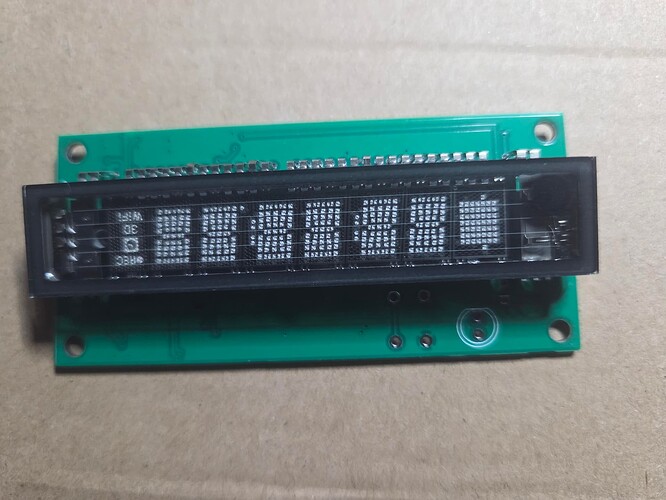
I'm always on the look out for interesting displays which can be used for clocks and was happy to find a Futaba 7-bt-317nk on aliexpress recently which appears to come from a surplus lot originally intended for video recorders on similar home entertainment devices.
It is a modified version of the standard 16 segment "starburst" pattern but with an additional 5 segments.
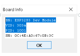
It has the unusual feature of including an indicator to signal that WiFi is available and a clock dial symbol which I have used to indicate that a recent time synchronisation has occurred. The hardware design was partly inspired by https://spritesmods.com/?art=vfdcontroller particularly the creative use of an ancient series CD4094 shift registers which can handle the 15 volts or so required to drive the display. The filament voltage (I'm using 2.7v) is provided from 5v dropped by three silicon diodes in series. The MCU is an ESP32-C3 Supermini which is soldered directly to the PCB (no filled copper zones under the antenna). The 15volts is derived from an SX1308 boost converter module (best set to the correct output voltage before soldering it to the PCB).
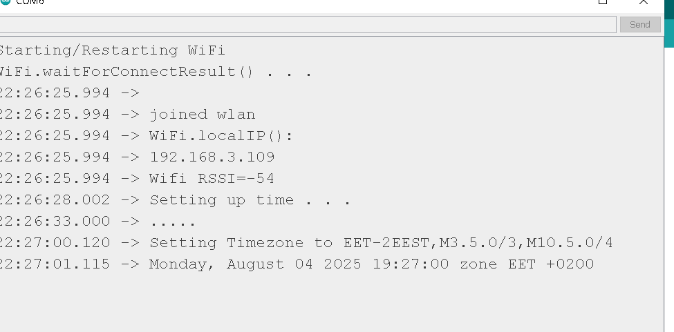
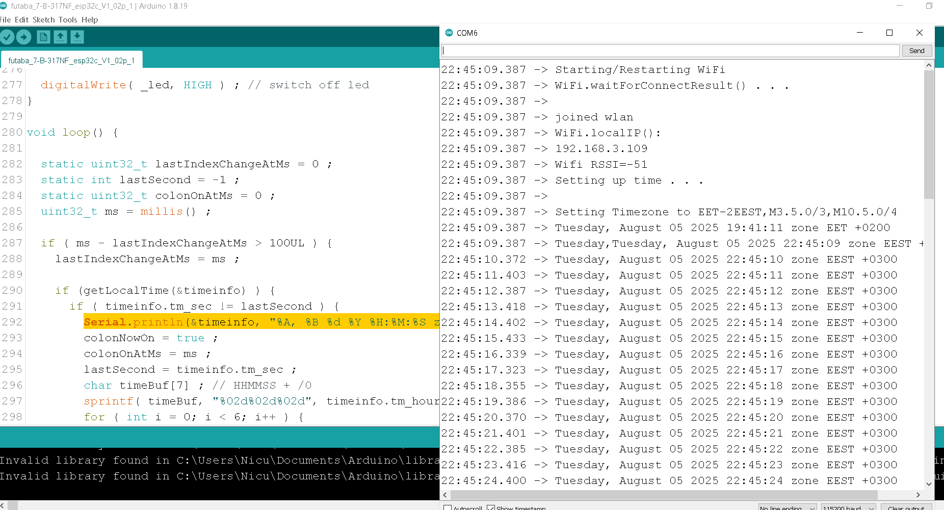
The software uses basic ESP32 native SNTP clock code (credits in the program). I plan later to use a better featured clock design where the configuration parameters (WLAN credentials, timezone etc.) can be updated by web browser using the ESP32's AP mode.
Anyway, here is the project including pictures, code and a schematic so anyone interested can duplicate it or use it as the basis of their own design.
Pictures

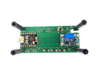

.
.
Schematic
VFD_Fatuba_ESP32SuperMini_clock.pdf (106.2 KB)
Code (Arduino ESP32 3.x compatible)
futaba_7_B_317NF_esp32c_V1_04p.ino (14.2 KB)
Gerbers/BoM
See post #7
Display supplier:
Try https://www.aliexpress.com/item/1005005876758913.html or search for "Futaba 7-bt-317nk"