The document describes an experiment to interface an LED and switch with an STM32 microcontroller, where the LED is controlled by the switch using the STM32. It discusses the components used, including the STM32 microcontroller, LED, button, resistors, and programming tools. The procedure involves designing the circuit in Proteus, writing code in STM32CubeMX to control the LED based on the button state, and simulating the circuit behavior.
LABORATORY REPORT EMBEDDED SYSTEMDESIGN USING ARM CORTEX Course Code: CUTM1039 ELECTRICAL & ELECTROCNICS ENGINEERING SCHOOL OF ENGINEERING & TECHNOLOGY CENTURION UNIVERSITY OF TECHNOLOGY & MANAGEMENT RAMACHANDRAPUR, JATNI, KHURDA, BHUBANESWAR- 752050 Name: Hitesh Kumar Nath Regd. No.:200301150005 Section: “A” Branch: EEE Semester: 4th Semester
2.
EMBEDDED SYSTEM DESIGNUSING ARM CORTEX LAB MANUAL 2 | P a g e COURSE NAME : Embedded System Design using ARM Cortex List of Experiments: 1. Familiarization of different IDE to program STM32F10 Micro-controller. 2. Interfacing LED with STM32 to generate LED patterns. 3. Interfacing switch and LED to control LEDs with digital sensor using STM32. 4. Interfacing LCD and LED to display and blinking LED using STM32. 5. Interfacing STM32 to blink built-in LED using Arduino IDE. 6. Interfacing STM32 with LED using Arduino IDE. 7. Interfacing STM32 with LED and switch using Arduino IDE. 8. Interfacing STM32 with buzzer and Switch using Arduino IDE. 9. Interfacing STM32 with 7 segment display using Arduino IDE. 10. Interfacing STM32 with LCD using Arduino IDE. 11. Interface STM32 with Keypad using Arduino IDE. 12. Interfacing STM32 with DC motor using Arduino IDE. 13. Interfacing STM32 with DHT11 and LCD using Arduino IDE. 14. Interfacing STM32 with PIR sensor using Arduino IDE. 15. Interfacing STM32 with IR sensor using Arduino IDE. 16. Interfacing STM32 with Relay module using Arduino IDE. 17. Interfacing STM32 with Servo motor using Arduino IDE. 18. Interfacing STM32 with Soil moisture using Arduino IDE. 19. Interfacing STM32 with Ultrasonic sensor using Arduino IDE. 20. Interfacing STM32 with GPS module using Arduino IDE. 21. Interfacing STM32 with Bluetooth module using Arduino IDE. 22. Interfacing STM32 with I2C LCD module using Arduino IDE.
3.
EMBEDDED SYSTEM DESIGNUSING ARM CORTEX LAB MANUAL 3 | P a g e INDEX Exp. No. Date Name of The Experiments Page No. Teacher’s Signature 01. 25-01-2022 Familiarization of different IDE to program STM32F10 Micro-controller. 5-11 02. 27-01-2022 Interfacing LED with STM32 to generate LED patterns. 12-17 03. 01-02-2022 Interfacing switch and LED to control LEDs with digital sensor using STM32. 18-24 04. 02-02-2022 Interfacing LCD and LED to display and blinking LED using STM32. 25-31 05. 03-02-2022 Interfacing STM32 to blink builtin LED using Arduino IDE. 32-35 06. 15-02-2022 Interfacing STM32 with LED using Arduino IDE. 36-41 07. 16-02-2022 Interfacing STM32 with LED and switch using Arduino IDE. 42-46 08. 17-02-2022 Interfacing STM32 with buzzer and Switch using Arduino IDE. 47-52 09. 22-02-2022 Interfacing STM32 with 7 segment display using Arduino IDE. 53-60 10. 23-02-2022 Interfacing STM32 with LCD using Arduino IDE. 61-65 11. 24-02-2022 Interface STM32 with Keypad using Arduino IDE. 66-74 12. 08-03-2022 Interfacing STM32 with DC motor using Arduino IDE. 75-79 13. 09-03-2022 Interfacing STM32 with DHT11 and LCD using Arduino IDE. 80-85 14. 10-03-2022 Interfacing STM32 with PIR sensor using Arduino IDE. 86-92
4.
EMBEDDED SYSTEM DESIGNUSING ARM CORTEX LAB MANUAL 4 | P a g e 15. 15-03-2022 Interfacing STM32 with IR sensor using Arduino IDE. 93-98 16. 16-03-2022 Interfacing STM32 with Relay module using Arduino IDE. 99-103 17. 17-03-2022 Interfacing STM32 with Servo motor using Arduino IDE. 104-108 18. 22-03-2022 Interfacing STM32 with Soil moisture using Arduino IDE. 109-114 19. 23-03-2022 Interfacing STM32 with Ultrasonic sensor using Arduino IDE. 115-120 20. 29-03-2022 Interfacing STM32 with GPS module using Arduino IDE. 121-126 21. 30-03-2022 Interfacing STM32 with Bluetooth module using Arduino IDE. 127-132 22. 05-04-2022 Interfacing STM32 with I2C module using Arduino IDE. 133-137
5.
EMBEDDED SYSTEM DESIGNUSING ARM CORTEX LAB MANUAL 5 | P a g e Experiment No. 01. Date: 25.01.2022 AIM OF THE EXPERIMENT: Familiarization of different IDE to program STM32F10 Micro-controller. COMPONENTS USED: Sl. No. Component/Equipment/Software Specification Quantity 01. STM32CubeIDE - - 02. STM32CubeMX - - 03. Keil uVision - - 04. Arduino IDE - - THEORY: STM32CubeIDE: STM32CubeIDE is ST’s first integrated development environment, and it serves as a reference to developers working on STM32 microcontrollers. Many use a toolchain from a third-party vendor, and we will continue to work with IAR, Keil, and others to ensure that they offer an exceptional experience to their users. STM32CubeIDE is a highly symbolic initiative because it provides a free and uniquely feature-rich environment to enthusiasts and professionals, thanks to the integration of tools like STM32CubeMX that enable a more efficient workflow.
6.
EMBEDDED SYSTEM DESIGNUSING ARM CORTEX LAB MANUAL 6 | P a g e STM32CubeMX: STM32CubeMX is a graphical tool that helps developers generate code that initializes a system. Users get an interface to configure the micro-controller’s pinout and resolve conflicts as well as set up hardware peripherals and middleware. They can also configure their clock tree and benefit from a wizard that automates specific calculations. Similarly, another utility sets up and tunes the DDR on systems with STM32MP1 MPUs. The tool also helps select the right MCU or MPU and download its software package. Hence, it’s very often the first step for developers looking to create an application. The tool is available in STM32CubeIDE or as a standalone download. Keil uVision: µVision is a window-based software development platform that combines a robust and modern editor with a project manager and make facility tool. It integrates all the tools needed to develop embedded applications including a C/C++ compiler, macro assembler, linker/locator, and a HEX file generator.
7.
EMBEDDED SYSTEM DESIGNUSING ARM CORTEX LAB MANUAL 7 | P a g e Arduino IDE: The Arduino IDE is an open-source software, which is used to write and upload code to the Arduino boards. The IDE application is suitable for different operating systems such as Windows, Mac OS X, and Linux. It supports the programming languages C and C++. Here, IDE stands for Integrated Development Environment. PROCEDURE: a. STM32CubeIDE: Step-1: Getting started with STM32 cube IDE in this environment we basically saw the page Step-2: Then we have to select the part number and click the next button.
8.
EMBEDDED SYSTEM DESIGNUSING ARM CORTEX LAB MANUAL 8 | P a g e Step-3: Then it asks to give the project name Step-3: After giving the project name it gives an environment and according to our project we have to fixed it.
9.
EMBEDDED SYSTEM DESIGNUSING ARM CORTEX LAB MANUAL 9 | P a g e b. STM32CubeMX Step-1: When we work with STM32CubeMX first it gives us below environment Here we have to click “Access to MCU Selector”. Step-2: After that it ask to give part number and after giving that it will creates a new project. c. Keil μVision Step-1: When we work on STM32CubeMx, it generates code in Keil μVision. Step-2: After that we write code of our projects. Step-3: And when we write the code we click on the build and rebuild button. Step-4: After clicking the button it’s a hex file of our projects.
10.
EMBEDDED SYSTEM DESIGNUSING ARM CORTEX LAB MANUAL 10 | P a g e d. Arduino IDE Step-1: First we have to open the Arduino IDE and paste the link in preference. Step-2: Then we have to installed the STM32 in board manager. Step-3: After installing we have to set our board in Tools. Step-4: After completion the process we able to write the code for STM32.
11.
EMBEDDED SYSTEM DESIGNUSING ARM CORTEX LAB MANUAL 11 | P a g e CONCLUSION: After learned about STM32CubeIDE, STM32CubeIDE, Keil uVision and Arduino IDE, I have familiarized with different IDE and it’s features to program STM32F10 Micro-controller. Also got to know about the advantages of use this IDE. Teacher’s Remark : Date of Submission: 27.01.2022 Students Signature : Hitesh Kumar Nath Regd. No. : 200301150005 Teacher’s Signature : Branch : EEE
12.
EMBEDDED SYSTEM DESIGNUSING ARM CORTEX LAB MANUAL 12 | P a g e Experiment No. - 02 Date: 27.01.2022 AIM OF THE EXPERIMENT: Interfacing LED with STM32 to generate LED patterns. COMPONENTS USED: Sl. No. Component/Equipment/Software Specification Quantity 01 STM32F103C6 32-bit,20KB RAM 1 02 LED 3 to 5v 2 03 RESISTOR 510 Ω 2 04 STM32CubeIDE For Programming - 05 PROTEUS For Circuit Design - THEORY: STM32F103C6: The STMicroelectronics STM32F103C6 is an ARM 32-bit Cortex-M3 Micro-controller, 72MHz, 32kB Flash, 10kB SRAM, PLL, Embedded Internal RC 8MHz and 32kHz, Real-Time Clock, Nested Interrupt Controller, Power Saving Modes, JTAG and SWD, 2 Synch. 16-bit Timers with Input Capture, Output Compare and PWM, 16-bit 6-ch Advanced Timer, 2 16-bit Watchdog Timers, SysTick Timer, SPI, I2C, 2 USART, USB 2.0 Full Speed Interface, CAN 2.0B Active, 2 12-bit 10-ch A/D Converter, Fast I/O Ports.
13.
EMBEDDED SYSTEM DESIGNUSING ARM CORTEX LAB MANUAL 13 | P a g e Proteus: Proteus is used to simulate, design and drawing of electronic circuits. It was invented by the Labcenter electronic. By using proteus you can make two-dimensional circuits designs as well. With the use of this engineering software, you can construct and simulate different electrical and electronic circuits on your personal computers or laptops. Designing of circuits on the proteus takes less time than practical construction of the circuit. The possibility of error is less in software simulation such as loose connection that takes a lot of time to find out connection’s problems in a practical circuit. Circuit simulations provide the main feature that some components of circuits are not practical then you can construct your circuit on proteus. Resistor: A resistor is a passive two-terminal electrical component that implements electrical resistance as a circuit element. In electronic circuits, resistors are used to reduce current flow, adjust signal levels, to divide voltages, bias active elements, and terminate transmission lines, among other uses.
14.
EMBEDDED SYSTEM DESIGNUSING ARM CORTEX LAB MANUAL 14 | P a g e PROCEDURE: Step-1: First of all, I have created a new project in Proteus and giving the project name. Step-2: After creating a new project I have selected the component which is used in my project. Step-3: Then I have connected all the components. Step-4: After that I have set the LED as digital and give the respective values to the resistor. Step-5: Then I changed the power configuration of the projects. Step-6: After that I have write the code in STM32CubeIDE and set the respective parameters. Step-7: After write the code I have paste the HEX file in the micro-controller in Proteus and click the run button. CODE: #include "main.h" void SystemClock_Config(void); static void MX_GPIO_Init(void); int main(void) { HAL_Init(); SystemClock_Config(); MX_GPIO_Init(); while (1) { HAL_GPIO_WritePin(GPIOB, GPIO_PIN_0, GPIO_PIN_SET); HAL_GPIO_WritePin(GPIOB, GPIO_PIN_1, GPIO_PIN_RESET); HAL_Delay(500); HAL_GPIO_WritePin(GPIOB, GPIO_PIN_0, GPIO_PIN_RESET); HAL_GPIO_WritePin(GPIOB, GPIO_PIN_1, GPIO_PIN_SET); HAL_Delay(500); }} void SystemClock_Config(void)
EMBEDDED SYSTEM DESIGNUSING ARM CORTEX LAB MANUAL 16 | P a g e { __disable_irq(); while (1) { } } void assert_failed(uint8_t *file, uint32_t line){ } OUTPUT:
17.
EMBEDDED SYSTEM DESIGNUSING ARM CORTEX LAB MANUAL 17 | P a g e CONCLUSION: After the completion of the Experiment, I have learned how to Interfacing LED with STM32 to generate LED patterns. Teacher’s Remark : Date of Submission: 01.02.2022 Students Signature : Hitesh Kumar Nath Regd. No.: 200301150005 Teacher’s Signature : Branch : EEE
18.
EMBEDDED SYSTEM DESIGNUSING ARM CORTEX LAB MANUAL 18 | P a g e Experiment No.- 03 Date: 01.02.2022 AIM OF THE EXPERIMENT: Interfacing switch and LED to control LEDs with digital sensor using STM32. COMPONENTS USED: Sl. No. Component/Equipment/Software Specification Quantity 01 STM32F103C6 32-bit,20KB RAM 1 02 LED 3-5 V 1 03 BUTTON - 1 04 RESISTOR 100Ω AND 10K 2 05 STM32CubeMX Development Tool - 06 PROTEUS Designing Tool - THEORY: STMicroelectronics' STM32F1 series of mainstream MCUs covers the needs of a large variety of applications in the industrial, medical and consumer markets. High performance with first- class peripherals and low-power, low-voltage operation is paired with a high level of integration at accessible prices with a simple architecture and easy-to-use tools. Typical applications include motor drives and application control, medical and handheld equipment, industrial applications, PLCs, inverters, printers, and scanners, alarm systems, video intercom, HVAC and home audio equipment. - LCD parallel interface, 8080/6800 modes - 5 V- tolerant I/Os - Timer with quadrature (incremental) encoder input - 96-bit unique ID.
19.
EMBEDDED SYSTEM DESIGNUSING ARM CORTEX LAB MANUAL 19 | P a g e Proteus: Proteus Design Suite (designed by Labcenter Electronics Ltd.) is a software tool set, mainly used for creating schematics, simulating Electronics & Embedded Circuits and designing PCB Layouts. Proteus ISIS is used by Engineering students & professionals to create schematics & simulations of different electronic circuits. PROCEDURE: Step-1: First of all, I have created a new project in proteus giving project name. Step-2: After creating a new project I have select the component which is used in my project. Step-3: Then I have connected all the components. Step-4: Then I have set LED as digital and give values to the pullup resistor. Step-5: After that I have changed the power configuration of the projects. Step-6: Then I have written the code using STM32CubeMX. Step-7: In STM32CudeMX I have MDK ARM and Generate code in Keil uVision. Step-8: After that I compile the code and generate Hex file. Step-9: Then I have pasted the HEX file in the micro-controller in Proteus.
20.
EMBEDDED SYSTEM DESIGNUSING ARM CORTEX LAB MANUAL 20 | P a g e CODE: #include "main.h" void SystemClock_Config(void); static void MX_GPIO_Init(void); int main(void) { HAL_Init(); SystemClock_Config(); MX_GPIO_Init(); while (1) { if(HAL_GPIO_ReadPin(BUTTON_GPIO_Port, BUTTON_Pin)==GPIO_PIN_RESET) HAL_GPIO_WritePin(LED_GPIO_Port, LED_Pin,GPIO_PIN_SET); else HAL_GPIO_WritePin(LED_GPIO_Port, LED_Pin,GPIO_PIN_RESET); } } void SystemClock_Config(void) { RCC_OscInitTypeDef RCC_OscInitStruct = {0}; RCC_ClkInitTypeDef RCC_ClkInitStruct = {0}; RCC_OscInitStruct.OscillatorType = RCC_OSCILLATORTYPE_HSI;
21.
EMBEDDED SYSTEM DESIGNUSING ARM CORTEX LAB MANUAL 21 | P a g e RCC_OscInitStruct.HSIState = RCC_HSI_ON; RCC_OscInitStruct.HSICalibrationValue = RCC_HSICALIBRATION_DEFAULT; RCC_OscInitStruct.PLL.PLLState = RCC_PLL_NONE; if (HAL_RCC_OscConfig(&RCC_OscInitStruct) != HAL_OK) { Error_Handler(); } RCC_ClkInitStruct.ClockType = RCC_CLOCKTYPE_HCLK|RCC_CLOCKTYPE_SYSCLK |RCC_CLOCKTYPE_PCLK1|RCC_CLOCKTYPE_PCLK2; RCC_ClkInitStruct.SYSCLKSource = RCC_SYSCLKSOURCE_HSI; RCC_ClkInitStruct.AHBCLKDivider = RCC_SYSCLK_DIV1; RCC_ClkInitStruct.APB1CLKDivider = RCC_HCLK_DIV1; RCC_ClkInitStruct.APB2CLKDivider = RCC_HCLK_DIV1; if (HAL_RCC_ClockConfig(&RCC_ClkInitStruct, FLASH_LATENCY_0) != HAL_OK) { Error_Handler(); } } static void MX_GPIO_Init(void) { GPIO_InitTypeDef GPIO_InitStruct = {0}; __HAL_RCC_GPIOC_CLK_ENABLE();
22.
EMBEDDED SYSTEM DESIGNUSING ARM CORTEX LAB MANUAL 22 | P a g e __HAL_RCC_GPIOD_CLK_ENABLE(); __HAL_RCC_GPIOA_CLK_ENABLE(); HAL_GPIO_WritePin(LED_GPIO_Port, LED_Pin, GPIO_PIN_SET); GPIO_InitStruct.Pin = BUTTON_Pin; GPIO_InitStruct.Mode = GPIO_MODE_INPUT; GPIO_InitStruct.Pull = GPIO_PULLUP; HAL_GPIO_Init(BUTTON_GPIO_Port, &GPIO_InitStruct); GPIO_InitStruct.Pin = LED_Pin; GPIO_InitStruct.Mode = GPIO_MODE_OUTPUT_PP; GPIO_InitStruct.Pull = GPIO_NOPULL; GPIO_InitStruct.Speed = GPIO_SPEED_FREQ_MEDIUM; HAL_GPIO_Init(LED_GPIO_Port, &GPIO_InitStruct); } void Error_Handler(void) { __disable_irq(); while (1) { } } void assert_failed(uint8_t *file, uint32_t line) { }
EMBEDDED SYSTEM DESIGNUSING ARM CORTEX LAB MANUAL 24 | P a g e CONCLUSION: After done the Experiment I have Learned about interfacing switch and LED to control LEDs with digital sensor using STM32. Teacher’s Remark : Date of Submission: 02.02.2022 Students Signature : Hitesh Kumar Nath Regd. No.: 200301150005 Teacher’s Signature : Branch: EEE
25.
EMBEDDED SYSTEM DESIGNUSING ARM CORTEX LAB MANUAL 25 | P a g e Experiment No. 04 Date: 02.02.2022 AIM OF THE EXPERIMENT: Interfacing LCD and LED to display and blinking LED using STM32. COMPONENTS USED: Sl. No. Component/Equipment/Software Specification Quantity 01 STM32F103C6 32-bit,20KB RAM 1 02 LED 3-5 V 3 03 LCD 16×2 1 04 STM32CubeMX Programming NA 05 PROTEUS Circuit Design NA THEORY: 16 × 𝟐 LCD: The term LCD stands for liquid crystal display. It is one kind of electronic display module used in an extensive range of applications like various circuits & devices like mobile phones, calculators, computers, TV sets, etc. These displays are mainly preferred for multi- segment light-emitting diodes and seven segments. The main benefits of using this module are inexpensive; simply programmable, animations, and there are no limitations for displaying custom characters, special and even animations, etc.
26.
EMBEDDED SYSTEM DESIGNUSING ARM CORTEX LAB MANUAL 26 | P a g e LED: The lighting emitting diode is a p-n junction diode. It is a specially doped diode and made up of a special type of semiconductors. When the light emits in the forward biased, then it is called a light-emitting diode. The LED includes two terminals namely anode (+) and the cathode (-). PROCEDURE: Step-1: I have created a new project in proteus by giving project name. Step-2: After creating a new project I have selected the component which is used in my project. Step-3: Then I have connected all the components. Step-4: After that I have set LED as digital. Step-5: Then I changed the power configuration of the projects. Step-6: After I have written the code using STM32CubeMX. Step-7: In STM32CudeMX I have MDK ARM and Generate code in Keil uVision. Step-8: After that I compiled the code and generate Hex file. Step-9: Then I have to paste the HEX file in the micro-controller in Proteus and click the run button.
27.
EMBEDDED SYSTEM DESIGNUSING ARM CORTEX LAB MANUAL 27 | P a g e CODE: #include "main.h" #include "lcd_txt.h" void SystemClock_Config(void); static void MX_GPIO_Init(void); int main(void) { HAL_Init(); SystemClock_Config(); MX_GPIO_Init(); lcd_init(); // Programm LCD lcd_puts(0,0,(int8_t*)"****LCD TEST****"); HAL_Delay(5000); lcd_clear(); while (1) { HAL_GPIO_WritePin(GPIOA,GPIO_PIN_1|GPIO_PIN_2|GPIO_PIN_3,1); HAL_Delay(1000); HAL_GPIO_WritePin(GPIOA,GPIO_PIN_1|GPIO_PIN_2|GPIO_PIN_3,0); HAL_Delay(500); } } void SystemClock_Config(void) {
28.
EMBEDDED SYSTEM DESIGNUSING ARM CORTEX LAB MANUAL 28 | P a g e RCC_OscInitTypeDef RCC_OscInitStruct = {0}; RCC_ClkInitTypeDef RCC_ClkInitStruct = {0}; RCC_OscInitStruct.OscillatorType = RCC_OSCILLATORTYPE_HSI; RCC_OscInitStruct.HSIState = RCC_HSI_ON; RCC_OscInitStruct.HSICalibrationValue = RCC_HSICALIBRATION_DEFAULT; RCC_OscInitStruct.PLL.PLLState = RCC_PLL_NONE; if (HAL_RCC_OscConfig(&RCC_OscInitStruct) != HAL_OK) { Error_Handler(); } RCC_ClkInitStruct.ClockType = RCC_CLOCKTYPE_HCLK|RCC_CLOCKTYPE_SYSCLK |RCC_CLOCKTYPE_PCLK1|RCC_CLOCKTYPE_PCLK2; RCC_ClkInitStruct.SYSCLKSource = RCC_SYSCLKSOURCE_HSI; RCC_ClkInitStruct.AHBCLKDivider = RCC_SYSCLK_DIV1; RCC_ClkInitStruct.APB1CLKDivider = RCC_HCLK_DIV1; RCC_ClkInitStruct.APB2CLKDivider = RCC_HCLK_DIV1; if (HAL_RCC_ClockConfig(&RCC_ClkInitStruct, FLASH_LATENCY_0) != HAL_OK) { Error_Handler(); } } static void MX_GPIO_Init(void)
29.
EMBEDDED SYSTEM DESIGNUSING ARM CORTEX LAB MANUAL 29 | P a g e { GPIO_InitTypeDef GPIO_InitStruct = {0}; __HAL_RCC_GPIOA_CLK_ENABLE(); __HAL_RCC_GPIOB_CLK_ENABLE(); HAL_GPIO_WritePin(GPIOA, GPIO_PIN_1|GPIO_PIN_2|GPIO_PIN_3, GPIO_PIN_RESET); HAL_GPIO_WritePin(GPIOB, GPIO_PIN_10|GPIO_PIN_11|GPIO_PIN_12|GPIO_PIN_13 |GPIO_PIN_14|GPIO_PIN_15, GPIO_PIN_RESET); GPIO_InitStruct.Pin = GPIO_PIN_1|GPIO_PIN_2|GPIO_PIN_3; GPIO_InitStruct.Mode = GPIO_MODE_OUTPUT_PP; GPIO_InitStruct.Pull = GPIO_NOPULL; GPIO_InitStruct.Speed = GPIO_SPEED_FREQ_LOW; HAL_GPIO_Init(GPIOA, &GPIO_InitStruct); GPIO_InitStruct.Pin = GPIO_PIN_10|GPIO_PIN_11|GPIO_PIN_12|GPIO_PIN_13 |GPIO_PIN_14|GPIO_PIN_15; GPIO_InitStruct.Mode = GPIO_MODE_OUTPUT_PP; GPIO_InitStruct.Pull = GPIO_NOPULL; GPIO_InitStruct.Speed = GPIO_SPEED_FREQ_LOW; HAL_GPIO_Init(GPIOB, &GPIO_InitStruct); } void Error_Handler(void) {
30.
EMBEDDED SYSTEM DESIGNUSING ARM CORTEX LAB MANUAL 30 | P a g e __disable_irq(); while (1) { } } void assert_failed(uint8_t *file, uint32_t line) { } CIRCUIT DIAGRAM:
31.
EMBEDDED SYSTEM DESIGNUSING ARM CORTEX LAB MANUAL 31 | P a g e CONCLUSION: From the above experiment, I learned about the pin configuration of LCD and how to interface with STM32. Teacher’s Remark : Date of Submission: 03.02.2022 Students Signature : Hitesh Kumar Nath Regd. No. : 200301150005 Teacher’s Signature : Branch : EEE
32.
EMBEDDED SYSTEM DESIGNUSING ARM CORTEX LAB MANUAL 32 | P a g e Experiment No. 05. Date: 03.02.2022 AIM OF THE EXPERIMENT: Interfacing STM32 to blink builtin LED using Arduino IDE. COMPONENTS USED: Sl. No. Component/Equipment/Software Specification Quantity 01 STM32 Blue pill Board 32-bit,20KB RAM 1 02 TTL Converter Serial Port Converter 1 03 Jumper Wire Male to Female As per required THEORY: STM32 Blue pill Board: • It contains the main MCU – the STM32F103C8T6 in a Quad Flat Package. • A Reset Switch – to reset the Microcontroller. • MicroUSB port – for serial communication and power. • BOOT Selector Jumpers – BOOT0 and BOOT1 jumpers for selecting the booting memory. • Two LEDs – User LED and Power LED. • 8 MHz Crystal – Main Clock for MCU. • SWD Interface – for programming and debugging using ST-Link. • 3.3V regulator (on the bottom) – converts 5V to 3.3V for powering the MCU. TTL Converter: The PL-2303 chip provides a convenient solution for connecting a UART-like full-duplex asynchronous serial device to any Universal Serial Bus (USB) capable host. The PL-2303 highly compatible drivers could successfully simulate generic COM ports on most operating systems. The function of each one of the 5-pins on this module’s board is labelled on the back side as shown in the following picture.
33.
EMBEDDED SYSTEM DESIGNUSING ARM CORTEX LAB MANUAL 33 | P a g e ➔ 3.3v pin (if your MCU device’s TTL logic is running at 3.3v level). ➔ TX pin (Goes to the RX pin of your MCU). ➔ RX pin (Goes to the TX pin of your MCU). ➔ GND pin. ➔ +5v pin (Goes to your MCU’s power input if it’s a 5v TTL compatible). PROCEDURE: Step-1: First I have connected the RX and TX pin of the TTL converter with STM32 A9pin and A10 pin respectively. Step-2: Then I have connected the ground and VCC pin of the TTL converter with STM32 Ground and 3.3v pin respectively. Step-3: After that I have go to the Arduino IDE for code. Step-4: In Arduino IDE I have go to the File → Example → Basic → Blink. Step-5: After getting the code I have set the input pin PC13 and compile the code. Step-6: After doing all the things I have connected the TTL converter in my PC and start uploading. Step-7: After clicking the upload button it uploads the code and my Built-in Led start blinking. CIRCUIT DIAGRAM:
34.
EMBEDDED SYSTEM DESIGNUSING ARM CORTEX LAB MANUAL 34 | P a g e CODE: void setup() { // initialize digital pin LED_BUILTIN as an output. pinMode(PC13, OUTPUT); } void loop() { digitalWrite(PC13, HIGH); // turn the LED on (HIGH is the voltage level) delay(500); // wait for a second digitalWrite(PC13, LOW); // turn the LED off by making the voltage LOW delay(1000); // wait for a second } OUTPUT ON HARDWARE:
35.
EMBEDDED SYSTEM DESIGNUSING ARM CORTEX LAB MANUAL 35 | P a g e CONCLUSION: After doing this experiment I got to know about the STM32 and it’s pin configuration and also, know that how to write program for STM32. Teacher’s Remark : Date of Submission: 15.02.2022 Students Signature : Hitesh Kumar Nath Regd. No. : 200301150005 Teacher’s Signature : Branch. : EEE
36.
EMBEDDED SYSTEM DESIGNUSING ARM CORTEX LAB MANUAL 36 | P a g e Experiment No. 06. Date: 15.02.2022 AIM OF THE EXPERIMENT: Interfacing STM32 with LED using Arduino IDE. COMPONENTS USED: Sl. No. Component/Equipment/Software Specification Quantity 01 STM32 Blue pill Board 32-bit,20KB RAM 1 02 TTL Converter Serial Port Converter 1 03 Jumper Wire Male to Female As per required 04 LED - 2 05 Breadboard - 1 THEORY: LED: The lighting emitting diode is a p-n junction diode. It is a specially doped diode and made up of a special type of semiconductors. When the light emits in the forward biased, then it is called a light-emitting diode. The LED includes two terminals namely anode (+) and the cathode (-).
37.
EMBEDDED SYSTEM DESIGNUSING ARM CORTEX LAB MANUAL 37 | P a g e STM32 Blue pill Board: • It contains the main MCU – the STM32F103C8T6 in a Quad Flat Package. • A Reset Switch – to reset the Microcontroller. • microUSB port – for serial communication and power. • BOOT Selector Jumpers – BOOT0 and BOOT1 jumpers for selecting the booting memory. • Two LEDs – User LED and Power LED. • 32.768KHz Oscillator – RTC Clock. • SWD Interface – for programming and debugging using ST-Link. • 3.3V regulator (on the bottom) – converts 5V to 3.3V for powering the MCU. PROCEDURE: Step-1: First I have connected the RX and TX pin of the TTL converter with STM32 A9pin and A10 pin respectively. Step-2: Then I have connected the ground and VCC pin of the TTL converter with STM32 Ground and 3.3v pin respectively. Step-3: After that I have connected the positive terminal of the LED with the input pin of the STM32 and negative terminal is connected with the ground. Step-4: After that I have go to the Arduino IDE for code. Step-5: After writing the program I have compile. Step-6: After doing all the things I have connected the TTL converter in my PC and start uploading. Step-7: After clicking the upload button it uploads the code and my Led start blinking.
38.
EMBEDDED SYSTEM DESIGNUSING ARM CORTEX LAB MANUAL 38 | P a g e CIRCUIT DIAGRAM: CODE: Case-1: void setup() { // initialize digital pin LED_BUILTIN as an output. pinMode(PA5, OUTPUT); pinMode(PA6, OUTPUT); } void loop() { digitalWrite(PA5, HIGH); // turn the LED on (HIGH is the voltage level) // wait for a second digitalWrite(PA6, HIGH); // turn the LED off by making the voltage LOW delay(1000); // wait for a second digitalWrite(PA5, LOW); // turn the LED on (HIGH is the voltage level) // wait for a second digitalWrite(PA6, LOW); // turn the LED off by making the voltage LOW delay(1000); }
EMBEDDED SYSTEM DESIGNUSING ARM CORTEX LAB MANUAL 40 | P a g e digitalWrite(A1, HIGH); delay(100); digitalWrite(A3, HIGH); delay(100); digitalWrite(A2, HIGH); delay(100); digitalWrite(A4, HIGH); delay(100); digitalWrite(A6, HIGH); delay(100); digitalWrite(A5, HIGH); delay(500); } OUTPUT ON HARDWARE: Case-1: Case-2:
41.
EMBEDDED SYSTEM DESIGNUSING ARM CORTEX LAB MANUAL 41 | P a g e CONCLUSION: After completion of this experiment, I got to know about that how to blink LED with STM32 micro-controller using Arduino IDE. Teacher’s Remark : Date of Submission: 17.02.2022 Students Signature : Hitesh Kumar Nath Regd. No. :200301150005 Teacher’s Signature : Branch : EEE
42.
EMBEDDED SYSTEM DESIGNUSING ARM CORTEX LAB MANUAL 42 | P a g e Experiment No. 07. Date: 17.02.2022 AIM OF THE EXPERIMENT: Interfacing STM32 with LED and switch using Arduino IDE. COMPONENTS USED: Sl. No. Component/Equipment/Software Specification Quantity 01 STM32 Blue pill Board 32-bit,20KB RAM 1 02 TTL Converter Serial Port Converter 1 03 Jumper Wire Male to Female As per required 04 LED - 2 05 Breadboard - 1 06 Switch - 1 THEORY: ➔ A switch is a component which controls the open-ness or closed-ness of an electric circuit. They allow control over current flow in a circuit (without having to actually get in there and manually cut or splice the wires). Switches are critical components in any circuit which requires user interaction or control. ➔ A switch can only exist in one of two states: open or closed. In the off state, a switch looks like an open gap in the circuit. This, in effect, looks like an open circuit, preventing current from flowing. ➔ In the on state, a switch acts just like a piece of perfectly- conducting wire. A short. This closes the circuit, turning the system "on" and allowing current to flow unimpeded through the rest of the system.
43.
EMBEDDED SYSTEM DESIGNUSING ARM CORTEX LAB MANUAL 43 | P a g e Breadboard: Breadboard comprises of a grid of holes, with collections of holes electrically connected. Integrated circuits (dual in-line packages/DIP), leaded components (e.g., LED's, capacitors, resistors), connectors and wires can be inserted in to the holes, enabling circuit prototypes to be built without the need for soldering. PROCEDURE: Step-1: First I have connected the RX and TX pin of the TTL converter with STM32 A9pin and A10 pin respectively. Step-2: Then I have connected the ground and VCC pin of the TTL converter with STM32 Ground and 3.3v pin respectively. Step-3: After that I have connected the positive terminal of the LED with the input pin of the STM32 and negative terminal is connected with the ground. Step-4: In switch one terminal ic connected with Power or 3.3 v and other terminal is connected with input pin and this input pin is connected with register and then connected with ground. Step-5: After that I have go to the Arduino IDE for code. Step-6: After writing the program I have compile. Step-7: After doing all the things I have connected the TTL converter in my PC and start uploading. Step-8: After clicking the upload button it uploads the code and when I click the button the LED is glow.
44.
EMBEDDED SYSTEM DESIGNUSING ARM CORTEX LAB MANUAL 44 | P a g e CIRCUIT DIAGRAM: CODE: int buttonState = 0; void setup() { // initialize digital pin LED_BUILTIN as an output. pinMode(PB5, INPUT); pinMode(PA5, OUTPUT); pinMode(PA6, OUTPUT); } void loop() { buttonState = digitalRead(PB5); if (buttonState == HIGH) { blink_led(); } else if (buttonState == LOW) {
45.
EMBEDDED SYSTEM DESIGNUSING ARM CORTEX LAB MANUAL 45 | P a g e digitalWrite(PA5, LOW); digitalWrite(PA6, LOW); } } void blink_led() { digitalWrite(PA5, HIGH); digitalWrite(PA6, HIGH); delay(1000); OUTPUT ON HARDWARE:
46.
EMBEDDED SYSTEM DESIGNUSING ARM CORTEX LAB MANUAL 46 | P a g e CONCLUSION: After completion of this experiment, I Learned about that how to blink LED using switch with STM32 board. Teacher’s Remark : Date of Submission: 18.02.2022 Students Signature : Hitesh Kumar Nath Regd. No. : 200301150005 Teacher’s Signature : Branch : EEE
47.
EMBEDDED SYSTEM DESIGNUSING ARM CORTEX LAB MANUAL 47 | P a g e Experiment No. 08. Date: 18.02.2022 AIM OF THE EXPERIMENT: Interfacing STM32 with buzzer and Switch using Arduino IDE. COMPONENTS USED: Sl. No. Component/Equipment/Software Specification Quantity 01 STM32 Blue pill Board 32-bit,20KB RAM 1 02 TTL Converter Serial Port Converter 1 03 Jumper Wire Male to Female As per required 04 LED Yellow 2 05 Breadboard - 1 06 Switch - 1 07 buzzer 2pin, 3.3V 1 THEORY: Buzzer: An audio signaling device like a beeper or buzzer may be electromechanical or piezoelectric or mechanical type. The main function of this is to convert the signal from audio to sound. Generally, it is powered through DC voltage and used in timers, alarm devices, printers, alarms, computers, etc. Based on the various designs, it can generate different sounds like alarm, music, bell & siren. The pin configuration of the buzzer is shown below. It includes two pins namely positive and negative. The positive terminal of this is represented with the ‘+’ symbol or a longer terminal. This terminal is powered through 6Volts whereas the negative terminal is represented with the ‘-’ symbol or short terminal and it is connected to the GND terminal.
48.
EMBEDDED SYSTEM DESIGNUSING ARM CORTEX LAB MANUAL 48 | P a g e STM32 Blue pill Board: • It contains the main MCU – the STM32F103C8T6 in a Quad Flat Package. • A Reset Switch – to reset the Microcontroller. • microUSB port – for serial communication and power. • BOOT Selector Jumpers – BOOT0 and BOOT1 jumpers for selecting the booting memory. • Two LEDs – User LED and Power LED. • 8 MHz Crystal – Main Clock for MCU. • SWD Interface – for programming and debugging using ST-Link. • 3.3V regulator (on the bottom) – converts 5V to 3.3V for powering the MCU. PROCEDURE: Step-1: First I have connected the RX and TX pin of the TTL converter with STM32 A9pin and A10 pin respectively. Step-2: Then I have connected the ground and VCC pin of the TTL converter with STM32 Ground and 3.3v pin respectively. Step-3: After that I have connected the positive terminal of the LED with the input pin of the STM32 and negative terminal is connected with the ground. Step-4: I have connected the +ve terminal of the buzzer with 3.3V of the STM32 and -Ve terminal of the buzzer is connected with gnd of the STM32. Step-5: In switch one terminal ic connected with Power or 3.3 v and other terminal is connected with input pin and this input pin is connected with register and then connected with ground. Step-6: After that I have go to the Arduino IDE for code. Step-7: After writing the program I have compile. Step-8: After doing all the things I have connected the TTL converter in my PC and start uploading. Step-9: After clicking the upload button it uploads the code and when I click the button the LED is glow and buzzer give sound.
49.
EMBEDDED SYSTEM DESIGNUSING ARM CORTEX LAB MANUAL 49 | P a g e CIRCUIT DIAGRAM: CODE: Case-1: Interfacing with buzzer and switch const int buzzer = PA5; const int buttonPin = PA6; int buttonState = 0; void setup() { pinMode(buzzer, OUTPUT); pinMode(buttonPin, INPUT); } void loop() { buttonState = digitalRead(buttonPin); if (buttonState == HIGH) { tone(buzzer, 5000);
50.
EMBEDDED SYSTEM DESIGNUSING ARM CORTEX LAB MANUAL 50 | P a g e } else { noTone(buzzer); } } Case-2: Interfacing with buzzer, switch and LED const int buzzer = PA5; const int buttonPin = PA6; const int led = PA4; int buttonState = 0; void setup() { pinMode(buzzer, OUTPUT); pinMode(led, OUTPUT); pinMode(buttonPin, INPUT); } void loop() { buttonState = digitalRead(buttonPin); if (buttonState == HIGH) { tone(buzzer, 30000 ); digitalWrite(led,HIGH); } else { noTone(buzzer); digitalWrite(led,LOW);
51.
EMBEDDED SYSTEM DESIGNUSING ARM CORTEX LAB MANUAL 51 | P a g e } } OUTPUT ON HARDWARE: Case-1: Case-2: Initial State After Upload the Code
52.
EMBEDDED SYSTEM DESIGNUSING ARM CORTEX LAB MANUAL 52 | P a g e CONCLUSION: After doing this experiment, I got know about that how to work with buzzer and switch using STM32 board. Teacher’s Remark : Date of Submission: 22.02.2022 Students Signature : Hitesh Kumar Nath Regd. No. : 200301150005 Teacher’s Signature : Branch : EEE
53.
EMBEDDED SYSTEM DESIGNUSING ARM CORTEX LAB MANUAL 53 | P a g e Experiment No. 09. Date: 22.02.2022 AIM OF THE EXPERIMENT: Interfacing STM32 with 7 segment display using Arduino IDE. COMPONENTS USED: Sl. No. Component/Equipment/Software Specification Quantity 01 STM32 Blue pill Board 32-bit,20KB RAM 1 02 TTL Converter Serial Port Converter 1 03 Jumper Wire Male to Female As per required 04 Breadboard - 1 05 7 Segment Display - 1 THEORY: Seven segment display is the most common device used for displaying digits and alphabet. You can see the Seven Segment Display devices in TV shows counting down to ‘0’. Use of LEDs in seven segment displays made it more popular. The binary information can be displayed in the form of decimal using this seven-segment display. Its wide range of applications is in microwave ovens, calculators, washing machines, radios, digital clocks etc. The seven segment displays are made up of either LEDs (Light emitting diode) or LCDs (Liquid crystal display). LED or light emitting diode is P-N junction diode which emits the energy in the form of light, differing from normal P-N junction diode which emits in the form of heat. Generally, seven segment displays are available in 10 pin packages. The pin diagram of seven segment display is shown in the above figure. Seven segment display is an electronic circuit consisting of 10 pins. Out of 10 pins 8 are LED pins and these are left freely. 2 pins in middle are common pins and these are internally shorted. Depending on either the
54.
EMBEDDED SYSTEM DESIGNUSING ARM CORTEX LAB MANUAL 54 | P a g e common pin is cathode or anode seven segment displays can be either named as common cathode or common anode display respectively. PROCEDURE: Step-1: First I have connected the RX and TX pin of the TTL converter with STM32 A9pin and A10 pin respectively. Step-2: Then I have connected the ground and VCC pin of the TTL converter with STM32 Ground and 3.3v pin respectively. Step-3: 7 segment display connections are as follows Pin a – PA8 pin of STM32 Pin b – PA7 pin of STM32 Pin c – PA6 pin of STM32 Pin d – PA5 pin of STM32 Pin e – PA4 pin of STM32 Pin f – PA3 pin of STM32 Pin g – PA2 pin of STM32 Pin DP – PB9 pin of STM32 Pin C – Ground pin of STM32 Step-4: Programming was done in the Arduino IDE. After completion of the program and successfully ruining the program, we have uploaded that into the board. Step-5: Rebooting the board then we have got the out output. CIRCUIT DIAGRAM:
55.
EMBEDDED SYSTEM DESIGNUSING ARM CORTEX LAB MANUAL 55 | P a g e CODE: #define A PA8 #define B PA7 #define C PA6 #define D PA5 #define E PA4 #define F PA3 #define G PA2 #define DP PB9 // decimal #define common_cathode 0 #define common_anode 1 bool segMode = common_cathode; int seg[] {A,B,C,D,E,F,G,DP}; // segment pins byte chars = 35; // max value in the array "Chars" byte Chars[35][9] { {'0',1,1,1,1,1,1,0,0},//0 {'1',0,1,1,0,0,0,0,0},//1 {'2',1,1,0,1,1,0,1,0},//2 {'3',1,1,1,1,0,0,1,0},//3 {'4',0,1,1,0,0,1,1,0},//4 {'5',1,0,1,1,0,1,1,0},//5 {'6',1,0,1,1,1,1,1,0},//6 {'7',1,1,1,0,0,0,0,0},//7 {'8',1,1,1,1,1,1,1,0},//8 {'9',1,1,1,1,0,1,1,0},//9 {'a',1,1,1,0,1,1,1,0},//A/10 {'b',0,0,1,1,1,1,1,0},//b/11 {'c',1,0,0,1,1,1,0,0},//C/12 {'d',0,1,1,1,1,0,1,0},//d/13 {'e',1,0,0,1,1,1,1,0},//E/14 {'f',1,0,0,0,1,1,1,0},//F/15 {'g',1,0,1,1,1,1,0,0},//G/16 {'h',0,1,1,0,1,1,1,0},//H/17
56.
EMBEDDED SYSTEM DESIGNUSING ARM CORTEX LAB MANUAL 56 | P a g e {'i',0,0,0,0,1,1,0,0},//I/18 {'j',0,1,1,1,1,0,0,0},//J/19 {'l',0,0,0,1,1,1,0,0},//L/20 {'n',0,0,1,0,1,0,1,0},//n/21 {'o',0,0,1,1,1,0,1,0},//o/22 {'p',1,1,0,0,1,1,1,0},//P/23 {'q',1,1,1,0,0,1,1,0},//q/24 {'r',0,0,0,0,1,0,1,0},//r/25 {'s',1,0,1,1,0,1,1,0},//S/26 looks like number 5 {'t',0,0,0,1,1,1,1,0},//t/27 {'u',0,1,1,1,1,1,0,0},//U/28 {'y',0,1,1,1,0,1,1,0},//y/29 {'-',0,0,0,0,0,0,1,0},//-/30 {'.',0,0,0,0,0,0,0,1},//./31 {']',1,1,1,1,0,0,0,0},//]/32 {'[',1,0,0,1,1,1,0,0},//[/33 {'_',0,0,0,1,0,0,0,0},//_/34 }; void setup() { pinMode(seg[0],OUTPUT); pinMode(seg[1],OUTPUT); pinMode(seg[2],OUTPUT); pinMode(seg[3],OUTPUT); pinMode(seg[4],OUTPUT); pinMode(seg[5],OUTPUT); pinMode(seg[6],OUTPUT); pinMode(seg[7],OUTPUT); } void setState(bool mode) //sets the hole segment state to "mode" { for(int i = 0;i<=6;i++) { digitalWrite(seg[i],mode); } }
57.
EMBEDDED SYSTEM DESIGNUSING ARM CORTEX LAB MANUAL 57 | P a g e void Print(char Char) { int charNum = -1;// set search resault to -1 setState(segMode);//turn off the segment for(int i = 0; i < chars ;i++){//search for the enterd character if(Char == Chars[i][0]){//if the character found charNum = i; } } if(charNum == -1 )// if the character not found { for(int i = 0;i <= 6;i++) { digitalWrite(seg[i],HIGH); delay(100); digitalWrite(seg[i],LOW); } for(int i = 0;i <= 2;i++) { delay(100); setState(HIGH); delay(100); setState(LOW); } }else // else if the character found print it { for(int i = 0;i<8;i++) {digitalWrite(seg[i],Chars[charNum][i+1]); } } } void Print(int num) // print any number on the segment { setState(segMode);//turn off the segment
58.
EMBEDDED SYSTEM DESIGNUSING ARM CORTEX LAB MANUAL 58 | P a g e if(num > chars || num < 0 )// if the number is not declared { for(int i = 0;i <= 6;i++) { digitalWrite(seg[i],HIGH); delay(100); digitalWrite(seg[i],LOW); } for(int i = 0;i <= 2;i++) { delay(100); setState(HIGH); delay(100); setState(LOW); } }else // else if the number declared, print it { if(segMode == 0){ //for segment mode for(int i = 0;i<8;i++) { digitalWrite(seg[i],Chars[num][i+1]); } } else{ for(int i = 0;i<8;i++) { digitalWrite(seg[i],!Chars[num][i+1]); }} }} void loop() { for(int i = 0;i < chars;i++) //print { Print(i); delay(1000); } }
EMBEDDED SYSTEM DESIGNUSING ARM CORTEX LAB MANUAL 60 | P a g e CONCLUSION: From the above experiment, I learned about the 7-segment display and how to interface with STM32 board. Teacher’s Remark : Date of Submission: 23.02.2022 Students Signature : Hitesh Kumar Nath Regd. No. : 200301150005 Teacher’s Signature : Branch : EEE
61.
EMBEDDED SYSTEM DESIGNUSING ARM CORTEX LAB MANUAL 61 | P a g e Experiment No. 10. Date: 23.02.2022 AIM OF THE EXPERIMENT: Interfacing STM32 with LCD using Arduino IDE. COMPONENTS USED: Sl. No. Component/Equipment/Software Specification Quantity 01 STM32 Blue pill Board 32-bit,20KB RAM 1 02 TTL Converter Serial Port Converter 1 03 Jumper Wire Male to Female As per required 04 Breadboard - 1 05 LCD 16× 2 1 06 Potentiometer 10K 1 THEORY: Alphanumeric LCD: The term LCD stands for liquid crystal display. It is one kind of electronic display module used in an extensive range of applications like various circuits & devices like mobile phones, calculators, computers, TV sets, etc. These displays are mainly preferred for multi- segment light-emitting diodes and seven segments. The main benefits of using this module are inexpensive; simply programmable, animations, and there are no limitations for displaying custom characters, special and even animations, etc. The 16×2 LCD pinout is shown below. ➢ Pin1 (Ground/Source Pin): This is a GND pin of display, used to connect the GND terminal of the microcontroller unit or power source.
62.
EMBEDDED SYSTEM DESIGNUSING ARM CORTEX LAB MANUAL 62 | P a g e ➢ Pin2 (VCC/Source Pin): This is the voltage supply pin of the display, used to connect the supply pin of the power source. ➢ Pin3 (V0/VEE/Control Pin): This pin regulates the difference of the display, used to connect a changeable POT that can supply 0 to 5V. ➢ Pin4 (Register Select/Control Pin): This pin toggles among command or data register, used to connect a microcontroller unit pin and obtains either 0 or 1(0 = data mode, and 1 = command mode). ➢ Pin5 (Read/Write/Control Pin): This pin toggles the display among the read or writes operation, and it is connected to a microcontroller unit pin to get either 0 or 1 (0 = Write Operation, and 1 = Read Operation). ➢ Pin 6 (Enable/Control Pin): This pin should be held high to execute Read/Write process, and it is connected to the microcontroller unit & constantly held high. ➢ Pins 7-14 (Data Pins): These pins are used to send data to the display. These pins are connected in two-wire modes like 4-wire mode and 8-wire mode. ➢ Pin15 (+ve pin of the LED): This pin is connected to +5V ➢ Pin 16 (-ve pin of the LED): This pin is connected to GND. The features of this LCD mainly include the following. ➢ The operating voltage of this LCD is 4.7V-5.3V ➢ It includes two rows where each row can produce 16-characters. ➢ The utilization of current is 1mA with no backlight ➢ Every character can be built with a 5×8 pixel box ➢ The alphanumeric LCDs alphabets & numbers ➢ Is display can work on two modes like 4-bit & 8-bit ➢ These are obtainable in Blue & Green Backlight ➢ It displays a few custom generated characters
63.
EMBEDDED SYSTEM DESIGNUSING ARM CORTEX LAB MANUAL 63 | P a g e PROCEDURE: Step-1: First I have connected the RX and TX pin of the TTL converter with STM32 A9pin and A10 pin respectively. Step-2: Then I have connected the ground and VCC pin of the TTL converter with STM32 Ground and 3.3v pin respectively. Step-3: STM32F103C6 along with a TTL converter, 16*2 LCD, Breadboard and jumper wires as required. Step-4: After that I have connected the LCD pin Rs pin – PB11 of STM32 E pin - PB10 of STM32 D4 pin –PB0 of STM32 D5 pin –PA7 of STM32 D6 pin –PA6 of STM32 D7 pin –PA5 of STM32 15 + pin – 5v of TTL 16 – pin – gnd of STM32 Step-5: Then I have connected the potentiometer to 5v and gnd and middle point is connected to V0 of LCD. Step-6: For programming I have go to the Arduino IDE and after write the code I have uploaded and got the output. CIRCUIT DIAGRAM:
64.
EMBEDDED SYSTEM DESIGNUSING ARM CORTEX LAB MANUAL 64 | P a g e CODE: #include <LiquidCrystal.h> const int rs = PB11, en = PB10, d4 = PB0, d5 = PA7, d6 = PA6, d7 = PA5; LiquidCrystal lcd(rs, en, d4, d5, d6, d7); void setup() { lcd.begin(16, 2); lcd.setCursor(0, 0); lcd.print(“Interfacing LCD”); lcd.setCursor(0, 1); lcd.print(“Embedded System”); delay(2000); lcd.clear(); } void loop() { lcd.setCursor(0, 0); lcd.print(“STM32–Blue Pill”); lcd.setCursor(0, 1); lcd.print(“Arduino”); } OUTPUT ON HARDWARE:
65.
EMBEDDED SYSTEM DESIGNUSING ARM CORTEX LAB MANUAL 65 | P a g e CONCLUSION: From the above experiment, I got to know about pin configuration of LCD and to interface with LCD using Arduino IDE. Teacher’s Remark : Date of Submission: 24.02.2022 Students Signature : Hitesh Kumar Nath Regd. No. : 200301150005 Teacher’s Signature : Branch : EEE
66.
EMBEDDED SYSTEM DESIGNUSING ARM CORTEX LAB MANUAL 66 | P a g e Experiment No. 11. Date: 24.02.2022 AIM OF THE EXPERIMENT: Interface STM32 with Keypad using Arduino IDE. COMPONENTS USED: Sl. No. Component/Equipment/Software Specification Quantity 01 STM32 Blue pill Board 32-bit,20KB RAM 1 02 TTL Converter Serial Port Converter 1 03 Jumper Wire Male to Female As per required 04 Breadboard - 1 05 LCD 16 × 2 1 06 Potentiometer 10k 1 07 Keypad 4 × 4 1 THEORY: Keypad: A 4X4 KEYPAD will have eight terminals. In them four are rows of matrix and four are columns of matrix. These 8 pins are driven out from 16 buttons present in the MODULE. Those 16 alphanumeric digits on the module surface are the 16 buttons arranged in matrix formation. 4X4 KEYPAD MODULE Features and Specifications • Maximum Voltage across each segment or button: 24V • Maximum Current through each segment or button: 30ma • Maximum operating temperature: 0°C to + 50°C
67.
EMBEDDED SYSTEM DESIGNUSING ARM CORTEX LAB MANUAL 67 | P a g e • Ultra-thin design • Adhesive backing • Easy interface • Long life Potentiometer: A potentiometer is a variable resistor with three terminals whose voltage is adjustable manually with the help of a movable contact, in order to control the flow of electric current through it. Every variable resistor will have some kind of mechanical or electronic control to vary its resistance, based on the variation of this resistance the voltage across it and current through it is controlled with respect to Ohms Law. The most obvious use of the potentiometer which most of us have spotted is volume control in radios and other audio equipment. Trimmers or trim pots are a special type of rotary potentiometer that can be fixed once in the circuit and used to make occasional adjustments to the circuit. The rotary wiper on the POT can be adjusted by using a small bladed screwdriver or a similar plastic tool. PROCEDURE: Step-1: First I have connected the RX and TX pin of the TTL converter with STM32 A9pin and A10 pin respectively. Step-2: Then I have connected the ground and VCC pin of the TTL converter with STM32 Ground and 3.3v pin respectively. Step-3: STM32F103C6 along with a TTL converter, 16*2 LCD, Breadboard and jumper wires as required. Step-4: After that I have connected the LCD pin
68.
EMBEDDED SYSTEM DESIGNUSING ARM CORTEX LAB MANUAL 68 | P a g e Rs pin – PB11 of STM32, E pin - PB10 of STM32 D4 pin –PB0 of STM32, D5 pin –PA7 of STM32 D6 pin –PA6 of STM32, D7 pin –PA5 of STM32 Anode pin – 5v of TTL, Cathode pin – gnd of STM32 Step-4: I have connected all the keypad pin with the below manner ➔ Row - PB12, PB15, PB3, PB4 ➔ Column - PB5, PB6, PB7, PB8 Step-5: Potentiometer connected to 5v and gnd and middle pin is connected to V0 of LCD. Step-6: Programming was done in the Arduino IDE. After completion of the program and successfully ruining the program, we have uploaded that into the board and got the output. CIRCUIT DIAGRAM:
69.
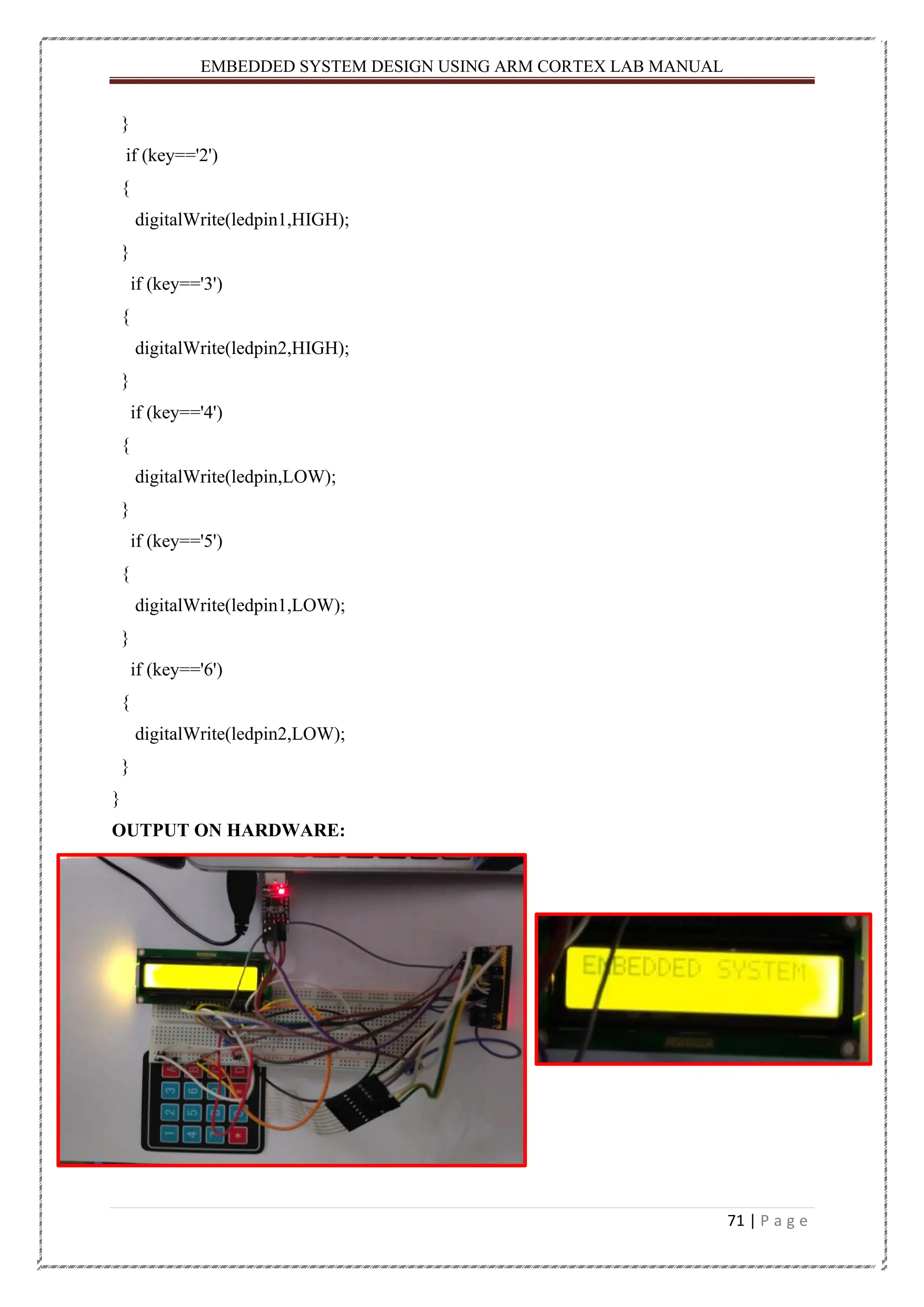
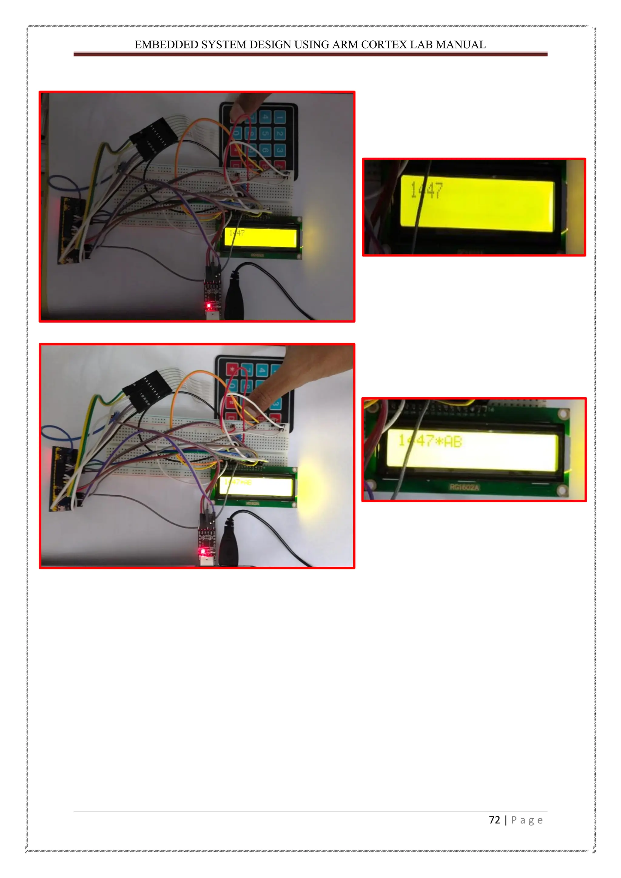
EMBEDDED SYSTEM DESIGNUSING ARM CORTEX LAB MANUAL 69 | P a g e CODE: Case-1: #include <Keypad.h> #include <LiquidCrystal.h> const byte ROWS = 4; //four rows const byte COLS = 4; //four columns //define the cymbols on the buttons of the keypads char hexaKeys[ROWS][COLS] = { {'1','2','3','A'}, {'4','5','6','B'}, {'7','8','9','C'}, {'*','0','#','D'} }; byte rowPins[ROWS] = {PA12, PA15, PB3, PB4}; //connect to the row pinouts of the keypad byte colPins[COLS] = {PB5, PB6, PB7, PB8}; //connect to the column pinouts of the keypad Keypad customKeypad = Keypad( makeKeymap(hexaKeys), rowPins, colPins, ROWS, COLS); LiquidCrystal lcd(PB11, PB10, PA0, PA1, PA2, PA3); void setup() { lcd.begin(16, 2); lcd.print("EMBEDDED SYSTEM"); delay(2000); lcd.clear(); lcd.setCursor(0, 0); } void loop() { char customKey = customKeypad.getKey(); if (customKey) { lcd.print(customKey); }}
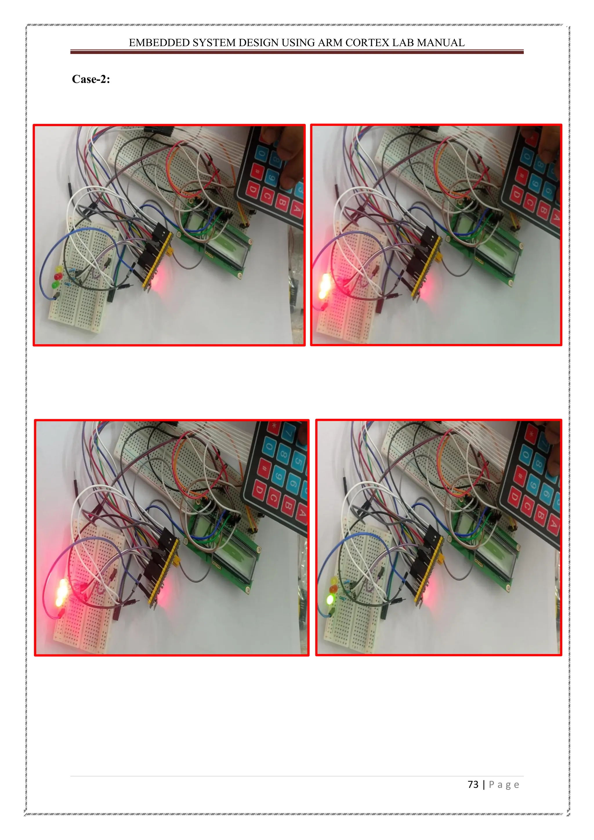
EMBEDDED SYSTEM DESIGNUSING ARM CORTEX LAB MANUAL 71 | P a g e } if (key=='2') { digitalWrite(ledpin1,HIGH); } if (key=='3') { digitalWrite(ledpin2,HIGH); } if (key=='4') { digitalWrite(ledpin,LOW); } if (key=='5') { digitalWrite(ledpin1,LOW); } if (key=='6') { digitalWrite(ledpin2,LOW); } } OUTPUT ON HARDWARE:
EMBEDDED SYSTEM DESIGNUSING ARM CORTEX LAB MANUAL 74 | P a g e CONCLUSION: From the above experiment I got to know about that how to interface with keypad STM32 board and learned about the pin configuration. Also, know that the interfacing of Keypad with LED. Teacher’s Remark : Date of Submission: 08.03.2022 Students Signature : Hitesh Kumar Nath Regd. No. : 200301150005 Teacher’s Signature : Branch : EEE
75.
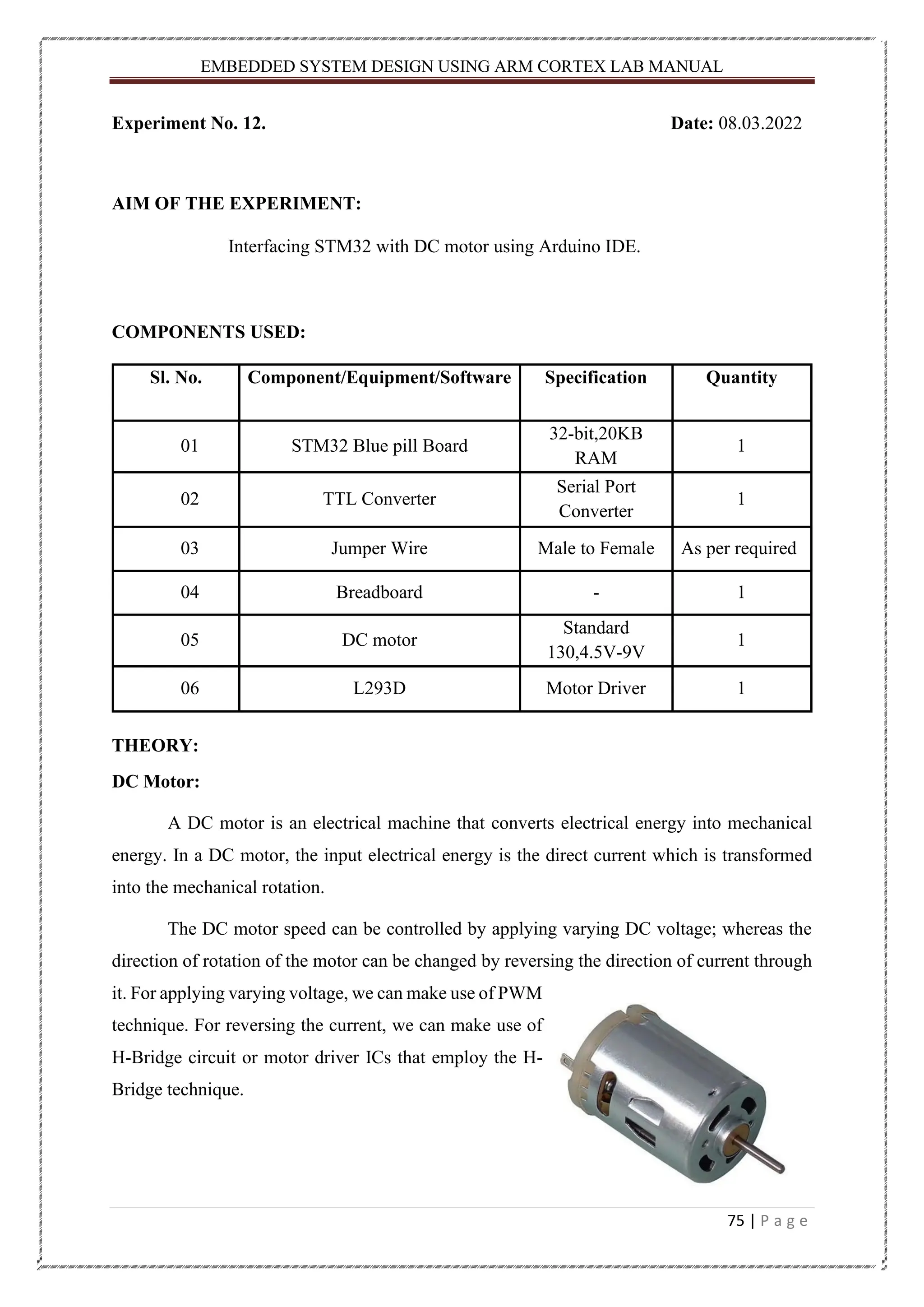
EMBEDDED SYSTEM DESIGNUSING ARM CORTEX LAB MANUAL 75 | P a g e Experiment No. 12. Date: 08.03.2022 AIM OF THE EXPERIMENT: Interfacing STM32 with DC motor using Arduino IDE. COMPONENTS USED: Sl. No. Component/Equipment/Software Specification Quantity 01 STM32 Blue pill Board 32-bit,20KB RAM 1 02 TTL Converter Serial Port Converter 1 03 Jumper Wire Male to Female As per required 04 Breadboard - 1 05 DC motor Standard 130,4.5V-9V 1 06 L293D Motor Driver 1 THEORY: DC Motor: A DC motor is an electrical machine that converts electrical energy into mechanical energy. In a DC motor, the input electrical energy is the direct current which is transformed into the mechanical rotation. The DC motor speed can be controlled by applying varying DC voltage; whereas the direction of rotation of the motor can be changed by reversing the direction of current through it. For applying varying voltage, we can make use of PWM technique. For reversing the current, we can make use of H-Bridge circuit or motor driver ICs that employ the H- Bridge technique.
76.
EMBEDDED SYSTEM DESIGNUSING ARM CORTEX LAB MANUAL 76 | P a g e L293D Motor Driver IC: A motor driver IC is an integrated circuit chip which is usually used to control motors in autonomous robots. The most commonly used motor driver IC’s are from the L293 series such as L293D, L293NE, etc. L293D consist of two H-bridge. H-bridge is the simplest circuit for controlling a low current rated motor. L293D has 16 pins, they are comprised as follows: Ground Pins - 4 Input Pins - 4 Output Pins - 4 Enable pins - 2 Voltage Pins - 2 Motor Driver IC L293D is running on the basic principle of H-Bridge, IC L293D has two-channel it consists of H-Bridge circuit in each channel therefore it’s known as Dual H- Bridge Motor Driver IC L293D. The circuit diagram of the H-Bridge is given below, the circuit diagram consists of four switches to control the direction of rotation of the motor. To understand the circuit diagram in a better way we will consider the following conditions. • When Switch S1 & S4 closed, a positive voltage is applied across the motor and it will rotate in a clockwise direction and when both switches are open, the motor will stop rotating. • When Switch S2 & S3 Closed, an inverting voltage is applied at the terminals of the motor and it will rotate in an anti-clockwise direction and when both switches are open, the motor will stop rotating. H-Bridge Circuit Diagram. • When Switches S1 & S3 are closed, the motor receives positive voltage at both terminals, forcing the motor to burn out due to excessive heat. • When Switches S2 & S4 are closed, the motor receives negative voltage at both terminals, forcing the motor to burn out due to excessive heat. • When Switches S1 & S2 are closed, the power supply gets shorted. • When Switches S3 & S4 are closed, the power supply gets shorted.
77.
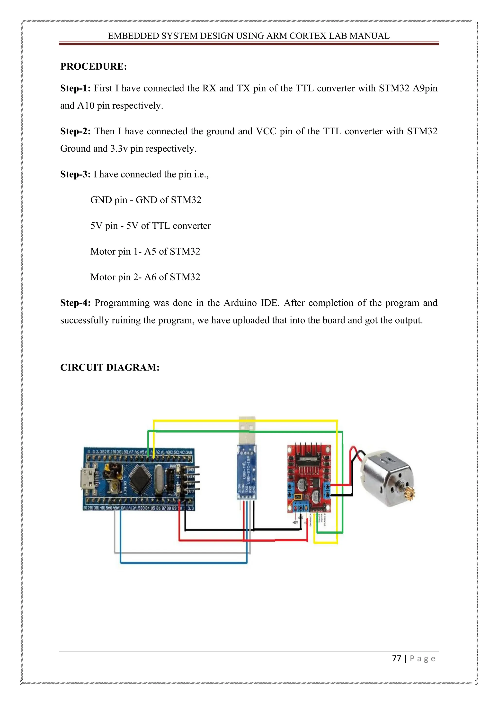
EMBEDDED SYSTEM DESIGNUSING ARM CORTEX LAB MANUAL 77 | P a g e PROCEDURE: Step-1: First I have connected the RX and TX pin of the TTL converter with STM32 A9pin and A10 pin respectively. Step-2: Then I have connected the ground and VCC pin of the TTL converter with STM32 Ground and 3.3v pin respectively. Step-3: I have connected the pin i.e., GND pin - GND of STM32 5V pin - 5V of TTL converter Motor pin 1- A5 of STM32 Motor pin 2- A6 of STM32 Step-4: Programming was done in the Arduino IDE. After completion of the program and successfully ruining the program, we have uploaded that into the board and got the output. CIRCUIT DIAGRAM:
78.
EMBEDDED SYSTEM DESIGNUSING ARM CORTEX LAB MANUAL 78 | P a g e CODE: const int direction1=PB3; const int direction2=PB4; { pinMode(direction1, OUTPUT); pinMode(direction2, OUTPUT); } void loop(){ digitalWrite(direction1,HIGH); digitalWrite(direction2, LOW); delay(10000); digitalWrite(direction1,LOW); digitalWrite(direction2, LOW); delay(1000); } OUTPUT ON HARDWARE:
79.
EMBEDDED SYSTEM DESIGNUSING ARM CORTEX LAB MANUAL 79 | P a g e CONCLUSION: From the above experiment, I got to know about that how to work with DC motor and also I learned that the interfacing of DC motor with STM32 board. Teacher’s Remark : Date of Submission: 09.03.2022 Students Signature : Hitesh Kumar Nath Regd. No. : 200301150005 Teacher’s Signature : Branch : EEE
80.
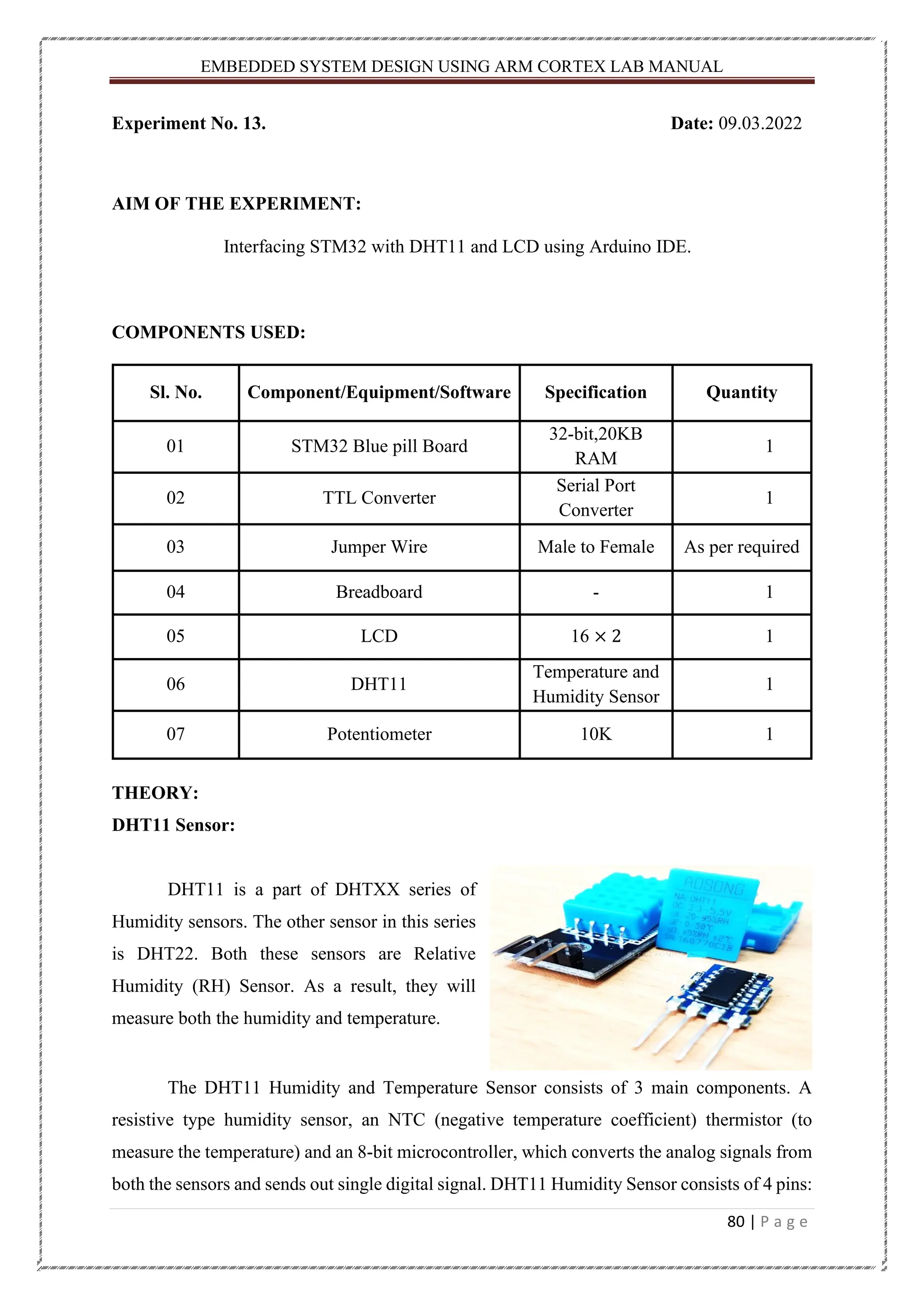
EMBEDDED SYSTEM DESIGNUSING ARM CORTEX LAB MANUAL 80 | P a g e Experiment No. 13. Date: 09.03.2022 AIM OF THE EXPERIMENT: Interfacing STM32 with DHT11 and LCD using Arduino IDE. COMPONENTS USED: Sl. No. Component/Equipment/Software Specification Quantity 01 STM32 Blue pill Board 32-bit,20KB RAM 1 02 TTL Converter Serial Port Converter 1 03 Jumper Wire Male to Female As per required 04 Breadboard - 1 05 LCD 16 × 2 1 06 DHT11 Temperature and Humidity Sensor 1 07 Potentiometer 10K 1 THEORY: DHT11 Sensor: DHT11 is a part of DHTXX series of Humidity sensors. The other sensor in this series is DHT22. Both these sensors are Relative Humidity (RH) Sensor. As a result, they will measure both the humidity and temperature. The DHT11 Humidity and Temperature Sensor consists of 3 main components. A resistive type humidity sensor, an NTC (negative temperature coefficient) thermistor (to measure the temperature) and an 8-bit microcontroller, which converts the analog signals from both the sensors and sends out single digital signal. DHT11 Humidity Sensor consists of 4 pins:
81.
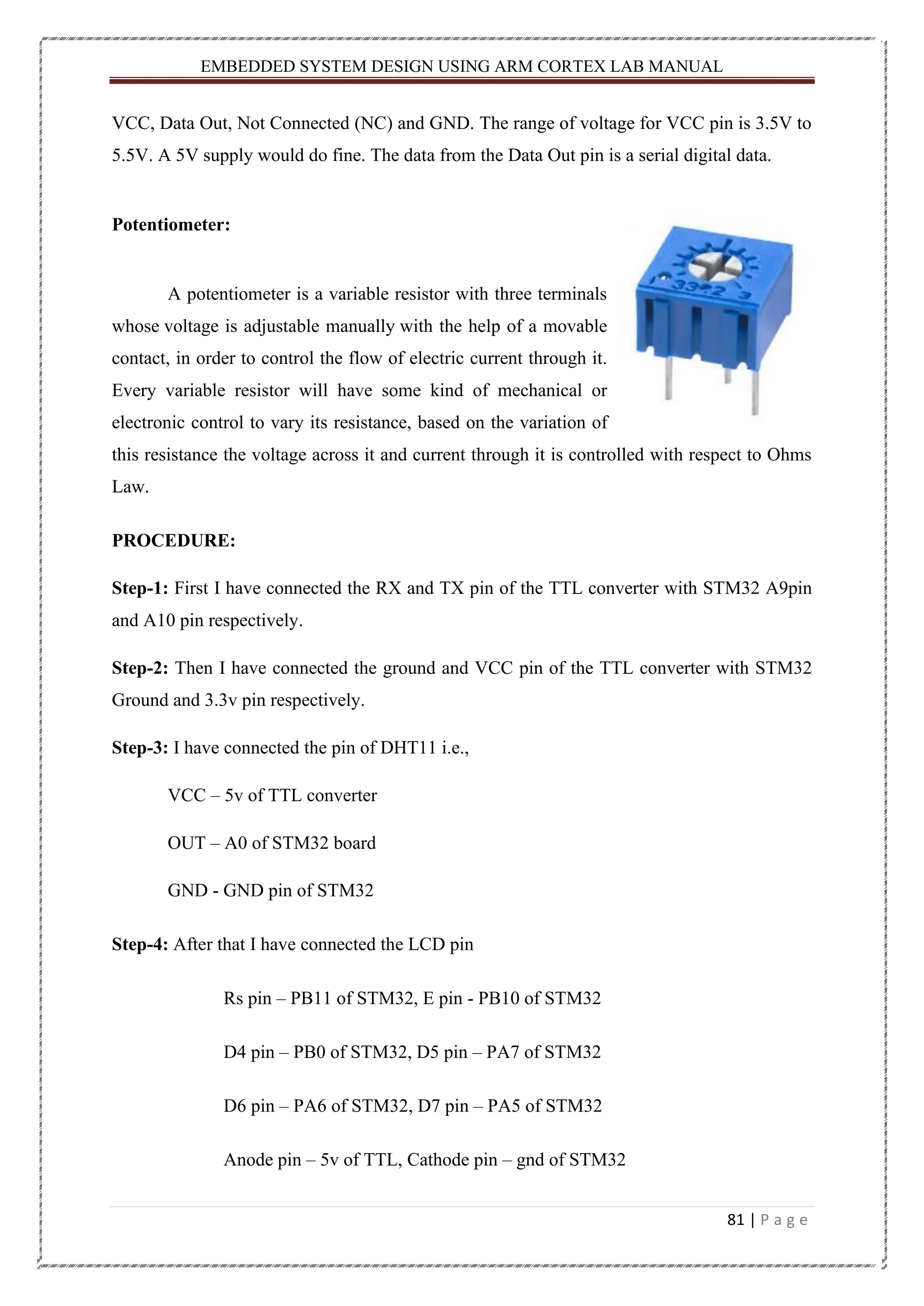
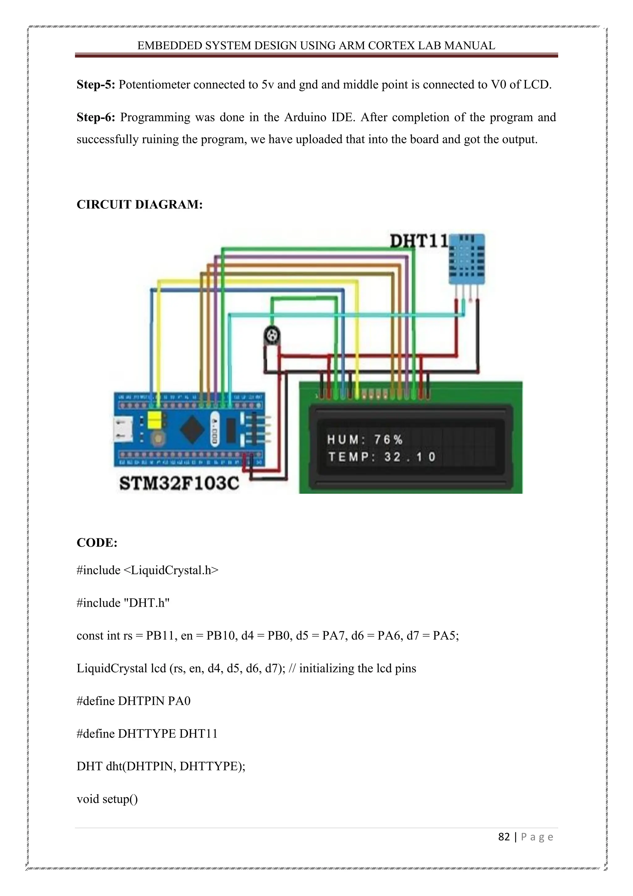
EMBEDDED SYSTEM DESIGNUSING ARM CORTEX LAB MANUAL 81 | P a g e VCC, Data Out, Not Connected (NC) and GND. The range of voltage for VCC pin is 3.5V to 5.5V. A 5V supply would do fine. The data from the Data Out pin is a serial digital data. Potentiometer: A potentiometer is a variable resistor with three terminals whose voltage is adjustable manually with the help of a movable contact, in order to control the flow of electric current through it. Every variable resistor will have some kind of mechanical or electronic control to vary its resistance, based on the variation of this resistance the voltage across it and current through it is controlled with respect to Ohms Law. PROCEDURE: Step-1: First I have connected the RX and TX pin of the TTL converter with STM32 A9pin and A10 pin respectively. Step-2: Then I have connected the ground and VCC pin of the TTL converter with STM32 Ground and 3.3v pin respectively. Step-3: I have connected the pin of DHT11 i.e., VCC – 5v of TTL converter OUT – A0 of STM32 board GND - GND pin of STM32 Step-4: After that I have connected the LCD pin Rs pin – PB11 of STM32, E pin - PB10 of STM32 D4 pin – PB0 of STM32, D5 pin – PA7 of STM32 D6 pin – PA6 of STM32, D7 pin – PA5 of STM32 Anode pin – 5v of TTL, Cathode pin – gnd of STM32
82.
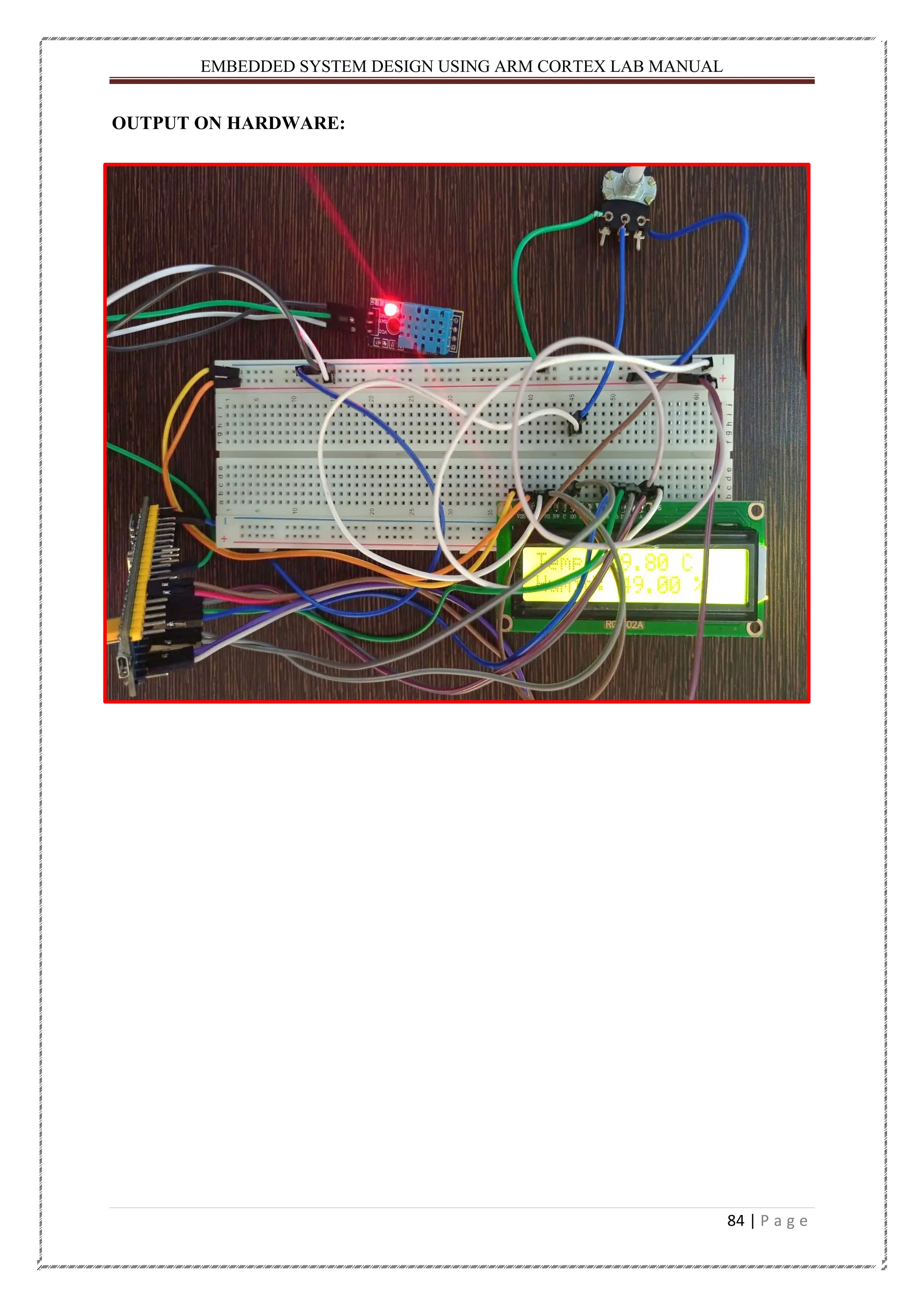
EMBEDDED SYSTEM DESIGNUSING ARM CORTEX LAB MANUAL 82 | P a g e Step-5: Potentiometer connected to 5v and gnd and middle point is connected to V0 of LCD. Step-6: Programming was done in the Arduino IDE. After completion of the program and successfully ruining the program, we have uploaded that into the board and got the output. CIRCUIT DIAGRAM: CODE: #include <LiquidCrystal.h> #include "DHT.h" const int rs = PB11, en = PB10, d4 = PB0, d5 = PA7, d6 = PA6, d7 = PA5; LiquidCrystal lcd (rs, en, d4, d5, d6, d7); // initializing the lcd pins #define DHTPIN PA0 #define DHTTYPE DHT11 DHT dht(DHTPIN, DHTTYPE); void setup()
83.
EMBEDDED SYSTEM DESIGNUSING ARM CORTEX LAB MANUAL 83 | P a g e { dht.begin(); lcd.begin(16, 2); lcd.setCursor(0, 0); lcd.print("DHT11 with STM32"); delay(3000); lcd.clear(); } void loop() { float h = dht.readHumidity(); //Gets Humidity value float t = dht.readTemperature(); //Gets Temperature value lcd.setCursor(0, 0); lcd.print("Temp: "); lcd.print(t); lcd.print(" C"); lcd.setCursor(0, 1); lcd.print("Humid: "); lcd.print(h); lcd.print(" %"); }
EMBEDDED SYSTEM DESIGNUSING ARM CORTEX LAB MANUAL 85 | P a g e CONCLUSION: From the above experiment, I got to know that how to work with DHT11 and learned that how to interface with STM32 board. Teacher’s Remark : Date of Submission: 10.03.2022 Students Signature : Hitesh Kumar Nath Regd. No. : 200301150005 Teacher’s Signature : Branch : EEE
86.
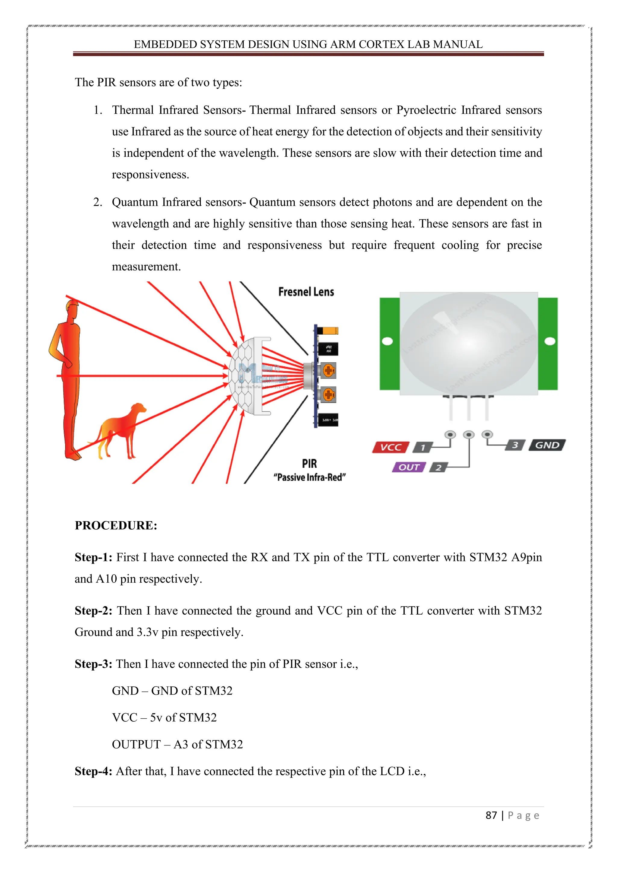
EMBEDDED SYSTEM DESIGNUSING ARM CORTEX LAB MANUAL 86 | P a g e Experiment No. 14. Date: 10.03.2022 AIM OF THE EXPERIMENT: Interfacing STM32 with PIR sensor using Arduino IDE. COMPONENTS USED: Sl. No. Component/Equipment/Software Specification Quantity 01 STM32 Blue pill Board 32-bit,20KB RAM 1 02 TTL Converter Serial Port Converter 1 03 Jumper Wire Male to Female As per required 04 Breadboard - 1 05 LCD 16 × 2 1 06 PIR 4.8V-20V 1 07 Potentiometer 10K 1 THEORY: PIR Sensor: A passive infrared (PIR) sensor recognizes infrared light emitted from nearby objects. PIR sensors are used in thermal sensing applications, such as security and motion detection. They are commonly used in security alarms, motion detection alarms, and automatic lighting applications. Passive infrared (PIR) sensors use a pair of pyroelectric sensors to detect heat energy in the surrounding environment. These two sensors sit beside each other, and when the signal differential between the two sensors changes (if a person enters the room, for example), the sensor will engage.
87.
EMBEDDED SYSTEM DESIGNUSING ARM CORTEX LAB MANUAL 87 | P a g e The PIR sensors are of two types: 1. Thermal Infrared Sensors- Thermal Infrared sensors or Pyroelectric Infrared sensors use Infrared as the source of heat energy for the detection of objects and their sensitivity is independent of the wavelength. These sensors are slow with their detection time and responsiveness. 2. Quantum Infrared sensors- Quantum sensors detect photons and are dependent on the wavelength and are highly sensitive than those sensing heat. These sensors are fast in their detection time and responsiveness but require frequent cooling for precise measurement. PROCEDURE: Step-1: First I have connected the RX and TX pin of the TTL converter with STM32 A9pin and A10 pin respectively. Step-2: Then I have connected the ground and VCC pin of the TTL converter with STM32 Ground and 3.3v pin respectively. Step-3: Then I have connected the pin of PIR sensor i.e., GND – GND of STM32 VCC – 5v of STM32 OUTPUT – A3 of STM32 Step-4: After that, I have connected the respective pin of the LCD i.e.,
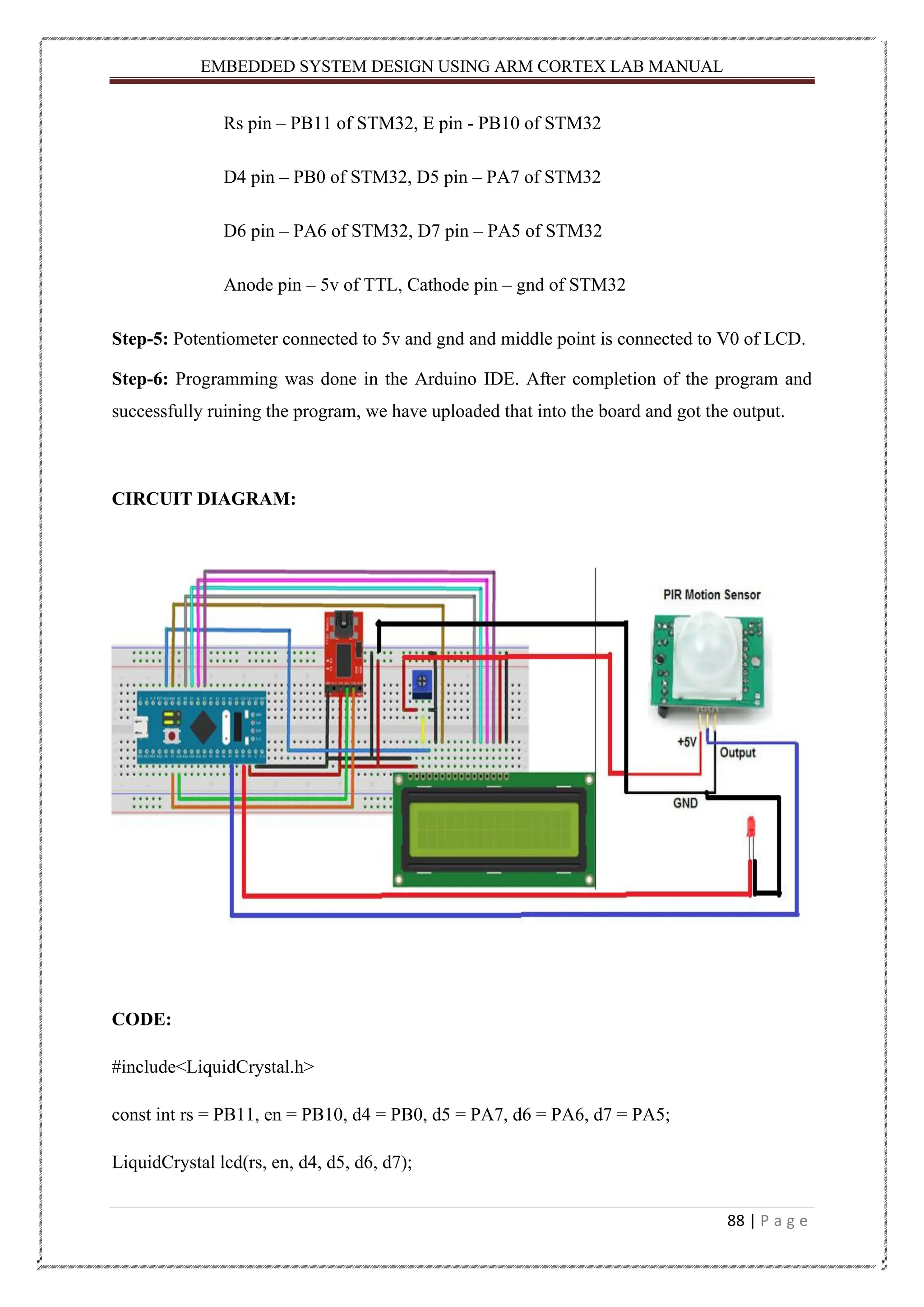
88.
EMBEDDED SYSTEM DESIGNUSING ARM CORTEX LAB MANUAL 88 | P a g e Rs pin – PB11 of STM32, E pin - PB10 of STM32 D4 pin – PB0 of STM32, D5 pin – PA7 of STM32 D6 pin – PA6 of STM32, D7 pin – PA5 of STM32 Anode pin – 5v of TTL, Cathode pin – gnd of STM32 Step-5: Potentiometer connected to 5v and gnd and middle point is connected to V0 of LCD. Step-6: Programming was done in the Arduino IDE. After completion of the program and successfully ruining the program, we have uploaded that into the board and got the output. CIRCUIT DIAGRAM: CODE: #include<LiquidCrystal.h> const int rs = PB11, en = PB10, d4 = PB0, d5 = PA7, d6 = PA6, d7 = PA5; LiquidCrystal lcd(rs, en, d4, d5, d6, d7);
89.
EMBEDDED SYSTEM DESIGNUSING ARM CORTEX LAB MANUAL 89 | P a g e int calibrationTime = 10; long unsigned int lowIn; long unsigned int pause = 5000; boolean lockLow = true; boolean takeLowTime; int pirPin = PA0; int pinBuzzer =PB5; void setup(){ lcd.begin(16,2); pinMode(pirPin, INPUT); pinMode(pinBuzzer, OUTPUT); digitalWrite(pirPin, LOW); lcd.print("calibrtng "); delay(1000); lcd.clear(); for(int i = 1; i < calibrationTime; i++){ lcd.print(i); delay(1000); lcd.clear(); } lcd.clear(); lcd.setCursor(0,0); lcd.print("DEVICE");
90.
EMBEDDED SYSTEM DESIGNUSING ARM CORTEX LAB MANUAL 90 | P a g e lcd.setCursor(0,1); lcd.print("ACTIVE"); delay(1000); lcd.clear(); } void loop(){ if(digitalRead(pirPin) == HIGH){ digitalWrite(pinBuzzer, HIGH); if(lockLow){ lockLow = false; lcd.setCursor(0,0); lcd.print("START "); lcd.print(millis()/1000); lcd.print(" sec"); delay(50); } takeLowTime = true; } if(digitalRead(pirPin) == LOW){ digitalWrite(pinBuzzer, LOW); if(takeLowTime){ lowIn = millis(); takeLowTime = false;
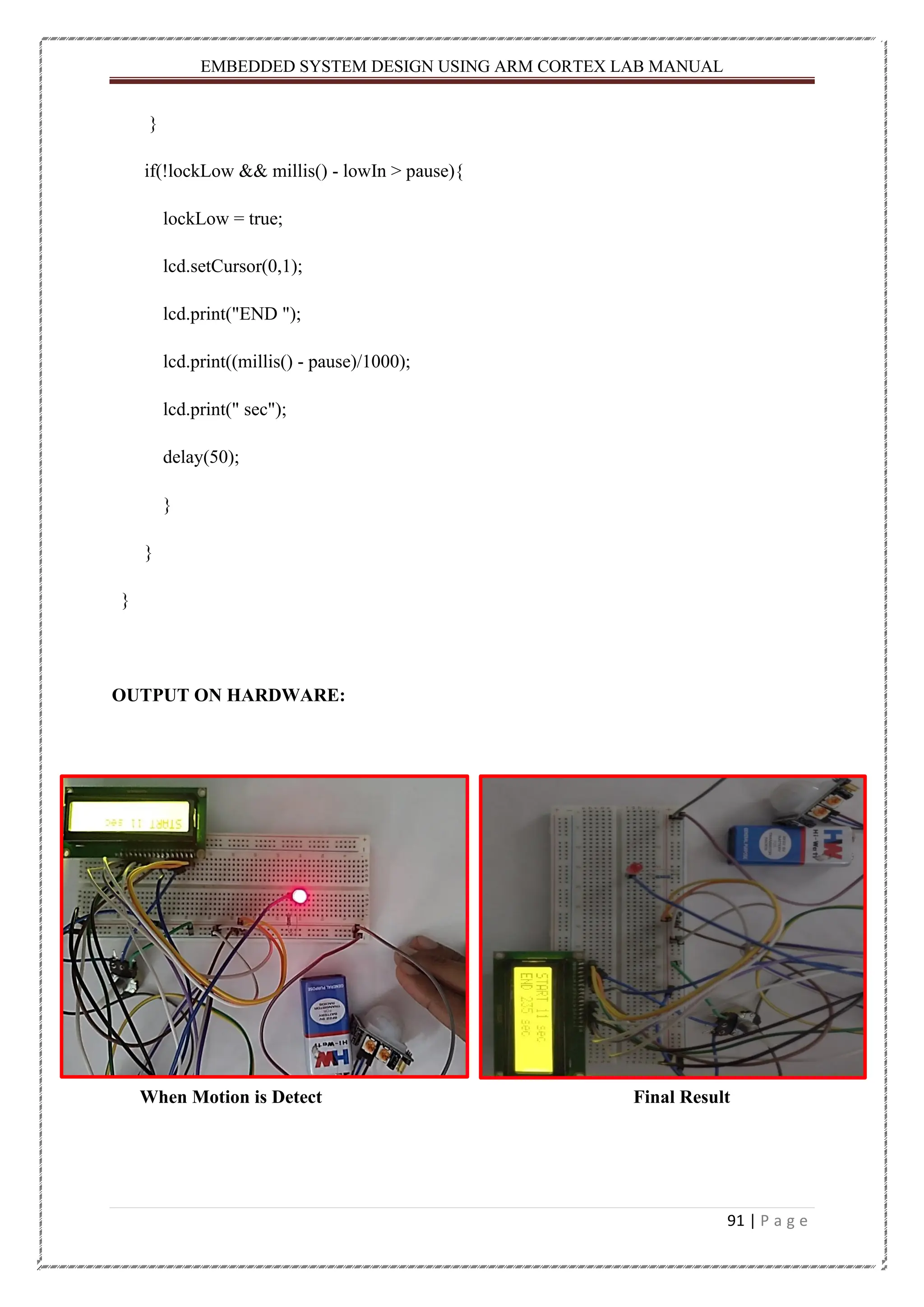
91.
EMBEDDED SYSTEM DESIGNUSING ARM CORTEX LAB MANUAL 91 | P a g e } if(!lockLow && millis() - lowIn > pause){ lockLow = true; lcd.setCursor(0,1); lcd.print("END "); lcd.print((millis() - pause)/1000); lcd.print(" sec"); delay(50); } } } OUTPUT ON HARDWARE: When Motion is Detect Final Result
92.
EMBEDDED SYSTEM DESIGNUSING ARM CORTEX LAB MANUAL 92 | P a g e CONCLUSION: After completed this experiment, I got know about the PIR sensor and it’s pin out and also learned that how to interface with STM32 board. Teacher’s Remark : Date of Submission: 15.03.2022 Students Signature : Hitesh Kumar Nath Regd. No. : 200301150005 Teacher’s Signature : Branch : EEE
93.
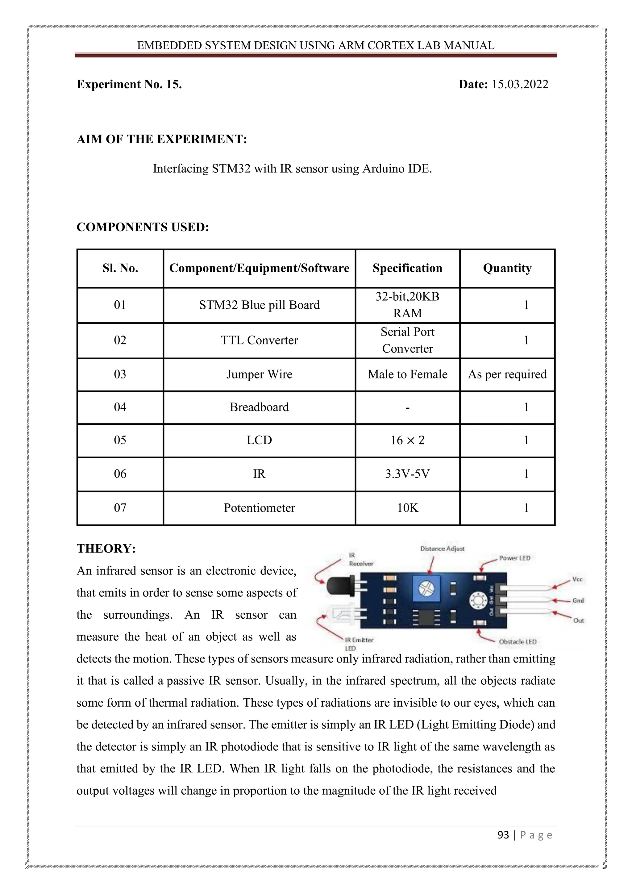
EMBEDDED SYSTEM DESIGNUSING ARM CORTEX LAB MANUAL 93 | P a g e Experiment No. 15. Date: 15.03.2022 AIM OF THE EXPERIMENT: Interfacing STM32 with IR sensor using Arduino IDE. COMPONENTS USED: Sl. No. Component/Equipment/Software Specification Quantity 01 STM32 Blue pill Board 32-bit,20KB RAM 1 02 TTL Converter Serial Port Converter 1 03 Jumper Wire Male to Female As per required 04 Breadboard - 1 05 LCD 16 × 2 1 06 IR 3.3V-5V 1 07 Potentiometer 10K 1 THEORY: An infrared sensor is an electronic device, that emits in order to sense some aspects of the surroundings. An IR sensor can measure the heat of an object as well as detects the motion. These types of sensors measure only infrared radiation, rather than emitting it that is called a passive IR sensor. Usually, in the infrared spectrum, all the objects radiate some form of thermal radiation. These types of radiations are invisible to our eyes, which can be detected by an infrared sensor. The emitter is simply an IR LED (Light Emitting Diode) and the detector is simply an IR photodiode that is sensitive to IR light of the same wavelength as that emitted by the IR LED. When IR light falls on the photodiode, the resistances and the output voltages will change in proportion to the magnitude of the IR light received
94.
EMBEDDED SYSTEM DESIGNUSING ARM CORTEX LAB MANUAL 94 | P a g e IR sensors are classified into different types depending on the applications. Some of the typical applications of different types of sensors. The speed sensor is used for synchronizing the speed of multiple motors. The temperature sensor is used for industrial temperature control. PIR sensor is used for an automatic door opening system and the Ultrasonic sensor is used for distance measurement. Active IR Sensor: This active infrared sensor includes both the transmitter as well as the receiver. In most of the applications, the light-emitting diode is used as a source. LED is used as a non-imaging infrared sensor whereas the laser diode is used as an imaging infrared sensor. Passive IR Sensor: The passive infrared sensor includes detectors only but they don’t include a transmitter. These sensors use an object like a transmitter or IR source. This object emits energy and detects through infrared receivers. After that, a signal processor is used to understand the signal to obtain the required information. PROCEDURE: Step-1: First I have connected the RX and TX pin of the TTL converter with STM32 A9pin and A10 pin respectively. Step-2: Then I have connected the ground and VCC pin of the TTL converter with STM32 Ground and 3.3v pin respectively. Step-3: After that, I have connected the respective pin of the LCD i.e., Rs pin – PB11 of STM32, E pin - PB10 of STM32 D4 pin –PB0 of STM32, D5 pin –PA7 of STM32 D6 pin –PA6 of STM32, D7 pin –PA5 of STM32 Anode pin – 5v of TTL, Cathode pin – gnd of STM32 Step-4: Potentiometer connected to 5v and gnd and middle point is connected to V0 of LCD.
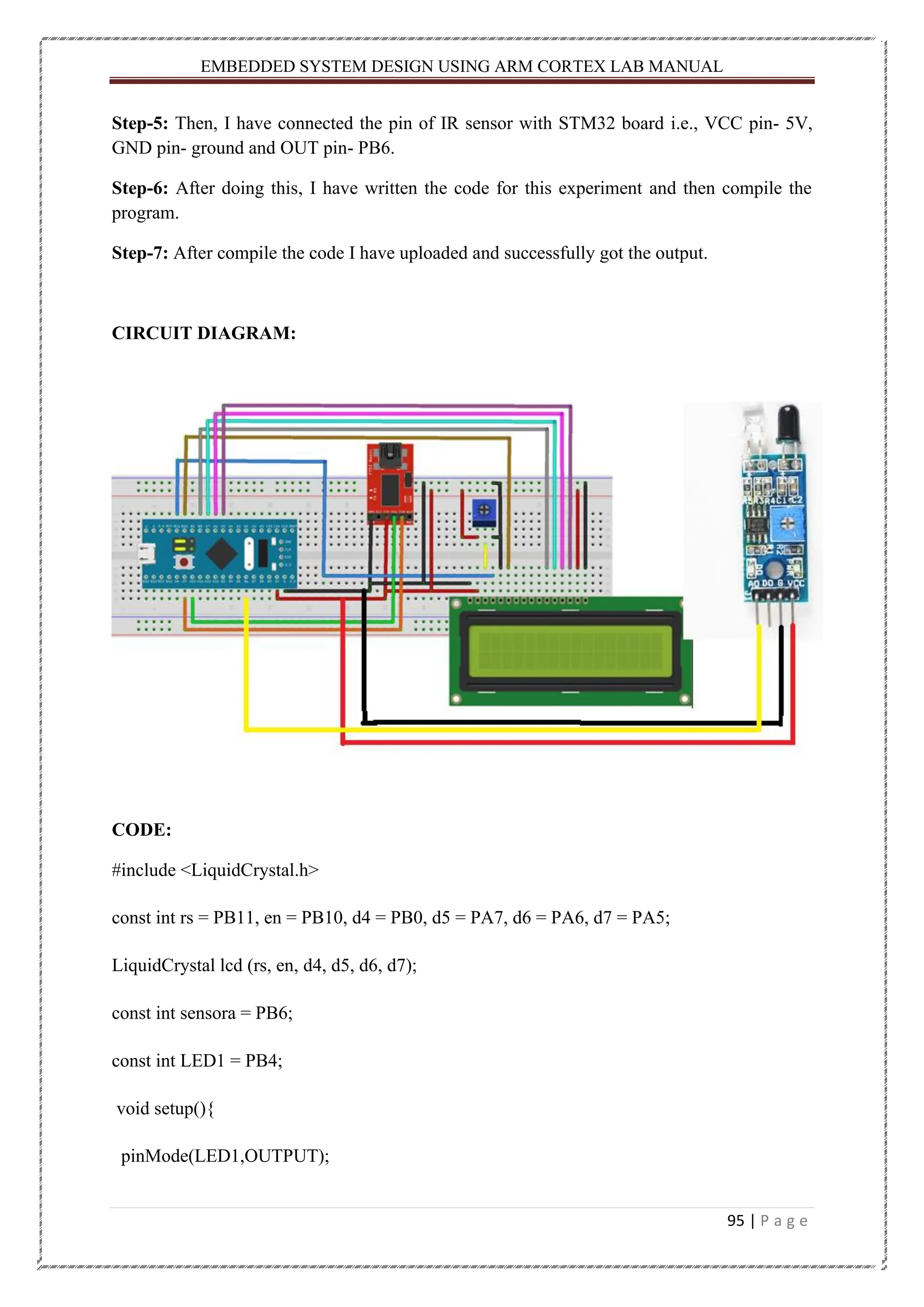
95.
EMBEDDED SYSTEM DESIGNUSING ARM CORTEX LAB MANUAL 95 | P a g e Step-5: Then, I have connected the pin of IR sensor with STM32 board i.e., VCC pin- 5V, GND pin- ground and OUT pin- PB6. Step-6: After doing this, I have written the code for this experiment and then compile the program. Step-7: After compile the code I have uploaded and successfully got the output. CIRCUIT DIAGRAM: CODE: #include <LiquidCrystal.h> const int rs = PB11, en = PB10, d4 = PB0, d5 = PA7, d6 = PA6, d7 = PA5; LiquidCrystal lcd (rs, en, d4, d5, d6, d7); const int sensora = PB6; const int LED1 = PB4; void setup(){ pinMode(LED1,OUTPUT);
96.
EMBEDDED SYSTEM DESIGNUSING ARM CORTEX LAB MANUAL 96 | P a g e lcd.clear(); lcd.begin(16,2); lcd.setCursor(3,0); lcd.print("IR Sesnsor"); lcd.setCursor(0,1); lcd.print("Embedded System"); delay(500); } void loop(){ Sensor1(); delay(500); } void Sensor1(){ int statusSensor1 = digitalRead (sensora); if (statusSensor1 == 1){ digitalWrite(LED1, LOW); lcd.setCursor(0,0); lcd.print("Object Is Not Found"); lcd.setCursor(1,1); lcd.print(" The LED IS OFF "); } else {
97.
EMBEDDED SYSTEM DESIGNUSING ARM CORTEX LAB MANUAL 97 | P a g e digitalWrite(LED1, HIGH); lcd.setCursor(0,0); lcd.print("Object is Found"); lcd.setCursor(0,1); lcd.print(" The LED IS ON "); } } OUTPUT ON HARDWARE: (Initial State) (Final State)
98.
EMBEDDED SYSTEM DESIGNUSING ARM CORTEX LAB MANUAL 98 | P a g e CONCLUSION: After doing this experiment, I got to know about that how to work with IR sensor and done the interfacing with STM32 board. Teacher’s Remark : Date of Submission: 16.03.2022 Students Signature : Hitesh Kumar Nath Regd. No. : 200301150005 Teacher’s Signature : Branch : EEE
99.
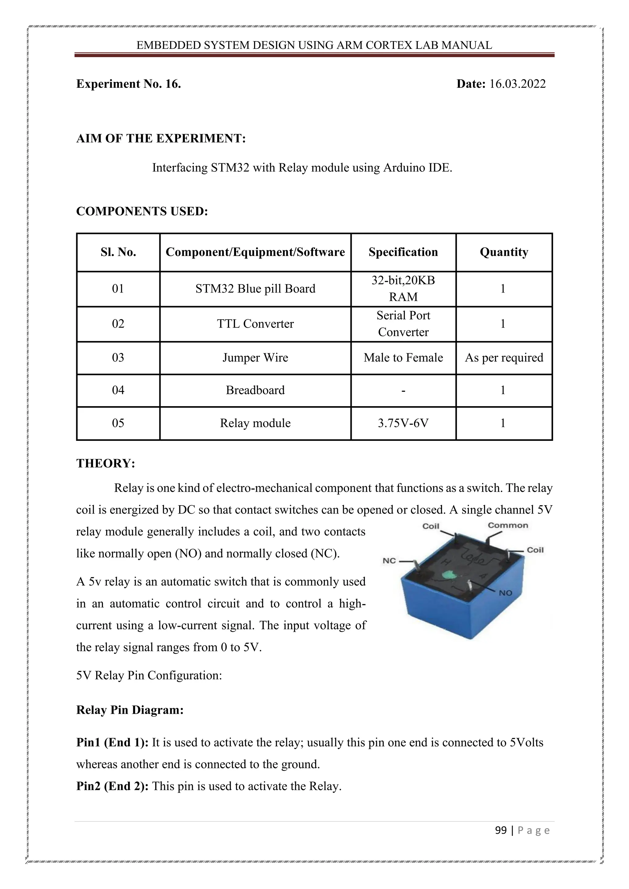
EMBEDDED SYSTEM DESIGNUSING ARM CORTEX LAB MANUAL 99 | P a g e Experiment No. 16. Date: 16.03.2022 AIM OF THE EXPERIMENT: Interfacing STM32 with Relay module using Arduino IDE. COMPONENTS USED: Sl. No. Component/Equipment/Software Specification Quantity 01 STM32 Blue pill Board 32-bit,20KB RAM 1 02 TTL Converter Serial Port Converter 1 03 Jumper Wire Male to Female As per required 04 Breadboard - 1 05 Relay module 3.75V-6V 1 THEORY: Relay is one kind of electro-mechanical component that functions as a switch. The relay coil is energized by DC so that contact switches can be opened or closed. A single channel 5V relay module generally includes a coil, and two contacts like normally open (NO) and normally closed (NC). A 5v relay is an automatic switch that is commonly used in an automatic control circuit and to control a high- current using a low-current signal. The input voltage of the relay signal ranges from 0 to 5V. 5V Relay Pin Configuration: Relay Pin Diagram: Pin1 (End 1): It is used to activate the relay; usually this pin one end is connected to 5Volts whereas another end is connected to the ground. Pin2 (End 2): This pin is used to activate the Relay.
100.
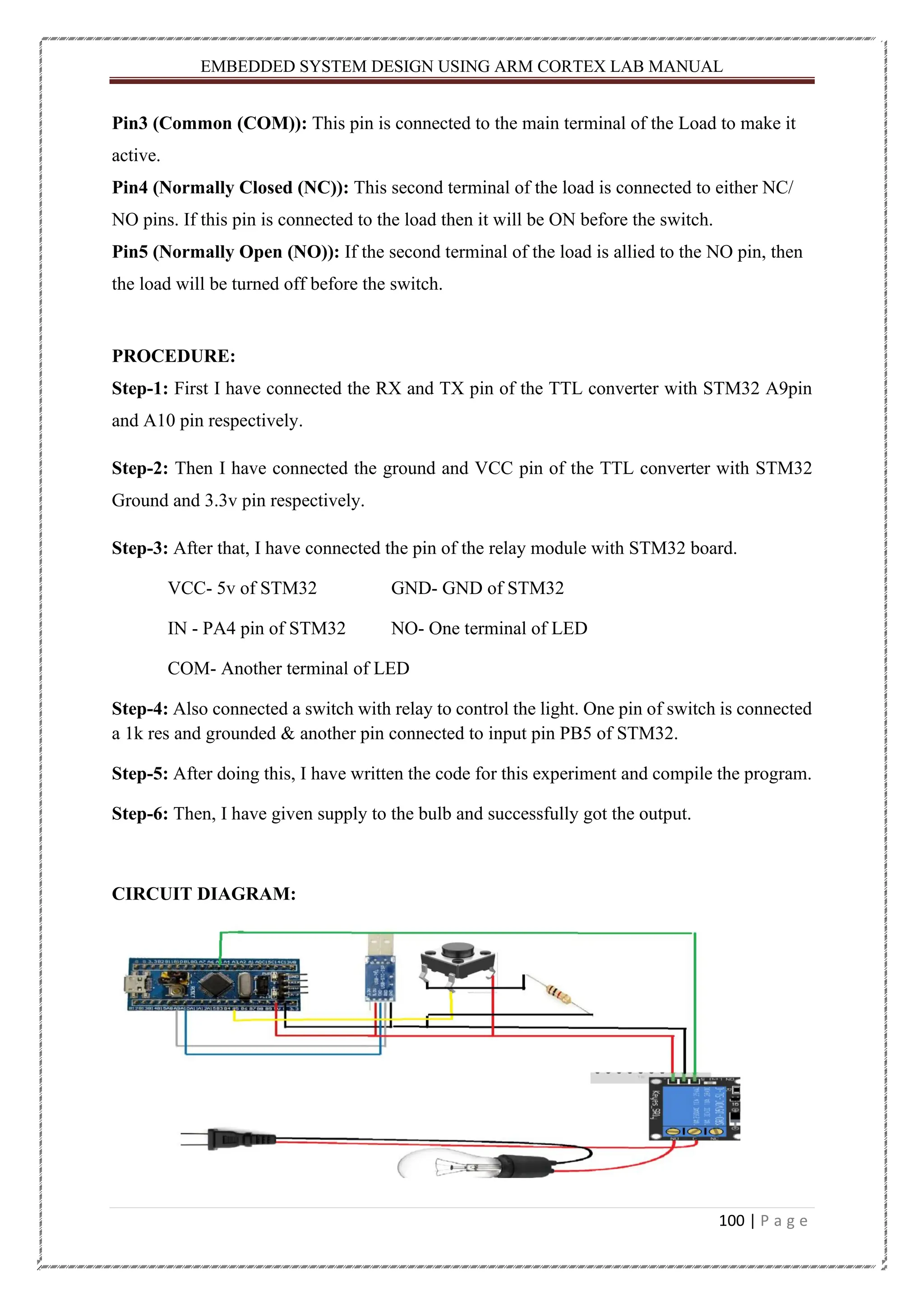
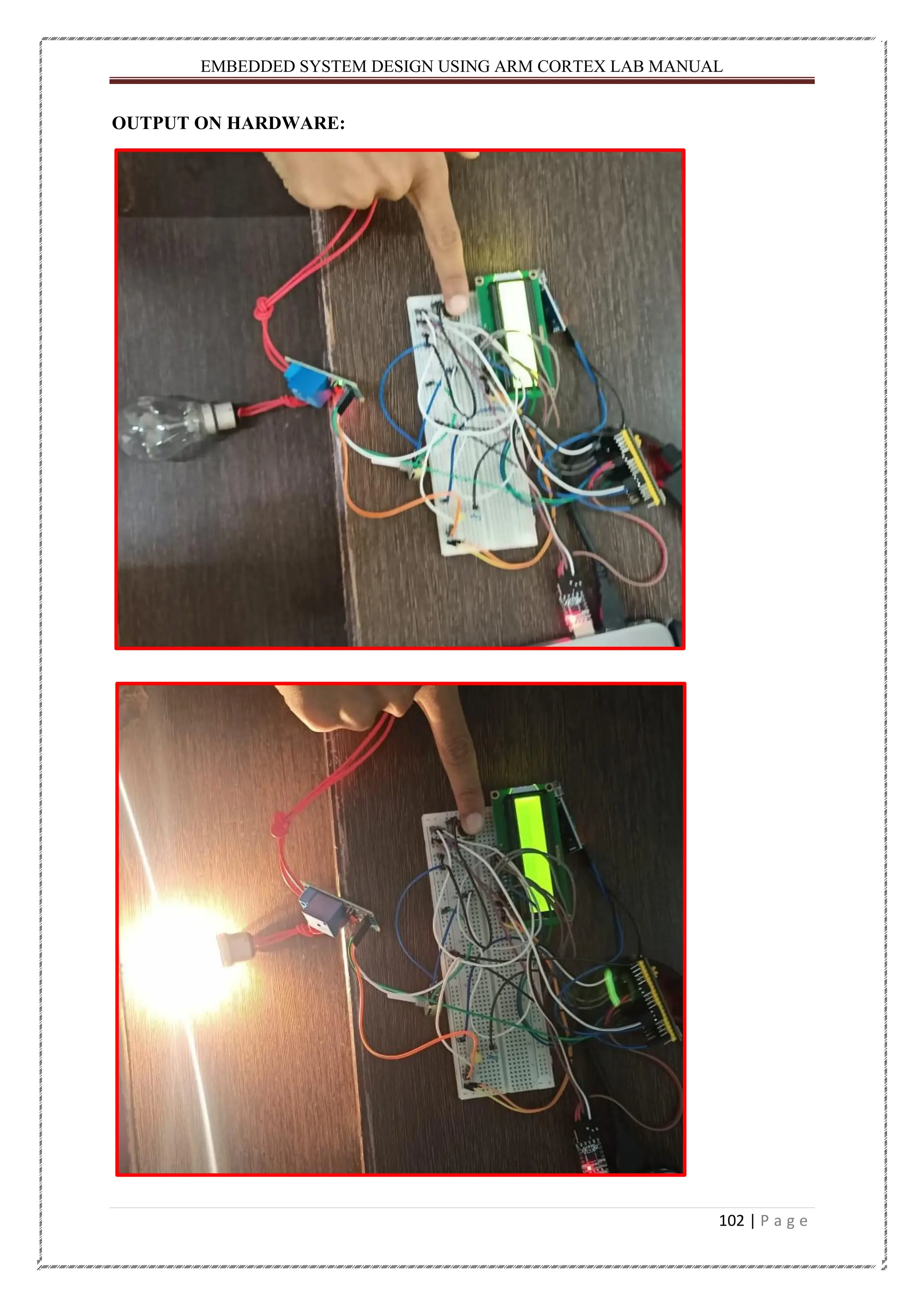
EMBEDDED SYSTEM DESIGNUSING ARM CORTEX LAB MANUAL 100 | P a g e Pin3 (Common (COM)): This pin is connected to the main terminal of the Load to make it active. Pin4 (Normally Closed (NC)): This second terminal of the load is connected to either NC/ NO pins. If this pin is connected to the load then it will be ON before the switch. Pin5 (Normally Open (NO)): If the second terminal of the load is allied to the NO pin, then the load will be turned off before the switch. PROCEDURE: Step-1: First I have connected the RX and TX pin of the TTL converter with STM32 A9pin and A10 pin respectively. Step-2: Then I have connected the ground and VCC pin of the TTL converter with STM32 Ground and 3.3v pin respectively. Step-3: After that, I have connected the pin of the relay module with STM32 board. VCC- 5v of STM32 GND- GND of STM32 IN - PA4 pin of STM32 NO- One terminal of LED COM- Another terminal of LED Step-4: Also connected a switch with relay to control the light. One pin of switch is connected a 1k res and grounded & another pin connected to input pin PB5 of STM32. Step-5: After doing this, I have written the code for this experiment and compile the program. Step-6: Then, I have given supply to the bulb and successfully got the output. CIRCUIT DIAGRAM:
101.
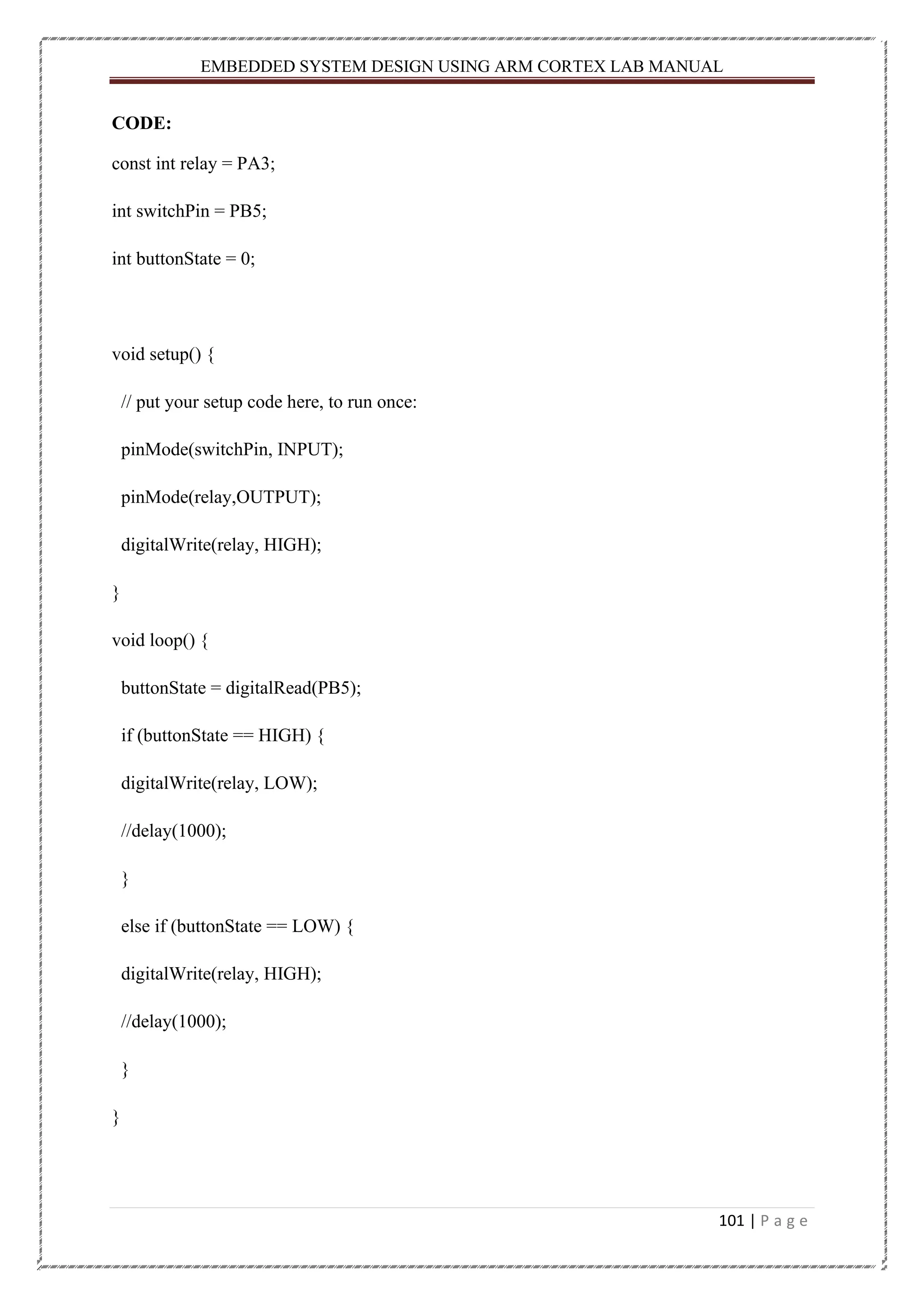
EMBEDDED SYSTEM DESIGNUSING ARM CORTEX LAB MANUAL 101 | P a g e CODE: const int relay = PA3; int switchPin = PB5; int buttonState = 0; void setup() { // put your setup code here, to run once: pinMode(switchPin, INPUT); pinMode(relay,OUTPUT); digitalWrite(relay, HIGH); } void loop() { buttonState = digitalRead(PB5); if (buttonState == HIGH) { digitalWrite(relay, LOW); //delay(1000); } else if (buttonState == LOW) { digitalWrite(relay, HIGH); //delay(1000); } }
EMBEDDED SYSTEM DESIGNUSING ARM CORTEX LAB MANUAL 103 | P a g e CONCLUSION: After completed this experiment, I got know about the relay module and how to interface with STM32 board. Teacher’s Remark : Date of Submission: 17.03.2022 Students Signature : Hitesh Kumar Nath Regd. No. : 200301150005 Teacher’s Signature : Branch : EEE
104.
EMBEDDED SYSTEM DESIGNUSING ARM CORTEX LAB MANUAL 104 | P a g e Experiment No. 17. Date: 17.03.2022 AIM OF THE EXPERIMENT: Interfacing STM32 with Servo motor using Arduino IDE. COMPONENTS USED: Sl. No. Component/Equipment/Software Specification Quantity 01 STM32 Blue pill Board 32-bit,20KB RAM 1 02 TTL Converter Serial Port Converter 1 03 Jumper Wire Male to Female As per required 04 Breadboard - 1 05 Servo Motor 5V 1 06 Potentiometer 10K 1 THEORY: Servo Meter: A servo motor is a type of motor that can rotate with great precision. Normally this type of motor consists of a control circuit that provides feedback on the current position of the motor shaft, this feedback allows the servo motors to rotate with great precision. If you want to rotate an object at some specific angles or distance, then you use a servo motor. It is just made up of a simple motor which runs through a servo mechanism. If motor is powered by a DC power supply then it is called DC servo motor, and if it is AC-powered motor then it is called AC servo motor. For this tutorial, we will be discussing only about the DC servo motor working. Apart from these major classifications, there are many other types of servo motors based on the type of gear arrangement and operating characteristics. A servo motor usually comes with a gear arrangement that allows us to get a very high torque servo motor in small
105.
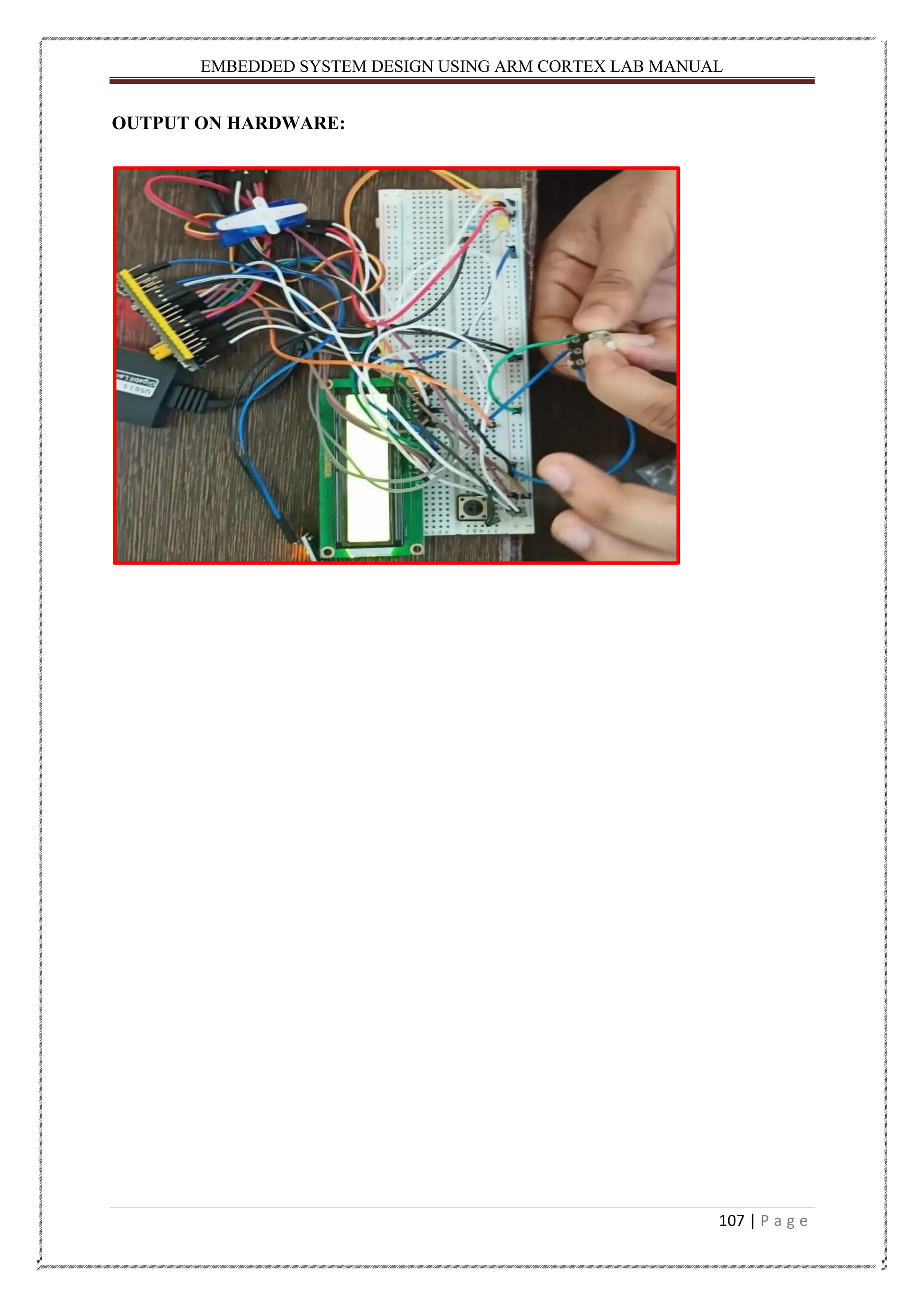
EMBEDDED SYSTEM DESIGNUSING ARM CORTEX LAB MANUAL 105 | P a g e and lightweight packages. Due to these features, they are being used in many applications like toy car, RC helicopters and planes, Robotics, etc. It consists of three parts: 1. Controlled device 2. Output sensor 3. Feedback system It is a closed-loop system where it uses a positive feedback system to control motion and the final position of the shaft. Here the device is controlled by a feedback signal generated by comparing output signal and reference input signal. PROCEDURE: Step-1: First I have connected the RX and TX pin of the TTL converter with STM32 A9pin and A10 pin respectively. Step-2: Then I have connected the ground and VCC pin of the TTL converter with STM32 Ground and 3.3v pin respectively. Step-3: Then, I have connected the pin of Servo motor i.e., VCC – 5v of STM32 GND – GND of STM32 IN - PA5 of STM32 Step-4: Connected a potentiometer to control the direction of the motor. Step-5: After doing this, I have written the code for this experiment and then compile the program. Step-6: After compile the code I have uploaded and successfully got the output.
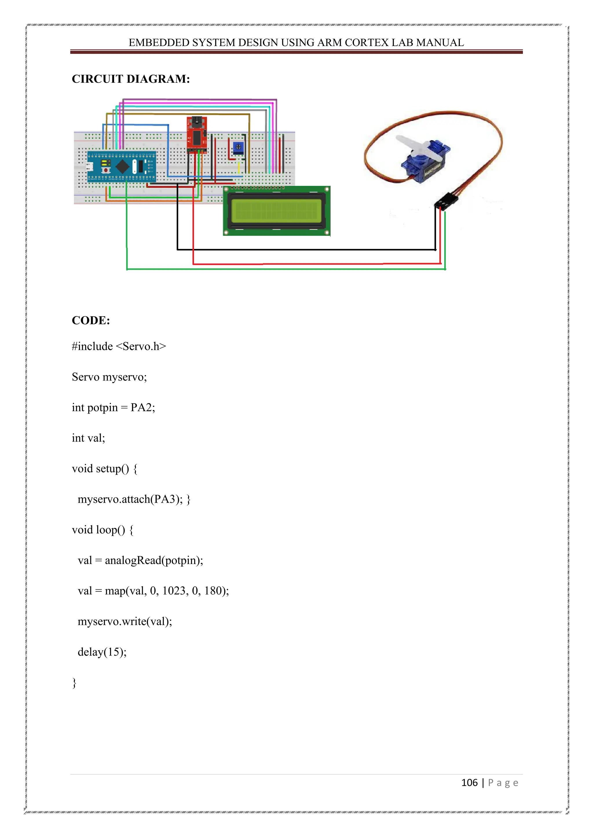
106.
EMBEDDED SYSTEM DESIGNUSING ARM CORTEX LAB MANUAL 106 | P a g e CIRCUIT DIAGRAM: CODE: #include <Servo.h> Servo myservo; int potpin = PA2; int val; void setup() { myservo.attach(PA3); } void loop() { val = analogRead(potpin); val = map(val, 0, 1023, 0, 180); myservo.write(val); delay(15); }
EMBEDDED SYSTEM DESIGNUSING ARM CORTEX LAB MANUAL 108 | P a g e CONCLUSION: After completed this experiment, I got know about the servo motor and how to interface with STM32 board. Teacher’s Remark : Date of Submission: 22.03.2022 Students Signature : Hitesh Kumar Nath Regd. No. : 200301150005 Teacher’s Signature : Branch : EEE
109.
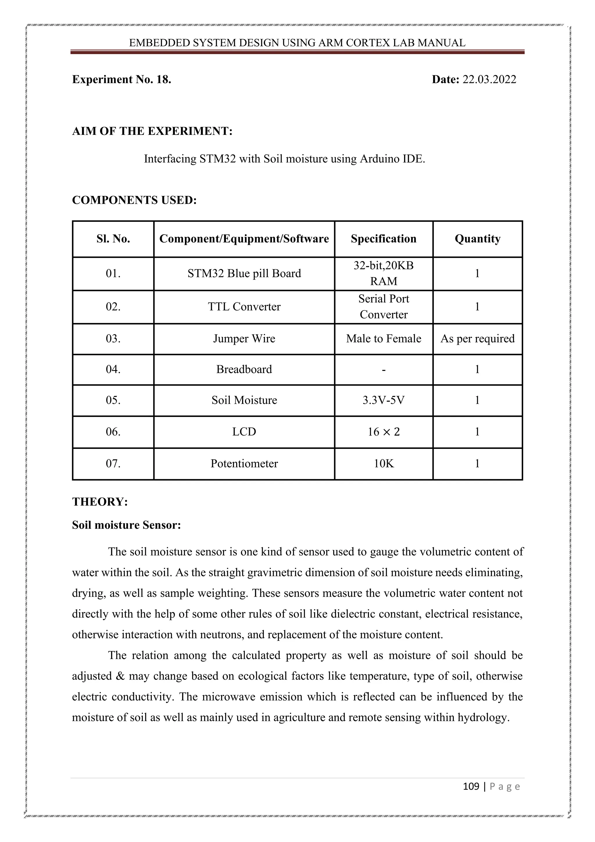
EMBEDDED SYSTEM DESIGNUSING ARM CORTEX LAB MANUAL 109 | P a g e Experiment No. 18. Date: 22.03.2022 AIM OF THE EXPERIMENT: Interfacing STM32 with Soil moisture using Arduino IDE. COMPONENTS USED: Sl. No. Component/Equipment/Software Specification Quantity 01. STM32 Blue pill Board 32-bit,20KB RAM 1 02. TTL Converter Serial Port Converter 1 03. Jumper Wire Male to Female As per required 04. Breadboard - 1 05. Soil Moisture 3.3V-5V 1 06. LCD 16 × 2 1 07. Potentiometer 10K 1 THEORY: Soil moisture Sensor: The soil moisture sensor is one kind of sensor used to gauge the volumetric content of water within the soil. As the straight gravimetric dimension of soil moisture needs eliminating, drying, as well as sample weighting. These sensors measure the volumetric water content not directly with the help of some other rules of soil like dielectric constant, electrical resistance, otherwise interaction with neutrons, and replacement of the moisture content. The relation among the calculated property as well as moisture of soil should be adjusted & may change based on ecological factors like temperature, type of soil, otherwise electric conductivity. The microwave emission which is reflected can be influenced by the moisture of soil as well as mainly used in agriculture and remote sensing within hydrology.
110.
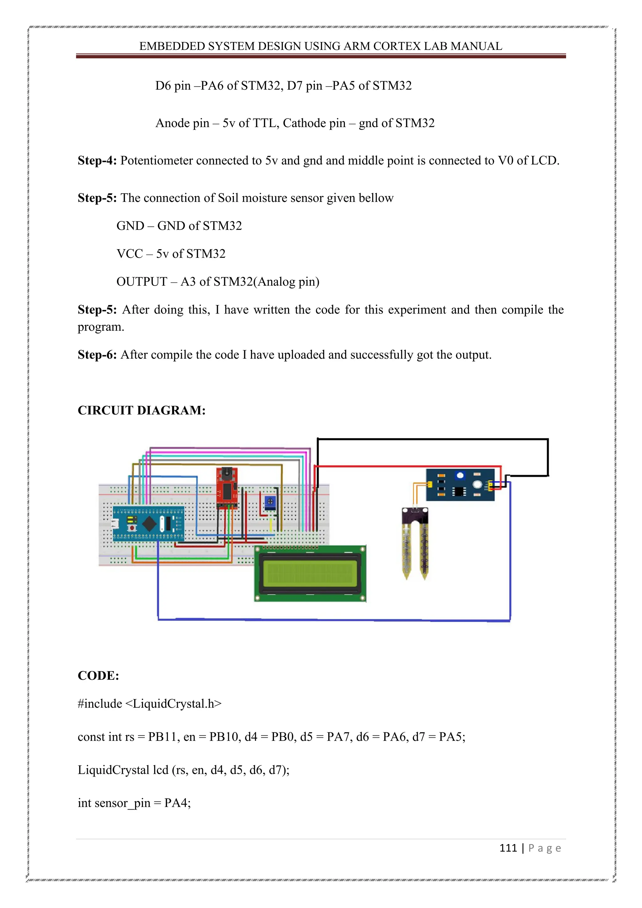
EMBEDDED SYSTEM DESIGNUSING ARM CORTEX LAB MANUAL 110 | P a g e These sensors normally used to check volumetric water content, and another group of sensors calculates a new property of moisture within soils named water potential. Generally, these sensors are named as soil water potential sensors which include gypsum blocks and tensiometer. The FC-28 soil moisture sensor includes 4-pins • VCC pin is used for power • A0 pin is an analog output • D0 pin is a digital output • GND pin is a Ground This module also includes a potentiometer that will fix the threshold value, & the value can be evaluated by the comparator-LM393. The LED will turn on/off based on the threshold value. Specifications The specification of this sensor includes the following. • The required voltage for working is 5V • The required current for working is <20mA • Type of interface is analog • The required working temperature of this sensor is 10°C~30°C PROCEDURE: Step-1: First I have connected the RX and TX pin of the TTL converter with STM32 A9pin and A10 pin respectively. Step-2: Then I have connected the ground and VCC pin of the TTL converter with STM32 Ground and 3.3v pin respectively. Step-3: After that, I have connected the respective pin of the LCD i.e., Rs pin – PB11 of STM32, E pin - PB10 of STM32 D4 pin –PB0 of STM32, D5 pin –PA7 of STM32
111.
EMBEDDED SYSTEM DESIGNUSING ARM CORTEX LAB MANUAL 111 | P a g e D6 pin –PA6 of STM32, D7 pin –PA5 of STM32 Anode pin – 5v of TTL, Cathode pin – gnd of STM32 Step-4: Potentiometer connected to 5v and gnd and middle point is connected to V0 of LCD. Step-5: The connection of Soil moisture sensor given bellow GND – GND of STM32 VCC – 5v of STM32 OUTPUT – A3 of STM32(Analog pin) Step-5: After doing this, I have written the code for this experiment and then compile the program. Step-6: After compile the code I have uploaded and successfully got the output. CIRCUIT DIAGRAM: CODE: #include <LiquidCrystal.h> const int rs = PB11, en = PB10, d4 = PB0, d5 = PA7, d6 = PA6, d7 = PA5; LiquidCrystal lcd (rs, en, d4, d5, d6, d7); int sensor_pin = PA4;
112.
EMBEDDED SYSTEM DESIGNUSING ARM CORTEX LAB MANUAL 112 | P a g e int output_value ; void setup() { lcd.begin(16, 2); lcd.setCursor(0, 0); lcd.print("Soil Moisture"); delay(3000); lcd.clear(); } void loop() { float moisture_percentage; int sensor_analog; sensor_analog = analogRead(sensor_pin); moisture_percentage = ( 100 - ( (sensor_analog / 1023.00) * 100 ) ); lcd.print("Moisture Percentage = "); lcd.print(moisture_percentage); lcd.print("%nn"); delay(1000); }
113.
EMBEDDED SYSTEM DESIGNUSING ARM CORTEX LAB MANUAL 113 | P a g e OUTPUT ON HARDWARE: Starting condition After upload the code
114.
EMBEDDED SYSTEM DESIGNUSING ARM CORTEX LAB MANUAL 114 | P a g e CONCLUSION: After completed this experiment, I got know about the Soil moisture sensor and its pinout and also learned that how to interface with STM32 board. Teacher’s Remark : Date of Submission: 23.03.2022 Students Signature : Hitesh Kumar Nath Regd. No. : 200301150005 Teacher’s Signature : Branch : EEE
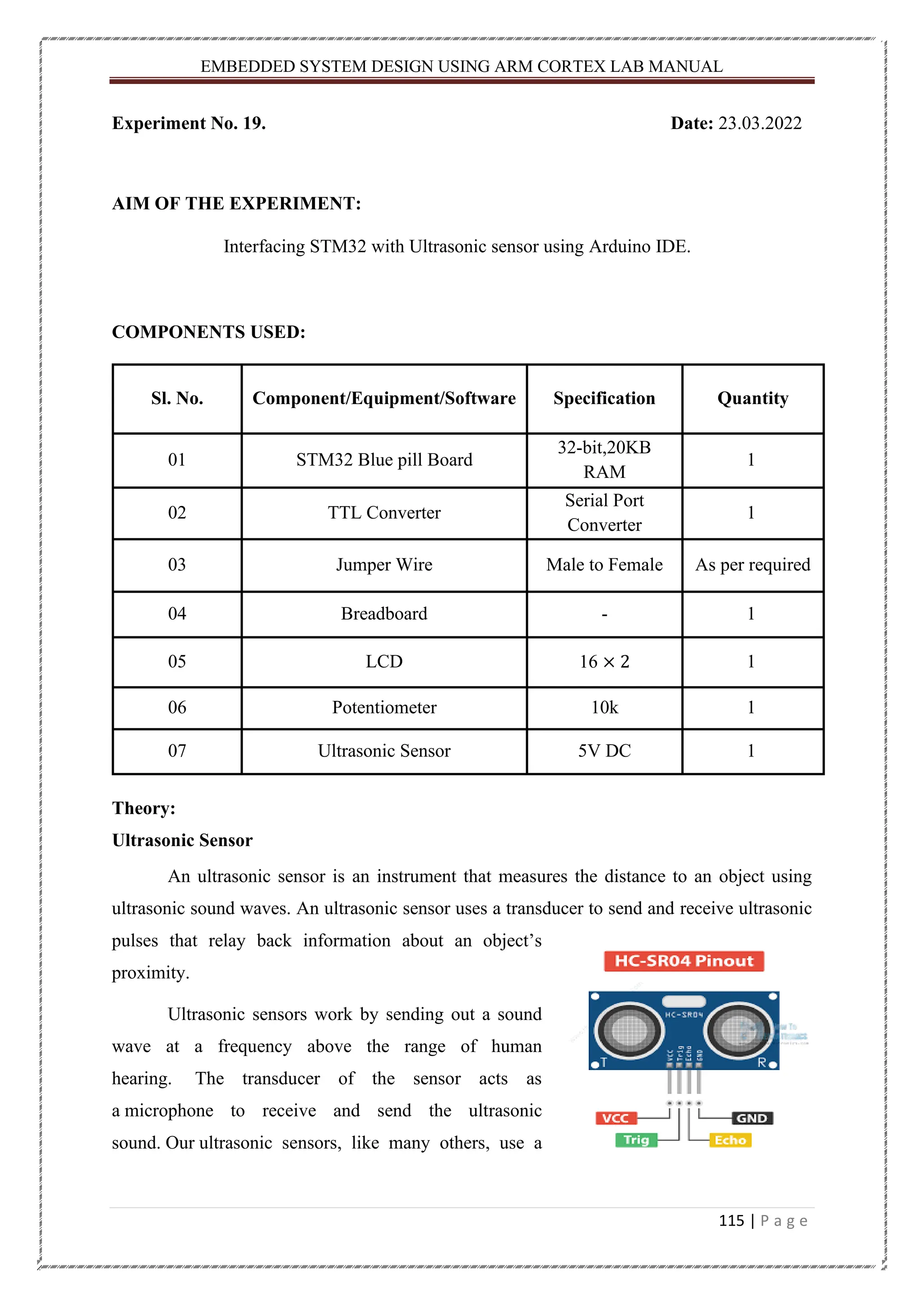
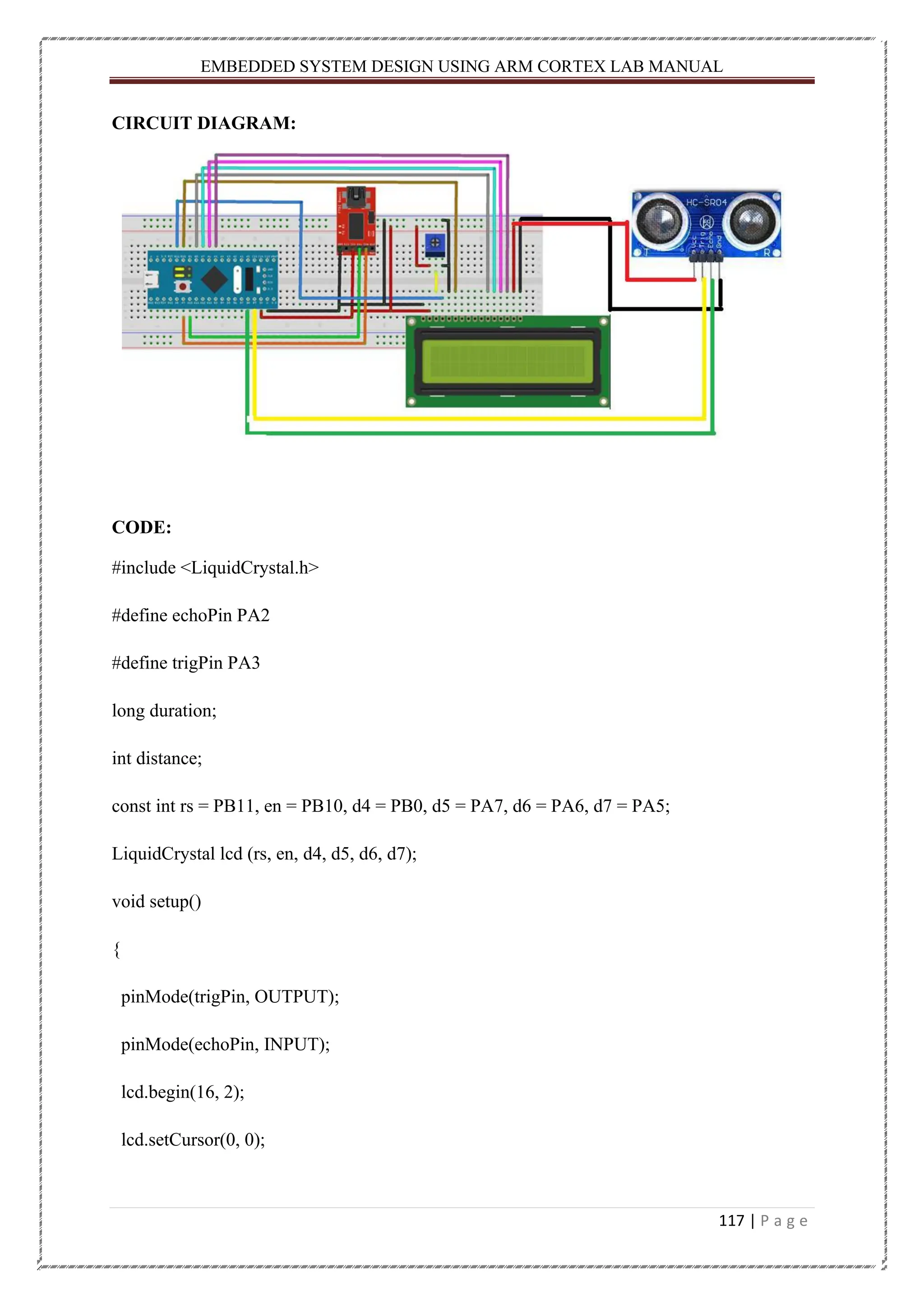
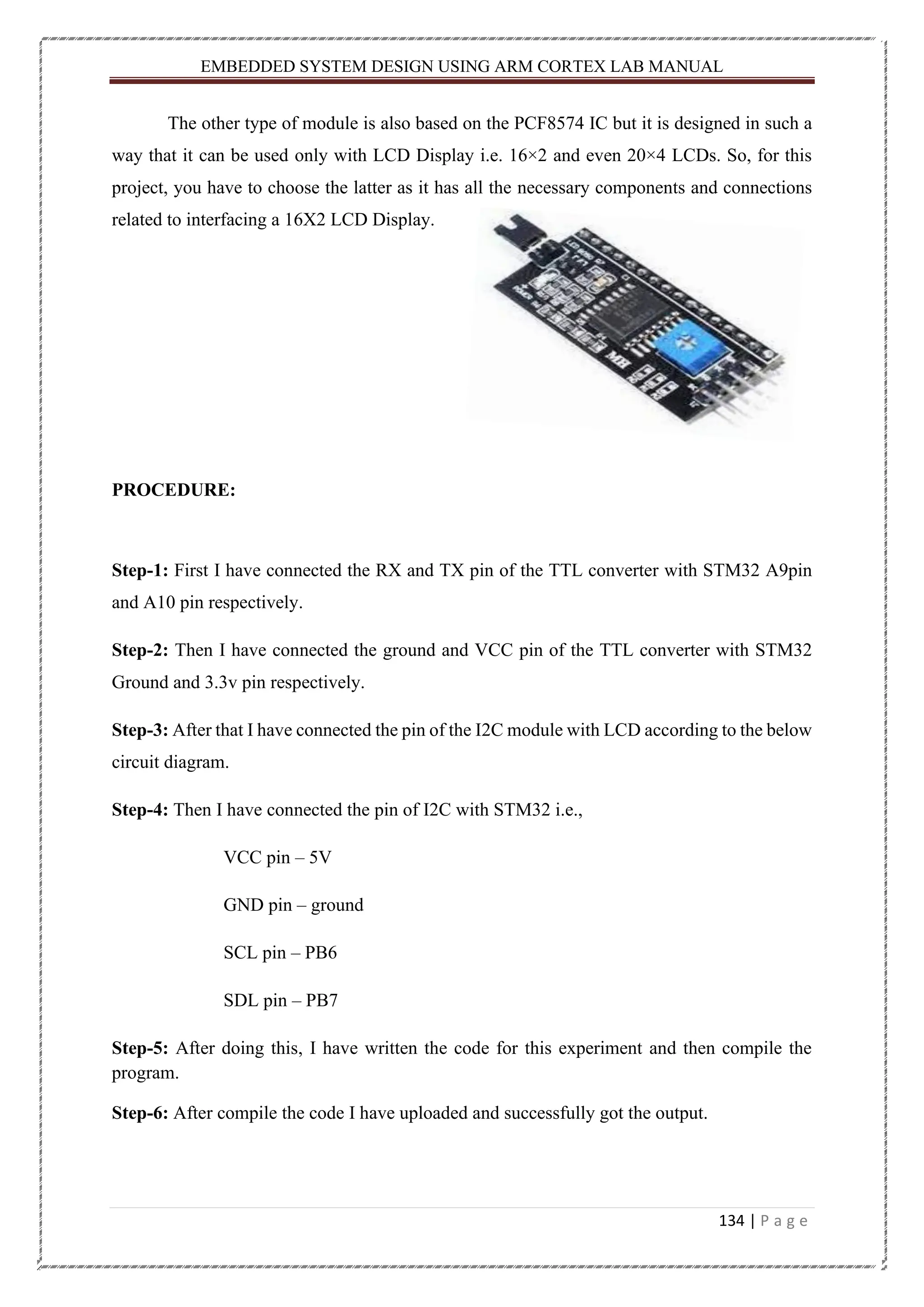
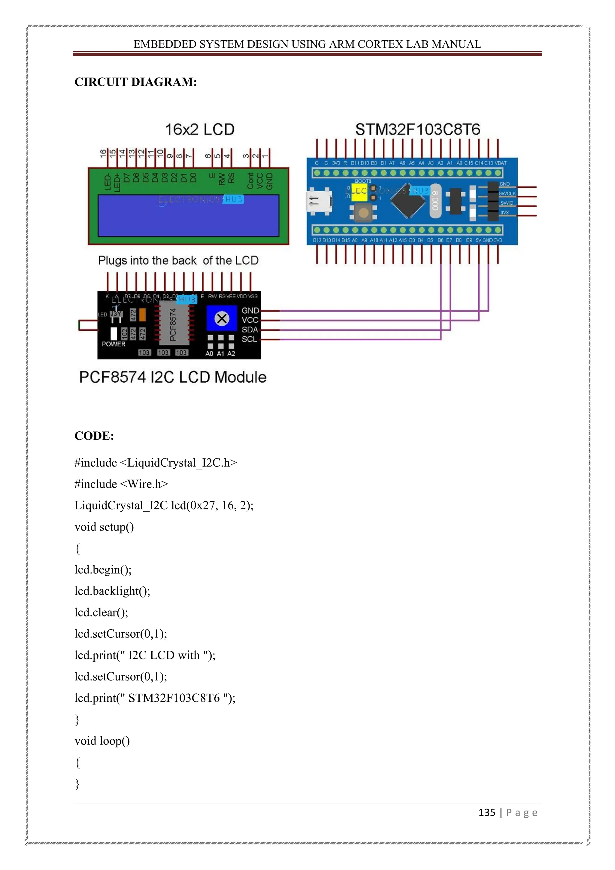
115.
EMBEDDED SYSTEM DESIGNUSING ARM CORTEX LAB MANUAL 115 | P a g e Experiment No. 19. Date: 23.03.2022 AIM OF THE EXPERIMENT: Interfacing STM32 with Ultrasonic sensor using Arduino IDE. COMPONENTS USED: Sl. No. Component/Equipment/Software Specification Quantity 01 STM32 Blue pill Board 32-bit,20KB RAM 1 02 TTL Converter Serial Port Converter 1 03 Jumper Wire Male to Female As per required 04 Breadboard - 1 05 LCD 16 × 2 1 06 Potentiometer 10k 1 07 Ultrasonic Sensor 5V DC 1 Theory: Ultrasonic Sensor An ultrasonic sensor is an instrument that measures the distance to an object using ultrasonic sound waves. An ultrasonic sensor uses a transducer to send and receive ultrasonic pulses that relay back information about an object’s proximity. Ultrasonic sensors work by sending out a sound wave at a frequency above the range of human hearing. The transducer of the sensor acts as a microphone to receive and send the ultrasonic sound. Our ultrasonic sensors, like many others, use a
116.
EMBEDDED SYSTEM DESIGNUSING ARM CORTEX LAB MANUAL 116 | P a g e single transducer to send a pulse and to receive the echo. The sensor determines the distance to a target by measuring time lapses between the sending and receiving of the ultrasonic pulse. The sensor has 4 pins. VCC and GND go to 5V and GND pins on the Arduino, and the Trig and Echo go to any digital Arduino pin. Using the Trig pin we send the ultrasound wave from the transmitter, and with the Echo pin we listen for the reflected signal. As we connect the module to 5V and initialize the input pin, it starts transmitting the sound waves which then travel through the air and hit the required object. These waves hit and bounce back from the object and then collected by the receiver of the module. PROCEDURE: Step-1: First I have connected the RX and TX pin of the TTL converter with STM32 A9pin and A10 pin respectively. Step-2: Then I have connected the ground and VCC pin of the TTL converter with STM32 Ground and 3.3v pin respectively. Step-3: After that, I have connected the respective pin of the LCD i.e., Rs pin – PB11 of STM32, E pin - PB10 of STM32 D4 pin –PB0 of STM32, D5 pin –PA7 of STM32 D6 pin –PA6 of STM32, D7 pin –PA5 of STM32 Anode pin – 5v of TTL, Cathode pin – gnd of STM32 Step-4: Then, I have connected the pin of ultrasonic sensor with STM32 board i.e., Echo pin – PA2 and Trig pin – PA3 and VCC and GND pin connected 5v and ground respectively. Step-5: After doing this, I have written the code for this experiment and then compile the program. Step-6: After compile the code I have uploaded and successfully got the output.
117.
EMBEDDED SYSTEM DESIGNUSING ARM CORTEX LAB MANUAL 117 | P a g e CIRCUIT DIAGRAM: CODE: #include <LiquidCrystal.h> #define echoPin PA2 #define trigPin PA3 long duration; int distance; const int rs = PB11, en = PB10, d4 = PB0, d5 = PA7, d6 = PA6, d7 = PA5; LiquidCrystal lcd (rs, en, d4, d5, d6, d7); void setup() { pinMode(trigPin, OUTPUT); pinMode(echoPin, INPUT); lcd.begin(16, 2); lcd.setCursor(0, 0);
118.
EMBEDDED SYSTEM DESIGNUSING ARM CORTEX LAB MANUAL 118 | P a g e lcd.print("UltraSonic Sensor"); delay(3000); lcd.clear(); } void loop() { digitalWrite(trigPin, LOW); //generate square wave at trigger pin delayMicroseconds(2); digitalWrite(trigPin, HIGH); delayMicroseconds(10); digitalWrite(trigPin, LOW); duration = pulseIn(echoPin, HIGH); //calculation of distance of obstacle distance = (duration * 0.034 / 2); lcd.setCursor(0, 0); lcd.print("Distance : "); lcd.print(distance); lcd.println(" cm "); delay(1000); }
EMBEDDED SYSTEM DESIGNUSING ARM CORTEX LAB MANUAL 120 | P a g e CONCLUSION: After completed this experiment, I got know about the Ultrasonic sensor and it’s pinout and also learned that how to interface with STM32 board. Teacher’s Remark : Date of Submission: 29.03.2022 Students Signature : Hitesh Kumar Nath Regd. No. : 200301150005 Teacher’s Signature : Branch : EEE
121.
EMBEDDED SYSTEM DESIGNUSING ARM CORTEX LAB MANUAL 121 | P a g e Experiment No. 20. Date: 29.03.2022 AIM OF THE EXPERIMENT: Interfacing STM32 with GPS module using Arduino IDE. COMPONENTS USED: Sl. No. Component/Equipment/Software Specification Quantity 01 STM32 Blue pill Board 32-bit,20KB RAM 1 02 TTL Converter Serial Port Converter 1 03 Jumper Wire Male to Female As per required 04 Breadboard - 1 05 LCD 16 × 2 1 06 Potentiometer 10K 1 07 GPS Module 2.7V-6V 1 Theory: GPS Module GPS stands for Global Positioning System and used to detect the Latitude and Longitude of any location on the Earth, with exact UTC time (Universal Time Coordinated). This device receives the coordinates from the satellite for each and every second, with time and date. GPS offers great accuracy and also provides other data besides position coordinates. It’s a GY-NEO6MV2 XM37-1612 GPS Module. This GPS module has four pin +5V, GND, TXD and RXD. It communicates using the Serial pins and can be easily interfaced with the Serial port of the STM32F103C8. GPS module sends the data in NMEA format (see the screenshot below). NMEA format consist several sentences, in which we only need one sentence. This sentence starts from $GPGGA and contains the coordinates, time and other useful information. This GPGGA is referred to Global Positioning System Fix Data. • GND is the Ground Pin and needs to be connected to GND pin on the Arduino. • TXD (Transmitter) pin is used for serial communication.
122.
EMBEDDED SYSTEM DESIGNUSING ARM CORTEX LAB MANUAL 122 | P a g e • RXD (Receiver) pin is used for serial communication. • VCC supplies power for the module. You can directly connect it to the 5V pin on the Arduino. PROCEDURE: Step-1: First I have connected the RX and TX pin of the TTL converter with STM32 A9pin and A10 pin respectively. Step-2: Then I have connected the ground and VCC pin of the TTL converter with STM32 Ground and 3.3v pin respectively. Step-3: After that, I have connected the respective pin of the LCD i.e., Rs pin – PB11 of STM32, E pin - PB10 of STM32 D4 pin –PB0 of STM32, D5 pin –PA7 of STM32 D6 pin –PA6 of STM32, D7 pin –PA5 of STM32 Anode pin – 5v of TTL, Cathode pin – gnd of STM32 Step-4: Then, I have connected the pin of GPS module with STM32 board i.e., RX pin – A9, TX pin – A10, +5v pin – 5v and GND pin – ground. Step-5: After doing this, I have written the code for this experiment and then compile the program. Step-6: After compile the code I have uploaded and successfully got the output.
123.
EMBEDDED SYSTEM DESIGNUSING ARM CORTEX LAB MANUAL 123 | P a g e CIRCUIT DIAGRAM: CODE: #include <LiquidCrystal.h> #include <TinyGPS++.h> const int rs = PB11, en = PB10, d4 = PB0, d5 = PA7, d6 = PA6, d7 = PA5; LiquidCrystal lcd (rs, en, d4, d5, d6, d7); TinyGPSPlus gps; void setup() { Serial1.begin(9600); lcd.begin(16,2); lcd.print("Circuit Digest"); lcd.setCursor(0,1); lcd.print("STM32 with GPS"); delay(4000); lcd.clear(); }
124.
EMBEDDED SYSTEM DESIGNUSING ARM CORTEX LAB MANUAL 124 | P a g e void loop() { GPSDelay(1000); unsigned long start; double lat_val, lng_val; bool loc_valid; lat_val = gps.location.lat(); loc_valid = gps.location.isValid(); lng_val = gps.location.lng(); if (!loc_valid) { lcd.print("Waiting"); Serial.print("Latitude : "); Serial.println("*****"); Serial.print("Longitude : "); Serial.println("*****"); delay(4000); lcd.clear(); } else { lcd.clear(); Serial.println("GPS READING: "); Serial.print("Latitude : "); Serial.println(lat_val, 6); lcd.setCursor(0,0); lcd.print("LAT:"); lcd.print(lat_val,6); Serial.print("Longitude : "); Serial.println(lng_val, 6); lcd.setCursor(0,1); lcd.print("LONG:"); lcd.print(lng_val,6); delay(4000);
125.
EMBEDDED SYSTEM DESIGNUSING ARM CORTEX LAB MANUAL 125 | P a g e } } static void GPSDelay(unsigned long ms) { unsigned long start = millis(); do { while (Serial1.available()) gps.encode(Serial1.read()); } while (millis() - start < ms); } OUTPUT ON HARDWARE:
126.
EMBEDDED SYSTEM DESIGNUSING ARM CORTEX LAB MANUAL 126 | P a g e CONCLUSION: After completed this experiment, I got know about the GPS Module and its pinout and learned that how to interface with STM32 board. Teacher’s Remark : Date of Submission: 30.03.2022 Students Signature : Hitesh Kumar Nath Regd. No. : 200301150005 Teacher’s Signature : Branch : EEE
127.
EMBEDDED SYSTEM DESIGNUSING ARM CORTEX LAB MANUAL 127 | P a g e Experiment No. 21. Date: 30.03.2022 AIM OF THE EXPERIMENT: Interfacing STM32 with Bluetooth module using Arduino IDE. COMPONENTS USED: Sl. No. Component/Equipment/Software Specification Quantity 01 STM32 Blue pill Board Micro-controller 1 02 TTL Converter Serial Port Converter 1 03 Jumper Wire Male to Female As per required 04 Breadboard - 1 05 Bluetooth Module HC-05 1 06 Bluetooth Terminal app - - 07 LED Yellow 1 THEORY: Bluetooth Module (HC-05) ➔ It is mostly used Bluetooth module in embedded projects. It is a serial Bluetooth module that uses serial communication having range less than 100m and operates at 5V (3.3V minimum). It can be used to connect two microcontrollers wirelessly and also with mobile phone and laptops. As there are many android applications are available, it is very useful for making wireless Bluetooth controlled projects. ➔ It uses USART communication and can be interfaced with microcontrollers having USART communication protocol. ➔ It has an integrated antenna. It has Master/Slave configurations that can be changed in AT command mode that is useful when only one device should send the data (master to slave)
128.
EMBEDDED SYSTEM DESIGNUSING ARM CORTEX LAB MANUAL 128 | P a g e like for example from PC (MASTER) to slave (any MCU). A master can connect to other devices and slave doesn’t connect to other connection other than master. Modes of Operation ➔ It has two modes AT Command Mode & Data Mode. ➔ When Bluetooth is powered up it enters data mode default. This mode can be used for data transfers. To enter into AT Command mode during power up we need to press the button present in module to change the default settings of the module like master/slave configurations. ➔ Pins of Bluetooth Module ▪ EN pin (ENABLE) -This pin is used to set Data Mode or AT Command Mode. By default, it is in DATA MODE. When button pressed during power up it goes to AT command mode. ▪ +5V pin- This is used for power supply to the module ▪ GND pin- This is used for ground for module ▪ TX pin- This pin to connected to RX pin of MCU ▪ RX pin- This pin connected to TX pin of MCU ▪ STATE- This pin indicates the status of the module, see below about indications
129.
EMBEDDED SYSTEM DESIGNUSING ARM CORTEX LAB MANUAL 129 | P a g e PROCEDURE: Step-1: First I have connected the RX and TX pin of the TTL converter with STM32 A9pin and A10 pin respectively. Step-2: Then I have connected the ground and VCC pin of the TTL converter with STM32 Ground and 3.3v pin respectively. Step-3: After uploading the program disconnect the RX and TX pin of TTL from STM32. Step-4: The connection of Bluetooth module given bellow GND – GND of STM board 3.3V – 3.3V of STM board RX - A9 of STM board TX – A10 of STM board Step-5: 1 led connected to A5 pin of STM32 board. Step-6: After doing this, I have written the code for this experiment and then compile the program. Step-7: After compile the code I have uploaded and successfully got the output. CIRCUIT DIAGRAM:
130.
EMBEDDED SYSTEM DESIGNUSING ARM CORTEX LAB MANUAL 130 | P a g e CODE: const int pinout = PA2; char inputdata = 0; void setup() { Serial1.begin(9600); Serial1.print("CIRCUIT DIGESTn"); Serial1.print("BLUETOOTH WITH STM32n"); pinMode(pinout, OUTPUT); } void loop() { if(Serial1.available() > 0) { inputdata = Serial1.read(); if(inputdata == '1') { digitalWrite(pinout, HIGH); Serial1.print("LED ONn"); } else if(inputdata == '0') { digitalWrite(pinout, LOW);
131.
EMBEDDED SYSTEM DESIGNUSING ARM CORTEX LAB MANUAL 131 | P a g e Serial1.print("LED OFFn"); } } } OUTPUT ON HARDWARE:
132.
EMBEDDED SYSTEM DESIGNUSING ARM CORTEX LAB MANUAL 132 | P a g e CONCLUSION: After completed this experiment, I got know about the Bluetooth Module and its pinout and learned that how to interface with STM32 board. Teacher’s Remark: Date of Submission: 05.04.2022 Students Signature : Hitesh Kumar Nath Regd. No. : 200301150005 Teacher’s Signature : Branch : EEE
133.
EMBEDDED SYSTEM DESIGNUSING ARM CORTEX LAB MANUAL 133 | P a g e Experiment No. 22. Date: 05.04.2022 AIM OF THE EXPERIMENT: Interfacing STM32 with I2C display using Arduino IDE. COMPONENTS USED: Sl. No. Component/Equipment/Software Specification Quantity 01 STM32 Blue pill Board Micro-controller 1 02 TTL Converter Serial Port Converter 1 03 Jumper Wire Male to Female As per required 04 Breadboard - 1 05 LCD 16 × 2 1 06 Potentiometer 10K 1 07 I2C Module PCF8574 1 Theory: PCF8574 Module I have already discussed about PCF8574 GPIO Expander IC in this “Interfacing PCF8574 with Arduino” tutorial. So, I will not go into the details but just a brief overview. The PCF8574 is a 16 pin IC that acts as an I2C to 8-bit Parallel IO expander. What this means that using I2C Communication from Microcontroller, you can effectively increase the number of IO pins of your Microcontroller by 8. An important thing to remember when buying a PCF8574 Module is that there are two types of them available in the market. One is a generic IO Expander Module, which can be used as, well an IO expander.
134.
EMBEDDED SYSTEM DESIGNUSING ARM CORTEX LAB MANUAL 134 | P a g e The other type of module is also based on the PCF8574 IC but it is designed in such a way that it can be used only with LCD Display i.e. 16×2 and even 20×4 LCDs. So, for this project, you have to choose the latter as it has all the necessary components and connections related to interfacing a 16X2 LCD Display. PROCEDURE: Step-1: First I have connected the RX and TX pin of the TTL converter with STM32 A9pin and A10 pin respectively. Step-2: Then I have connected the ground and VCC pin of the TTL converter with STM32 Ground and 3.3v pin respectively. Step-3: After that I have connected the pin of the I2C module with LCD according to the below circuit diagram. Step-4: Then I have connected the pin of I2C with STM32 i.e., VCC pin – 5V GND pin – ground SCL pin – PB6 SDL pin – PB7 Step-5: After doing this, I have written the code for this experiment and then compile the program. Step-6: After compile the code I have uploaded and successfully got the output.
135.
EMBEDDED SYSTEM DESIGNUSING ARM CORTEX LAB MANUAL 135 | P a g e CIRCUIT DIAGRAM: CODE: #include <LiquidCrystal_I2C.h> #include <Wire.h> LiquidCrystal_I2C lcd(0x27, 16, 2); void setup() { lcd.begin(); lcd.backlight(); lcd.clear(); lcd.setCursor(0,1); lcd.print(" I2C LCD with "); lcd.setCursor(0,1); lcd.print(" STM32F103C8T6 "); } void loop() { }
EMBEDDED SYSTEM DESIGNUSING ARM CORTEX LAB MANUAL 137 | P a g e CONCLUSION: After completed this experiment, I got know about the I2C LCD Module and its pinout and learned that how to interface with STM32 board. Teacher’s Remark : Date of Submission: 07.04.2022 Students Signature : Hitesh Kumar Nath Regd. No. : 200301150005 Teacher’s Signature : Branch : EEE
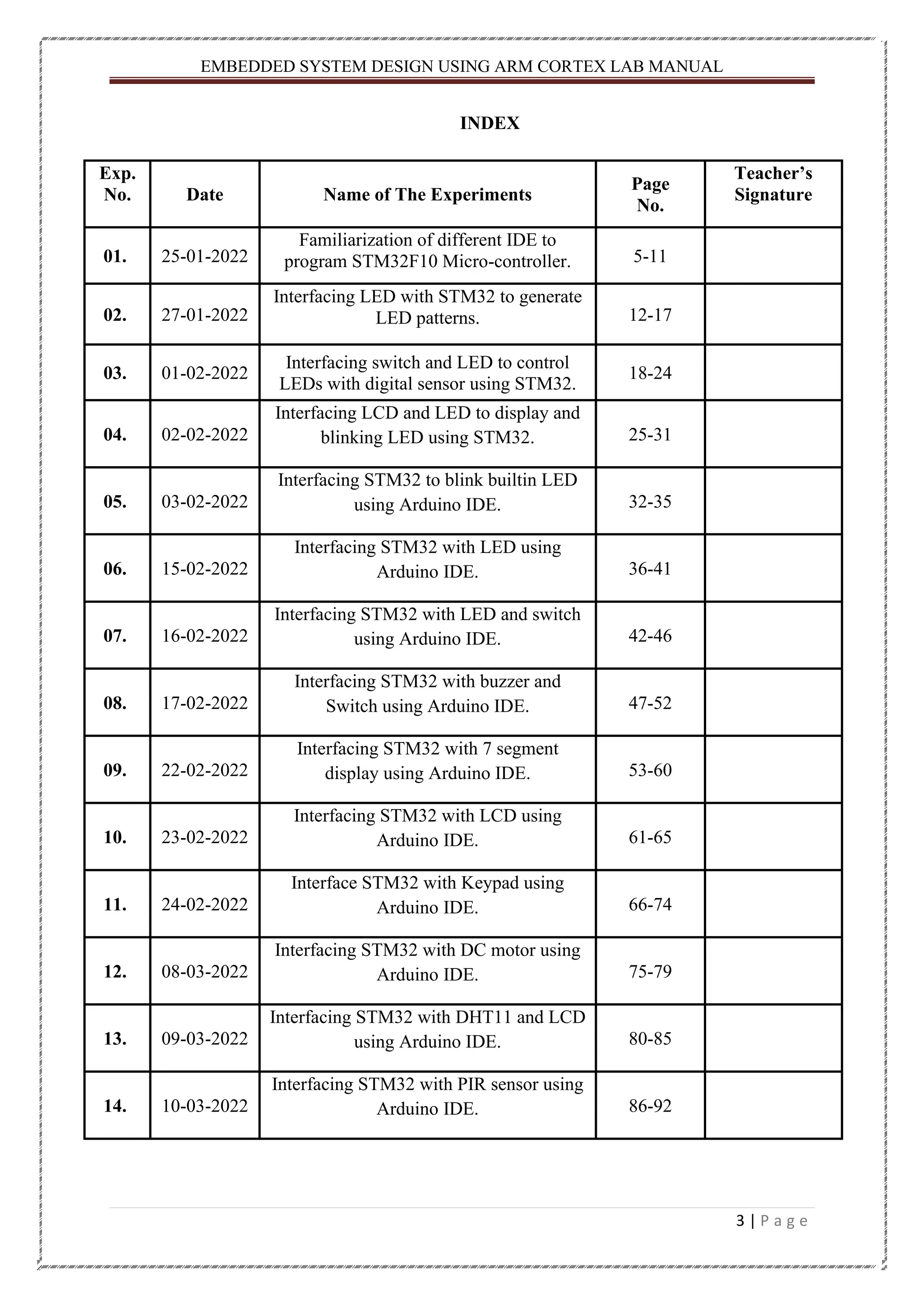
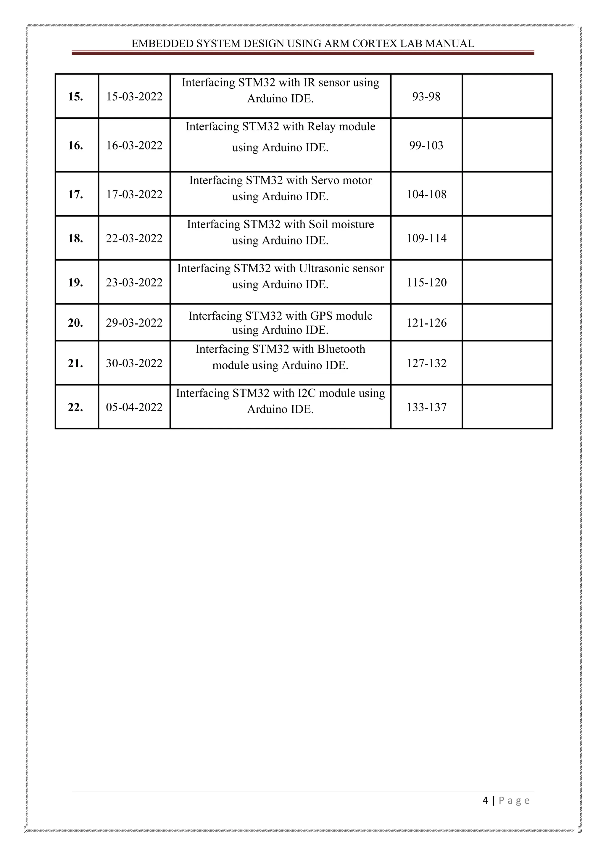
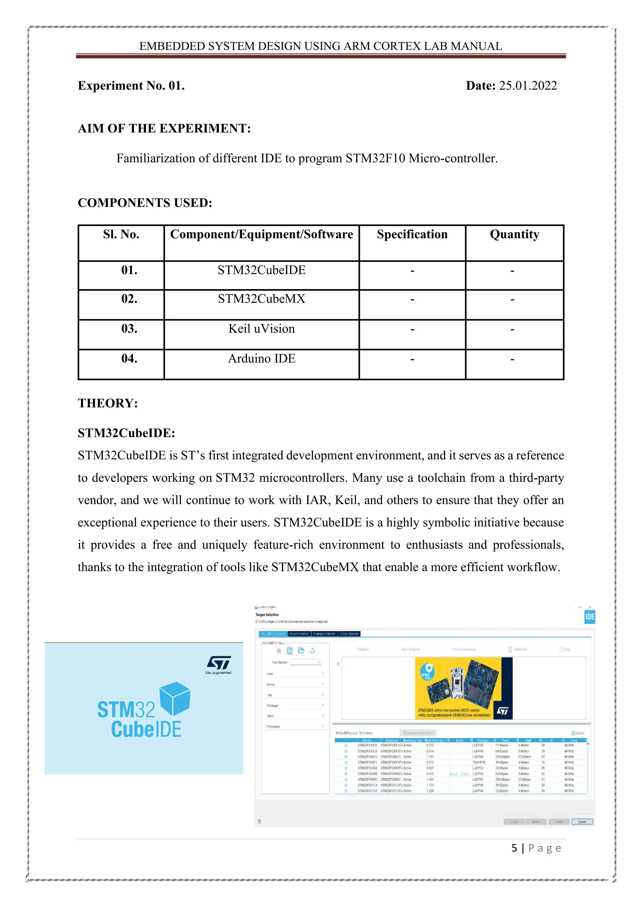
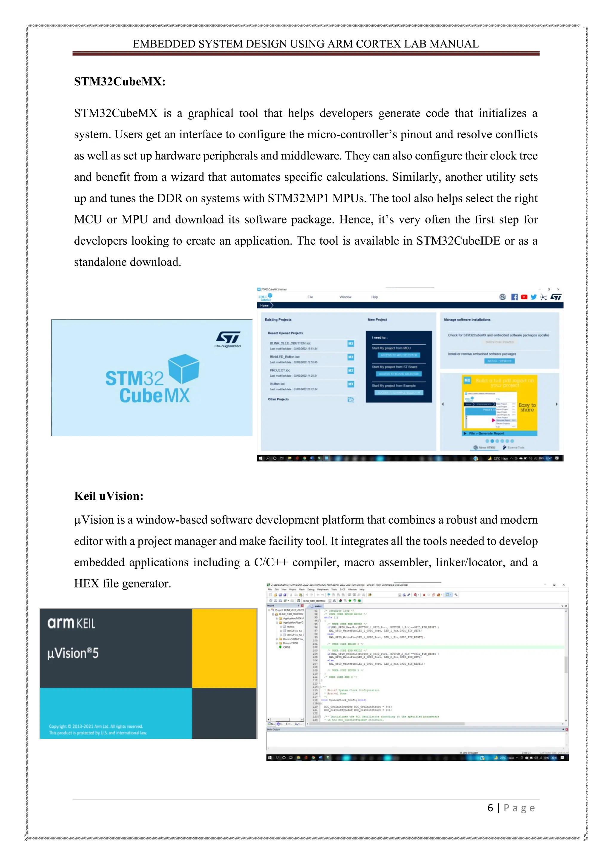
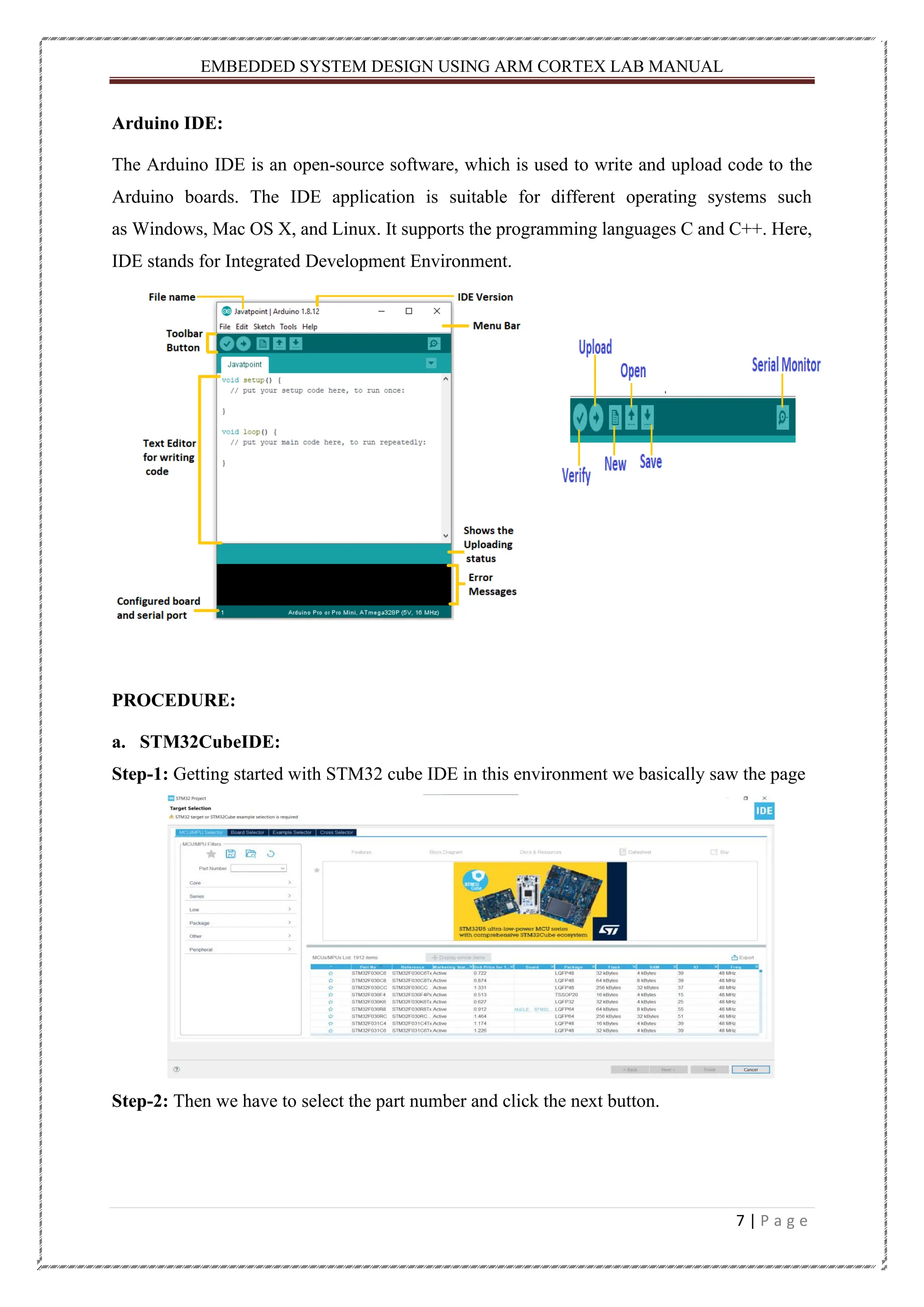
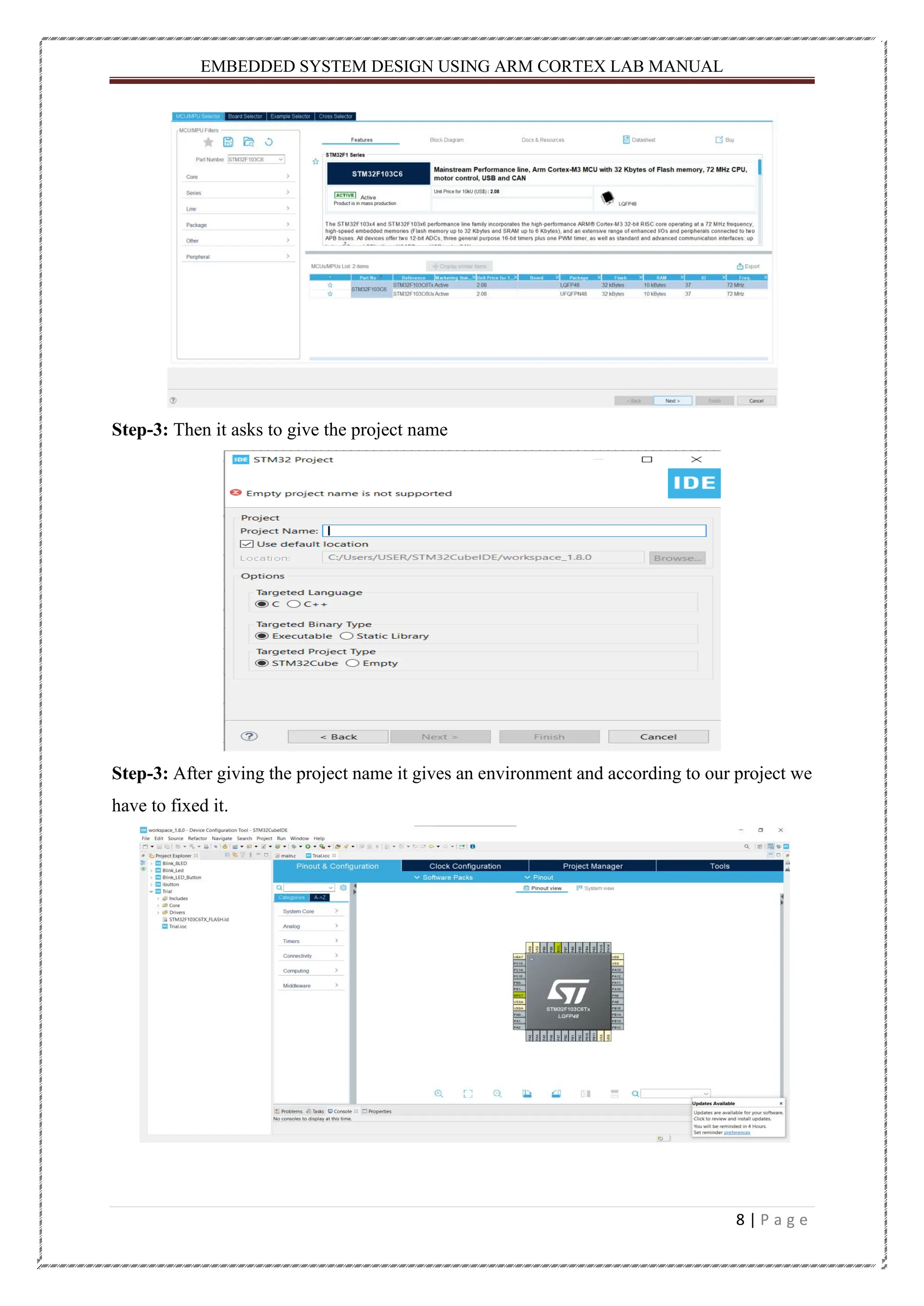

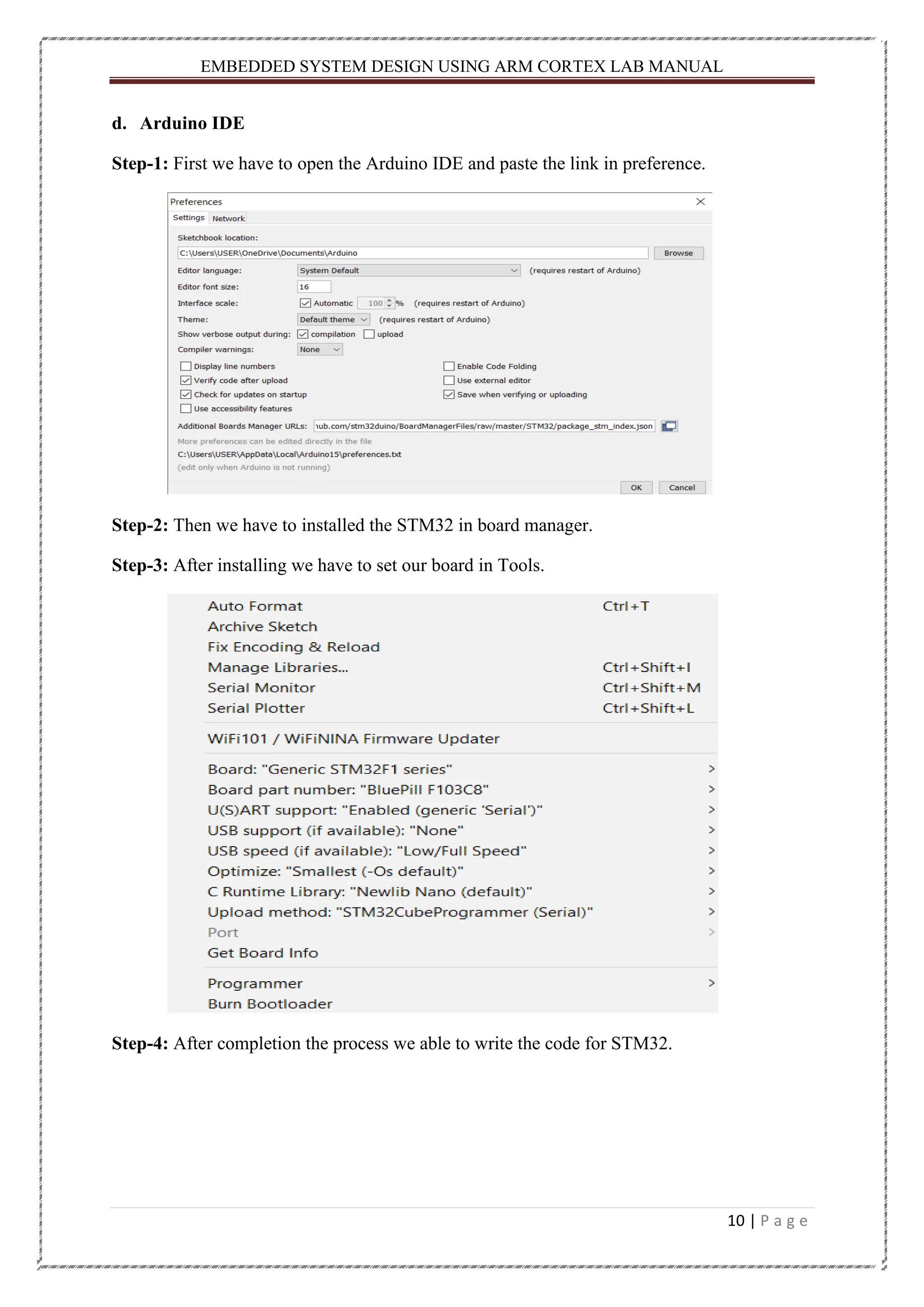

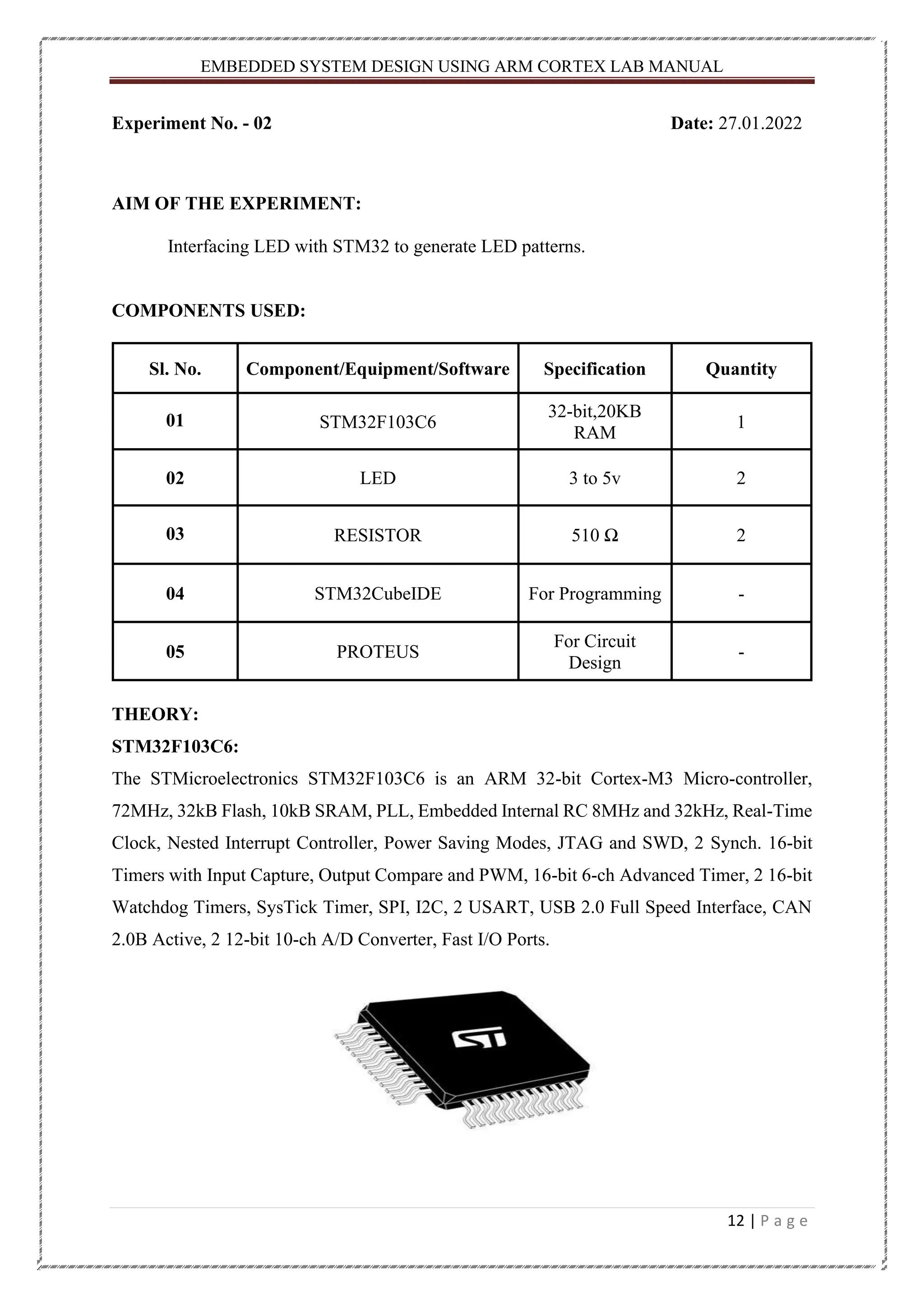
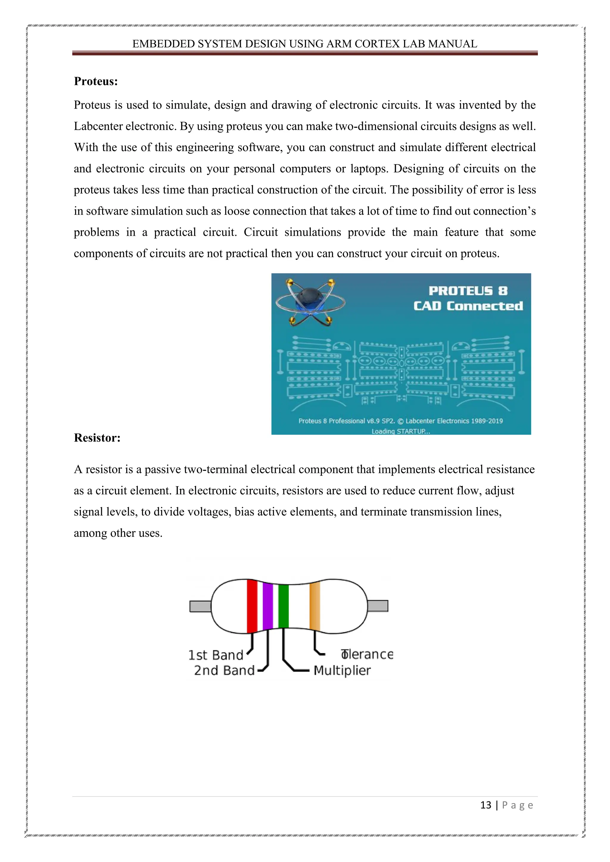
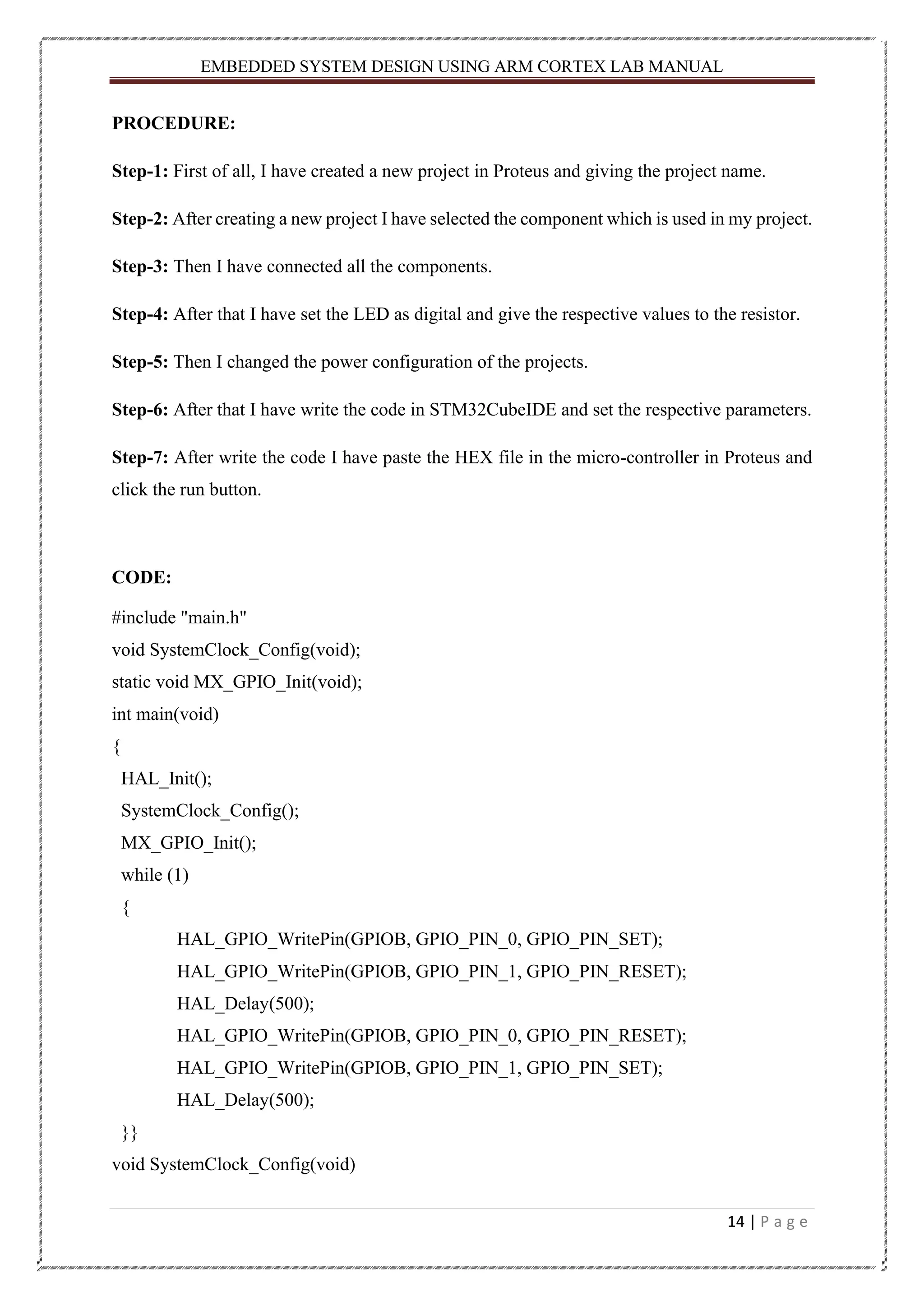
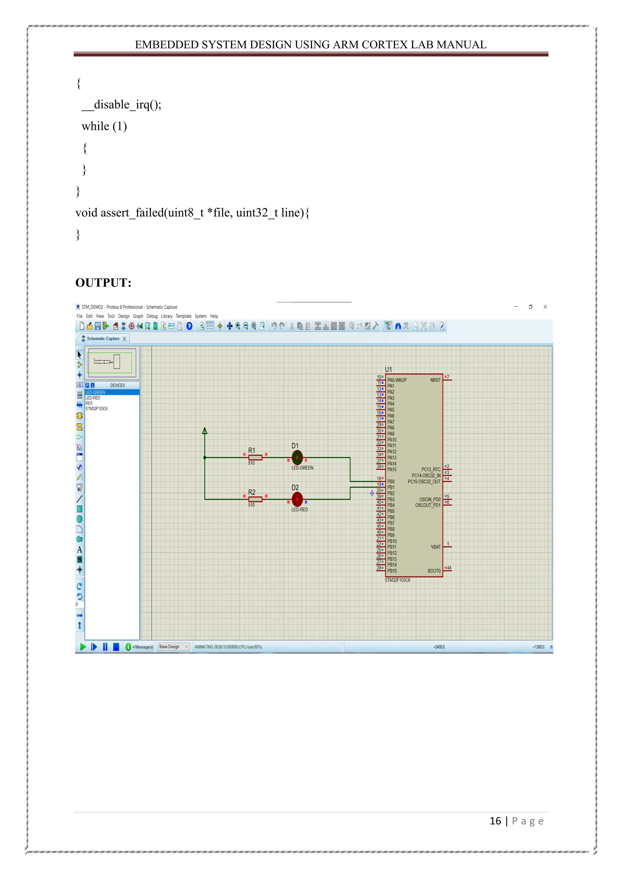
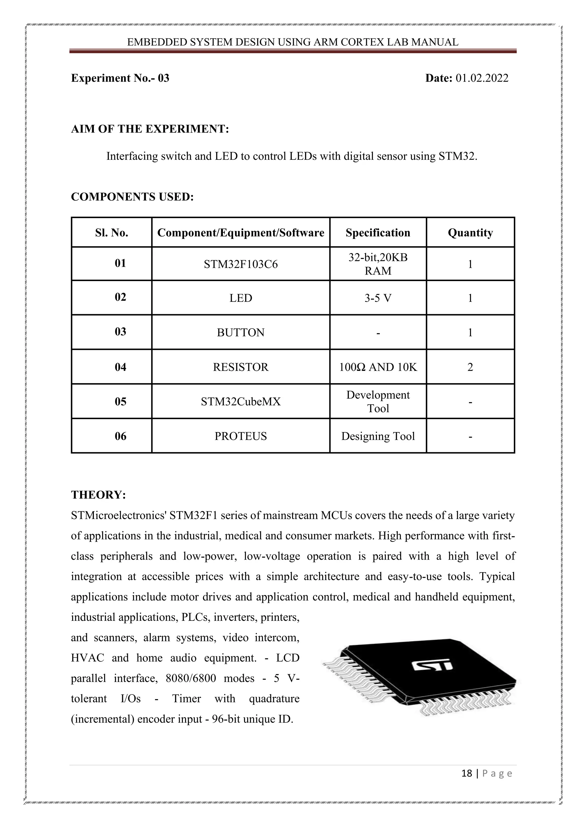
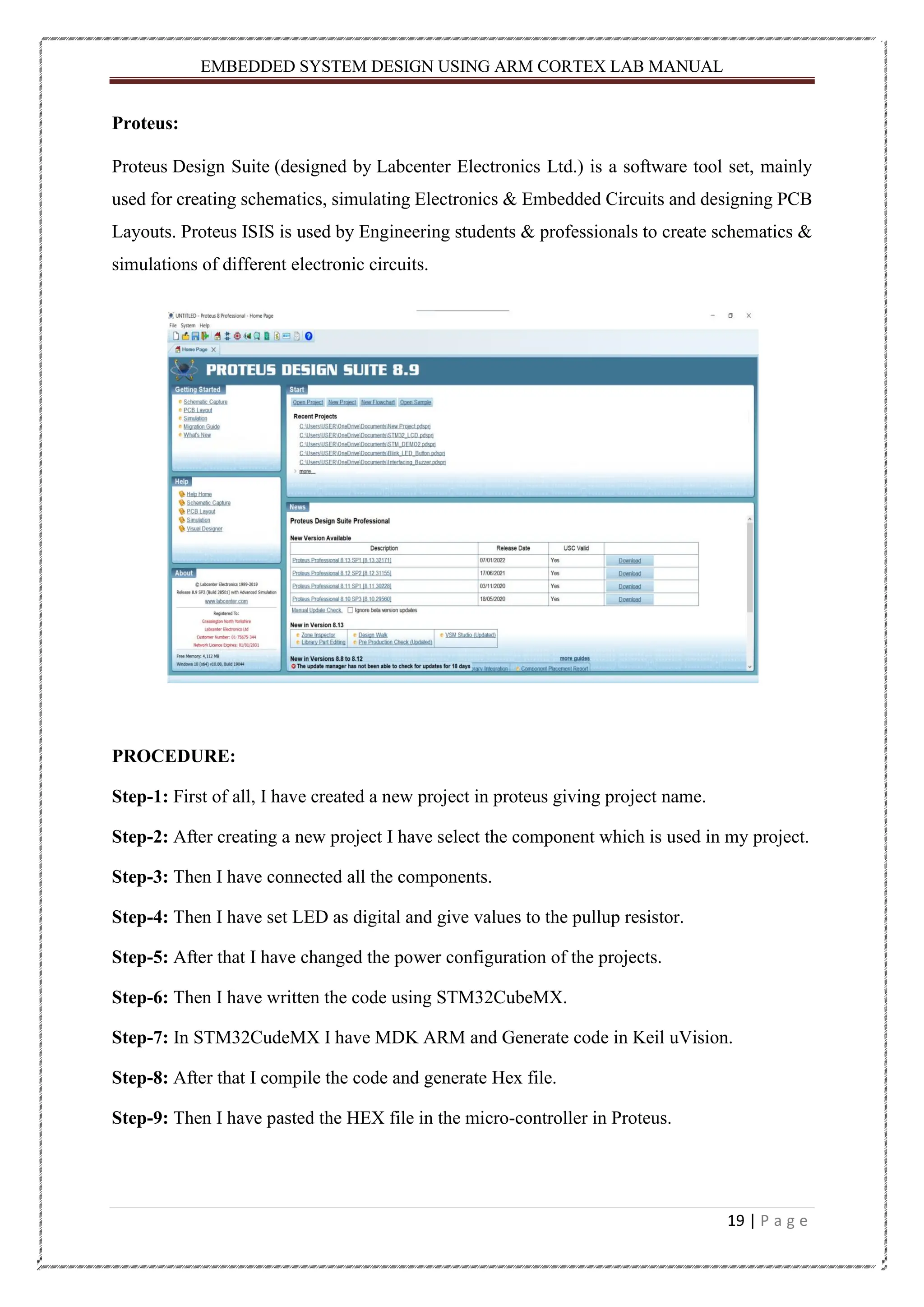
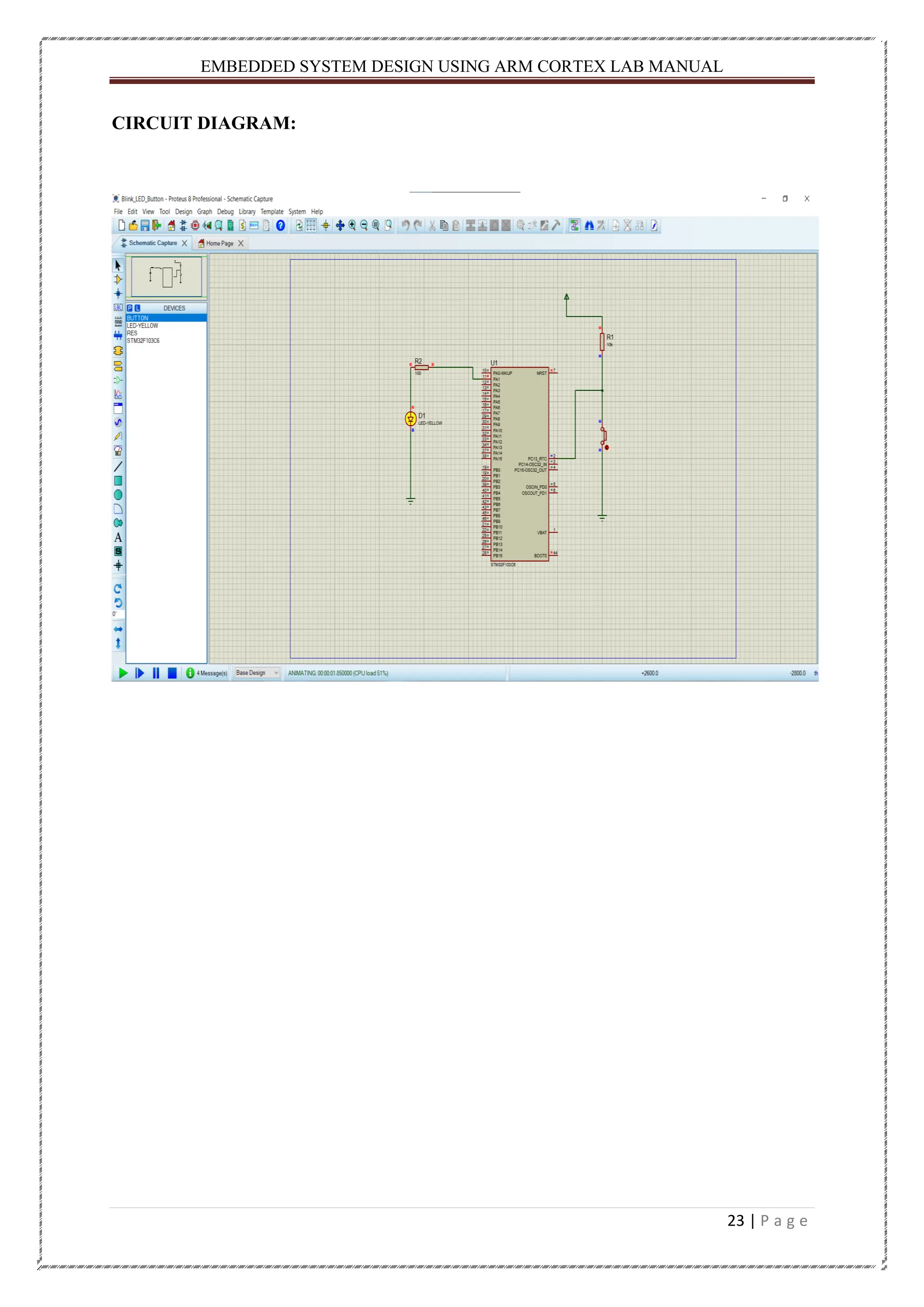
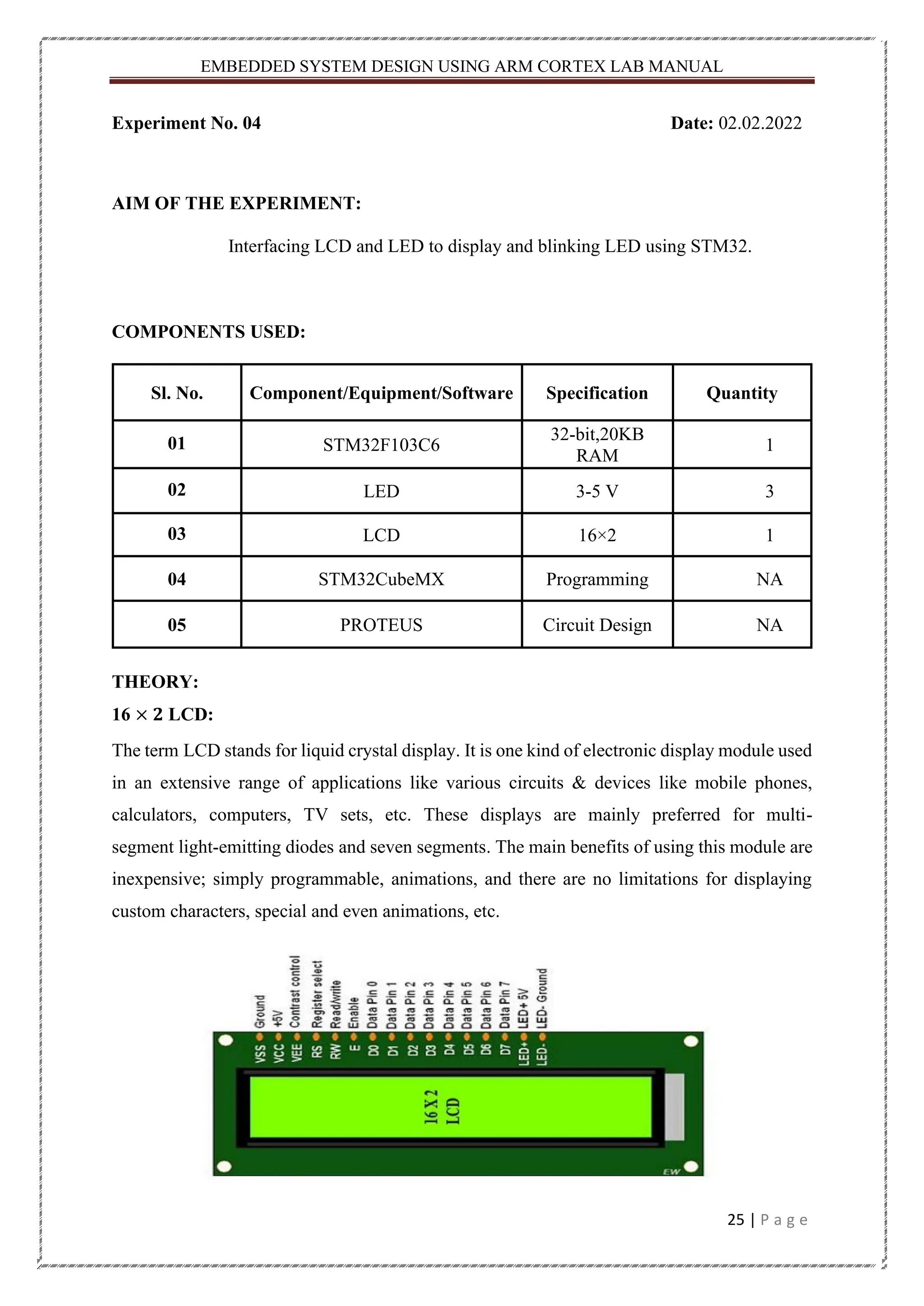
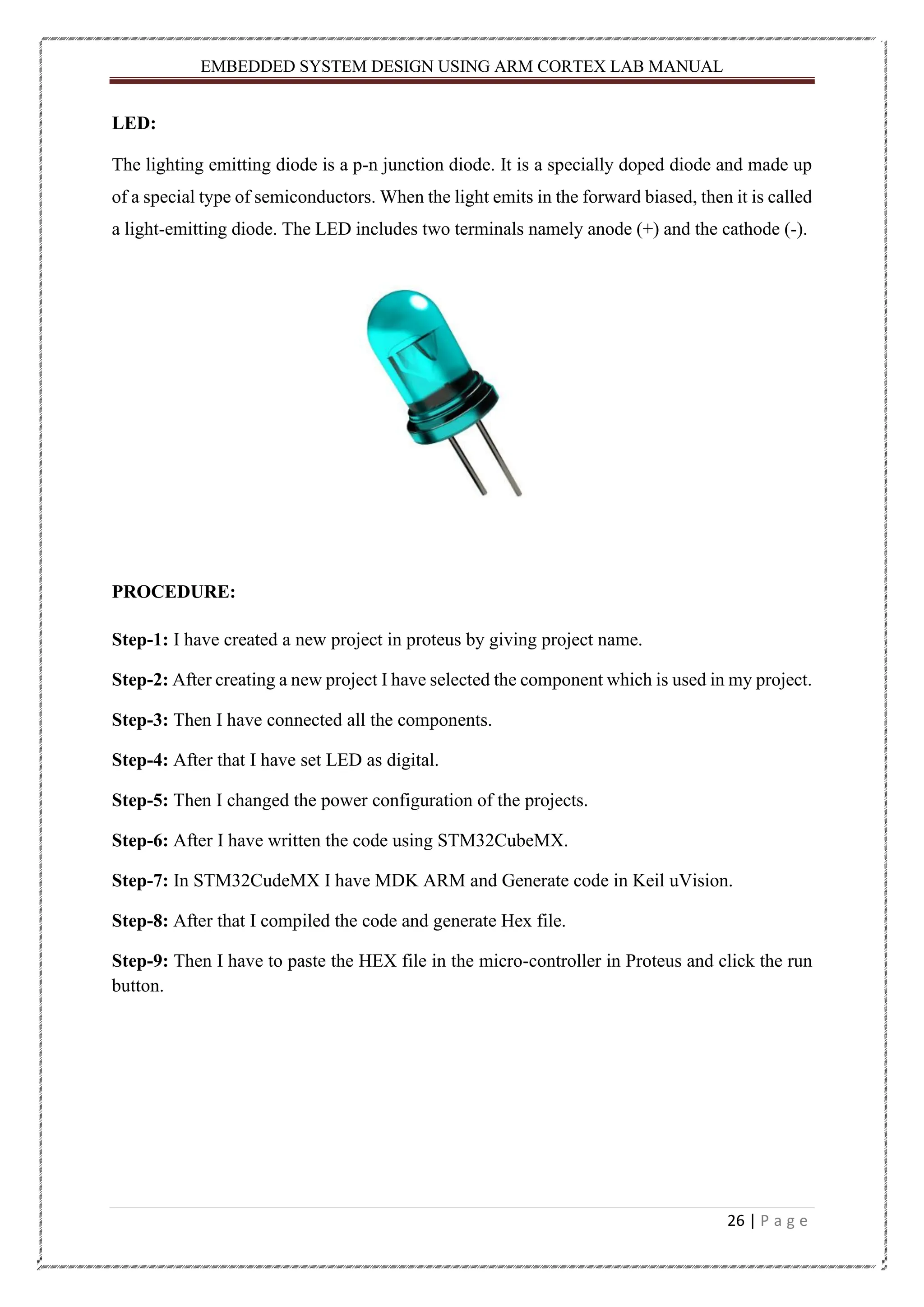


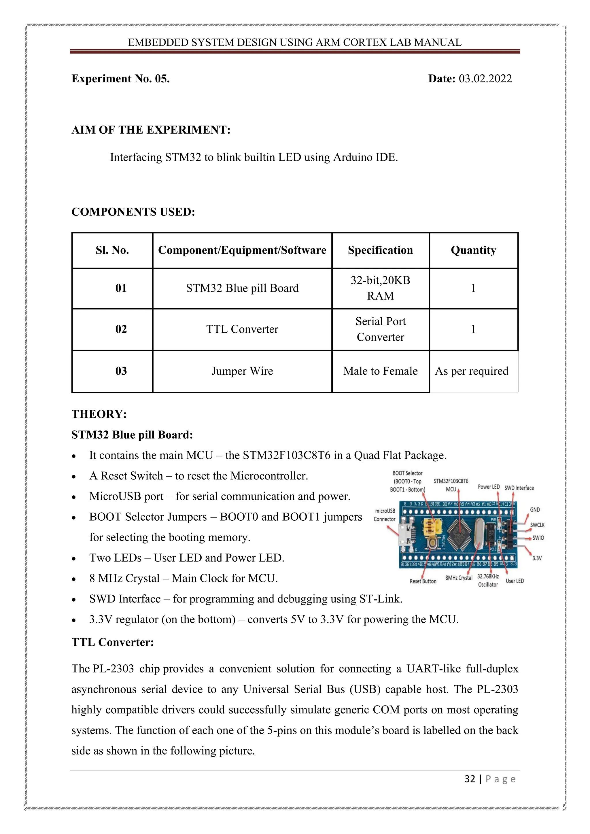


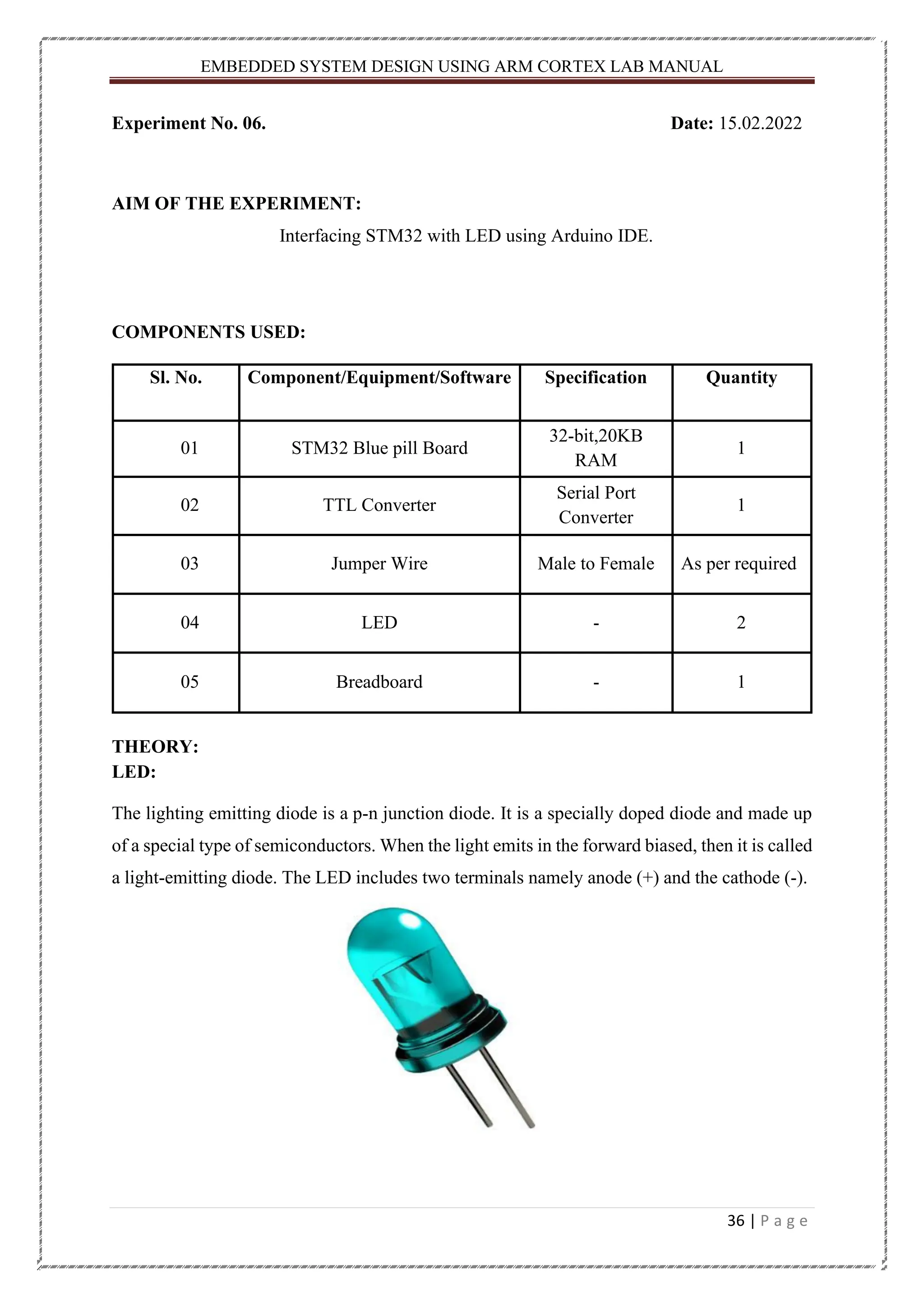
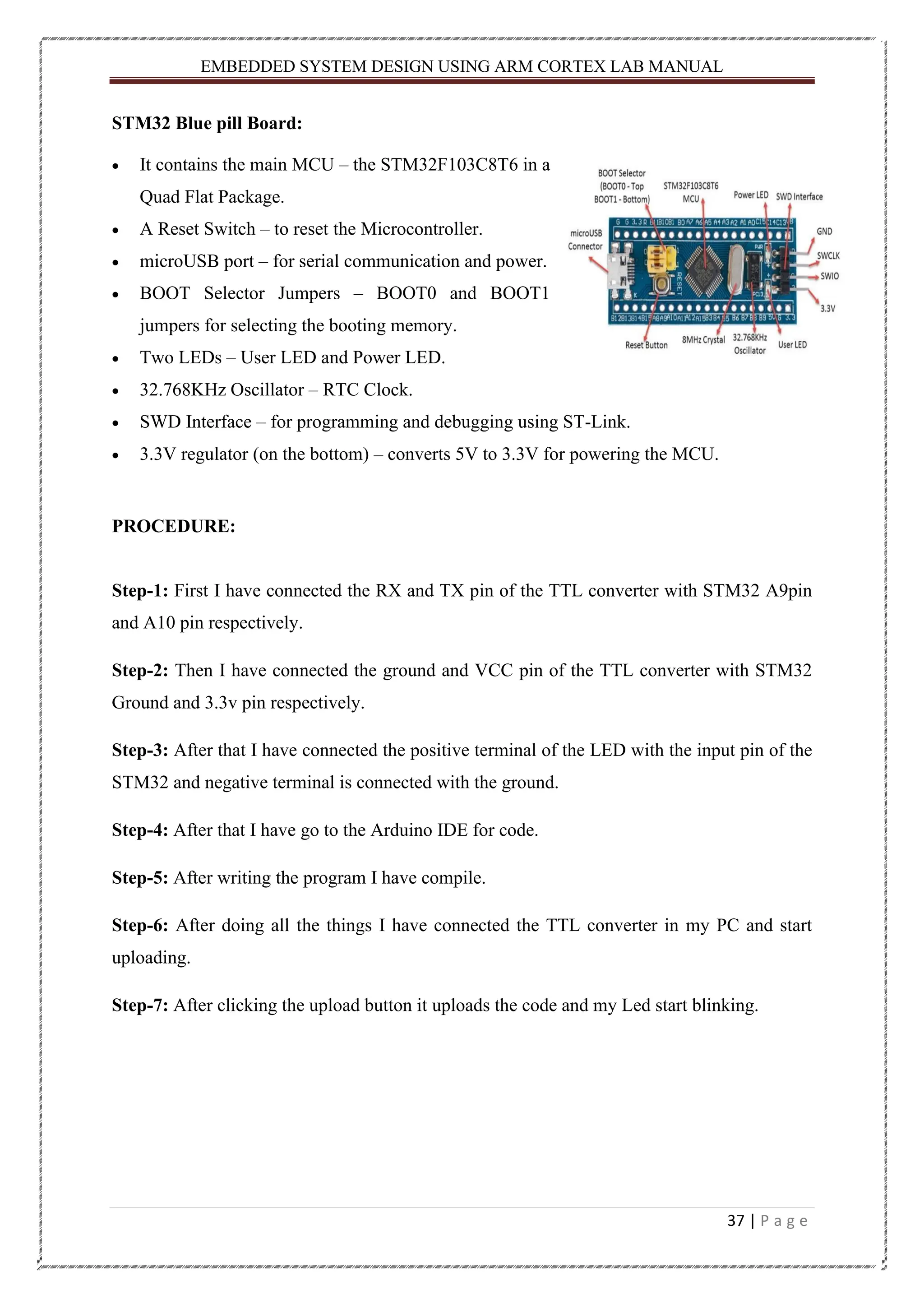

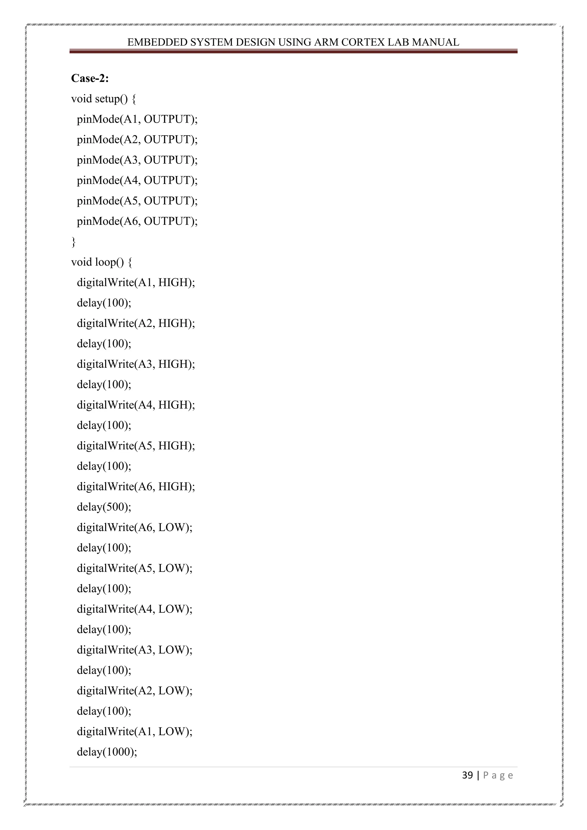
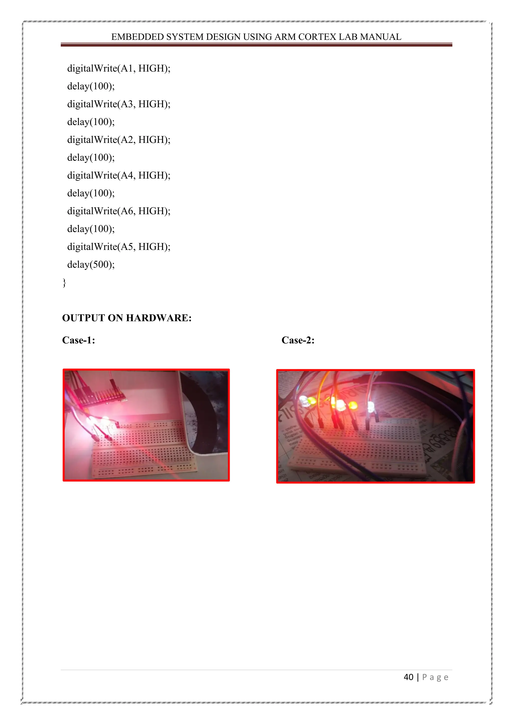

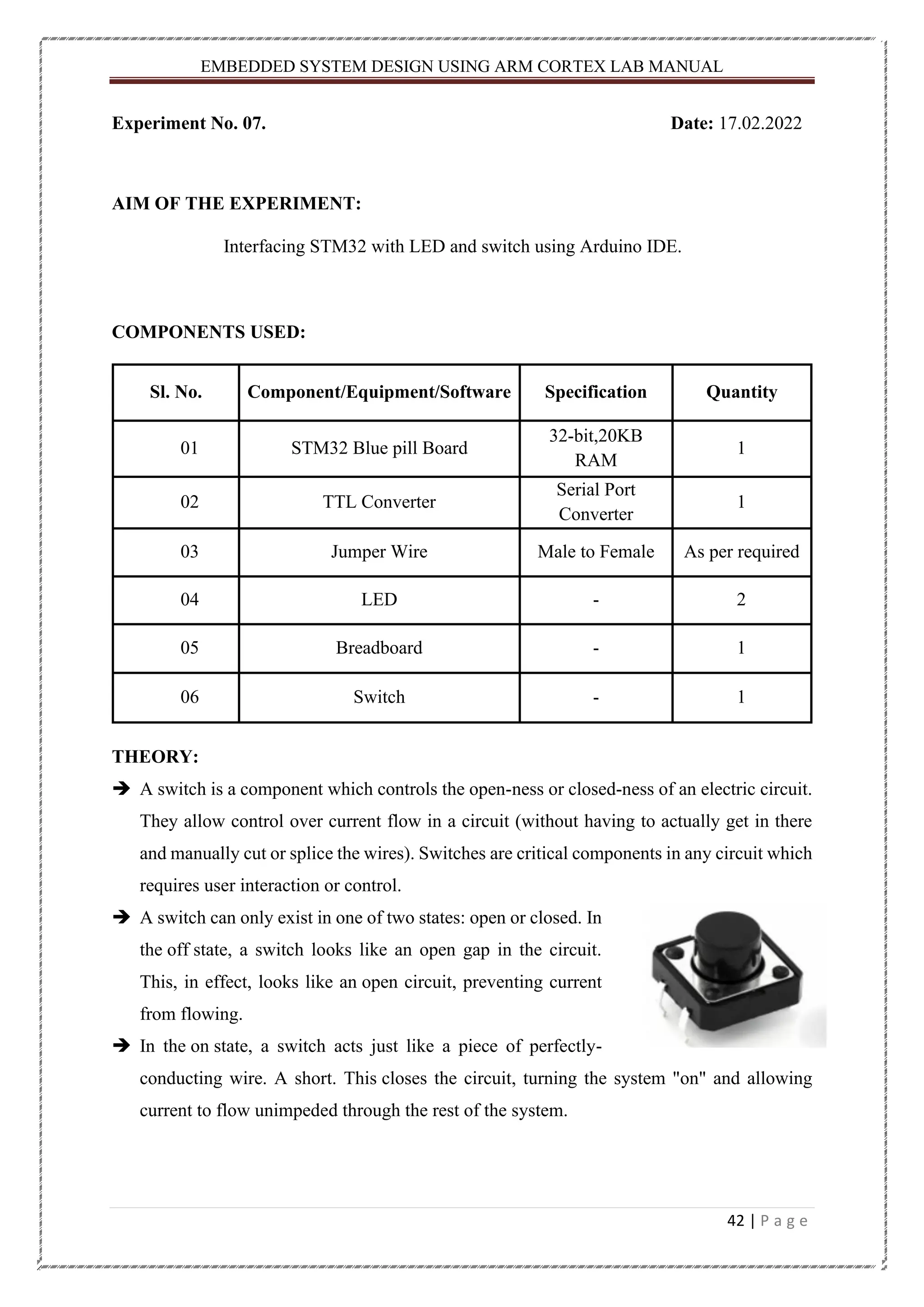


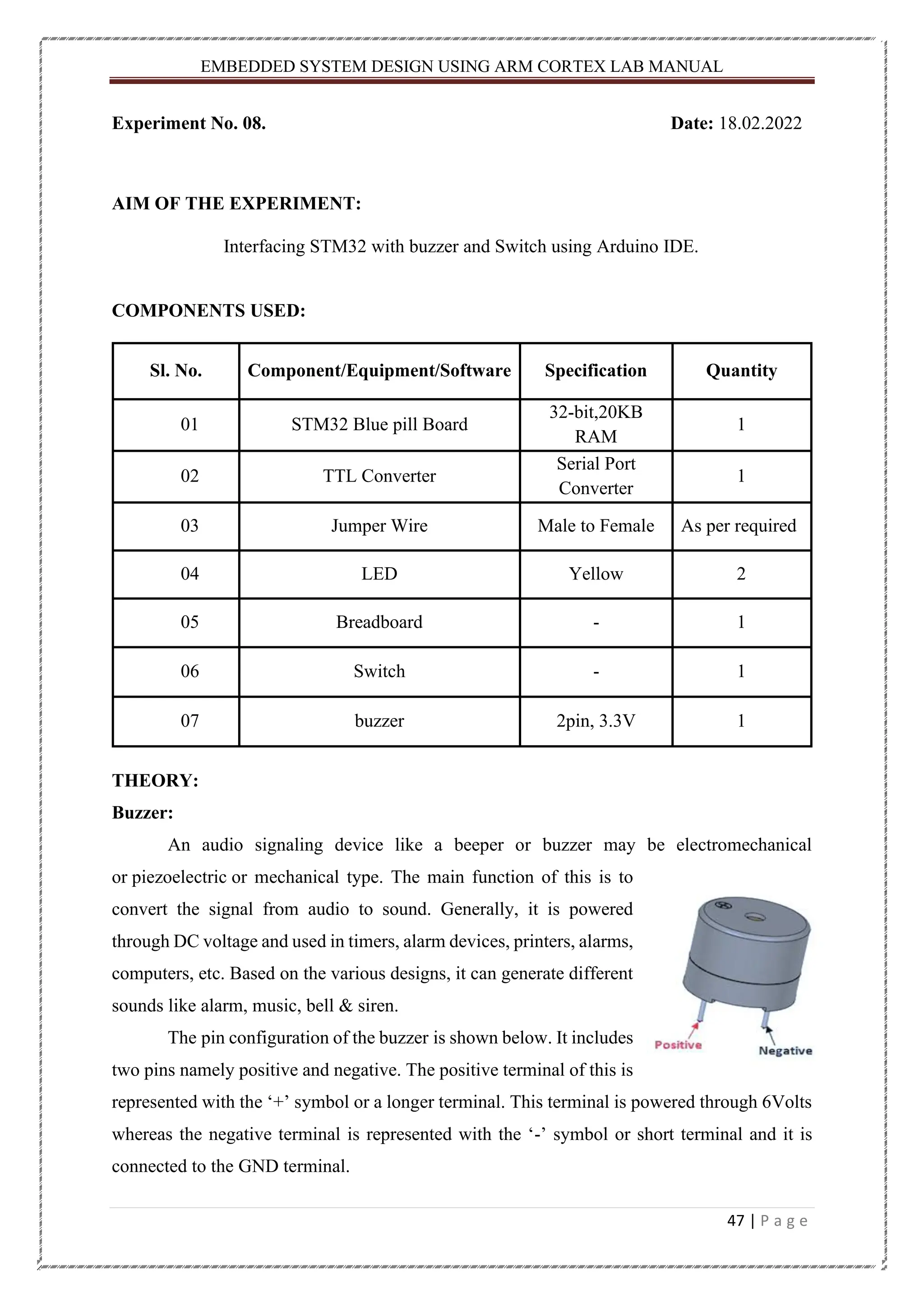
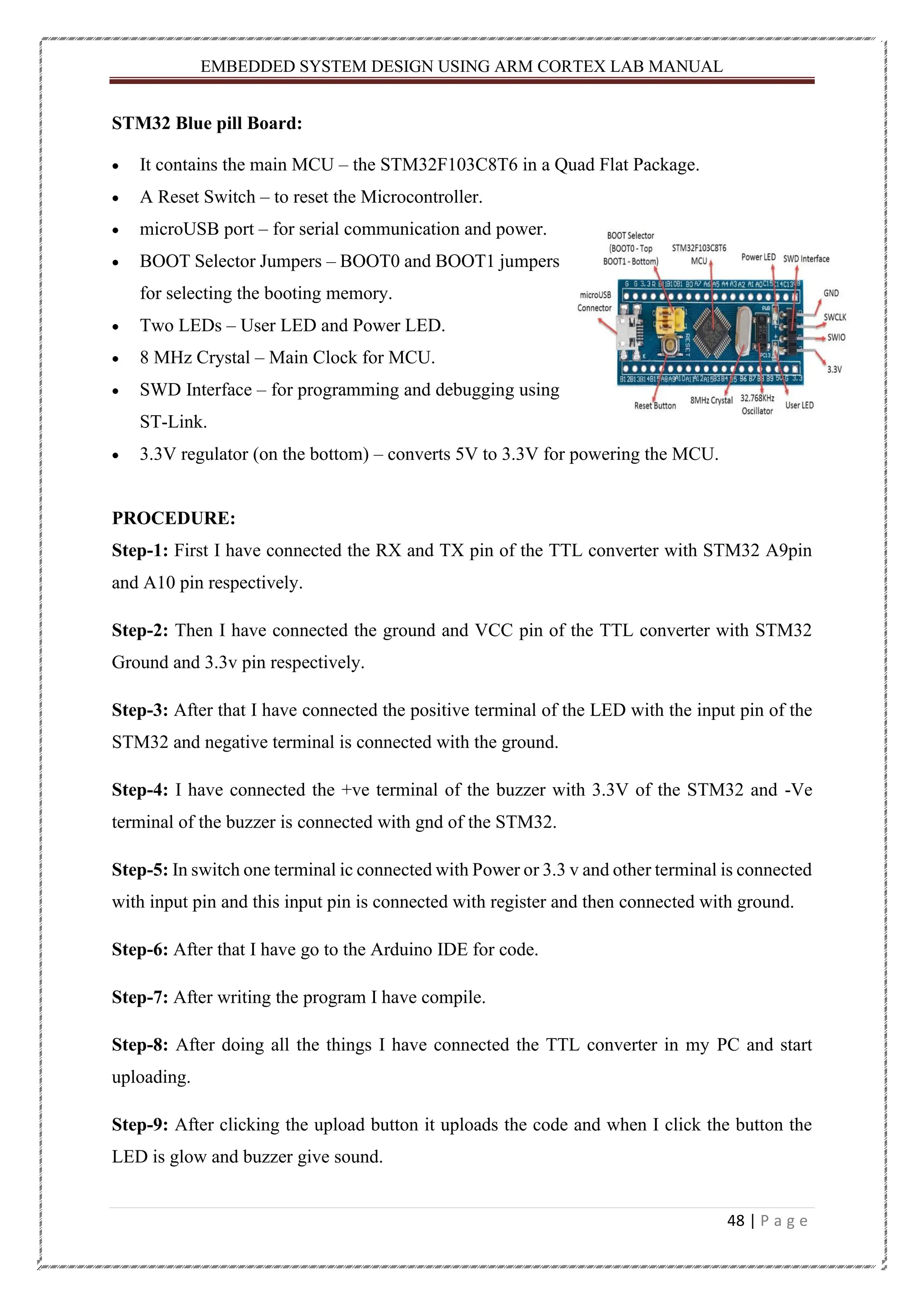


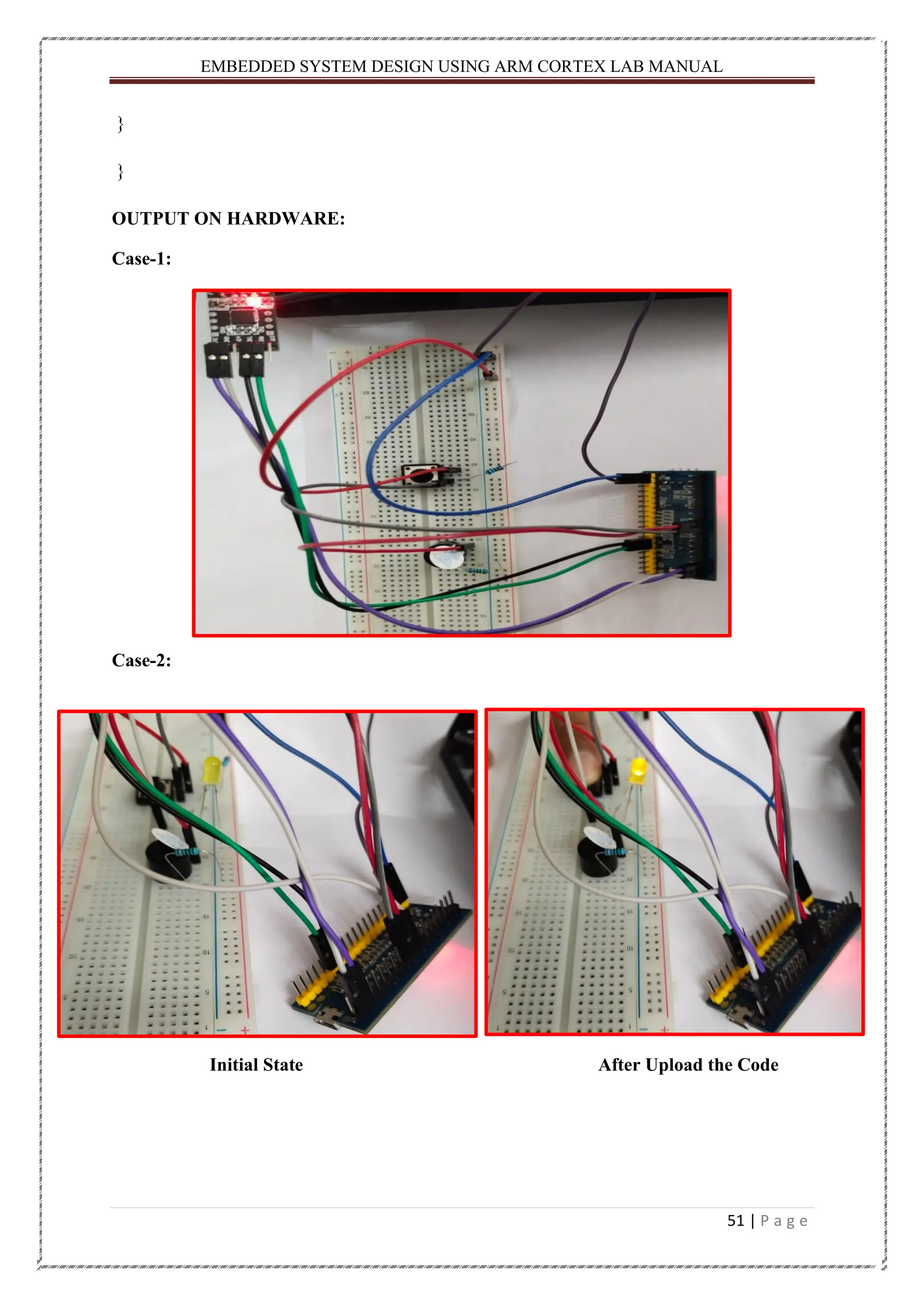

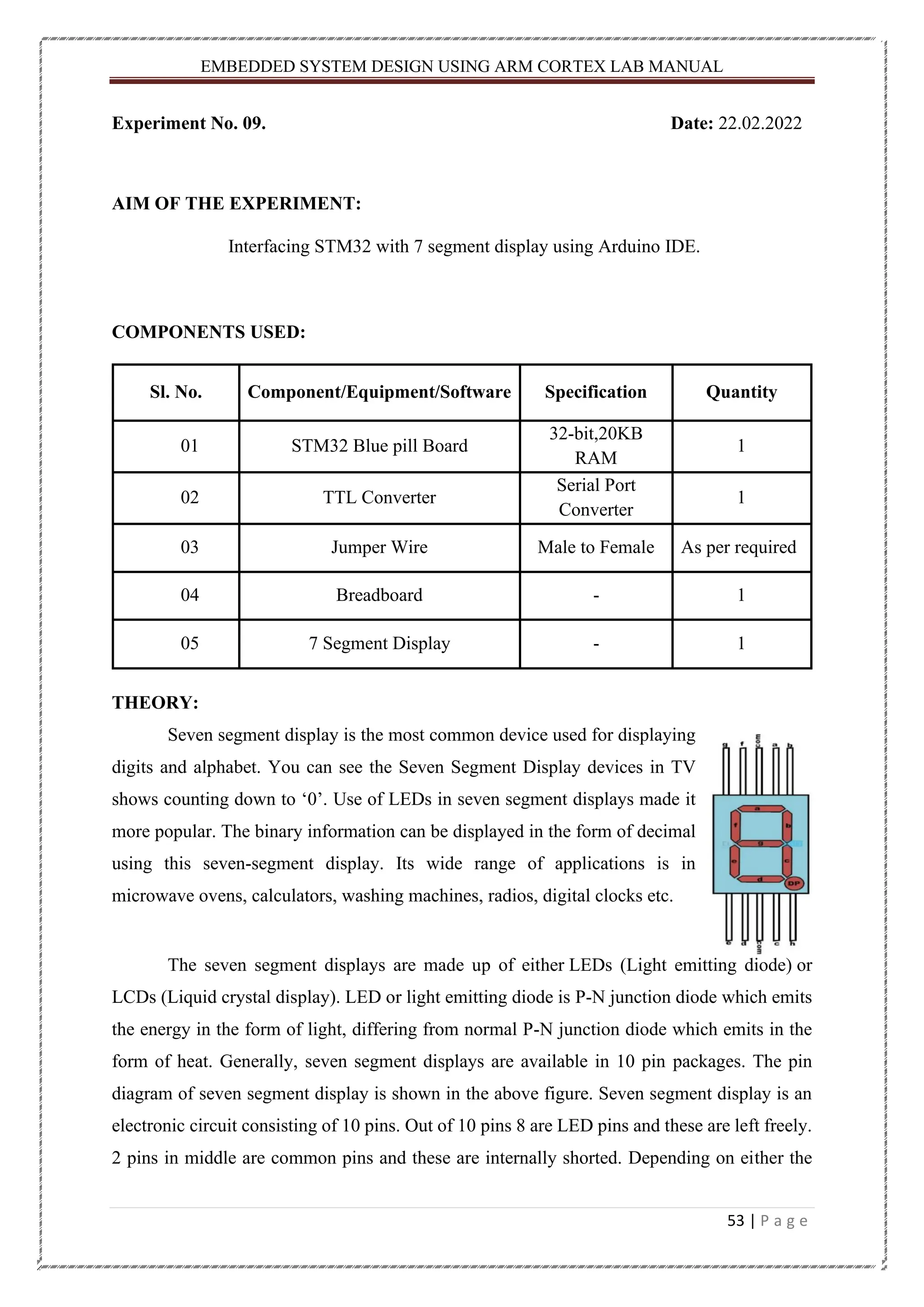
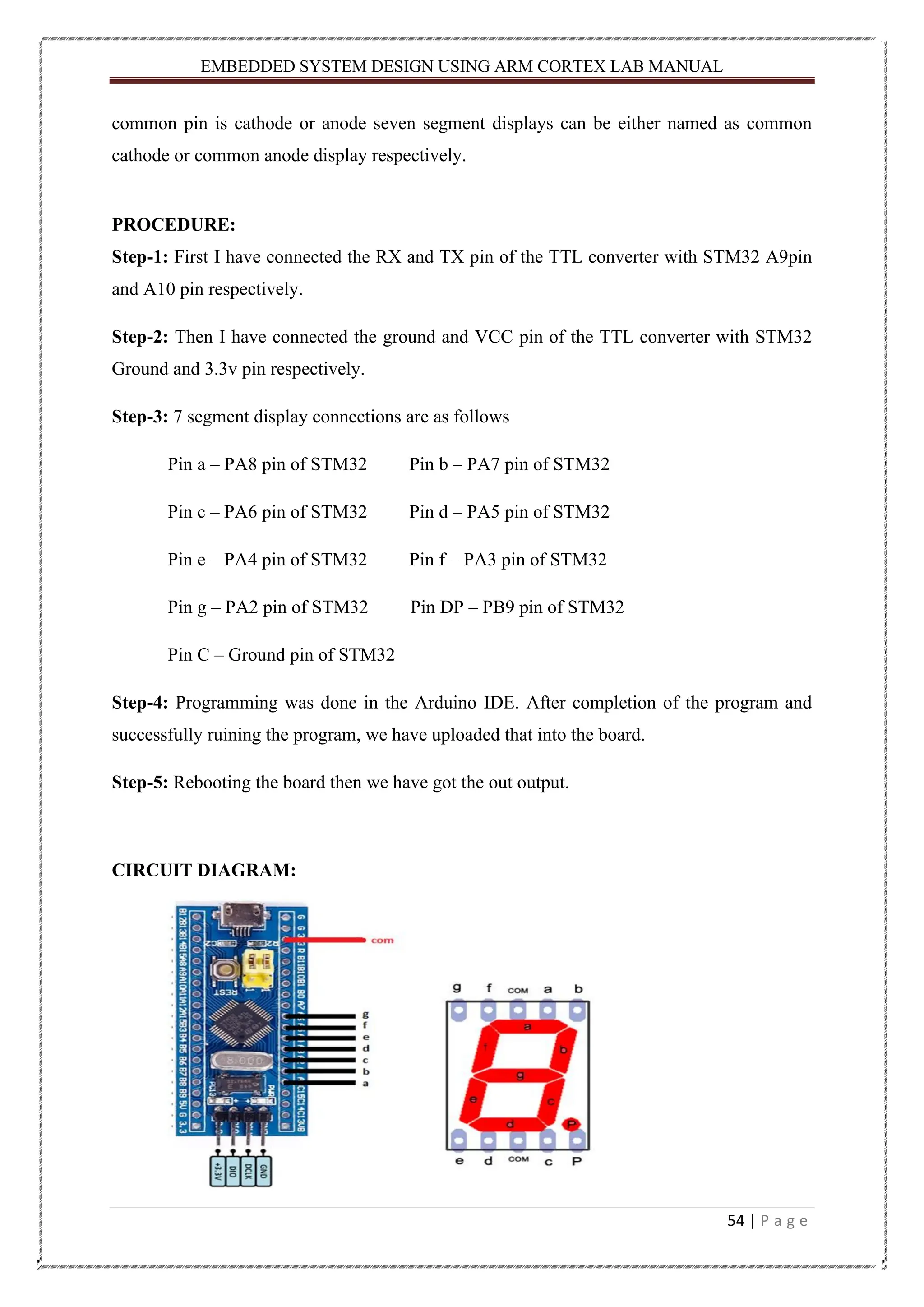
![EMBEDDED SYSTEM DESIGN USING ARM CORTEX LAB MANUAL 55 | P a g e CODE: #define A PA8 #define B PA7 #define C PA6 #define D PA5 #define E PA4 #define F PA3 #define G PA2 #define DP PB9 // decimal #define common_cathode 0 #define common_anode 1 bool segMode = common_cathode; int seg[] {A,B,C,D,E,F,G,DP}; // segment pins byte chars = 35; // max value in the array "Chars" byte Chars[35][9] { {'0',1,1,1,1,1,1,0,0},//0 {'1',0,1,1,0,0,0,0,0},//1 {'2',1,1,0,1,1,0,1,0},//2 {'3',1,1,1,1,0,0,1,0},//3 {'4',0,1,1,0,0,1,1,0},//4 {'5',1,0,1,1,0,1,1,0},//5 {'6',1,0,1,1,1,1,1,0},//6 {'7',1,1,1,0,0,0,0,0},//7 {'8',1,1,1,1,1,1,1,0},//8 {'9',1,1,1,1,0,1,1,0},//9 {'a',1,1,1,0,1,1,1,0},//A/10 {'b',0,0,1,1,1,1,1,0},//b/11 {'c',1,0,0,1,1,1,0,0},//C/12 {'d',0,1,1,1,1,0,1,0},//d/13 {'e',1,0,0,1,1,1,1,0},//E/14 {'f',1,0,0,0,1,1,1,0},//F/15 {'g',1,0,1,1,1,1,0,0},//G/16 {'h',0,1,1,0,1,1,1,0},//H/17](https://image.slidesharecdn.com/embeddedsystemweathermonitoring-231102114604-5047959e/75/Weather-monitoring-System-Using-STM32-55-2048.jpg)
![EMBEDDED SYSTEM DESIGN USING ARM CORTEX LAB MANUAL 56 | P a g e {'i',0,0,0,0,1,1,0,0},//I/18 {'j',0,1,1,1,1,0,0,0},//J/19 {'l',0,0,0,1,1,1,0,0},//L/20 {'n',0,0,1,0,1,0,1,0},//n/21 {'o',0,0,1,1,1,0,1,0},//o/22 {'p',1,1,0,0,1,1,1,0},//P/23 {'q',1,1,1,0,0,1,1,0},//q/24 {'r',0,0,0,0,1,0,1,0},//r/25 {'s',1,0,1,1,0,1,1,0},//S/26 looks like number 5 {'t',0,0,0,1,1,1,1,0},//t/27 {'u',0,1,1,1,1,1,0,0},//U/28 {'y',0,1,1,1,0,1,1,0},//y/29 {'-',0,0,0,0,0,0,1,0},//-/30 {'.',0,0,0,0,0,0,0,1},//./31 {']',1,1,1,1,0,0,0,0},//]/32 {'[',1,0,0,1,1,1,0,0},//[/33 {'_',0,0,0,1,0,0,0,0},//_/34 }; void setup() { pinMode(seg[0],OUTPUT); pinMode(seg[1],OUTPUT); pinMode(seg[2],OUTPUT); pinMode(seg[3],OUTPUT); pinMode(seg[4],OUTPUT); pinMode(seg[5],OUTPUT); pinMode(seg[6],OUTPUT); pinMode(seg[7],OUTPUT); } void setState(bool mode) //sets the hole segment state to "mode" { for(int i = 0;i<=6;i++) { digitalWrite(seg[i],mode); } }](https://image.slidesharecdn.com/embeddedsystemweathermonitoring-231102114604-5047959e/75/Weather-monitoring-System-Using-STM32-56-2048.jpg)
![EMBEDDED SYSTEM DESIGN USING ARM CORTEX LAB MANUAL 57 | P a g e void Print(char Char) { int charNum = -1;// set search resault to -1 setState(segMode);//turn off the segment for(int i = 0; i < chars ;i++){//search for the enterd character if(Char == Chars[i][0]){//if the character found charNum = i; } } if(charNum == -1 )// if the character not found { for(int i = 0;i <= 6;i++) { digitalWrite(seg[i],HIGH); delay(100); digitalWrite(seg[i],LOW); } for(int i = 0;i <= 2;i++) { delay(100); setState(HIGH); delay(100); setState(LOW); } }else // else if the character found print it { for(int i = 0;i<8;i++) {digitalWrite(seg[i],Chars[charNum][i+1]); } } } void Print(int num) // print any number on the segment { setState(segMode);//turn off the segment](https://image.slidesharecdn.com/embeddedsystemweathermonitoring-231102114604-5047959e/75/Weather-monitoring-System-Using-STM32-57-2048.jpg)
![EMBEDDED SYSTEM DESIGN USING ARM CORTEX LAB MANUAL 58 | P a g e if(num > chars || num < 0 )// if the number is not declared { for(int i = 0;i <= 6;i++) { digitalWrite(seg[i],HIGH); delay(100); digitalWrite(seg[i],LOW); } for(int i = 0;i <= 2;i++) { delay(100); setState(HIGH); delay(100); setState(LOW); } }else // else if the number declared, print it { if(segMode == 0){ //for segment mode for(int i = 0;i<8;i++) { digitalWrite(seg[i],Chars[num][i+1]); } } else{ for(int i = 0;i<8;i++) { digitalWrite(seg[i],!Chars[num][i+1]); }} }} void loop() { for(int i = 0;i < chars;i++) //print { Print(i); delay(1000); } }](https://image.slidesharecdn.com/embeddedsystemweathermonitoring-231102114604-5047959e/75/Weather-monitoring-System-Using-STM32-58-2048.jpg)


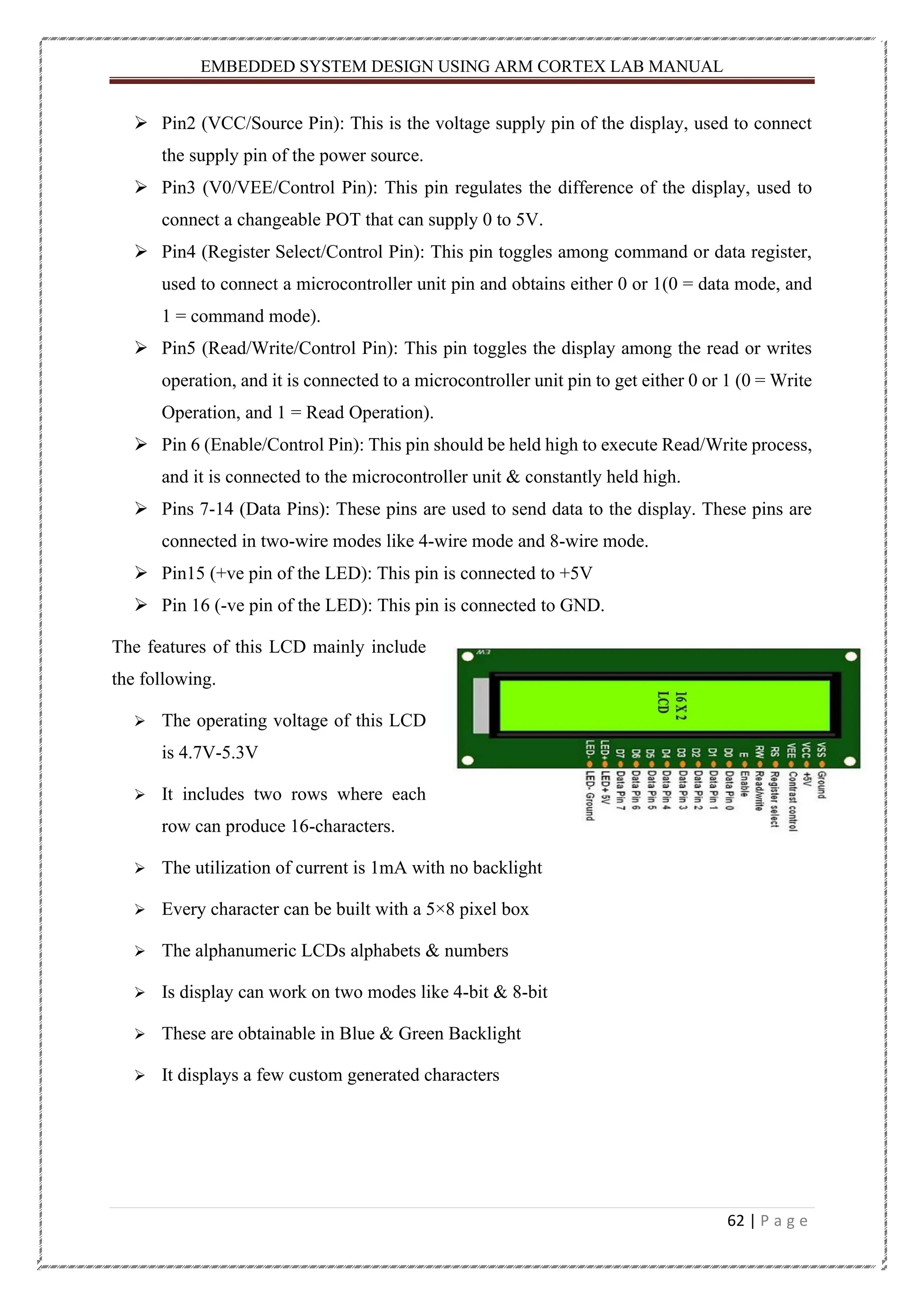
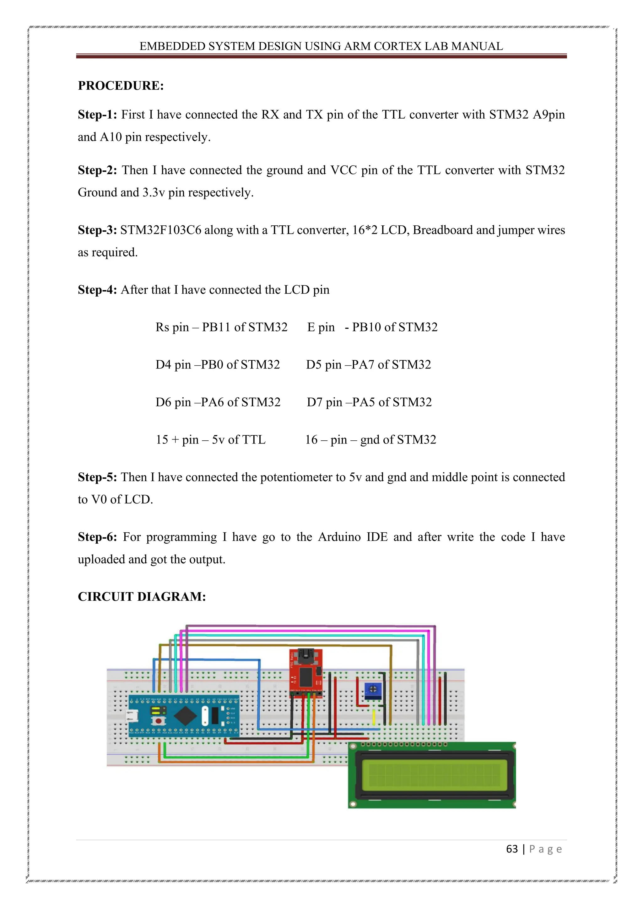


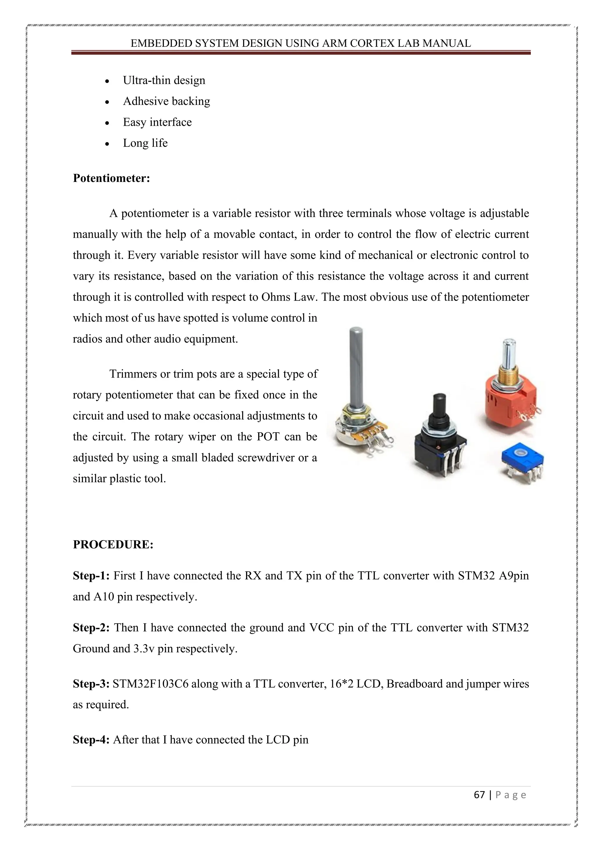

![EMBEDDED SYSTEM DESIGN USING ARM CORTEX LAB MANUAL 69 | P a g e CODE: Case-1: #include <Keypad.h> #include <LiquidCrystal.h> const byte ROWS = 4; //four rows const byte COLS = 4; //four columns //define the cymbols on the buttons of the keypads char hexaKeys[ROWS][COLS] = { {'1','2','3','A'}, {'4','5','6','B'}, {'7','8','9','C'}, {'*','0','#','D'} }; byte rowPins[ROWS] = {PA12, PA15, PB3, PB4}; //connect to the row pinouts of the keypad byte colPins[COLS] = {PB5, PB6, PB7, PB8}; //connect to the column pinouts of the keypad Keypad customKeypad = Keypad( makeKeymap(hexaKeys), rowPins, colPins, ROWS, COLS); LiquidCrystal lcd(PB11, PB10, PA0, PA1, PA2, PA3); void setup() { lcd.begin(16, 2); lcd.print("EMBEDDED SYSTEM"); delay(2000); lcd.clear(); lcd.setCursor(0, 0); } void loop() { char customKey = customKeypad.getKey(); if (customKey) { lcd.print(customKey); }}](https://image.slidesharecdn.com/embeddedsystemweathermonitoring-231102114604-5047959e/75/Weather-monitoring-System-Using-STM32-69-2048.jpg)
![EMBEDDED SYSTEM DESIGN USING ARM CORTEX LAB MANUAL 70 | P a g e Case-2: #include <Keypad.h> #include <Keypad.h> const byte ROWS = 4; const byte COLS = 4; char keys[ROWS][COLS] = { {'1', '2', '3', 'A'}, {'4', '5', '6', 'B'}, {'7', '8', '9', 'C'}, {'*', '0', '#', 'D'} }; byte rowPins[ROWS] = { PA7, PA6, PA5,PA4 }; byte colPins[COLS] = { PA3, PA2, PA1 , PA0}; Keypad kpd = Keypad( makeKeymap(keys), rowPins, colPins, ROWS, COLS );// Create the Keypad #define ledpin PB5 #define ledpin1 PB4 #define ledpin2 PB3 void setup() { pinMode(ledpin, OUTPUT); pinMode(ledpin1, OUTPUT); pinMode(ledpin2, OUTPUT); Serial.begin(9600); } void loop() { char key = kpd.getKey(); if (key=='1') { digitalWrite(ledpin,HIGH);](https://image.slidesharecdn.com/embeddedsystemweathermonitoring-231102114604-5047959e/75/Weather-monitoring-System-Using-STM32-70-2048.jpg)