DECLARATION Ms. G.Yamini bearing HT NO. 101319862022,here by declare that this project entitled “SMART TRAFFIC CONTROL SYSTEM USING CANNY EDGE DETECTION ALGORITHM”submitted to the Department of Computer Science,University Of College For Women, Koti, Hyderabad, in partial fulfillment for the award of Degree of MCA is entirely original and has not been submitted earlier by anyone for degree or diploma. No part of the project work is copied from books/journal/internet and whenever referred the same has been duly acknowledge in the text. The reported data are based on the project work done entirely by me and not copied from any other source. G.Yamini Signature of the Student Date
UNIVERSITY OF COLLEGE FOR WOMEN (Autonomous) Koti, Hyderabad, Telangana state- 500 095 (Constituent College of Osmania University) CPE status & NAAC Re- Accredited – ‘A’ grade /UCW/ /20 Date : CERTIFICATE This is to certify that the project work entitled “ SMART TRAFFIC CONTROL SYSTEM USING CANNY EDGE DETECTION ALGORITHM” submitted by G.YAMINI, (MCA) bearing H.NO : 101319862022 is a bonofide work carried out by her under the guidance of Mrs. SAVITHA REDDY, Assistant professor, Department of Computer Science, University College For Women(Autonomous), Koti, Hyderabad during the Academic year 2021-2022. INTERNAL GUIDE EXTERNAL EXAMINER HEAD OF THE DEPARTMENT PRINCIPAL
A PROJECT REPORT ON SMART TRAFFIC CONTROL SYSTEM USING CANNY EDGE DETECTION ALGORITHM SUBMITTED IN PARTIAL FULFILMENT OF THE REQUIREMENT For the Award of Degree of MASTER OF COMPUTER APPLICATION (MCA) BY GOUDICHARLA YAMINI (HT.NO:101319862022) Under the Esteemed Guidance of Mrs. SAVITHA REDDY Assistant Professor(C), Department of CS, UCW DEPARTMENT OF COMPUTER SCIENCE UNIVERSITY OF COLLEGE FOR WOMEN(A) Osmaniauniversity,Hyderabad-500 095 2022
ACKNOWLEDGEMENT This report is the embodiment of the efforts of several people to whom I would like to express my gratitude. I profoundly thank Prof. M.VIJJU LATHA, Principal, University College for Women, Koti, Hyderabad for her continuous support I profoundly thank Dr. B.SHAILAJA, Vice Principal UCW, for the support provided I sincerely thank our Head of the Department Prof. K.KRISHNA CHAITANYA for her support during the project I sincerely thank our internal guide Mrs. SAVITHA REDDY, Assistant Professor for her continuous guidance and support during the completion of my project I would like to thank the ALMIGHTY, who gave me enough strength and health to complete my project without any interruption Last but not least, I thank all my family members and friends who are my source of encouragement through which I was able to complete the project work effectively and efficiently G.YAMINI 101319862022
ABSTRACT In this paper author is describing concept to control or automate green traffic signal allotment time based on congestion available at road side using Canny Edge Detection Algorithm. To implement this technique we are uploading current traffic image to the application and application will extract edges from images and if there is more traffic then there will be more number of edges with white colour and if uploaded image contains less traffic then it will have less number of white colour edges. Empty edges will have black colour with value 0. By counting number of non-zeroes white pixels we will have complete idea of available traffic and based on that we will allocate time to green signal. If less traffic is there then green signal time will be less otherwise green signal allocation time will be more.
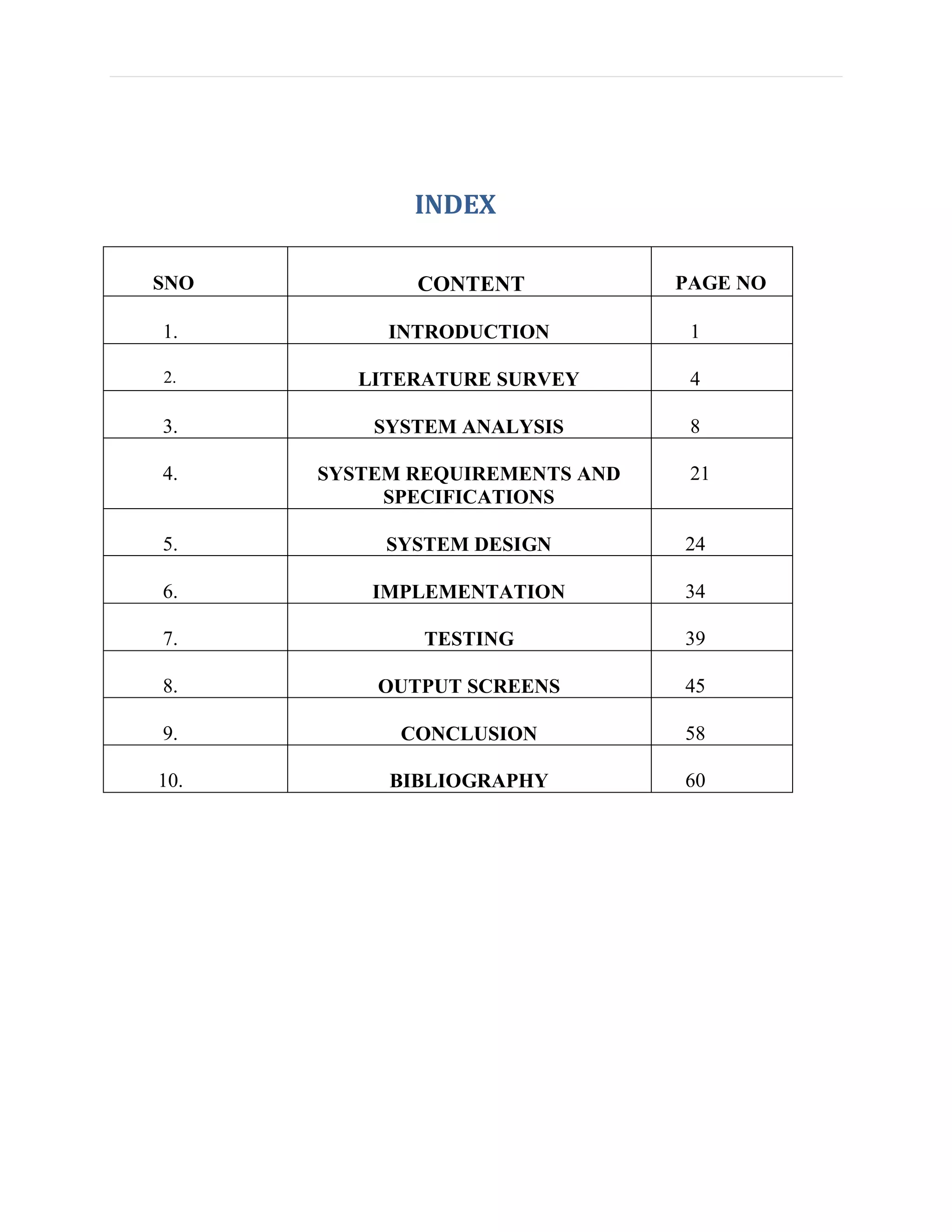
INDEX SNO CONTENT PAGE NO 1. INTRODUCTION 1 2. LITERATURE SURVEY 4 3. SYSTEM ANALYSIS 8 4. SYSTEM REQUIREMENTS AND SPECIFICATIONS 21 5. SYSTEM DESIGN 24 6. IMPLEMENTATION 34 7. TESTING 39 8. OUTPUT SCREENS 45 9. CONCLUSION 58 10. BIBLIOGRAPHY 60
LIST OF CONTENTS SNO CONTENTS Page no 1. INTRODUCTION 1-3 2. LITERATURE SURVEY 4-7 3. SYSTEM ANALYSIS  EXISTING SYSTEM  DRAWBACKS  PROPOSED SYSTEM  ADVANTAGES  MODULES DESCRIPTION  FEASIBILITY STUDY  ECONOMIC FEASIBILITY  OPERATIONAL FEASIBILIY  TECHNICAL FEASIBILITY 8-20 4. SYSTEM REQUIREMENTS AND SPECIFICATIONS  HARDWARE REQUIREMENTS  SOFTWARE REQUIREMENTS 21-23 5. SYSTEM DESIGN  INTRODUCTION  UML DIAGRAMS  DATA DESIGN 24-33 6. IMPLEMENTATION  CODING 34-38
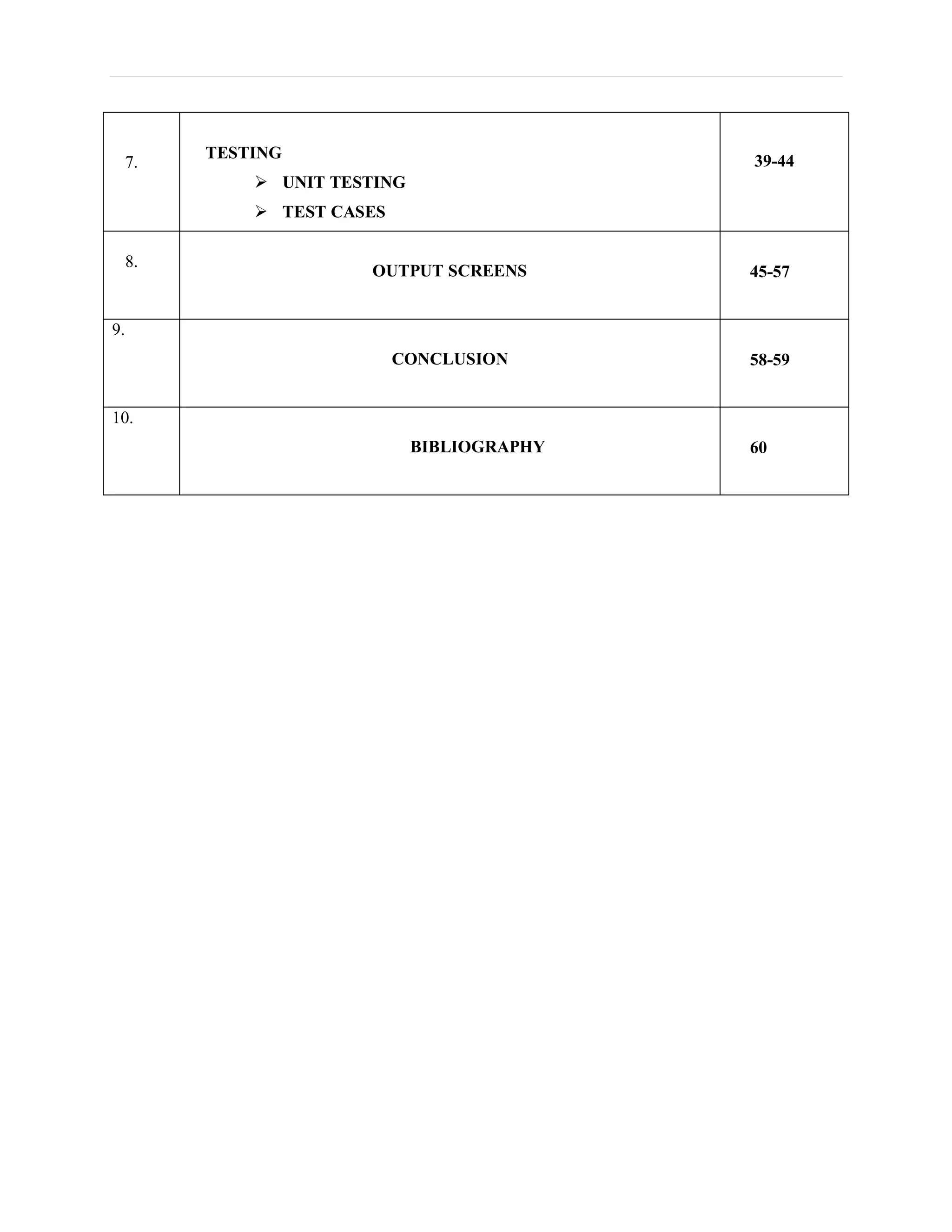
7. TESTING  UNIT TESTING  TEST CASES 39-44 8. OUTPUT SCREENS 45-57 9. CONCLUSION 58-59 10. BIBLIOGRAPHY 60
1. INTRODUCTION  Purpose  Scope of the Project  Objectives of the Project
P a g e | 1 1.INTRODUCTION : • Traffic congestion is one of the major modern-day crisis in every big city in the world. Recent study of World Bank has shown that average vehicle speed has been reduced from 21 km to 7 km per hour in the last 10 years in Dhaka. • Inter metropolitan area studies suggest that traffic congestion reduces regional competitiveness and redistributes economic activity by slowing growth in county gross output or slowing metropolitan area employment growth. • As more and more vehicles are commissioning in an already congested traffic system, there is an urgent need for a whole new traffic control system using advanced technologies to utilize the already existent infrastructures to its full extent. • Since building new roads, flyovers, elevated expressway etc. needs extensive planning, huge capital and lots of time; focus should be directed upon availing existing infrastructures more efficiently and diligently. • Some of them count total number of pixels , some of the work calculate number of vehicles. These methods have shown promising results in collecting traffic data. • However, calculating the number of vehicles may give false results if the intra vehicular spacing is very small (two vehicles close to each other may be counted as one) and it may not count rickshaw or auto-rickshaw as vehicles which are the quotidian means of traffic especially in South-Asian countries. • And counting number of pixels has disadvantage of counting insubstantial materials as vehicles such as footpath or pedestrians. Some of the work have proposed to allocate time based solely on the density of traffic. But this may be disadvantageous for those who are in lanes that have less frequency of traffic.
P a g e | 2 1.1 Scope for future work : The focus shall be to implement the controller using DSP as it can avoid heavy investment in industrial control computer while obtaining improved computational power and optimized system structure. The hardware implementation would enable the project to be used in real-time practical conditions. In addition, we propose a system to identify the vehicles as they pass by, giving preference to emergency vehicles and assisting in surveillance on a large scale.
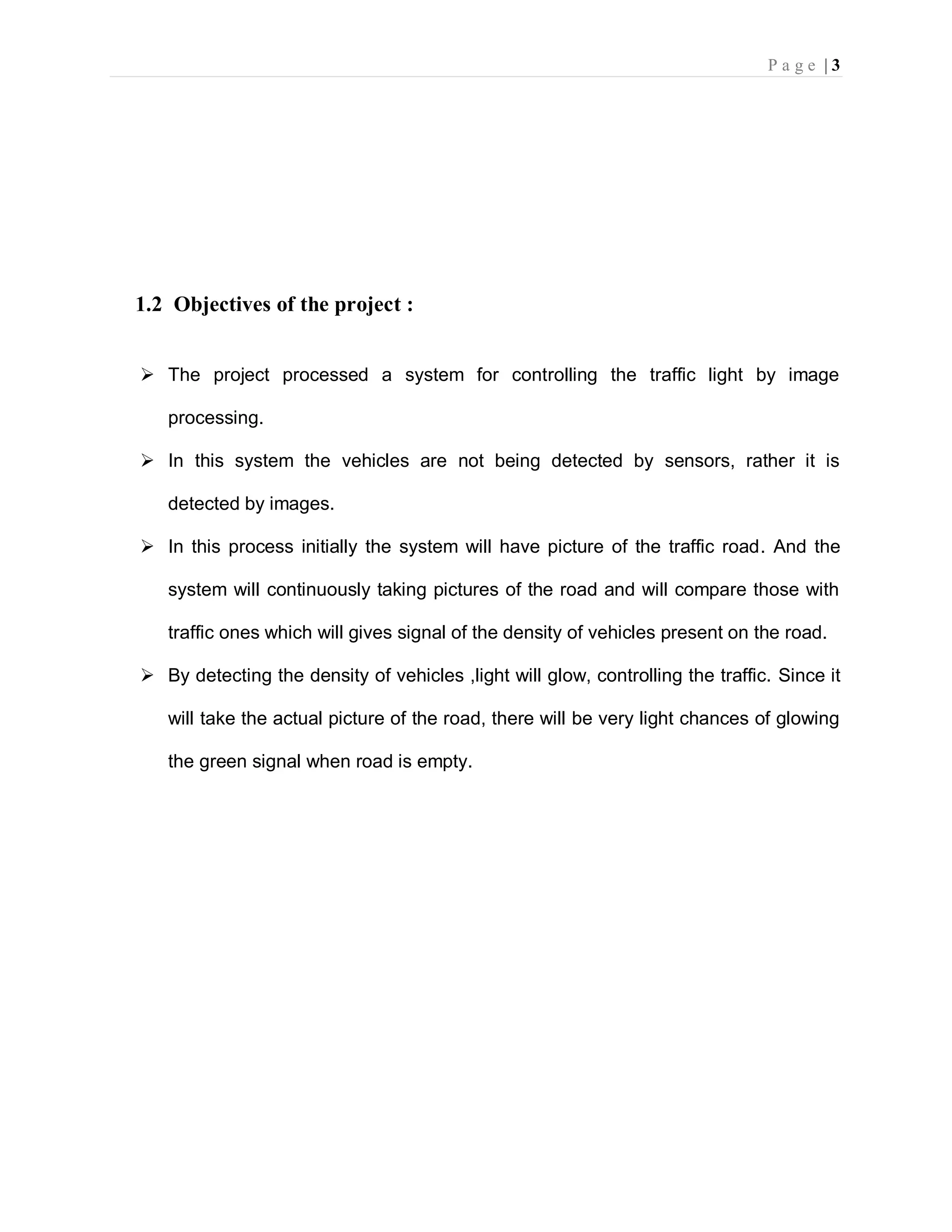
P a g e | 3 1.2 Objectives of the project :  The project processed a system for controlling the traffic light by image processing.  In this system the vehicles are not being detected by sensors, rather it is detected by images.  In this process initially the system will have picture of the traffic road. And the system will continuously taking pictures of the road and will compare those with traffic ones which will gives signal of the density of vehicles present on the road.  By detecting the density of vehicles ,light will glow, controlling the traffic. Since it will take the actual picture of the road, there will be very light chances of glowing the green signal when road is empty.
P a g e | 4 2. Literature Survey
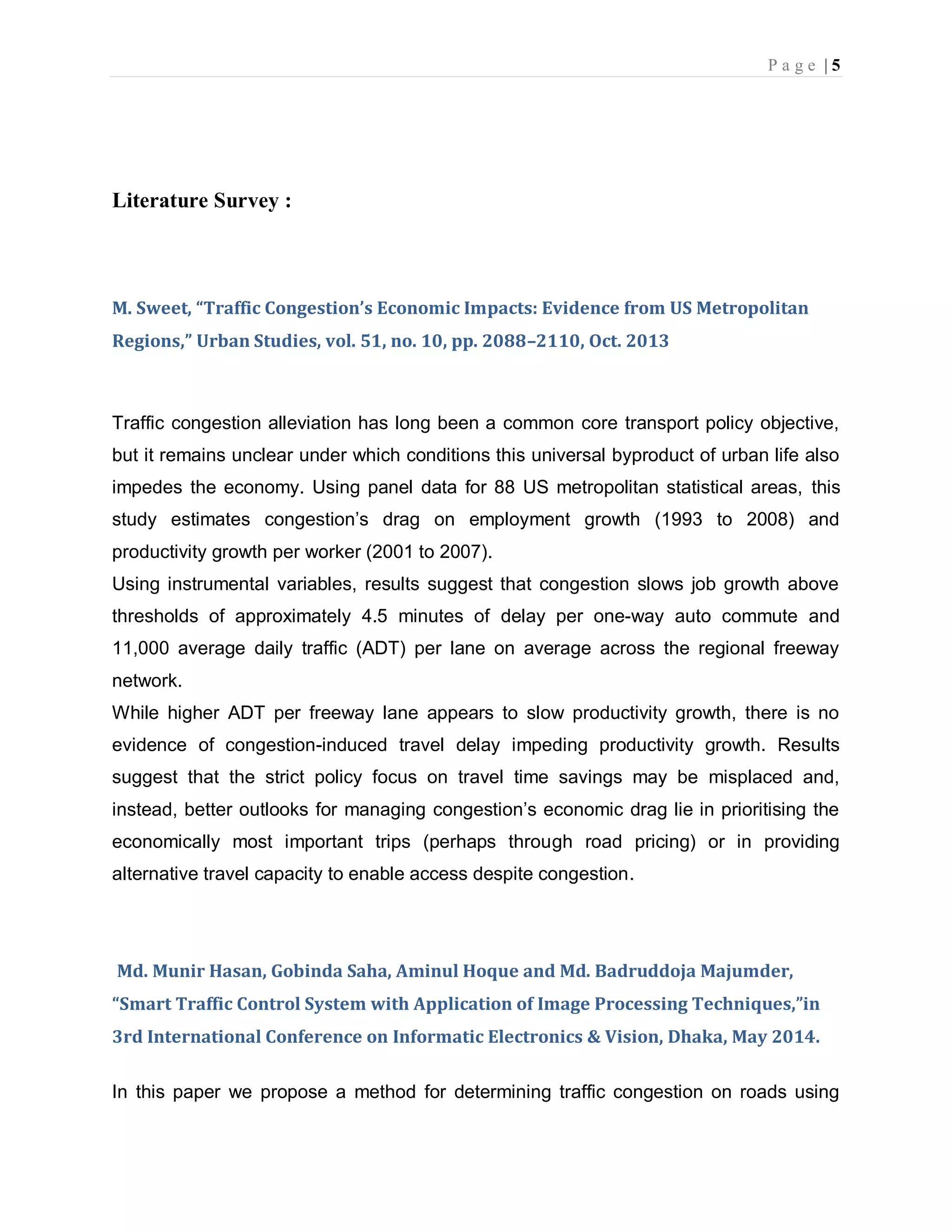
P a g e | 5 Literature Survey : M. Sweet, “Traffic Congestion’s Economic Impacts: Evidence from US Metropolitan Regions,” Urban Studies, vol. 51, no. 10, pp. 2088–2110, Oct. 2013 Traffic congestion alleviation has long been a common core transport policy objective, but it remains unclear under which conditions this universal byproduct of urban life also impedes the economy. Using panel data for 88 US metropolitan statistical areas, this study estimates congestion’s drag on employment growth (1993 to 2008) and productivity growth per worker (2001 to 2007). Using instrumental variables, results suggest that congestion slows job growth above thresholds of approximately 4.5 minutes of delay per one-way auto commute and 11,000 average daily traffic (ADT) per lane on average across the regional freeway network. While higher ADT per freeway lane appears to slow productivity growth, there is no evidence of congestion-induced travel delay impeding productivity growth. Results suggest that the strict policy focus on travel time savings may be misplaced and, instead, better outlooks for managing congestion’s economic drag lie in prioritising the economically most important trips (perhaps through road pricing) or in providing alternative travel capacity to enable access despite congestion. Md. Munir Hasan, Gobinda Saha, Aminul Hoque and Md. Badruddoja Majumder, “Smart Traffic Control System with Application of Image Processing Techniques,”in 3rd International Conference on Informatic Electronics & Vision, Dhaka, May 2014. In this paper we propose a method for determining traffic congestion on roads using
P a g e | 6 image processing techniques and a model for controlling traffic signals based on information received from images of roads taken by video camera. We extract traffic density which corresponds to total area occupied by vehicles on the road in terms of total amount of pixels in a video frame instead of calculating number of vehicles. We set two parameters as output, variable traffic cycle and weighted time for each road based on traffic density and control traffic lights in a sequential manner. Vismay Pandit, Jinesh Doshi, Dhruv Mehta, Ashay Mhatre and Abhilash Janardhan, “Smart Traffic Control System Using Image Processing,”International Journal of Emerging Trends & Technology in Computer Science (IJETTCS), Vol. 3, Issue 1, January – February 2014 In this paper we propose a method for determining traffic congestion on roads using image processing techniques and a model for controlling traffic signals based on information received from images of roads taken by video camera. We extract traffic density which corresponds to total area occupied by vehicles on the road in terms of total amount of pixels in a video frame instead of calculating number of vehicles. We set two parameters as output, variable traffic cycle and weighted time for each road based on traffic density and control traffic lights in a sequential manner. Pallavi Choudekar, Sayanti Banerjee and M. K. Muju, “Implementation of image processing in real time traffic light control,” in3rd International Conference on Electronics Computer Technology, April, 2011. In this paper we propose a method for determining traffic congestion on roads using image processing techniques and a model for controlling traffic signals based on
P a g e | 7 information received from images of roads taken by video camera. We extract traffic density which corresponds to total area occupied by vehicles on the road in terms of total amount of pixels in a video frame instead of calculating number of vehicles. We set two parameters as output, variable traffic cycle and weighted time for each road based on traffic density and control traffic lights in a sequential manner.
P a g e | 8 3. System analysis  Existing System  Proposed System  Block Diagram  Modules of the Application  System study
P a g e | 9 3. SYSTEM ANALYSIS This chapter provides the details of the existing system and proposed system. 3.1 Existing System :- In present traffic control system it require man power to control the traffic. Depending on the countries and states the traffic polices are allotted for a required area or city to control traffic. The traffic polices will carry sign board, sign light and whistle to control the traffic. They will be instructed to wear specific uniforms in order to control the traffic. Previously different techniques had been proposed, such as infra-red light sensor, induction loop etc. to acquire traffic date which had their fair share of demerits. In recent years, image processing has shown promising outcomes in acquiring real time traffic information using CCTV footage installed along the traffic light. Drawbacks:- In the manual controlling system we need more man power. As we have poor strength of traffic police we cannot control traffic manually in all area of a city or town. So we need a better solution to control the traffic. On the other side, automatic traffic controlling a traffic light uses timer for every phase. Using electronic sensors is another way in order to detect vehicles, and produce signal that to this method the time is being wasted by a green light on an empty road. Traffic congestion also occurred while using the electronic sensors for controlling the traffic. All these drawbacks are supposed to be eliminated by using image processing.
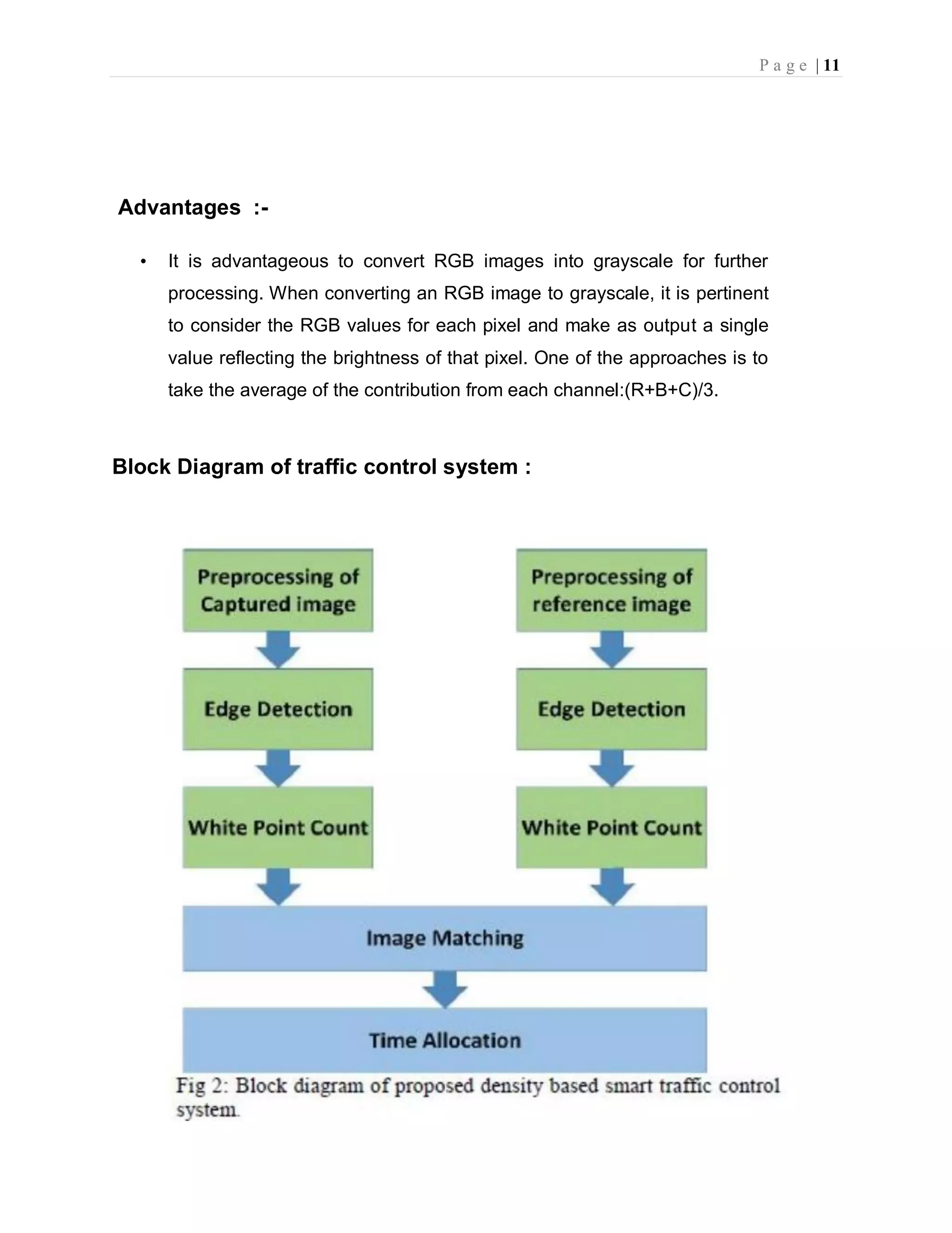
P a g e | 10 3.2 Proposed System :-  To implement this technique we are uploading current traffic image to the application and application will extract edges from images and if there is more traffic then there will be more number of edges with white colour and if uploaded image contains less traffic then it will have less number of white colour edges.  In this paper, a system in which density of traffic is measured by comparing captured image with real time traffic information against the image of the empty road as reference image is proposed. Here, in figure 1, the block diagram for proposed traffic control technique is illustrated.  Each lane will have a minimum amount of green signal duration allocated. According to the percentage of matching allocated traffic light duration can be controlled. The matching is achieved by comparing the number of white points between two images.  The entire image processing before edge detection i.e. image acquisition, image resizing, RGB to gray conversion and noise reduction. After that, canny edge detection operation and white point count are depicted. Canny edge detector operator is selected because of its greater overall performance.
P a g e | 11 Advantages :- • It is advantageous to convert RGB images into grayscale for further processing. When converting an RGB image to grayscale, it is pertinent to consider the RGB values for each pixel and make as output a single value reflecting the brightness of that pixel. One of the approaches is to take the average of the contribution from each channel:(R+B+C)/3. Block Diagram of traffic control system :
P a g e | 12 1.Image processing : Image processing involves issues related to image representation, compression techniques and various complex operations, which can be carried out on the image data. The operations that come under image processing are image enhancement operations such as sharpening, blurring, brightening, edge enhancement .Traffic density of lanes is calculated using image processing which is done of images of lanes that are captured using digital camera. We have chosen image processing for calculation of traffic density as cameras are very much cheaper than other devices. 2. Image Acquisition : Generally an image is a two-dimensional function f(x,y)(here x and y are plane coordinates).The amplitude of image at any point say f is called intensity of the image. It is also called the gray level of image at that point. We need to convert these x and y values to finite discrete values to form a digital image. The input image is a fundus taken from stare data base and drive data base. The image of the retina is taken for processing and to check the condition of the person. We need to convert the analog image to digital image to process it through digital computer. Each digital image composed of a finite elements and each finite element is called a pixel. 3. Image processing : i. Image Resizing/Scaling : Image scaling occurs in all digital photos at some stage whether this be in Bayer demosaicing or in photo enlargement. It happens anytime you resize your image from one pixel grid to another. Image resizing is necessary when you need to increase or decrease the total number of pixels. Even if the same image resize is performed, the result can vary significantly depending on the algorithm. Images are resized because of number of reasons but one of them is very important in our project. Every camera has
P a g e | 13 its resolution, so when a system is designed for some camera specifications it will not run correctly for any other camera depending on specification similarities. so it is necessary to make the resolution constant for the application. ii. RGB to Gray Conversion : Humans perceive color through wavelength-sensitive sensory cells called cones. There are three different varieties of cones, each has a different sensitivity to electromagnetic radiation (light) of different wavelength. One cone is mainly sensitive to green light, one to red light, and one to blue light. By emitting a restricted combination of these three colors (red, green and blue), and hence stimulate the three types of cones at will, we are able to generate almost any detectable colour. iii. Image Enhancement : Image enhancement is the process of adjusting digital images so that the results are more suitable for display or further analysis. For example, we can eliminate noise, which will make it more easier to identify the key characteristics. In poor contrast images, the adjacent characters merge during binarization. We have to reduce the spread of the characters before applying a threshold to the word image. Hence, we introduce “POWER- LAW TRANSFORMATION” which increases the contrast of the characters and helps in better segmentation. 4. Edge Detection : Edge detection is the name for a set of mathematical methods which aim at identifying points in a digital image at which the image brightness changes sharply or, more technically, has discontinuities or noise. The points at which image brightness alters sharply are typically organized into a set of curved line segments termed edges. The
P a g e | 14 same problem of detecting discontinuities in 1D signal is known as step detection and the problem of finding signal discontinuities over time is known as change detection. Edge detection is a basic tool in image processing, machine vision and computer envisage, particularly in the areas of feature reveal and feature extraction. 4.1 Edge Detection Techniques : Different colours have different brightness values of particular colour. Green image has more bright than red and blue image or blue image is blurred image and red image is the high noise image. Following are list of various edge-detection methods:-  Sobel Edge Detection Technique  Perwitt Edge Detection  Roberts Edge Detection Technique  Zero cross Threshold Edge Detection Technique  Canny Edge Detection Technique In our project we use “CANNY EDGE DETECTION TECHNIQUE” because of its various advantages over other edge detection techniques. 5. Canny Edge Detection : The Canny Edge Detector is one of the most commonly used image processing tools detecting edges in a very robust manner. It is a multi-step process, which can be implemented on the GPU as a sequence of filters. Canny edge detection technique is based on three basic objectives.
P a g e | 15 5.1 Low error rate:- All edges should be found, and there should be no spurious responses. That is, the edges must be as close as possible to the true edges. 5.2 Edge point should be well localized:- The edges located must be as close as possible to the true edges. That is , the distance between a point marked as an edge by the detector and the centre of the true edge should be minimum.
P a g e | 16 5.3 Single edge point response:- The detector should return only one point for each true edge point. That is, the number of local maxima around the true edge should be minimum. This means that the detector should not identify multiple edge pixels where only a single edge point exists. Canny edge detection algorithm consist of the following basic steps: i. Smooth the input image with Gaussian filter. ii. Compute the gradient magnitude and angle images. iii. Apply non-maxima suppression to the gradient magnitude image. iv. Use double thresh holding and connectivity analysis to detect and link edges. 6. Image Matching : Comparing a reference image with the real time image pixel by pixel. Though there are so many disadvantages related to pixel based matching but it is one of the best techniques for the algorithm which is used in the project for decision making. Real image is stored in matric in memory and the real time image is also converted in the desired matric. For images to be same their pixel values in matrix must be same. This is the simplest fact used in pixel matching. If there is any mismatch in pixel value it adds on to the counter used to calculate number of pixel mismatches. Finally percentage of matching is expressed as The block diagram of the proposed algorithm discussed above is implemented in MATLAB R2013a. So it is necessary to gain an insight of MATLAB.
P a g e | 17 Fig : Image Processing
P a g e | 18 3.3 Modules of the Application:  Upload Image Module  Pre Process Module  White pixel count Module Upload Image Module: In this module current traffic image will be uploaded to application and then convert colour image into Gray Scale image format to have pixels values as black and white colour. Pre-process module: In this module Gaussian Filter will be applied on uploaded image to convert image into smooth format. After applying filter Canny Edge Detection will be applied on image to get edges from the image. Each vehicle will have white colour pixels and non-vehicle will have black colour pixels. White Pixel Count Module: Using this module we will count white pixels from canny image to get complete traffic count. Calculate Green Signal Time Allocation Module: Based on white pixel count traffic signal time will be calculated. How this time will be calculated is already explain in previous page.
P a g e | 19 3.4 System Study : Feasibility Study : The feasibility of the project is analyzed in this phase and business proposal is put forth with a very general plan for the project and some cost estimates. During system analysis the feasibility study of the proposed system is to be carried out. This is to ensure that the proposed system is not a burden to the company. For feasibility analysis, some understanding of the major requirements for the system is essential. Three key considerations involved in the feasibility analysis are :  ECONOMICAL FEASIBILITY  TECHNICAL FEASIBILITY  SOCIAL FEASIBILITY 3.4.1 ECONOMICAL FEASIBILITY : This study is carried out to check the economic impact that the system will have on the organization. The amount of fund that the company can pour into the research and development of the system is limited. The expenditures must be justified. Thus the developed system as well within the budget and this was achieved because most of the technologies used are freely available. Only the customized products had to be purchased.
P a g e | 20 3.4.2 TECHNICAL FEASIBILITY : This study is carried out to check the technical feasibility, that is, the technical requirements of the system. Any system developed must not have a high demand on the available technical resources. This will lead to high demands on the available technical resources. This will lead to high demands being placed on the client. The developed system must have a modest requirement, as only minimal or null changes are required for implementing this system. 3.4.3 SOCIAL FEASIBILITY : The aspect of study is to check the level of acceptance of the system by the user. This includes the process of training the user to use the system efficiently. The user must not feel threatened by the system, instead must accept it as a necessity. The level of acceptance by the users solely depends on the methods that are employed to educate the user about the system and to make him familiar with it. His level of confidence must be raised so that he is also able to make some constructive criticism, which is welcomed, as he is the final user of the system.
P a g e | 21 4. System Requirements and Specifications  Hardware Requirements  Software Requirements
P a g e | 22 4. REQUIREMENT ANALYSIS : The project involved analyzing the design of few applications so as to make the application more users friendly. To do so, it was really important to keep the navigations from one screen to the other well ordered and at the same time reducing the amount of typing the user needs to do. In order to make the application more accessible, the browser version had to be chosen so that it is compatible with most of the Browsers. REQUIREMENT SPECIFICATION : Functional Requirements  Graphical User interface with the User. 4.1 Software Requirements For developing the application the following are the Software Requirements: 1. Python 2. Django Operating Systems supported 1. Windows 7 2. Windows XP 3. Windows 8 Technologies and Languages used to Develop
P a g e | 23 1. Python Debugger and Emulator  Any Browser (Particularly Chrome) 4.2 Hardware Requirements For developing the application the following are the Hardware Requirements:  Processor : Pentium IV or higher  RAM : 256 MB  Space on Hard Disk : minimum 512MB
P a g e | 24 5. System Design  UML Diagrams
P a g e | 25 5.DESIGN PHASE INTRODUCTION : This chapter provides the design phase of the Application. To design the project, we use the UML diagrams. The Unified Modelling Language (UML) is a general- purpose, developmental, modelling language in the field of software engineering that is intended to provide a standard way to visualize the design of a system. 5.1Uml diagrams : UML stands for Unified Modeling Language. UML is a standardized generalpurpose modeling language in the field of object-oriented software engineering. The standard is managed, and was created by, the Object Management Group. The Unified Modeling Language is a standard language for specifying, Visualization, Constructing and documenting the artifacts of software system, as well as for business modeling and other non-software systems. The UML is a very important part of developing objects oriented software and the software development process. The UML uses mostly graphical notations to express the design of software projects. GOALS: The Primary goals in the design of the UML are as follows: 1. Provide users a ready-to-use, expressive visual modeling Language so that they can develop and exchange meaningful models. 2. Provide extendibility and specialization mechanisms to extend the core concepts. 3. Be independent of particular programming languages and development process. 4. Provide a formal basis for understanding the modeling language.
P a g e | 26 5. Encourage the growth of OO tools market. 6. Support higher level development concepts such as collaborations,frameworks, Patterns. 7. Integrate best practices. 5.1.1 USE CASE DIAGRAM: A use case diagram in the Unified Modeling Language (UML) is a type of behavioral diagram defined by and created from a Use-case analysis. Its purpose is to present a graphical overview of the functionality provided by a system in terms of actors, their goals (represented as use cases), and any dependencies between those use cases. The main purpose of a use case diagram is to show what system functions are performed for which actor. Roles of the actors in the system can be depicted.
P a g e | 27 Fig :Use case Diagram 5.1.2 CLASS DIAGRAM : In software engineering, a class diagram in the Unified Modeling Language (UML) is a type of static structure diagram that describes the structure of a system by showing the system's classes, their attributes, operations (or methods), and the relationships among the classes. It explains which class contains information. Fig : Class Diagram 5.1.3 SEQUENCE DIAGRAM : A sequence diagram in Unified Modeling Language (UML) is a kind of interaction diagram that shows how processes operate with one another and in what order. It is a construct of a Message Sequence Chart. Sequence
P a g e | 28 diagrams are sometimes called event diagrams, event scenarios, and timing diagrams. Fig : Sequence Diagram 5.1.4 ACTIVITY DIAGRAM : Activity diagrams are graphical representations of workflows of stepwise activities and actions with support for choice, iteration and concurrency. In the Unified Modeling Language, activity diagrams can be used to describe the business and operational step- by-step workflows of components in a system.
P a g e | 29 Fig : Activity Diagram 5.1.5 State chart diagram : State chart diagram is used to describe the states of different objects in its life cycle. Emphasis is placed on the state changes upon some internal or external events. These states of objects are important to analyze and implement them accurately. Statechart diagrams are very important for describing the states. States can be identified as the condition of objects when a particular event occurs. Before drawing a Statechart diagram we should clarify the following points − Identify the important objects to be analyzed.  Identify the states.
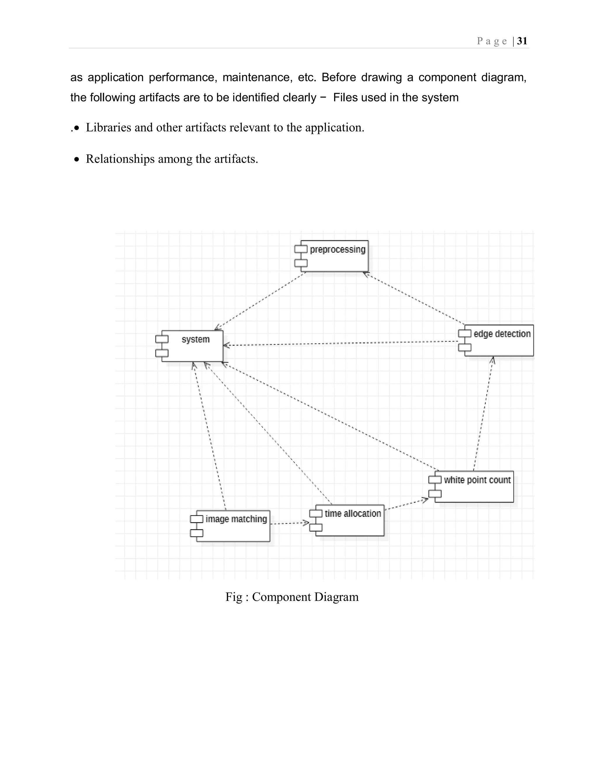
P a g e | 30  Identify the events Fig : State chart Diagram 5.1.6 Component diagram : Component diagrams are used to describe the physical artifacts of a system. This artifact includes files, executables, libraries, etc The purpose of this diagram is different. Component diagrams are used during the implementation phase of an application. However, it is prepared well in advance to visualize the implementation details. This diagram is very important as without it the application cannot be implemented efficiently. A well-prepared component diagram is also important for other aspects such
P a g e | 31 as application performance, maintenance, etc. Before drawing a component diagram, the following artifacts are to be identified clearly − Files used in the system . Libraries and other artifacts relevant to the application.  Relationships among the artifacts. Fig : Component Diagram
P a g e | 32 5.1.7 Deployment Diagram : Deployment diagram represents the deployment view of a system. It is related to the component diagram because the components are deployed using the deployment diagrams. A deployment diagram consists of nodes. Nodes are nothing but physical hardware used to deploy the application. Deployment diagrams are useful for system engineers. An efficient deployment diagram is very important as it controls the following parameters −  Scalability  Maintainability  Portability Before drawing a deployment diagram, the following artifacts should be identified − Nodes ,Relationships among nodes. Fig : Deployment Diagram
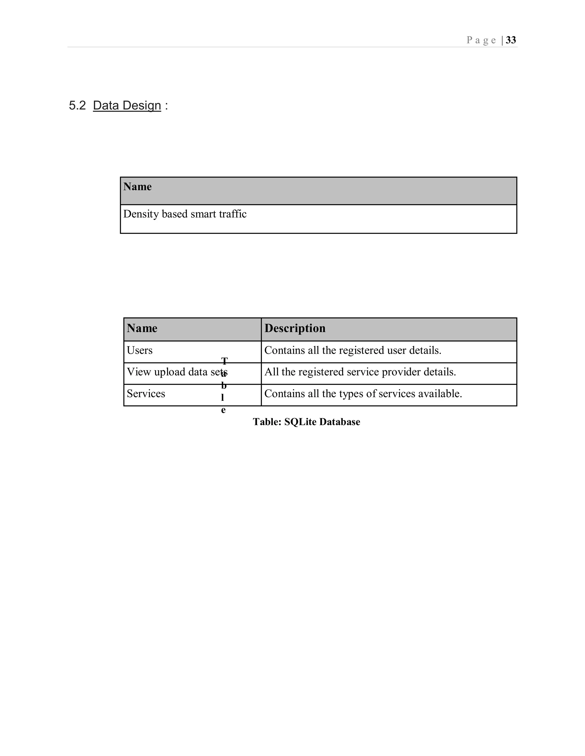
P a g e | 33 5.2 Data Design : T a b l e Table: SQLite Database Name Density based smart traffic Name Description Users Contains all the registered user details. View upload data sets All the registered service provider details. Services Contains all the types of services available.
P a g e | 34 6. Implementation  Introduction to MATLAB  Sample Code
P a g e | 35 6.Implementation : 6.1 INTRODUCTION TO MATLAB : The name MATLAB stands for MATrix LABoratory. MATLAB was written originally to provide easy access to matrix software developed by the LINPACK (linear system package) and EISPACK (Eigen system package) projects. MATLAB is a high- performance language for technical computing. It integrates computation, visualization, and programming environment. Furthermore, MATLAB is a modern programming language environment:These factors make MATLAB an excellent tool for teaching and research. MATLAB has many advantages compared to conventional computer languages (e.g., C, FORTRAN) for solving technical problems. Specific applications are collected in packages referred to as toolbox. There are toolboxes for signal processing, symbolic computation, control theory, simulation, optimization, and several other fields of applied science and engineering. 17 There are various tools in Matlab that can be utilized for image processing, such as Simulink, GUI etc. Simulink contains various toolboxes and image processing toolbox is one such example. Simulink is used for simulation of various projects. GUI is another important tool in Matlab.
P a g e | 36 6.2 SampleCode from tkinter import messagebox from tkinter import * from tkinter import simpledialog import tkinter from tkinter import filedialog import numpy as np from tkinter.filedialog import askopenfilename import numpy as np from CannyEdgeDetector import * import skimage import matplotlib.image as mpimg import os import scipy.misc as sm import cv2 import matplotlib.pyplot as plt main = tkinter.Tk() main.title("Density Based Smart Traffic Control System") main.geometry("1300x1200") def uploadTrafficImage(): global filename filename = filedialog.askopenfilename(initialdir="images") pathlabel.config(text=filename) def visualize(imgs, format=None, gray=False): j = 0 plt.figure(figsize=(20, 40)) for i, img in enumerate(imgs): if img.shape[0] == 3: img = img.transpose(1,2,0) plt_idx = i+1 plt.subplot(2, 2, plt_idx) if j == 0: plt.title('Sample Image') plt.imshow(img, format) j = j + 1 elif j > 0: plt.title('Reference Image') plt.imshow(img, format) plt.show() def applyCanny():
P a g e | 37 imgs = [] img = mpimg.imread(filename) img = rgb2gray(img) imgs.append(img) edge = CannyEdgeDetector(imgs, sigma=1.4, kernel_size=5, lowthreshold=0.09, highthreshold=0.20, weak_pixel=100) imgs = edge.detect() for i, img in enumerate(imgs): if img.shape[0] == 3: img = img.transpose(1,2,0) cv2.imwrite("gray/test.png",img) temp = [] img1 = mpimg.imread('gray/test.png') img2 = mpimg.imread('gray/refrence.png') temp.append(img1) temp.append(img2) visualize(temp) def pixelcount(): global refrence_pixels global sample_pixels img = cv2.imread('gray/test.png', cv2.IMREAD_GRAYSCALE) sample_pixels = np.sum(img == 255) img = cv2.imread('gray/refrence.png', cv2.IMREAD_GRAYSCALE) refrence_pixels = np.sum(img == 255) messagebox.showinfo("Pixel Counts", "Total Refrence White Pixels Count : "+str(sample_pixels)+"nTotal Sample White Pixels Count : "+str(refrence_pixels)) def timeAllocation(): avg = (sample_pixels/refrence_pixels) *100 if avg >= 90: messagebox.showinfo("Green Signal Allocation Time","Traffic is very high allocation green signal time : 60 secs") if avg > 85 and avg < 90: messagebox.showinfo("Green Signal Allocation Time","Traffic is high allocation green signal time : 50 secs") if avg > 75 and avg <= 85: messagebox.showinfo("Green Signal Allocation Time","Traffic is moderate green signal time : 40 secs") if avg > 50 and avg <= 75: messagebox.showinfo("Green Signal Allocation Time","Traffic is low allocation green signal time : 30 secs") if avg <= 50: messagebox.showinfo("Green Signal Allocation Time","Traffic is very low allocation green signal time : 20 secs")
P a g e | 38 def exit(): main.destroy()
P a g e | 39 7. System Testing  Unit Testing  Test Cases
P a g e | 40 7. TESTING : 7.1 SYSTEM TEST : The purpose of testing is to discover errors. Testing is the process of trying to discover every conceivable fault or weakness in a work product. It provides a way to check the functionality of components, sub assemblies, assemblies and/or a finished product It is the process of exercising software with the intent of ensuring that the Software system meets its requirements and user expectations and does not fail in an unacceptable manner. There are various types of test. Each test type addresses a specific testing requirement. TYPES OF TESTS : Unit testing Unit testing involves the design of test cases that validate that the internal program logic is functioning properly, and that program inputs produce valid outputs. All decision branches and internal code flow should be validated. It is the testing of individual software units of the application .it is done after the completion of an individual unit before integration. This is a structural testing, that relies on knowledge of its construction and is invasive. Unit tests perform basic tests at component level and test a specific business process, application, and/or system configuration. Unit tests ensure that each unique path of a business process performs accurately to the documented specifications and contains clearly defined inputs and expected results.
P a g e | 41 Integration testing : Integration tests are designed to test integrated software components to determine if they actually run as one program. Testing is event driven and is more concerned with the basic outcome of screens or fields. Integration tests demonstrate that although the components were individually satisfaction, as shown by successfully unit testing, the combination of components is correct and consistent. Integration testing is specifically aimed at exposing the problems that arise from the combination of components. Functional test : Functional tests provide systematic demonstrations that functions tested are available as specified by the business and technical requirements, system documentation, and user manuals. Functional testing is centered on the following items: Valid Input : identified classes of valid input must be accepted. Invalid Input : identified classes of invalid input must be rejected. Functions : identified functions must be exercised. Output : identified classes of application outputs must be excercised. Systems/Procedures : interfacing systems or procedures must be invoked. Organization and preparation of functional tests is focused on requirements, key functions, or special test cases. In addition, systematic coverage pertaining to identify Business process flows; data fields, predefined processes, and successive processes must be considered for testing. Before functional testing is complete, additional tests are
P a g e | 42 identified and the effective value of current tests is determined. System Test : System testing ensures that the entire integrated software system meets requirements. It tests a configuration to ensure known and predictable results. An example of system testing is the configuration oriented system integration test. System testing is based on process descriptions and flows, emphasizing pre-driven process links and integration points. 1.White Box Testing : White Box Testing is a testing in which in which the software tester has knowledge of the inner workings, structure and language of the software, or at least its purpose. It is purpose. It is used to test areas that cannot be reached from a black box level. 2.Black Box Testing : Black Box Testing is testing the software without any knowledge of the inner workings, structure or language of the module being tested. Black box tests, as most other kinds of tests, must be written from a definitive source document, such as specification or requirements document, such as specification or requirements document. It is a testing in which the software under test is treated, as a black box .you cannot “see” into it. The test provides inputs and responds to outputs without considering how the software works. 3.Unit Testing : Unit testing is usually conducted as part of a combined code and unit test phase of the software lifecycle, although it is not uncommon for coding and unit testing to be
P a g e | 43 conducted as two distinct phases. Test strategy and approach Field testing will be performed manually and functional tests will be written in detail. Test objectives  All field entries must work properly.  Pages must be activated from the identified link.  The entry screen, messages and responses must not be delayed. Features to be tested  Verify that the entries are of the correct format  No duplicate entries should be allowed  All links should take the user to the correct page. Integration Testing : Software integration testing is the incremental integration testing of two or more integrated software components on a single platform to produce failures caused by interface defects. The task of the integration test is to check that components or software applications, e.g. components in a software system or – one step up – software applications at the company level – interact without error. Test Results: All the test cases mentioned above passed successfully. No defects encountered. Acceptance Testing : User Acceptance Testing is a critical phase of any project and requires significant participation by the end user. It also ensures that the system meets the functional requirements.
P a g e | 44 Test Results:All the test cases mentioned above passed successfully. No defects encountered. 7.3 Test Cases : Test Case 1 Test Case Name Empty login fields testing Description In the login screen if the username and password fields are empty Output Login fails showing an alert box asking to enter username and password. Table: Test Case for Empty Login Fields Table: Test Case for Wrong Login Fields Table: Test Case for Signup fail Test Case 2 Test Case Name Wrong login fields testing Description A unique username and password are set by administrator. On entering wrong username or password gives. Output Login fails showing an alert box username or password incorrect. Test Case 3 Test Case Name User Signup Fails. Description User signup need to provide all data. Output Signup Fails and an alert message appears asking to enter valid email and name.
P a g e | 45 8.Output Screens
P a g e | 46 8.Output Screens : 8.1 Screen Captures : 8.1.1 User Login Screen: To implement this project we are using 4 input images given in paper and on reference image. Below are the images screen shots saved inside images folder. We can upload above 4 images to application to calculate traffic signal time. Screen shots
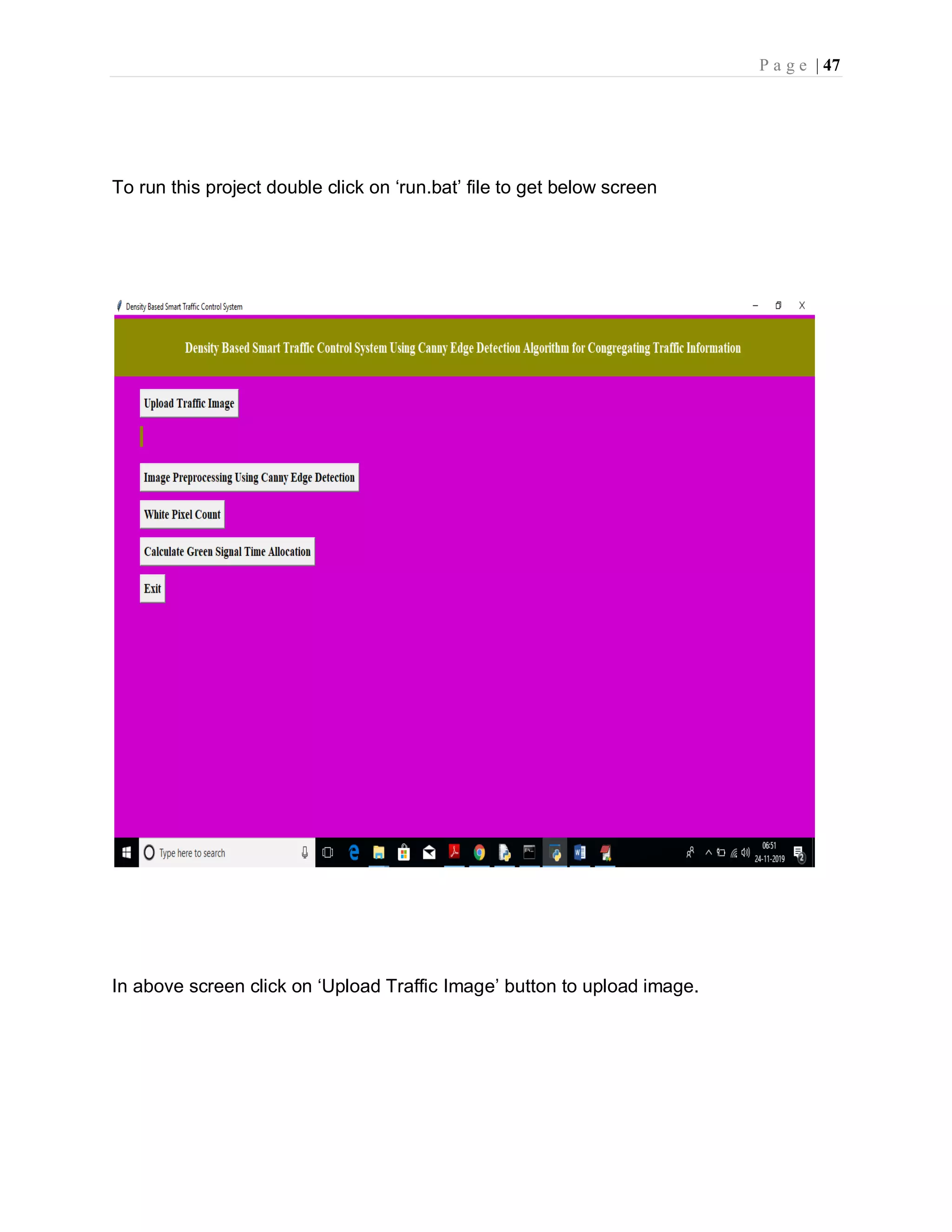
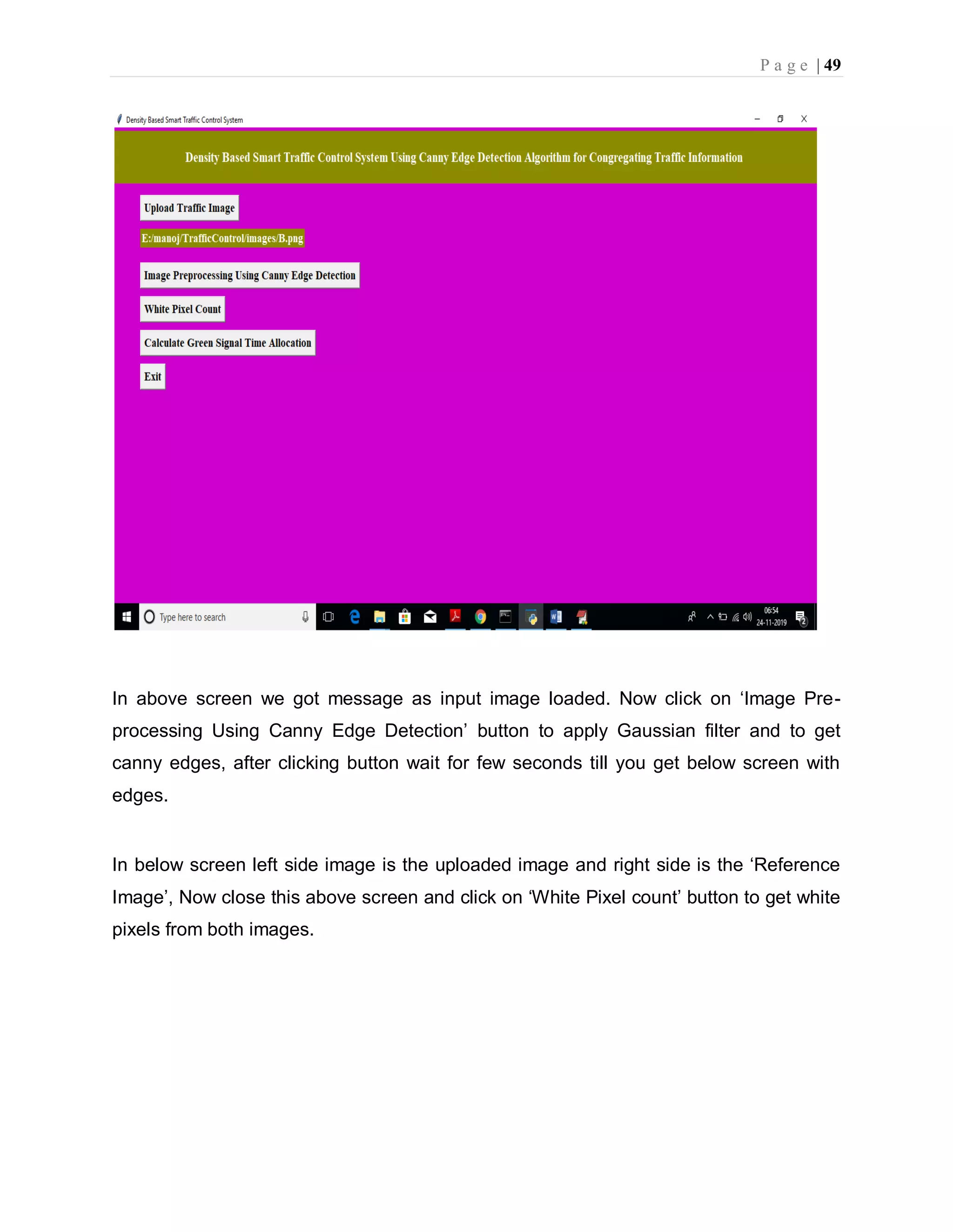
P a g e | 47 To run this project double click on ‘run.bat’ file to get below screen In above screen click on ‘Upload Traffic Image’ button to upload image.
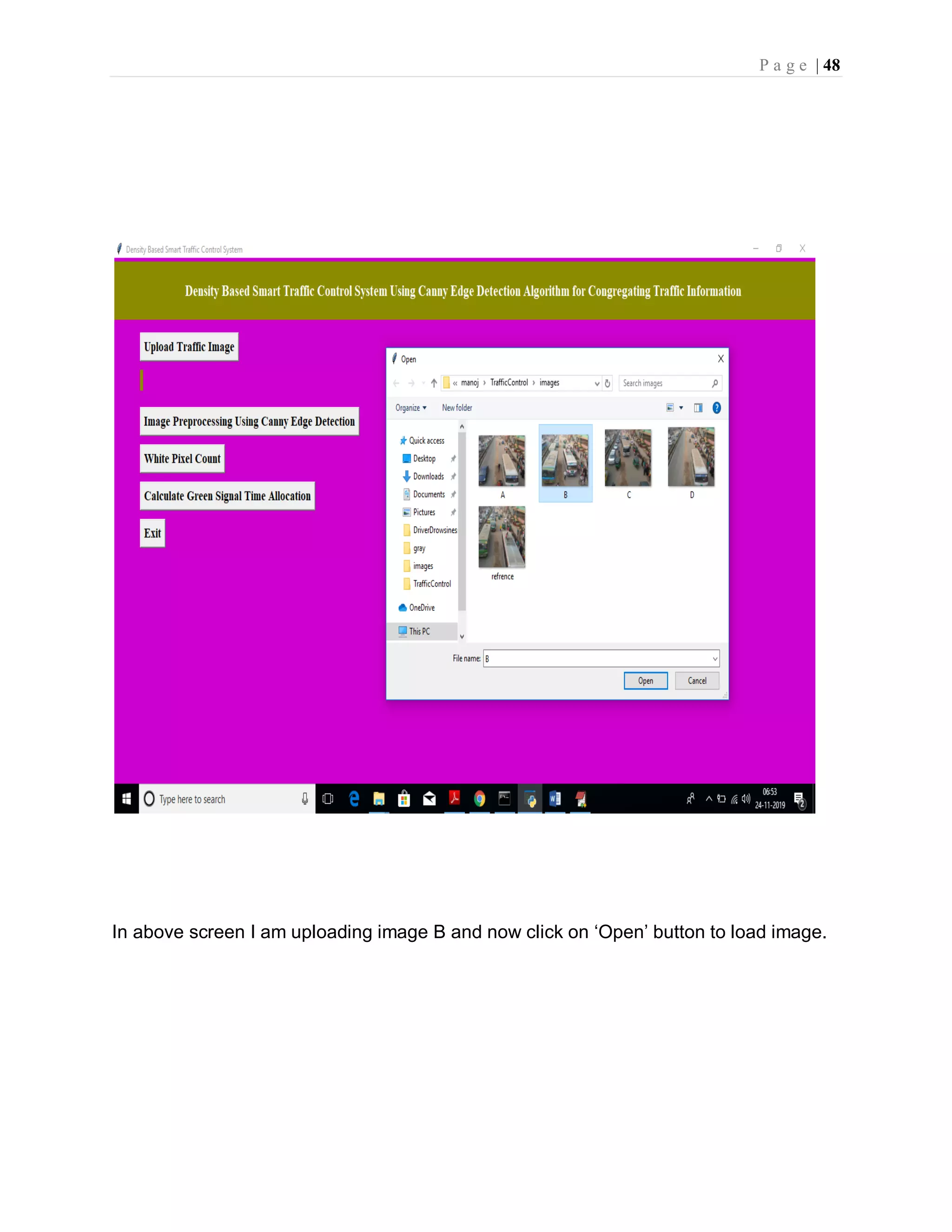
P a g e | 48 In above screen I am uploading image B and now click on ‘Open’ button to load image.
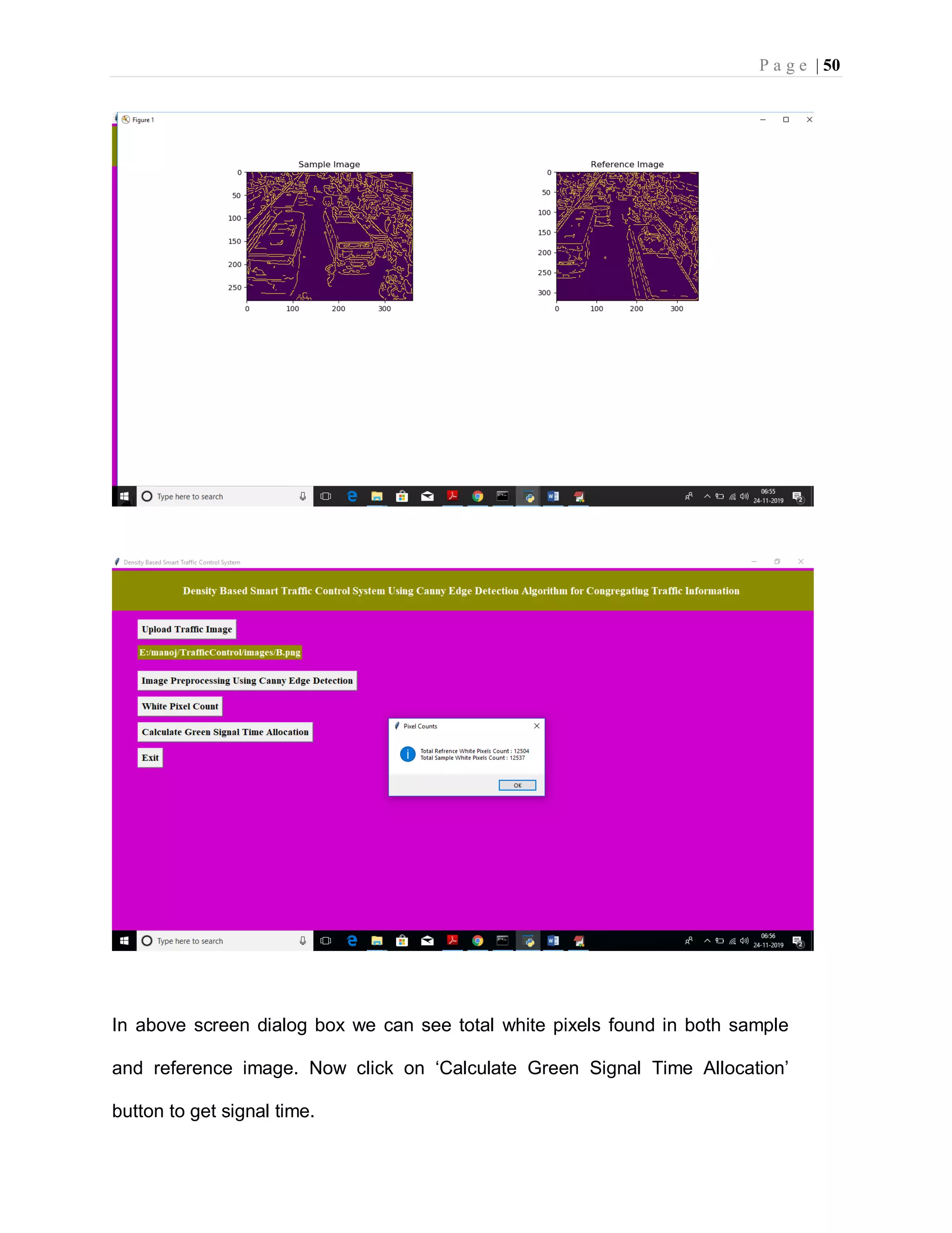
P a g e | 49 In above screen we got message as input image loaded. Now click on ‘Image Pre- processing Using Canny Edge Detection’ button to apply Gaussian filter and to get canny edges, after clicking button wait for few seconds till you get below screen with edges. In below screen left side image is the uploaded image and right side is the ‘Reference Image’, Now close this above screen and click on ‘White Pixel count’ button to get white pixels from both images.
P a g e | 50 In above screen dialog box we can see total white pixels found in both sample and reference image. Now click on ‘Calculate Green Signal Time Allocation’ button to get signal time.
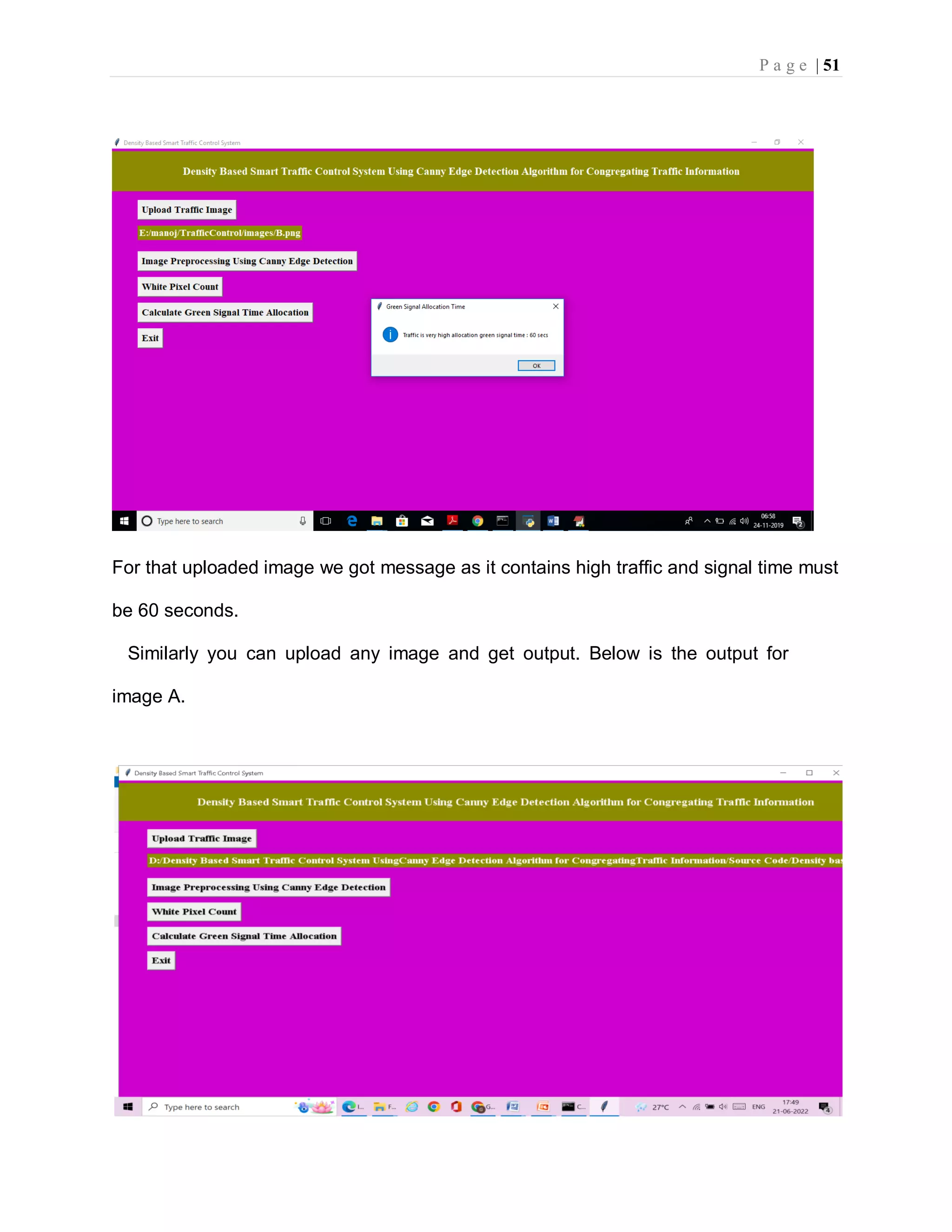
P a g e | 51 For that uploaded image we got message as it contains high traffic and signal time must be 60 seconds. Similarly you can upload any image and get output. Below is the output for image A.
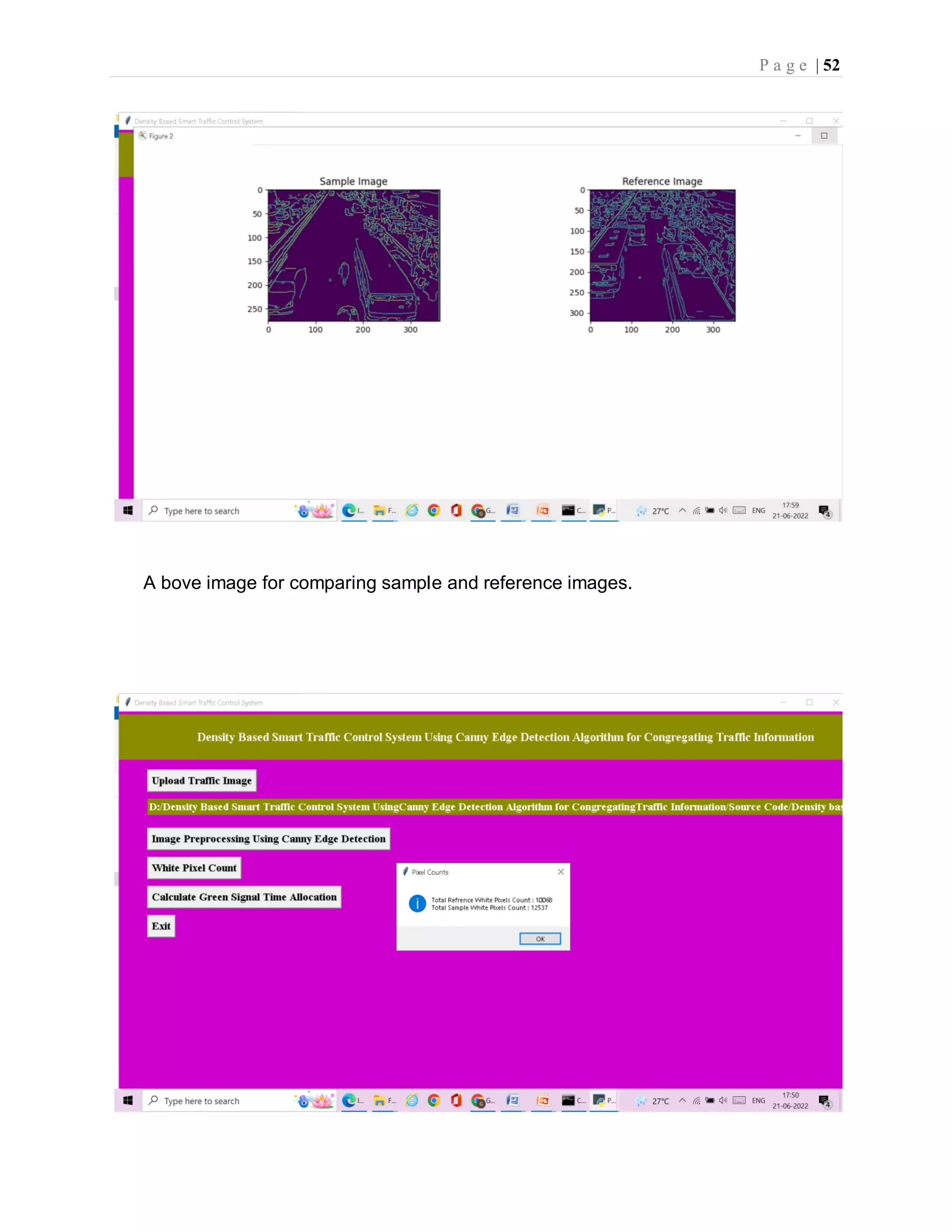
P a g e | 52 A bove image for comparing sample and reference images.
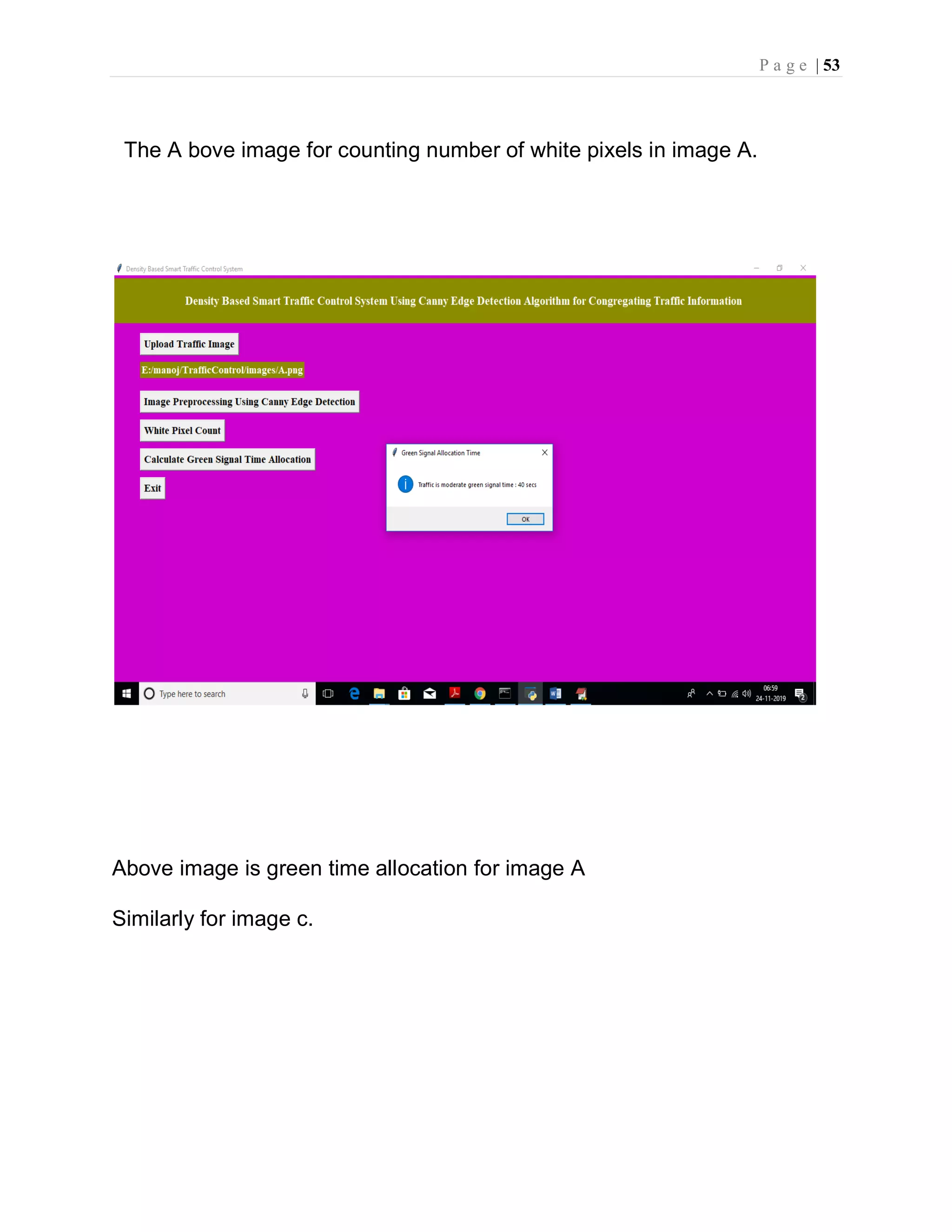
P a g e | 53 The A bove image for counting number of white pixels in image A. Above image is green time allocation for image A Similarly for image c.
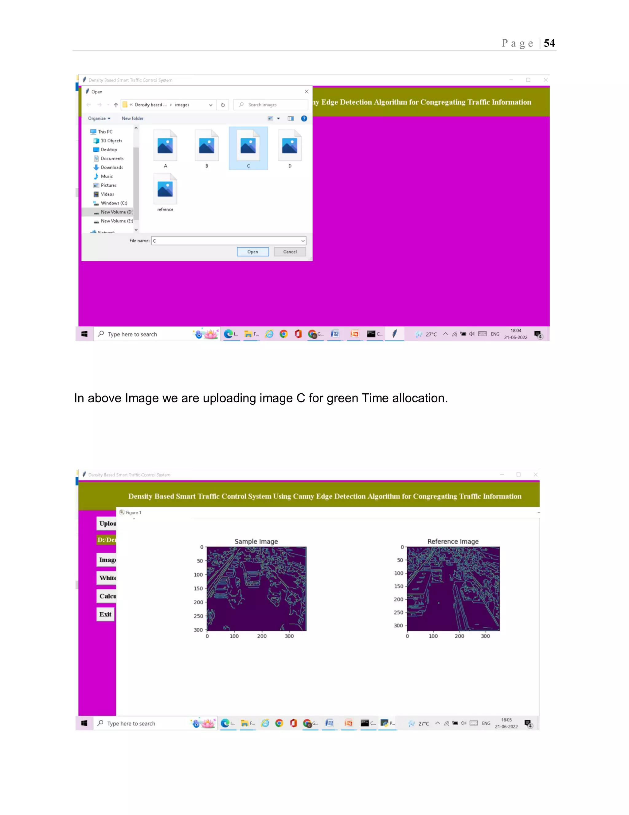
P a g e | 54 In above Image we are uploading image C for green Time allocation.
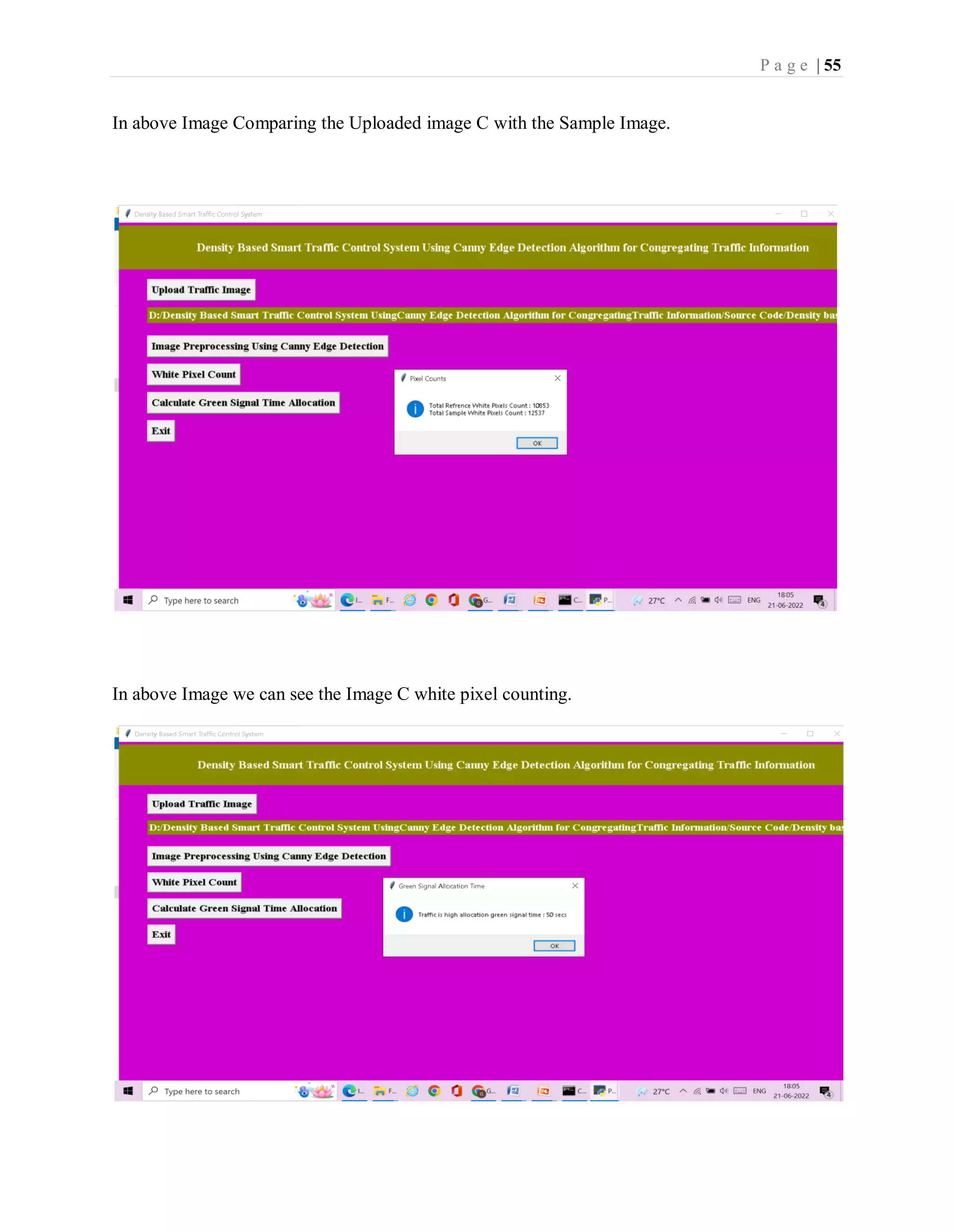
P a g e | 55 In above Image Comparing the Uploaded image C with the Sample Image. In above Image we can see the Image C white pixel counting.
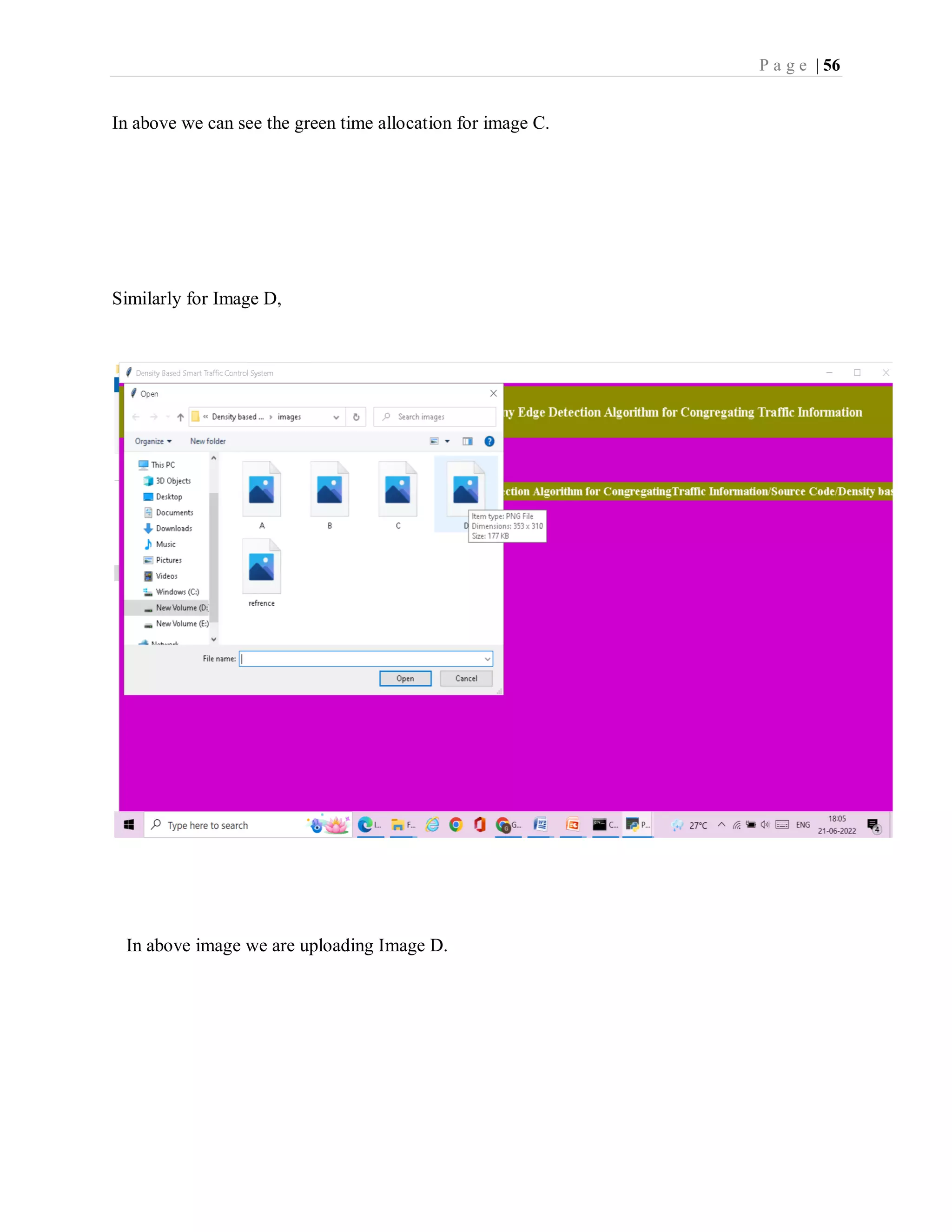
P a g e | 56 In above we can see the green time allocation for image C. Similarly for Image D, In above image we are uploading Image D.
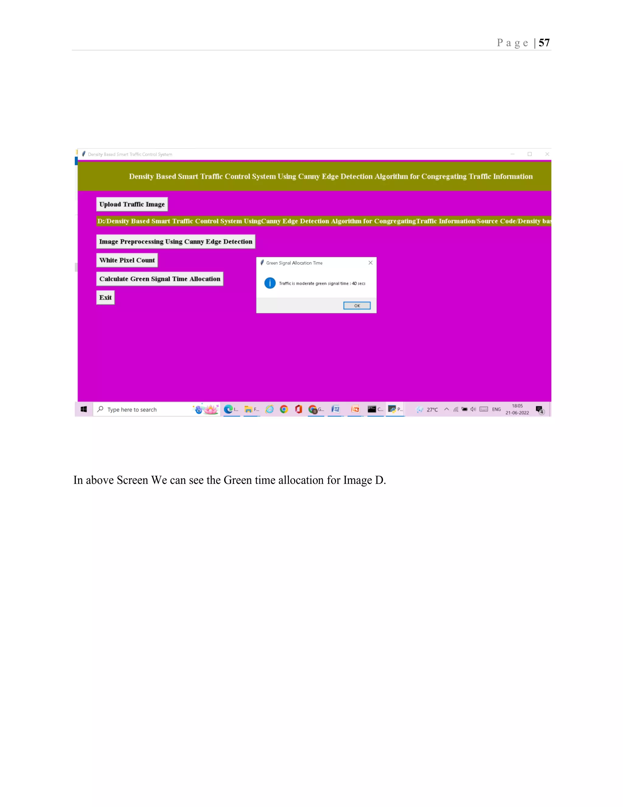
P a g e | 57 In above Screen We can see the Green time allocation for Image D.
P a g e | 58 9.Conclusion
P a g e | 59 9. CONCLUSION “Intelligent traffic control using image processing” technique that we propose overcomes all the limitations of the earlier (in use) techniques used for controlling the traffic. Earlier in automatic traffic control use of timer had a drawback that the time is being wasted by green light on the empty. This technique avoids this problem. Upon comparison of various edge detection algorithms, it was inferred that Canny Edge Detector technique is the most efficient one. The project demonstrates that image processing is a far more efficient method of traffic control as compared to traditional techniques. The use of our technique removes the need for extra hardware such as sound sensors. The increased response time for these vehicles is crucial for the prevention of loss of life. Major advantage is the variation in signal time which control appropriate traffic density using Image matching. The accuracy in calculation of time due to single moving camera depends on the registration position while facing road every time. Output of our code clearly indicated some expected results. It showed matching in almost every interval that were decided as boundaries like lots of traffic, more traffic and less traffic.
P a g e | 60 10. BIBLIOGRAPHY Code snippets for any errors http://stackoverflow.com/ Android Development Guide https://www.udemy.com/android Xml and Layout Guide https://www.androidhive.com/ Connecting to Firebase Docs https://firebase.google.com Software Testing http://en.wikipedia.org/wiki/Software_testing Manual Testing http://en.wikipedia.org/wiki/Manual_testing Performance Testing http://en.wikipedia.org/wiki/Software_performance_testing

smart traffic control system using canny edge detection algorithm (4).pdf

  • 1.
    DECLARATION Ms. G.Yamini bearingHT NO. 101319862022,here by declare that this project entitled “SMART TRAFFIC CONTROL SYSTEM USING CANNY EDGE DETECTION ALGORITHM”submitted to the Department of Computer Science,University Of College For Women, Koti, Hyderabad, in partial fulfillment for the award of Degree of MCA is entirely original and has not been submitted earlier by anyone for degree or diploma. No part of the project work is copied from books/journal/internet and whenever referred the same has been duly acknowledge in the text. The reported data are based on the project work done entirely by me and not copied from any other source. G.Yamini Signature of the Student Date
  • 2.
    UNIVERSITY OF COLLEGEFOR WOMEN (Autonomous) Koti, Hyderabad, Telangana state- 500 095 (Constituent College of Osmania University) CPE status & NAAC Re- Accredited – ‘A’ grade /UCW/ /20 Date : CERTIFICATE This is to certify that the project work entitled “ SMART TRAFFIC CONTROL SYSTEM USING CANNY EDGE DETECTION ALGORITHM” submitted by G.YAMINI, (MCA) bearing H.NO : 101319862022 is a bonofide work carried out by her under the guidance of Mrs. SAVITHA REDDY, Assistant professor, Department of Computer Science, University College For Women(Autonomous), Koti, Hyderabad during the Academic year 2021-2022. INTERNAL GUIDE EXTERNAL EXAMINER HEAD OF THE DEPARTMENT PRINCIPAL
  • 3.
    A PROJECT REPORT ON SMARTTRAFFIC CONTROL SYSTEM USING CANNY EDGE DETECTION ALGORITHM SUBMITTED IN PARTIAL FULFILMENT OF THE REQUIREMENT For the Award of Degree of MASTER OF COMPUTER APPLICATION (MCA) BY GOUDICHARLA YAMINI (HT.NO:101319862022) Under the Esteemed Guidance of Mrs. SAVITHA REDDY Assistant Professor(C), Department of CS, UCW DEPARTMENT OF COMPUTER SCIENCE UNIVERSITY OF COLLEGE FOR WOMEN(A) Osmaniauniversity,Hyderabad-500 095 2022
  • 4.
    ACKNOWLEDGEMENT This report isthe embodiment of the efforts of several people to whom I would like to express my gratitude. I profoundly thank Prof. M.VIJJU LATHA, Principal, University College for Women, Koti, Hyderabad for her continuous support I profoundly thank Dr. B.SHAILAJA, Vice Principal UCW, for the support provided I sincerely thank our Head of the Department Prof. K.KRISHNA CHAITANYA for her support during the project I sincerely thank our internal guide Mrs. SAVITHA REDDY, Assistant Professor for her continuous guidance and support during the completion of my project I would like to thank the ALMIGHTY, who gave me enough strength and health to complete my project without any interruption Last but not least, I thank all my family members and friends who are my source of encouragement through which I was able to complete the project work effectively and efficiently G.YAMINI 101319862022
  • 5.
    ABSTRACT In this paperauthor is describing concept to control or automate green traffic signal allotment time based on congestion available at road side using Canny Edge Detection Algorithm. To implement this technique we are uploading current traffic image to the application and application will extract edges from images and if there is more traffic then there will be more number of edges with white colour and if uploaded image contains less traffic then it will have less number of white colour edges. Empty edges will have black colour with value 0. By counting number of non-zeroes white pixels we will have complete idea of available traffic and based on that we will allocate time to green signal. If less traffic is there then green signal time will be less otherwise green signal allocation time will be more.
  • 6.
    INDEX SNO CONTENT PAGENO 1. INTRODUCTION 1 2. LITERATURE SURVEY 4 3. SYSTEM ANALYSIS 8 4. SYSTEM REQUIREMENTS AND SPECIFICATIONS 21 5. SYSTEM DESIGN 24 6. IMPLEMENTATION 34 7. TESTING 39 8. OUTPUT SCREENS 45 9. CONCLUSION 58 10. BIBLIOGRAPHY 60
  • 7.
    LIST OF CONTENTS SNOCONTENTS Page no 1. INTRODUCTION 1-3 2. LITERATURE SURVEY 4-7 3. SYSTEM ANALYSIS  EXISTING SYSTEM  DRAWBACKS  PROPOSED SYSTEM  ADVANTAGES  MODULES DESCRIPTION  FEASIBILITY STUDY  ECONOMIC FEASIBILITY  OPERATIONAL FEASIBILIY  TECHNICAL FEASIBILITY 8-20 4. SYSTEM REQUIREMENTS AND SPECIFICATIONS  HARDWARE REQUIREMENTS  SOFTWARE REQUIREMENTS 21-23 5. SYSTEM DESIGN  INTRODUCTION  UML DIAGRAMS  DATA DESIGN 24-33 6. IMPLEMENTATION  CODING 34-38
  • 8.
    7. TESTING  UNIT TESTING TEST CASES 39-44 8. OUTPUT SCREENS 45-57 9. CONCLUSION 58-59 10. BIBLIOGRAPHY 60
  • 9.
    1. INTRODUCTION  Purpose Scope of the Project  Objectives of the Project
  • 10.
    P a ge | 1 1.INTRODUCTION : • Traffic congestion is one of the major modern-day crisis in every big city in the world. Recent study of World Bank has shown that average vehicle speed has been reduced from 21 km to 7 km per hour in the last 10 years in Dhaka. • Inter metropolitan area studies suggest that traffic congestion reduces regional competitiveness and redistributes economic activity by slowing growth in county gross output or slowing metropolitan area employment growth. • As more and more vehicles are commissioning in an already congested traffic system, there is an urgent need for a whole new traffic control system using advanced technologies to utilize the already existent infrastructures to its full extent. • Since building new roads, flyovers, elevated expressway etc. needs extensive planning, huge capital and lots of time; focus should be directed upon availing existing infrastructures more efficiently and diligently. • Some of them count total number of pixels , some of the work calculate number of vehicles. These methods have shown promising results in collecting traffic data. • However, calculating the number of vehicles may give false results if the intra vehicular spacing is very small (two vehicles close to each other may be counted as one) and it may not count rickshaw or auto-rickshaw as vehicles which are the quotidian means of traffic especially in South-Asian countries. • And counting number of pixels has disadvantage of counting insubstantial materials as vehicles such as footpath or pedestrians. Some of the work have proposed to allocate time based solely on the density of traffic. But this may be disadvantageous for those who are in lanes that have less frequency of traffic.
  • 11.
    P a ge | 2 1.1 Scope for future work : The focus shall be to implement the controller using DSP as it can avoid heavy investment in industrial control computer while obtaining improved computational power and optimized system structure. The hardware implementation would enable the project to be used in real-time practical conditions. In addition, we propose a system to identify the vehicles as they pass by, giving preference to emergency vehicles and assisting in surveillance on a large scale.
  • 12.
    P a ge | 3 1.2 Objectives of the project :  The project processed a system for controlling the traffic light by image processing.  In this system the vehicles are not being detected by sensors, rather it is detected by images.  In this process initially the system will have picture of the traffic road. And the system will continuously taking pictures of the road and will compare those with traffic ones which will gives signal of the density of vehicles present on the road.  By detecting the density of vehicles ,light will glow, controlling the traffic. Since it will take the actual picture of the road, there will be very light chances of glowing the green signal when road is empty.
  • 13.
    P a ge | 4 2. Literature Survey
  • 14.
    P a ge | 5 Literature Survey : M. Sweet, “Traffic Congestion’s Economic Impacts: Evidence from US Metropolitan Regions,” Urban Studies, vol. 51, no. 10, pp. 2088–2110, Oct. 2013 Traffic congestion alleviation has long been a common core transport policy objective, but it remains unclear under which conditions this universal byproduct of urban life also impedes the economy. Using panel data for 88 US metropolitan statistical areas, this study estimates congestion’s drag on employment growth (1993 to 2008) and productivity growth per worker (2001 to 2007). Using instrumental variables, results suggest that congestion slows job growth above thresholds of approximately 4.5 minutes of delay per one-way auto commute and 11,000 average daily traffic (ADT) per lane on average across the regional freeway network. While higher ADT per freeway lane appears to slow productivity growth, there is no evidence of congestion-induced travel delay impeding productivity growth. Results suggest that the strict policy focus on travel time savings may be misplaced and, instead, better outlooks for managing congestion’s economic drag lie in prioritising the economically most important trips (perhaps through road pricing) or in providing alternative travel capacity to enable access despite congestion. Md. Munir Hasan, Gobinda Saha, Aminul Hoque and Md. Badruddoja Majumder, “Smart Traffic Control System with Application of Image Processing Techniques,”in 3rd International Conference on Informatic Electronics & Vision, Dhaka, May 2014. In this paper we propose a method for determining traffic congestion on roads using
  • 15.
    P a ge | 6 image processing techniques and a model for controlling traffic signals based on information received from images of roads taken by video camera. We extract traffic density which corresponds to total area occupied by vehicles on the road in terms of total amount of pixels in a video frame instead of calculating number of vehicles. We set two parameters as output, variable traffic cycle and weighted time for each road based on traffic density and control traffic lights in a sequential manner. Vismay Pandit, Jinesh Doshi, Dhruv Mehta, Ashay Mhatre and Abhilash Janardhan, “Smart Traffic Control System Using Image Processing,”International Journal of Emerging Trends & Technology in Computer Science (IJETTCS), Vol. 3, Issue 1, January – February 2014 In this paper we propose a method for determining traffic congestion on roads using image processing techniques and a model for controlling traffic signals based on information received from images of roads taken by video camera. We extract traffic density which corresponds to total area occupied by vehicles on the road in terms of total amount of pixels in a video frame instead of calculating number of vehicles. We set two parameters as output, variable traffic cycle and weighted time for each road based on traffic density and control traffic lights in a sequential manner. Pallavi Choudekar, Sayanti Banerjee and M. K. Muju, “Implementation of image processing in real time traffic light control,” in3rd International Conference on Electronics Computer Technology, April, 2011. In this paper we propose a method for determining traffic congestion on roads using image processing techniques and a model for controlling traffic signals based on
  • 16.
    P a ge | 7 information received from images of roads taken by video camera. We extract traffic density which corresponds to total area occupied by vehicles on the road in terms of total amount of pixels in a video frame instead of calculating number of vehicles. We set two parameters as output, variable traffic cycle and weighted time for each road based on traffic density and control traffic lights in a sequential manner.
  • 17.
    P a ge | 8 3. System analysis  Existing System  Proposed System  Block Diagram  Modules of the Application  System study
  • 18.
    P a ge | 9 3. SYSTEM ANALYSIS This chapter provides the details of the existing system and proposed system. 3.1 Existing System :- In present traffic control system it require man power to control the traffic. Depending on the countries and states the traffic polices are allotted for a required area or city to control traffic. The traffic polices will carry sign board, sign light and whistle to control the traffic. They will be instructed to wear specific uniforms in order to control the traffic. Previously different techniques had been proposed, such as infra-red light sensor, induction loop etc. to acquire traffic date which had their fair share of demerits. In recent years, image processing has shown promising outcomes in acquiring real time traffic information using CCTV footage installed along the traffic light. Drawbacks:- In the manual controlling system we need more man power. As we have poor strength of traffic police we cannot control traffic manually in all area of a city or town. So we need a better solution to control the traffic. On the other side, automatic traffic controlling a traffic light uses timer for every phase. Using electronic sensors is another way in order to detect vehicles, and produce signal that to this method the time is being wasted by a green light on an empty road. Traffic congestion also occurred while using the electronic sensors for controlling the traffic. All these drawbacks are supposed to be eliminated by using image processing.
  • 19.
    P a ge | 10 3.2 Proposed System :-  To implement this technique we are uploading current traffic image to the application and application will extract edges from images and if there is more traffic then there will be more number of edges with white colour and if uploaded image contains less traffic then it will have less number of white colour edges.  In this paper, a system in which density of traffic is measured by comparing captured image with real time traffic information against the image of the empty road as reference image is proposed. Here, in figure 1, the block diagram for proposed traffic control technique is illustrated.  Each lane will have a minimum amount of green signal duration allocated. According to the percentage of matching allocated traffic light duration can be controlled. The matching is achieved by comparing the number of white points between two images.  The entire image processing before edge detection i.e. image acquisition, image resizing, RGB to gray conversion and noise reduction. After that, canny edge detection operation and white point count are depicted. Canny edge detector operator is selected because of its greater overall performance.
  • 20.
    P a ge | 11 Advantages :- • It is advantageous to convert RGB images into grayscale for further processing. When converting an RGB image to grayscale, it is pertinent to consider the RGB values for each pixel and make as output a single value reflecting the brightness of that pixel. One of the approaches is to take the average of the contribution from each channel:(R+B+C)/3. Block Diagram of traffic control system :
  • 21.
    P a ge | 12 1.Image processing : Image processing involves issues related to image representation, compression techniques and various complex operations, which can be carried out on the image data. The operations that come under image processing are image enhancement operations such as sharpening, blurring, brightening, edge enhancement .Traffic density of lanes is calculated using image processing which is done of images of lanes that are captured using digital camera. We have chosen image processing for calculation of traffic density as cameras are very much cheaper than other devices. 2. Image Acquisition : Generally an image is a two-dimensional function f(x,y)(here x and y are plane coordinates).The amplitude of image at any point say f is called intensity of the image. It is also called the gray level of image at that point. We need to convert these x and y values to finite discrete values to form a digital image. The input image is a fundus taken from stare data base and drive data base. The image of the retina is taken for processing and to check the condition of the person. We need to convert the analog image to digital image to process it through digital computer. Each digital image composed of a finite elements and each finite element is called a pixel. 3. Image processing : i. Image Resizing/Scaling : Image scaling occurs in all digital photos at some stage whether this be in Bayer demosaicing or in photo enlargement. It happens anytime you resize your image from one pixel grid to another. Image resizing is necessary when you need to increase or decrease the total number of pixels. Even if the same image resize is performed, the result can vary significantly depending on the algorithm. Images are resized because of number of reasons but one of them is very important in our project. Every camera has
  • 22.
    P a ge | 13 its resolution, so when a system is designed for some camera specifications it will not run correctly for any other camera depending on specification similarities. so it is necessary to make the resolution constant for the application. ii. RGB to Gray Conversion : Humans perceive color through wavelength-sensitive sensory cells called cones. There are three different varieties of cones, each has a different sensitivity to electromagnetic radiation (light) of different wavelength. One cone is mainly sensitive to green light, one to red light, and one to blue light. By emitting a restricted combination of these three colors (red, green and blue), and hence stimulate the three types of cones at will, we are able to generate almost any detectable colour. iii. Image Enhancement : Image enhancement is the process of adjusting digital images so that the results are more suitable for display or further analysis. For example, we can eliminate noise, which will make it more easier to identify the key characteristics. In poor contrast images, the adjacent characters merge during binarization. We have to reduce the spread of the characters before applying a threshold to the word image. Hence, we introduce “POWER- LAW TRANSFORMATION” which increases the contrast of the characters and helps in better segmentation. 4. Edge Detection : Edge detection is the name for a set of mathematical methods which aim at identifying points in a digital image at which the image brightness changes sharply or, more technically, has discontinuities or noise. The points at which image brightness alters sharply are typically organized into a set of curved line segments termed edges. The
  • 23.
    P a ge | 14 same problem of detecting discontinuities in 1D signal is known as step detection and the problem of finding signal discontinuities over time is known as change detection. Edge detection is a basic tool in image processing, machine vision and computer envisage, particularly in the areas of feature reveal and feature extraction. 4.1 Edge Detection Techniques : Different colours have different brightness values of particular colour. Green image has more bright than red and blue image or blue image is blurred image and red image is the high noise image. Following are list of various edge-detection methods:-  Sobel Edge Detection Technique  Perwitt Edge Detection  Roberts Edge Detection Technique  Zero cross Threshold Edge Detection Technique  Canny Edge Detection Technique In our project we use “CANNY EDGE DETECTION TECHNIQUE” because of its various advantages over other edge detection techniques. 5. Canny Edge Detection : The Canny Edge Detector is one of the most commonly used image processing tools detecting edges in a very robust manner. It is a multi-step process, which can be implemented on the GPU as a sequence of filters. Canny edge detection technique is based on three basic objectives.
  • 24.
    P a ge | 15 5.1 Low error rate:- All edges should be found, and there should be no spurious responses. That is, the edges must be as close as possible to the true edges. 5.2 Edge point should be well localized:- The edges located must be as close as possible to the true edges. That is , the distance between a point marked as an edge by the detector and the centre of the true edge should be minimum.
  • 25.
    P a ge | 16 5.3 Single edge point response:- The detector should return only one point for each true edge point. That is, the number of local maxima around the true edge should be minimum. This means that the detector should not identify multiple edge pixels where only a single edge point exists. Canny edge detection algorithm consist of the following basic steps: i. Smooth the input image with Gaussian filter. ii. Compute the gradient magnitude and angle images. iii. Apply non-maxima suppression to the gradient magnitude image. iv. Use double thresh holding and connectivity analysis to detect and link edges. 6. Image Matching : Comparing a reference image with the real time image pixel by pixel. Though there are so many disadvantages related to pixel based matching but it is one of the best techniques for the algorithm which is used in the project for decision making. Real image is stored in matric in memory and the real time image is also converted in the desired matric. For images to be same their pixel values in matrix must be same. This is the simplest fact used in pixel matching. If there is any mismatch in pixel value it adds on to the counter used to calculate number of pixel mismatches. Finally percentage of matching is expressed as The block diagram of the proposed algorithm discussed above is implemented in MATLAB R2013a. So it is necessary to gain an insight of MATLAB.
  • 26.
    P a ge | 17 Fig : Image Processing
  • 27.
    P a ge | 18 3.3 Modules of the Application:  Upload Image Module  Pre Process Module  White pixel count Module Upload Image Module: In this module current traffic image will be uploaded to application and then convert colour image into Gray Scale image format to have pixels values as black and white colour. Pre-process module: In this module Gaussian Filter will be applied on uploaded image to convert image into smooth format. After applying filter Canny Edge Detection will be applied on image to get edges from the image. Each vehicle will have white colour pixels and non-vehicle will have black colour pixels. White Pixel Count Module: Using this module we will count white pixels from canny image to get complete traffic count. Calculate Green Signal Time Allocation Module: Based on white pixel count traffic signal time will be calculated. How this time will be calculated is already explain in previous page.
  • 28.
    P a ge | 19 3.4 System Study : Feasibility Study : The feasibility of the project is analyzed in this phase and business proposal is put forth with a very general plan for the project and some cost estimates. During system analysis the feasibility study of the proposed system is to be carried out. This is to ensure that the proposed system is not a burden to the company. For feasibility analysis, some understanding of the major requirements for the system is essential. Three key considerations involved in the feasibility analysis are :  ECONOMICAL FEASIBILITY  TECHNICAL FEASIBILITY  SOCIAL FEASIBILITY 3.4.1 ECONOMICAL FEASIBILITY : This study is carried out to check the economic impact that the system will have on the organization. The amount of fund that the company can pour into the research and development of the system is limited. The expenditures must be justified. Thus the developed system as well within the budget and this was achieved because most of the technologies used are freely available. Only the customized products had to be purchased.
  • 29.
    P a ge | 20 3.4.2 TECHNICAL FEASIBILITY : This study is carried out to check the technical feasibility, that is, the technical requirements of the system. Any system developed must not have a high demand on the available technical resources. This will lead to high demands on the available technical resources. This will lead to high demands being placed on the client. The developed system must have a modest requirement, as only minimal or null changes are required for implementing this system. 3.4.3 SOCIAL FEASIBILITY : The aspect of study is to check the level of acceptance of the system by the user. This includes the process of training the user to use the system efficiently. The user must not feel threatened by the system, instead must accept it as a necessity. The level of acceptance by the users solely depends on the methods that are employed to educate the user about the system and to make him familiar with it. His level of confidence must be raised so that he is also able to make some constructive criticism, which is welcomed, as he is the final user of the system.
  • 30.
    P a ge | 21 4. System Requirements and Specifications  Hardware Requirements  Software Requirements
  • 31.
    P a ge | 22 4. REQUIREMENT ANALYSIS : The project involved analyzing the design of few applications so as to make the application more users friendly. To do so, it was really important to keep the navigations from one screen to the other well ordered and at the same time reducing the amount of typing the user needs to do. In order to make the application more accessible, the browser version had to be chosen so that it is compatible with most of the Browsers. REQUIREMENT SPECIFICATION : Functional Requirements  Graphical User interface with the User. 4.1 Software Requirements For developing the application the following are the Software Requirements: 1. Python 2. Django Operating Systems supported 1. Windows 7 2. Windows XP 3. Windows 8 Technologies and Languages used to Develop
  • 32.
    P a ge | 23 1. Python Debugger and Emulator  Any Browser (Particularly Chrome) 4.2 Hardware Requirements For developing the application the following are the Hardware Requirements:  Processor : Pentium IV or higher  RAM : 256 MB  Space on Hard Disk : minimum 512MB
  • 33.
    P a ge | 24 5. System Design  UML Diagrams
  • 34.
    P a ge | 25 5.DESIGN PHASE INTRODUCTION : This chapter provides the design phase of the Application. To design the project, we use the UML diagrams. The Unified Modelling Language (UML) is a general- purpose, developmental, modelling language in the field of software engineering that is intended to provide a standard way to visualize the design of a system. 5.1Uml diagrams : UML stands for Unified Modeling Language. UML is a standardized generalpurpose modeling language in the field of object-oriented software engineering. The standard is managed, and was created by, the Object Management Group. The Unified Modeling Language is a standard language for specifying, Visualization, Constructing and documenting the artifacts of software system, as well as for business modeling and other non-software systems. The UML is a very important part of developing objects oriented software and the software development process. The UML uses mostly graphical notations to express the design of software projects. GOALS: The Primary goals in the design of the UML are as follows: 1. Provide users a ready-to-use, expressive visual modeling Language so that they can develop and exchange meaningful models. 2. Provide extendibility and specialization mechanisms to extend the core concepts. 3. Be independent of particular programming languages and development process. 4. Provide a formal basis for understanding the modeling language.
  • 35.
    P a ge | 26 5. Encourage the growth of OO tools market. 6. Support higher level development concepts such as collaborations,frameworks, Patterns. 7. Integrate best practices. 5.1.1 USE CASE DIAGRAM: A use case diagram in the Unified Modeling Language (UML) is a type of behavioral diagram defined by and created from a Use-case analysis. Its purpose is to present a graphical overview of the functionality provided by a system in terms of actors, their goals (represented as use cases), and any dependencies between those use cases. The main purpose of a use case diagram is to show what system functions are performed for which actor. Roles of the actors in the system can be depicted.
  • 36.
    P a ge | 27 Fig :Use case Diagram 5.1.2 CLASS DIAGRAM : In software engineering, a class diagram in the Unified Modeling Language (UML) is a type of static structure diagram that describes the structure of a system by showing the system's classes, their attributes, operations (or methods), and the relationships among the classes. It explains which class contains information. Fig : Class Diagram 5.1.3 SEQUENCE DIAGRAM : A sequence diagram in Unified Modeling Language (UML) is a kind of interaction diagram that shows how processes operate with one another and in what order. It is a construct of a Message Sequence Chart. Sequence
  • 37.
    P a ge | 28 diagrams are sometimes called event diagrams, event scenarios, and timing diagrams. Fig : Sequence Diagram 5.1.4 ACTIVITY DIAGRAM : Activity diagrams are graphical representations of workflows of stepwise activities and actions with support for choice, iteration and concurrency. In the Unified Modeling Language, activity diagrams can be used to describe the business and operational step- by-step workflows of components in a system.
  • 38.
    P a ge | 29 Fig : Activity Diagram 5.1.5 State chart diagram : State chart diagram is used to describe the states of different objects in its life cycle. Emphasis is placed on the state changes upon some internal or external events. These states of objects are important to analyze and implement them accurately. Statechart diagrams are very important for describing the states. States can be identified as the condition of objects when a particular event occurs. Before drawing a Statechart diagram we should clarify the following points − Identify the important objects to be analyzed.  Identify the states.
  • 39.
    P a ge | 30  Identify the events Fig : State chart Diagram 5.1.6 Component diagram : Component diagrams are used to describe the physical artifacts of a system. This artifact includes files, executables, libraries, etc The purpose of this diagram is different. Component diagrams are used during the implementation phase of an application. However, it is prepared well in advance to visualize the implementation details. This diagram is very important as without it the application cannot be implemented efficiently. A well-prepared component diagram is also important for other aspects such
  • 40.
    P a ge | 31 as application performance, maintenance, etc. Before drawing a component diagram, the following artifacts are to be identified clearly − Files used in the system . Libraries and other artifacts relevant to the application.  Relationships among the artifacts. Fig : Component Diagram
  • 41.
    P a ge | 32 5.1.7 Deployment Diagram : Deployment diagram represents the deployment view of a system. It is related to the component diagram because the components are deployed using the deployment diagrams. A deployment diagram consists of nodes. Nodes are nothing but physical hardware used to deploy the application. Deployment diagrams are useful for system engineers. An efficient deployment diagram is very important as it controls the following parameters −  Scalability  Maintainability  Portability Before drawing a deployment diagram, the following artifacts should be identified − Nodes ,Relationships among nodes. Fig : Deployment Diagram
  • 42.
    P a ge | 33 5.2 Data Design : T a b l e Table: SQLite Database Name Density based smart traffic Name Description Users Contains all the registered user details. View upload data sets All the registered service provider details. Services Contains all the types of services available.
  • 43.
    P a ge | 34 6. Implementation  Introduction to MATLAB  Sample Code
  • 44.
    P a ge | 35 6.Implementation : 6.1 INTRODUCTION TO MATLAB : The name MATLAB stands for MATrix LABoratory. MATLAB was written originally to provide easy access to matrix software developed by the LINPACK (linear system package) and EISPACK (Eigen system package) projects. MATLAB is a high- performance language for technical computing. It integrates computation, visualization, and programming environment. Furthermore, MATLAB is a modern programming language environment:These factors make MATLAB an excellent tool for teaching and research. MATLAB has many advantages compared to conventional computer languages (e.g., C, FORTRAN) for solving technical problems. Specific applications are collected in packages referred to as toolbox. There are toolboxes for signal processing, symbolic computation, control theory, simulation, optimization, and several other fields of applied science and engineering. 17 There are various tools in Matlab that can be utilized for image processing, such as Simulink, GUI etc. Simulink contains various toolboxes and image processing toolbox is one such example. Simulink is used for simulation of various projects. GUI is another important tool in Matlab.
  • 45.
    P a ge | 36 6.2 SampleCode from tkinter import messagebox from tkinter import * from tkinter import simpledialog import tkinter from tkinter import filedialog import numpy as np from tkinter.filedialog import askopenfilename import numpy as np from CannyEdgeDetector import * import skimage import matplotlib.image as mpimg import os import scipy.misc as sm import cv2 import matplotlib.pyplot as plt main = tkinter.Tk() main.title("Density Based Smart Traffic Control System") main.geometry("1300x1200") def uploadTrafficImage(): global filename filename = filedialog.askopenfilename(initialdir="images") pathlabel.config(text=filename) def visualize(imgs, format=None, gray=False): j = 0 plt.figure(figsize=(20, 40)) for i, img in enumerate(imgs): if img.shape[0] == 3: img = img.transpose(1,2,0) plt_idx = i+1 plt.subplot(2, 2, plt_idx) if j == 0: plt.title('Sample Image') plt.imshow(img, format) j = j + 1 elif j > 0: plt.title('Reference Image') plt.imshow(img, format) plt.show() def applyCanny():
  • 46.
    P a ge | 37 imgs = [] img = mpimg.imread(filename) img = rgb2gray(img) imgs.append(img) edge = CannyEdgeDetector(imgs, sigma=1.4, kernel_size=5, lowthreshold=0.09, highthreshold=0.20, weak_pixel=100) imgs = edge.detect() for i, img in enumerate(imgs): if img.shape[0] == 3: img = img.transpose(1,2,0) cv2.imwrite("gray/test.png",img) temp = [] img1 = mpimg.imread('gray/test.png') img2 = mpimg.imread('gray/refrence.png') temp.append(img1) temp.append(img2) visualize(temp) def pixelcount(): global refrence_pixels global sample_pixels img = cv2.imread('gray/test.png', cv2.IMREAD_GRAYSCALE) sample_pixels = np.sum(img == 255) img = cv2.imread('gray/refrence.png', cv2.IMREAD_GRAYSCALE) refrence_pixels = np.sum(img == 255) messagebox.showinfo("Pixel Counts", "Total Refrence White Pixels Count : "+str(sample_pixels)+"nTotal Sample White Pixels Count : "+str(refrence_pixels)) def timeAllocation(): avg = (sample_pixels/refrence_pixels) *100 if avg >= 90: messagebox.showinfo("Green Signal Allocation Time","Traffic is very high allocation green signal time : 60 secs") if avg > 85 and avg < 90: messagebox.showinfo("Green Signal Allocation Time","Traffic is high allocation green signal time : 50 secs") if avg > 75 and avg <= 85: messagebox.showinfo("Green Signal Allocation Time","Traffic is moderate green signal time : 40 secs") if avg > 50 and avg <= 75: messagebox.showinfo("Green Signal Allocation Time","Traffic is low allocation green signal time : 30 secs") if avg <= 50: messagebox.showinfo("Green Signal Allocation Time","Traffic is very low allocation green signal time : 20 secs")
  • 47.
    P a ge | 38 def exit(): main.destroy()
  • 48.
    P a ge | 39 7. System Testing  Unit Testing  Test Cases
  • 49.
    P a ge | 40 7. TESTING : 7.1 SYSTEM TEST : The purpose of testing is to discover errors. Testing is the process of trying to discover every conceivable fault or weakness in a work product. It provides a way to check the functionality of components, sub assemblies, assemblies and/or a finished product It is the process of exercising software with the intent of ensuring that the Software system meets its requirements and user expectations and does not fail in an unacceptable manner. There are various types of test. Each test type addresses a specific testing requirement. TYPES OF TESTS : Unit testing Unit testing involves the design of test cases that validate that the internal program logic is functioning properly, and that program inputs produce valid outputs. All decision branches and internal code flow should be validated. It is the testing of individual software units of the application .it is done after the completion of an individual unit before integration. This is a structural testing, that relies on knowledge of its construction and is invasive. Unit tests perform basic tests at component level and test a specific business process, application, and/or system configuration. Unit tests ensure that each unique path of a business process performs accurately to the documented specifications and contains clearly defined inputs and expected results.
  • 50.
    P a ge | 41 Integration testing : Integration tests are designed to test integrated software components to determine if they actually run as one program. Testing is event driven and is more concerned with the basic outcome of screens or fields. Integration tests demonstrate that although the components were individually satisfaction, as shown by successfully unit testing, the combination of components is correct and consistent. Integration testing is specifically aimed at exposing the problems that arise from the combination of components. Functional test : Functional tests provide systematic demonstrations that functions tested are available as specified by the business and technical requirements, system documentation, and user manuals. Functional testing is centered on the following items: Valid Input : identified classes of valid input must be accepted. Invalid Input : identified classes of invalid input must be rejected. Functions : identified functions must be exercised. Output : identified classes of application outputs must be excercised. Systems/Procedures : interfacing systems or procedures must be invoked. Organization and preparation of functional tests is focused on requirements, key functions, or special test cases. In addition, systematic coverage pertaining to identify Business process flows; data fields, predefined processes, and successive processes must be considered for testing. Before functional testing is complete, additional tests are
  • 51.
    P a ge | 42 identified and the effective value of current tests is determined. System Test : System testing ensures that the entire integrated software system meets requirements. It tests a configuration to ensure known and predictable results. An example of system testing is the configuration oriented system integration test. System testing is based on process descriptions and flows, emphasizing pre-driven process links and integration points. 1.White Box Testing : White Box Testing is a testing in which in which the software tester has knowledge of the inner workings, structure and language of the software, or at least its purpose. It is purpose. It is used to test areas that cannot be reached from a black box level. 2.Black Box Testing : Black Box Testing is testing the software without any knowledge of the inner workings, structure or language of the module being tested. Black box tests, as most other kinds of tests, must be written from a definitive source document, such as specification or requirements document, such as specification or requirements document. It is a testing in which the software under test is treated, as a black box .you cannot “see” into it. The test provides inputs and responds to outputs without considering how the software works. 3.Unit Testing : Unit testing is usually conducted as part of a combined code and unit test phase of the software lifecycle, although it is not uncommon for coding and unit testing to be
  • 52.
    P a ge | 43 conducted as two distinct phases. Test strategy and approach Field testing will be performed manually and functional tests will be written in detail. Test objectives  All field entries must work properly.  Pages must be activated from the identified link.  The entry screen, messages and responses must not be delayed. Features to be tested  Verify that the entries are of the correct format  No duplicate entries should be allowed  All links should take the user to the correct page. Integration Testing : Software integration testing is the incremental integration testing of two or more integrated software components on a single platform to produce failures caused by interface defects. The task of the integration test is to check that components or software applications, e.g. components in a software system or – one step up – software applications at the company level – interact without error. Test Results: All the test cases mentioned above passed successfully. No defects encountered. Acceptance Testing : User Acceptance Testing is a critical phase of any project and requires significant participation by the end user. It also ensures that the system meets the functional requirements.
  • 53.
    P a ge | 44 Test Results:All the test cases mentioned above passed successfully. No defects encountered. 7.3 Test Cases : Test Case 1 Test Case Name Empty login fields testing Description In the login screen if the username and password fields are empty Output Login fails showing an alert box asking to enter username and password. Table: Test Case for Empty Login Fields Table: Test Case for Wrong Login Fields Table: Test Case for Signup fail Test Case 2 Test Case Name Wrong login fields testing Description A unique username and password are set by administrator. On entering wrong username or password gives. Output Login fails showing an alert box username or password incorrect. Test Case 3 Test Case Name User Signup Fails. Description User signup need to provide all data. Output Signup Fails and an alert message appears asking to enter valid email and name.
  • 54.
    P a ge | 45 8.Output Screens
  • 55.
    P a ge | 46 8.Output Screens : 8.1 Screen Captures : 8.1.1 User Login Screen: To implement this project we are using 4 input images given in paper and on reference image. Below are the images screen shots saved inside images folder. We can upload above 4 images to application to calculate traffic signal time. Screen shots
  • 56.
    P a ge | 47 To run this project double click on ‘run.bat’ file to get below screen In above screen click on ‘Upload Traffic Image’ button to upload image.
  • 57.
    P a ge | 48 In above screen I am uploading image B and now click on ‘Open’ button to load image.
  • 58.
    P a ge | 49 In above screen we got message as input image loaded. Now click on ‘Image Pre- processing Using Canny Edge Detection’ button to apply Gaussian filter and to get canny edges, after clicking button wait for few seconds till you get below screen with edges. In below screen left side image is the uploaded image and right side is the ‘Reference Image’, Now close this above screen and click on ‘White Pixel count’ button to get white pixels from both images.
  • 59.
    P a ge | 50 In above screen dialog box we can see total white pixels found in both sample and reference image. Now click on ‘Calculate Green Signal Time Allocation’ button to get signal time.
  • 60.
    P a ge | 51 For that uploaded image we got message as it contains high traffic and signal time must be 60 seconds. Similarly you can upload any image and get output. Below is the output for image A.
  • 61.
    P a ge | 52 A bove image for comparing sample and reference images.
  • 62.
    P a ge | 53 The A bove image for counting number of white pixels in image A. Above image is green time allocation for image A Similarly for image c.
  • 63.
    P a ge | 54 In above Image we are uploading image C for green Time allocation.
  • 64.
    P a ge | 55 In above Image Comparing the Uploaded image C with the Sample Image. In above Image we can see the Image C white pixel counting.
  • 65.
    P a ge | 56 In above we can see the green time allocation for image C. Similarly for Image D, In above image we are uploading Image D.
  • 66.
    P a ge | 57 In above Screen We can see the Green time allocation for Image D.
  • 67.
    P a ge | 58 9.Conclusion
  • 68.
    P a ge | 59 9. CONCLUSION “Intelligent traffic control using image processing” technique that we propose overcomes all the limitations of the earlier (in use) techniques used for controlling the traffic. Earlier in automatic traffic control use of timer had a drawback that the time is being wasted by green light on the empty. This technique avoids this problem. Upon comparison of various edge detection algorithms, it was inferred that Canny Edge Detector technique is the most efficient one. The project demonstrates that image processing is a far more efficient method of traffic control as compared to traditional techniques. The use of our technique removes the need for extra hardware such as sound sensors. The increased response time for these vehicles is crucial for the prevention of loss of life. Major advantage is the variation in signal time which control appropriate traffic density using Image matching. The accuracy in calculation of time due to single moving camera depends on the registration position while facing road every time. Output of our code clearly indicated some expected results. It showed matching in almost every interval that were decided as boundaries like lots of traffic, more traffic and less traffic.
  • 69.
    P a ge | 60 10. BIBLIOGRAPHY Code snippets for any errors http://stackoverflow.com/ Android Development Guide https://www.udemy.com/android Xml and Layout Guide https://www.androidhive.com/ Connecting to Firebase Docs https://firebase.google.com Software Testing http://en.wikipedia.org/wiki/Software_testing Manual Testing http://en.wikipedia.org/wiki/Manual_testing Performance Testing http://en.wikipedia.org/wiki/Software_performance_testing