Download to read offline
![IJRET: International Journal of Research in Engineering and Technology ISSN: 2319-1163 __________________________________________________________________________________________ Volume: 02 Issue: 06 | Jun-2013, Available @ http://www.ijret.org 950 POWER QUALITY IMPROVEMENT OF GRID INTERCONNECTED DISTRIBUTION SYSTEM USING FSS-LMS ALGORITHM R.Dhinesh Kumar1 , V.Malathi2 1 PG student,2 Professor/HOD, Dept. ofElectrical and Electronics Engineering Anna University, Regional centre,Madurai, Tamilnadu, India,dkdhnish.2010@gmail.com Abstract This paper presents a fuzzy step size least mean square (LMS) algorithm for grid connected renewable energy source. The main objective is to mitigate the harmonics and the neutral current compensation. The conventional controllers may fail due to the rapid change in the dynamics of the highly non-linear system. The fuzzy step size least mean square (FSS-LMS) algorithm in handling theuncertainties and learning from the processes is proved to be advantageous while the inverter operating at fluctuatingoperating conditions. The inverter is controlled tocompensate the harmonics and current imbalance of a three phase four wire non-linear load with generatedrenewable power injection in to the grid.The grid will always supply/absorb a balanced set offundamental currents at unity power factor even in the presence of three phase four wire non-linear unbalance load at point of common coupling(PCC).The proposed system is developed and simulated inMATLAB/SimPowerSystem environment under differentoperating conditions. IndexTerms:Fuzzy step size-least mean square(FSS-LMS) algorithm, Non-linear load, Active Power Filter, Distributed Generation, Grid Connection. Renewable Energy --------------------------------------------------------------------***---------------------------------------------------------------------- 1. INTRODUCTION The increase in global energy demand, air pollution, globalwarming and the rapid evaporation of fossil fuel has madeit necessary to look towards renewable sources.But the higher penetration level of these intermittent renewable energy sources (RES) poses a greatthreat to network security.Therefore, the RES are required tocomply with strict technical and regulatory frameworks toensure the safe, reliable and efficient operation of overall network.The advancement in power electronics anddigital control technology, the RES can now be activelycontrolled to enhance the system stability with improvedpower quality at the point of common coupling (PCC).However, the extensive use of power electronics based equipment and non-linear loads at PCC generate harmonic currents [1]. The widespread increase of non-linear loads, significant amounts of harmonic currents are being injected into power systems.The harmonic currents flow through the power system impedance causing voltage distortion at the harmonic currents frequencies.The current and voltage harmonics in power system decreases the power factor, increases losses in the line and can cause timing errors in sensitive electronic equipments. The harmonic currents and voltages produced by balanced 3- phase non-linear loads such as motor drivers, silicon controlled rectifiers, large uninterruptible power supplies (UPS) are positive-sequence harmonics (7th, 13th, etc.) and negative-sequence harmonics (5th, 11th, 17,etc.). However, harmonic currents and voltages produced by single phase non- linear loads such as switch-mode power supplies in computer equipment which are connected phase to neutral in a 3-phase 4-wire system are third order zero-sequence harmonics (triplen harmonics—3rd, 9th, 15th, 21st, 27th etc.). These triplen harmonic currents unlike positive and negative-sequence harmonic currents do not cancel but add up arithmetically at the neutral bus. This can result in neutral current that can reach magnitudes as high as 1.73 times the phase current. In addition to the hazard of cables and transformers overheating the third harmonic can reduce energy efficiency [6]. The traditional method of current harmonics reduction involves passive LC filters, which are its simplicity. However, passive filters have several drawbacks such as tuning, large size and risk of resonance problems.The increased severity of harmonic pollution in power networks has attracted the attention of power electronics and power system engineers to develop dynamic and adjustable solutions to the power quality problem. Such equipment, generally known as active filters [7].Active power filters (APF) are extensively used to compensate the load current harmonics and load unbalance at distribution level.The inverter works under highly fluctuating operatingconditions, it is not possible to set the optimal value of gainsfor the conventional PI regulator [10].To alleviate this problem anfuzzy step size- least mean square(FSS-LMS) algorithm is developed, which has well known advantages in modeling and control of a highly nonlinear system[11]-[12]. 2. SYSTEM CONFIGURATION](https://image.slidesharecdn.com/powerqualityimprovementofgridinterconnecteddistributionsystemusingfss-lmsalgorithm-160802075628/75/Power-quality-improvement-of-grid-interconnected-distribution-system-using-fss-lms-algorithm-1-2048.jpg)
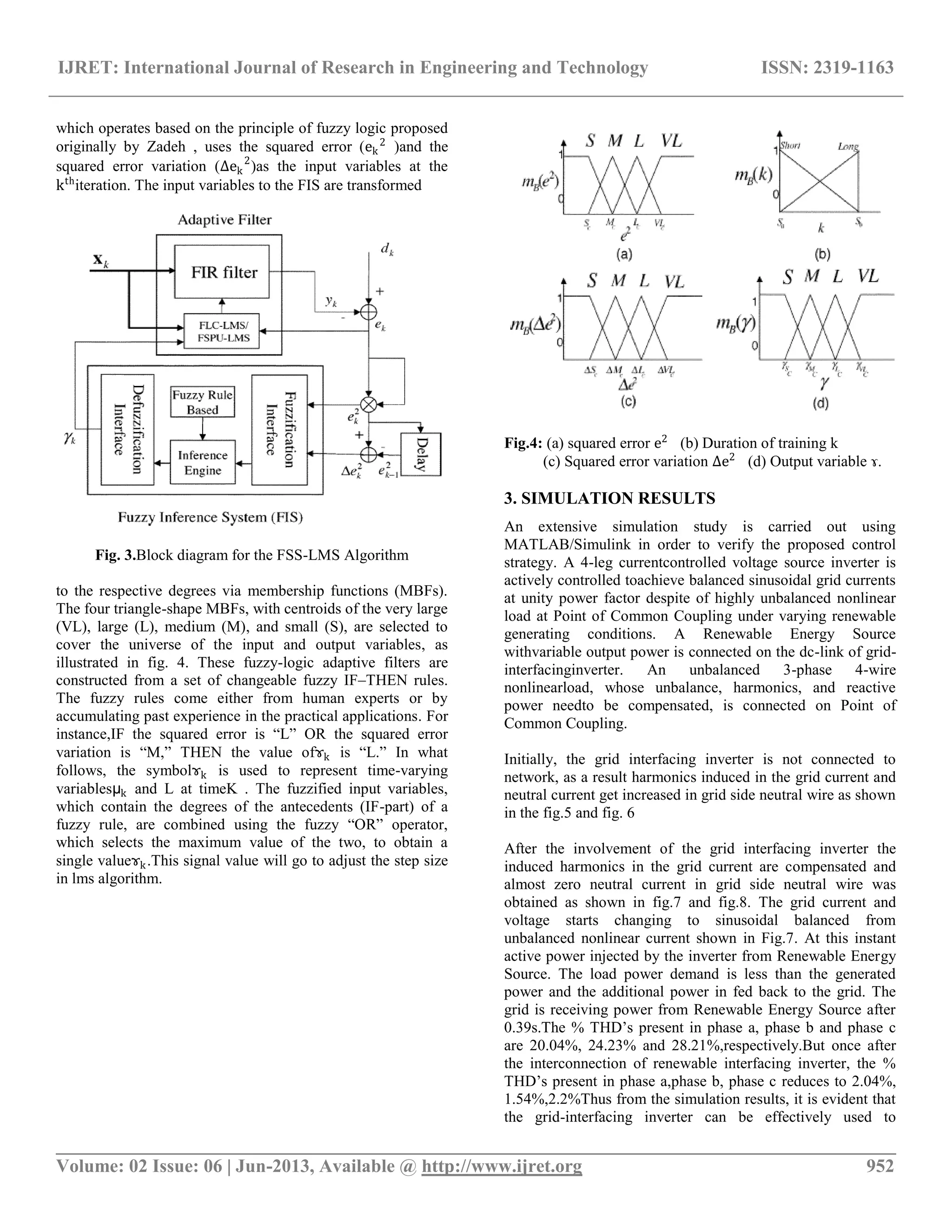
![IJRET: International Journal of Research in Engineering and Technology ISSN: 2319-1163 __________________________________________________________________________________________ Volume: 02 Issue: 06 | Jun-2013, Available @ http://www.ijret.org 951 The proposed system consists of RESconnected to the dc-link of a grid-interfacing inverter as shown in Fig. 1.It is possible to mitigate disturbances like voltage unbalance.It consists of a four-leg four-wire voltage source inverter .The voltage source inverter is a key element of a DG system as it interfaces the renewable energy source to the grid and delivers the generated power. The RES may be a AC source or an DC Source with rectifier coupled to dc-link. Usually the photovoltaic energy sources generate power at variable lowdc voltage, while the variable speed wind turbines generatepower at variable ac voltage. Thus, the power generated fromthese renewable sources needs power conditioning (i.e., dc/dcor ac/dc) before connecting on dc-link . The dc-capacitordecouples the RES from grid and also allows independentcontrol of converters on either side of dc-link. Fig 1.Renewable Based Distributed Generation system A.CONTROL STRATEGY Fig 2Control diagram of grid-interfacing inverter The fourth leg of inverter is used to compensate the neutral current of load. the inverter is actively controlled in such a way that it always draws/ supplies fundamental active powerfrom/ to the grid. If the load connected to the PCC is non-linear or unbalanced of both the given control approach also compensates the harmonics neutral current unbalance. The duty ratio of inverter switches are varied in a power cycle such that the combination of inverter and load injected power appears as balanced resistive load to the grid. The regulation of dc-link voltage carries the information regarding the exchange of active power in between renewable source and grid. The error between actual dc-link voltage (Vdc) and reference dc-link voltage (Vdc*) is given to the FSS-LMS Algorithm and the same error is used to update the weights. The output of FSS-LMS algorithm is further modified by subtracting the renewable injected current (iRen). This results in to the reference d-axis current (id*), while the reference q- axis current(iq*) is set to zero for unit power factor grid operation. The grid synchronizing angle (�) obtained from phase lock loop (PLL) is used to generate the reference grid currents (ia*, ib*, and ic*). The reference grid neutral current (in*) is set to zero to achieve balanced grid current operation. The hysteresis current controller is utilized to force the actual grid currents to trackthe reference grid currents accurately. This enables the grid to supply/absorb only the fundamental active power,while the RES interfacing inverter fulfills the unbalance, reactive and non-linear current requirements of 3- phase 4-wire load at PCC. B.DESIGN OF FSS-LMS ADAPTATION Adaptive finite impulse response (FIR) digital filters with the use of the least-mean-square(LMS) adaptation algorithm have been extensively applied to array signal processing for wireless communications. A key parameter to the design of the LMS-based filters is the step size, which governs the steady-state performance and the convergence characteristic of such filters. The conventional LMS algorithm usually utilizes a constant step size to update its filter tap weights in response to the changing environment. In general, a large step size leads to rapid convergence but results in large steady-state misadjustment error. The opposite phenomena occur when a small step size is employed. Variable step size methods have been reported to improve the convergence speedwhile preserving the steady state performance with a low increase of computational complexity [13]. Furthermore, variable step size methods have better tracking capacity in non-stationary environments than that of conventional LMS. All the variable step size methods adjust the step size by exploiting some linguistic rules of step size adjustment translated into numerical formulae of mathematical model. Therefore, with the aid of ICs, these linguistic rules in a mathematic model can be directly applying the fuzzy technique in the linguistic model. In this work, the proposed approach examined an alternative fuzzy variable definition in which the definition of step size depends on the mean square error (MSE). The FIS in Fig. 3,](https://image.slidesharecdn.com/powerqualityimprovementofgridinterconnecteddistributionsystemusingfss-lmsalgorithm-160802075628/75/Power-quality-improvement-of-grid-interconnected-distribution-system-using-fss-lms-algorithm-2-2048.jpg)
![IJRET: International Journal of Research in Engineering and Technology ISSN: 2319-1163 __________________________________________________________________________________________ Volume: 02 Issue: 06 | Jun-2013, Available @ http://www.ijret.org 953 compensate the load reactive power, current unbalance and current harmonics in addition to active power injection from Renewable energy source.This enables the grid to supply/ receive sinusoidal and balanced power at Unity power factor. Fig5:Before Compensation of grid current and voltage Fig:6Before Compensation of neutral current Fig7: After compensation of grid current and voltage Fig8: After Compensation of. Neutral current Table1:Total harmonics distoration Grid curren t Before compensation After compensation PI ANFI S FSS- LMS PI ANFI S FSS- LMS Phase A 20.9% 20.4% 20.04 % 2.9 % 2.36% 2.04 % Phase B 25.23 % 23.5% 24.23 % 2.7 % 1.68% 1.54 % Phase C 29.01 % 28.56 % 28.21 % 2.7 % 3.65% 2.2% CONCLUSIONS In this work adaptive fuzzy step size least mean squarealgorithm is proposed for renewable Interfacing Inverter. The controller works satisfactory under the dynamic operating conditions. It has also been shown that the inverter is able to perform all the duties of shunt Active power filter, while maintaining the smooth bidirectional power flow simultaneously. The simulations results supported by experimental results are provided to validate the fact that the renewable interfacing inverter can act as multi-operation device in order to utilize its maximum rating. The load reactive power demand, current harmonics and current unbalance of an unbalanced non-linear load at Point of common coupling, are compensated effectively such that the grid side currents are always maintained. Moreover, the load neutral current is restricted to flow towards the grid side by supporting it locally from the forth leg of inverter. The experimental result obtained on the simulated data of a renewable interfacing inverter using adaptive FSS-LMS algorithm shows satisfactory performance under the dynamic operating conditions. REFERENCES [1]. J. M. Guerrero, L. G. de Vicuna, J. Matas, M. Castilla, and J. Miret,―A wireless controller to enhance dynamic performance of parallel inverters in distributed generation](https://image.slidesharecdn.com/powerqualityimprovementofgridinterconnecteddistributionsystemusingfss-lmsalgorithm-160802075628/75/Power-quality-improvement-of-grid-interconnected-distribution-system-using-fss-lms-algorithm-4-2048.jpg)
![IJRET: International Journal of Research in Engineering and Technology ISSN: 2319-1163 __________________________________________________________________________________________ Volume: 02 Issue: 06 | Jun-2013, Available @ http://www.ijret.org 954 systems,‖ IEEE Transaction. Power Electronics.,vol. 19, no. 5, pp. 1205–1213, Sep. 2004 [2]. F.Blaabjerg, R. Teodorescu, M. Liserre and A. V. Timbus, ―Overview of control and grid synchronization for distributed power generation systems,‖IEEE Transaction. Industrial. Electronics, vol. 53, no. 5, pp. 1398–1409, Oct. 2006. [3].J. Dai, D. Xu, and B. Wu, ―Implementation and performance of cooperative control of shunt active filters for harmonic damping throughout a power distribution system,‖ IEEE Transaction. Power Electronics.,vol. 24, no. 4, pp. 963– 972, Mar./Apr. 2006. [4]. J. M. Carrasco, L. G. Franquelo, J. T. Bialasiewicz, E. Galván, R. C. P. Guisado, M. Á. M. Prats, J. I. León, and N. M. Alfonso, ―Power- Electronic Systems for the Grid Integration of Renewable Energy Sources: A Survey,‖ IEEE Transaction. Industrial.Electronics., vol. 53, no. 4, pp. 1002– 1016, Aug. 2006. [5]. J. H. R. Enslin and P. J. M. Heskes, ―Harmonic interaction between a large number of distributed power inverters and the distribution network,‖IEEE Transaction. Power Electronics, vol. 19, no. 6, pp. 1586–1593, Nov. 2004 [6]. J. M. Guerrero, L. G. de Vicuna, J. Matas, M. Castilla, and J. Miret, ―A wireless controller to enhance dynamic performance of parallel in-verters in distributed generation systems,‖ IEEE Trans. Power Elec-tron., vol. 19, no. 5, pp. 1205–1213, Sep. 2004. [7]. J. H. R. Enslin and P. J. M. Heskes, ―Harmonic interaction between a large number of distributed power inverters and the distribution net-work,‖ IEEE Trans. Power Electron., vol. 19, no. 6, pp. 1586–1593, Nov. 2004. [8]. S. Rahmani, A. Hamadi, N. Mendalek, and K. Al-Haddad, ―A NewControl Technique for Three-Phase Shunt Hybrid Power Filter,‖ IEEETransaction. Industrial.Electronics. vol. 56, no. 8, pp. 2904–2915, Aug. 2009 [9].M. Singh and A. Chandra, ―Power maximization and voltage sag/swell ride-through capability of PMSG based variable speed wind energy conversion system,‖ in Process. IEEE 34th Annual Conference Industrial Electronics. Soc., 2008, pp. 2206–2211. [10].L.Yacoubi,K.Al-Haddad,L.A.Dessaint,andF.Fnaiech ―Linear and non.inear control techniques for a three-level NPC boost rectifier,‖IEEETrans.Ind.Electron., vol. 53, no. 6, pp.1908-1918, Dec.2006. [11].Rondineli Rodrigues Pereira, Carlos Henrique da Silva, Luiz Eduardo Borges da Silva, Germano Lambert-Torres, ―New strategies for application of adaptive filters in Active power filter,‖IEEETransation on Industry Applications, vol. 47. no.3, may/june 2012 [12].Hsuan-Yu Lin, Chia-Chang Hu, Yu-Fan Chen, and Jyh- Horng Wen, ―An Adaptive Robust LMS Employing fuzzy step size and partial update,‖IEEE signal processing letters, vol.12,no. 8, August 2008 [13]. W. S. Gan, ―Designing a fuzzy step size LMS algorithm,‖ IEEE Proc. Inst. Elect. Eng., Vision, Image, Signal Process., vol. 144, no. 5, pp. 261–266,Oct. 1997](https://image.slidesharecdn.com/powerqualityimprovementofgridinterconnecteddistributionsystemusingfss-lmsalgorithm-160802075628/75/Power-quality-improvement-of-grid-interconnected-distribution-system-using-fss-lms-algorithm-5-2048.jpg)

This document discusses the development of a fuzzy step size least mean square (FSS-LMS) algorithm aimed at improving power quality in grid-interconnected distribution systems with renewable energy sources. The proposed algorithm addresses the challenges posed by nonlinear loads and harmonics, ensuring balanced grid currents and efficient energy injection from renewable sources. Simulation results demonstrate that the FSS-LMS algorithm can effectively mitigate current imbalances and harmonics, achieving a unity power factor and improving overall grid performance.