Downloaded 2,072 times


The document discusses different types of programming languages used in programmable logic controllers (PLCs), including ladder logic, Boolean logic, and Grafcet. It provides details on each language and describes common instruction sets used, such as timers, counters, arithmetic, and data manipulation. The document also covers IEC 61131-3 standard languages like ladder diagrams, function block diagrams, instruction lists, structured text, and sequential function charts. Finally, it discusses PLC architecture and different I/O bus network standards and configurations.
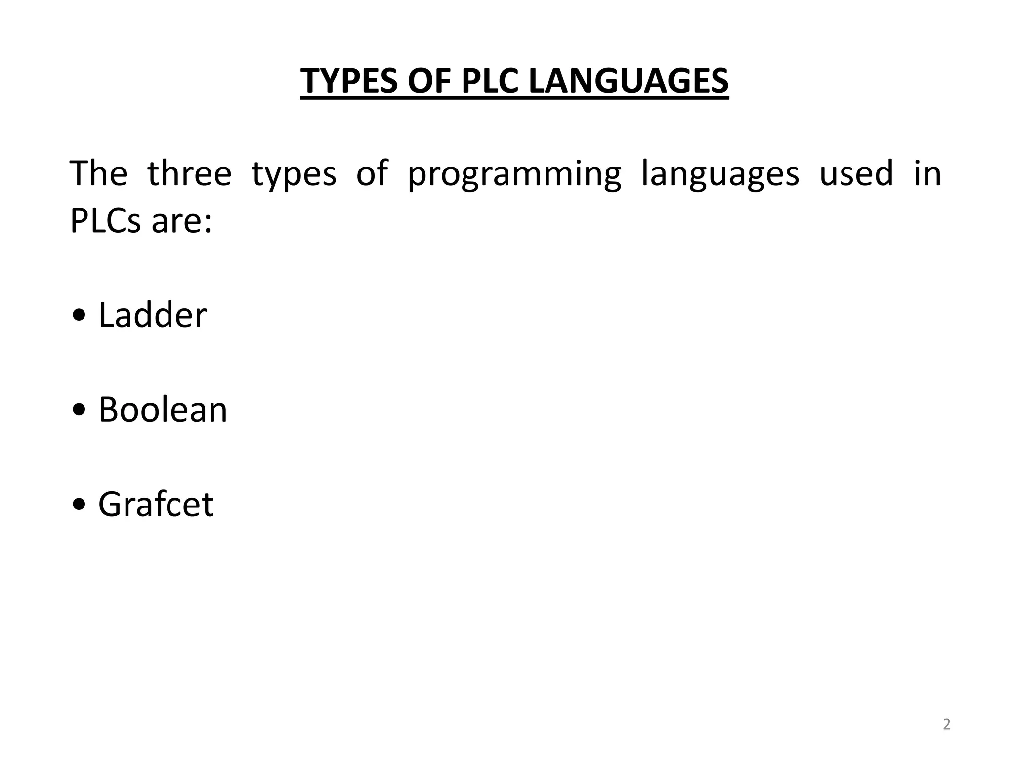
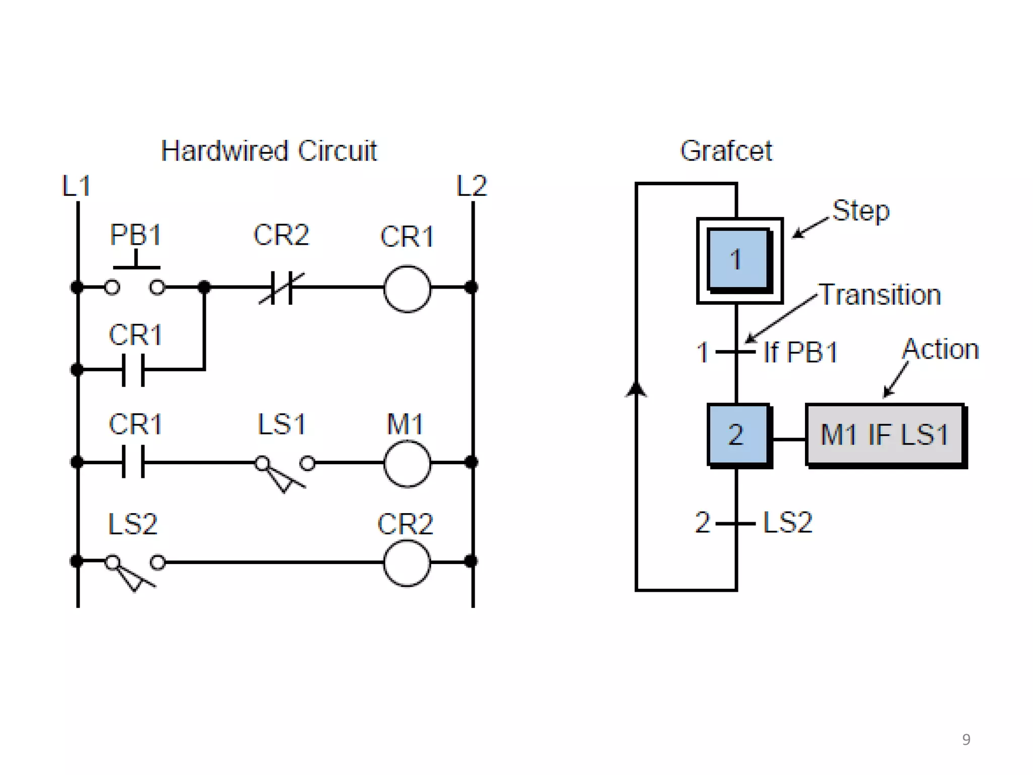
Introduction to PLCs, highlighting three programming languages: Ladder, Boolean, and Grafcet.
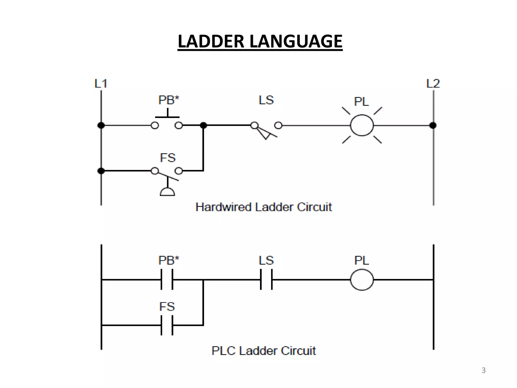
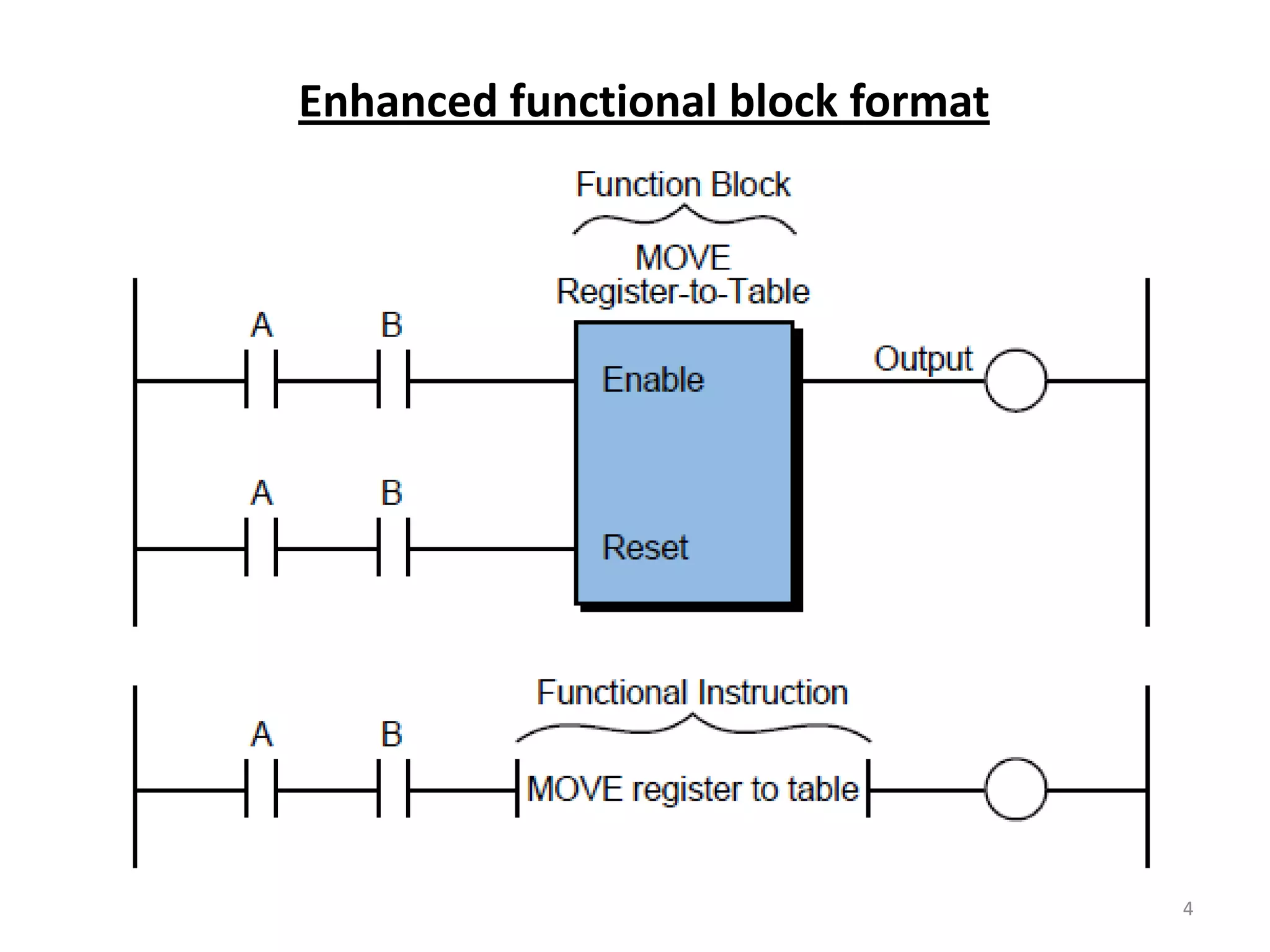
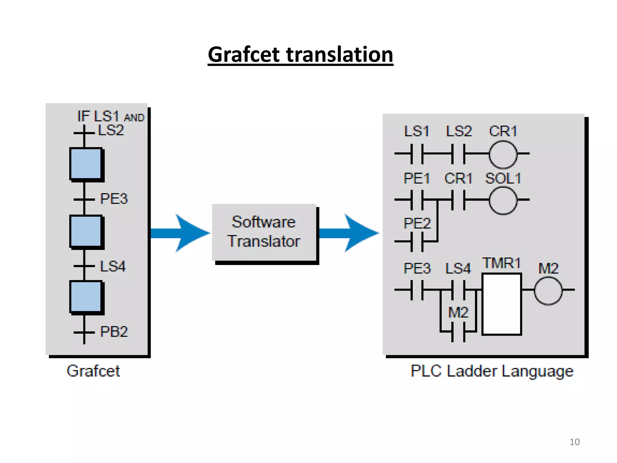
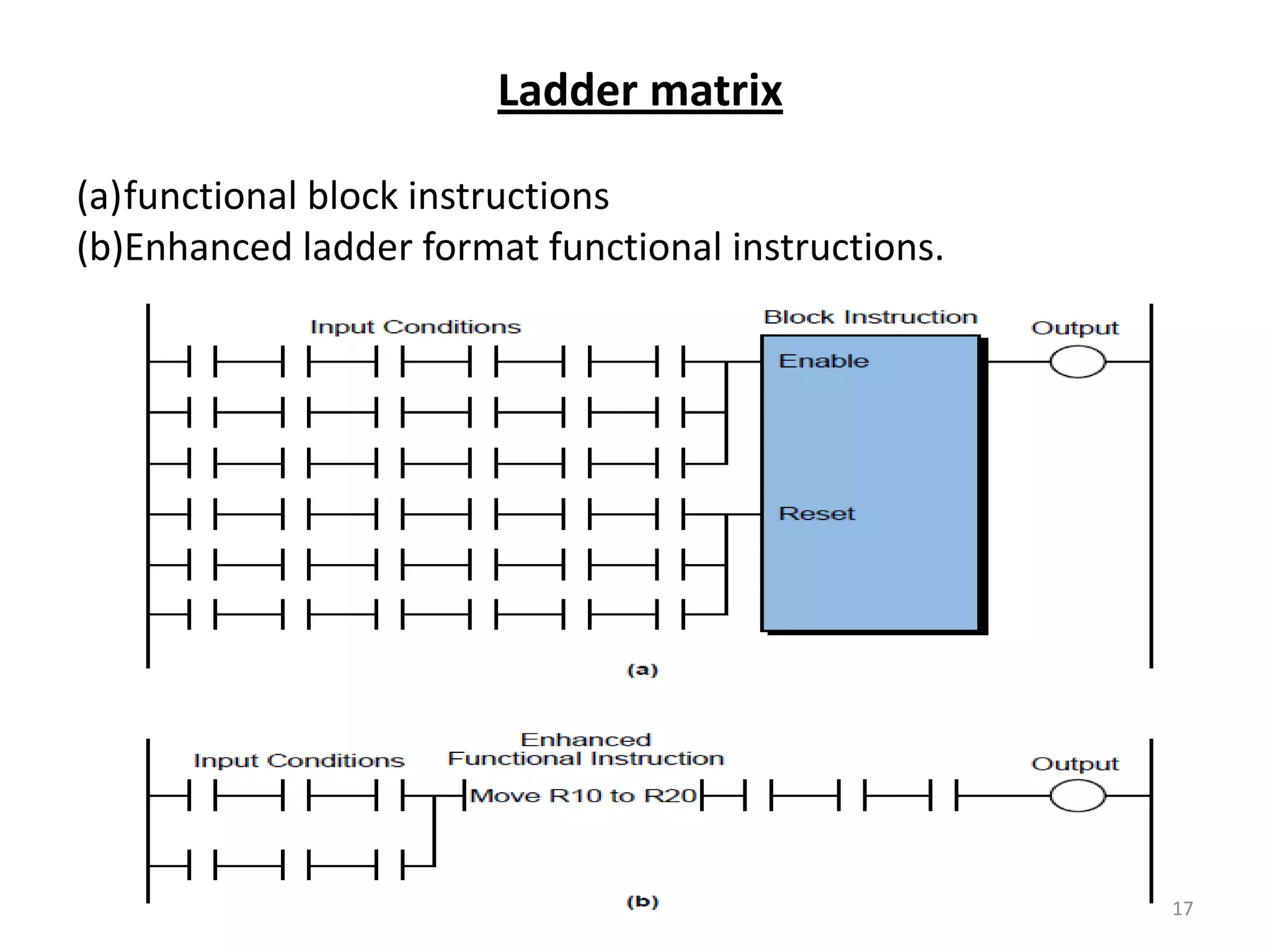
Details on Ladder language, enhanced functional format, and Grafcet, with a focus on graphical representation.
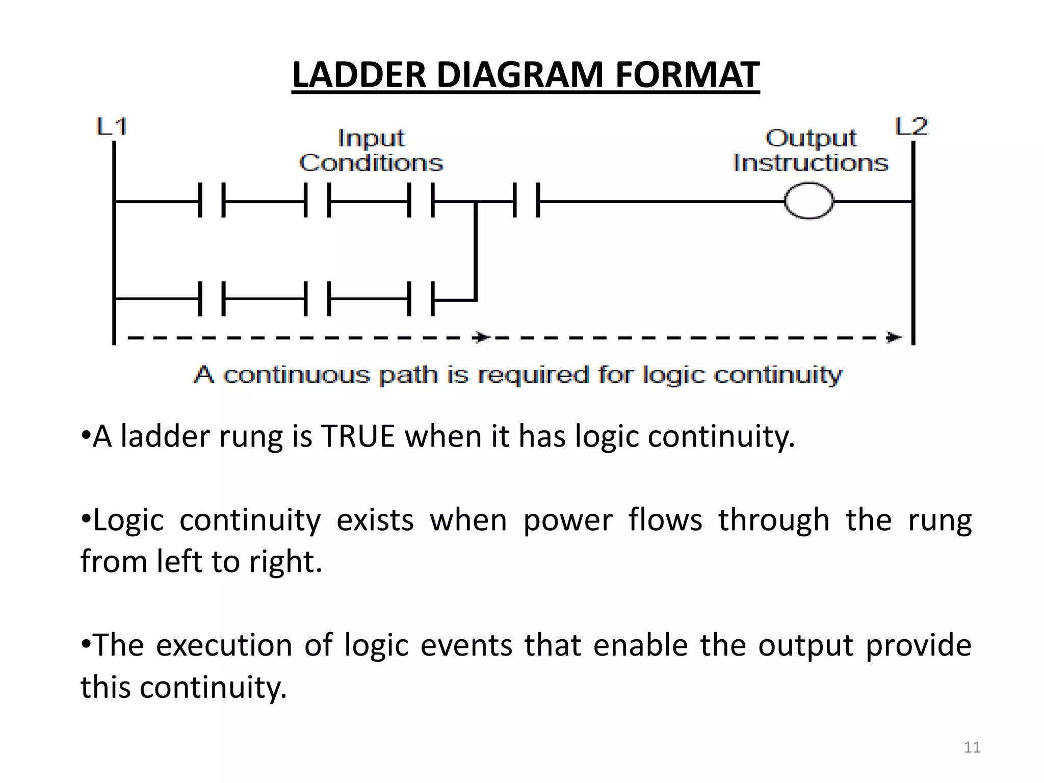
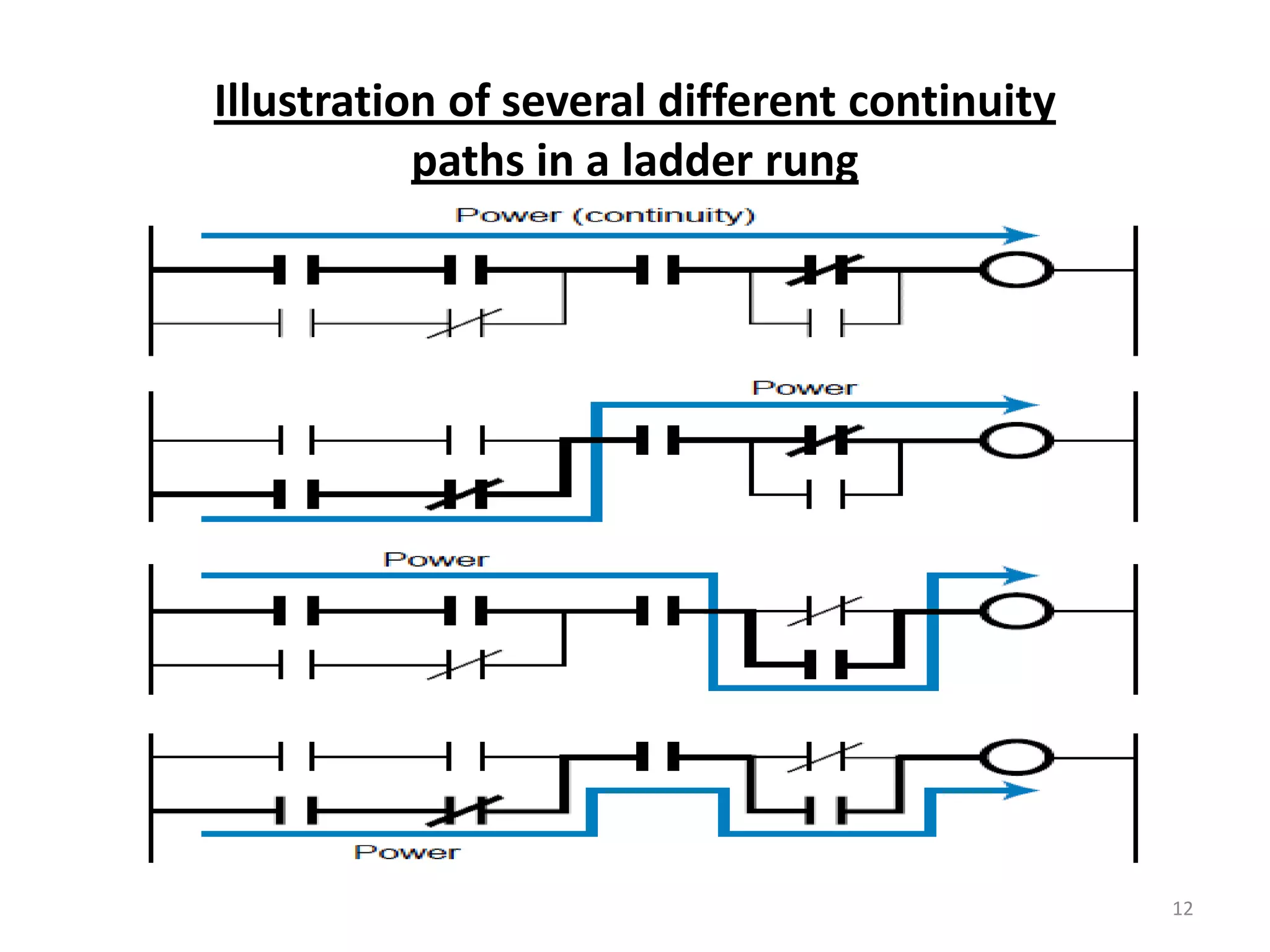
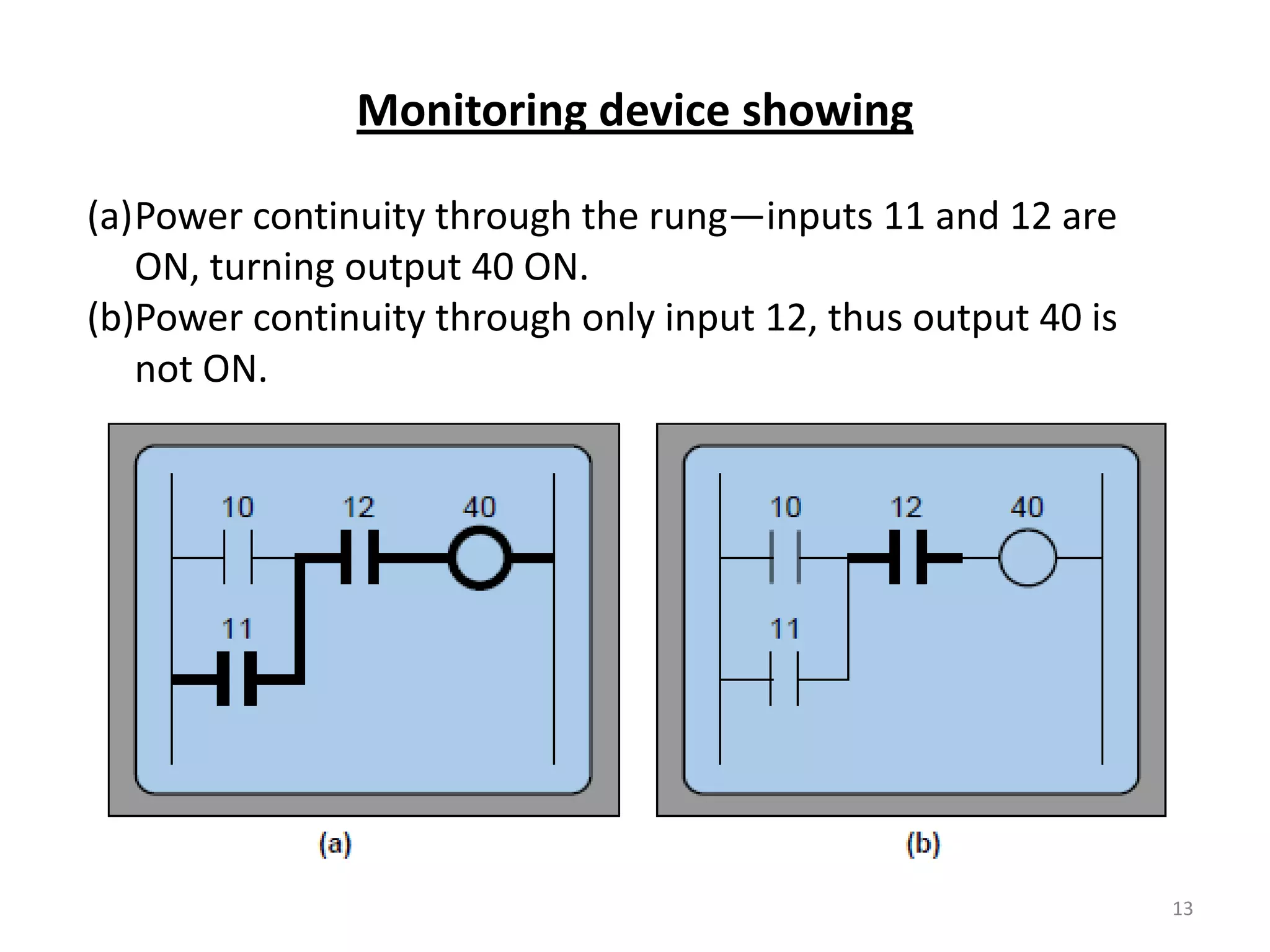
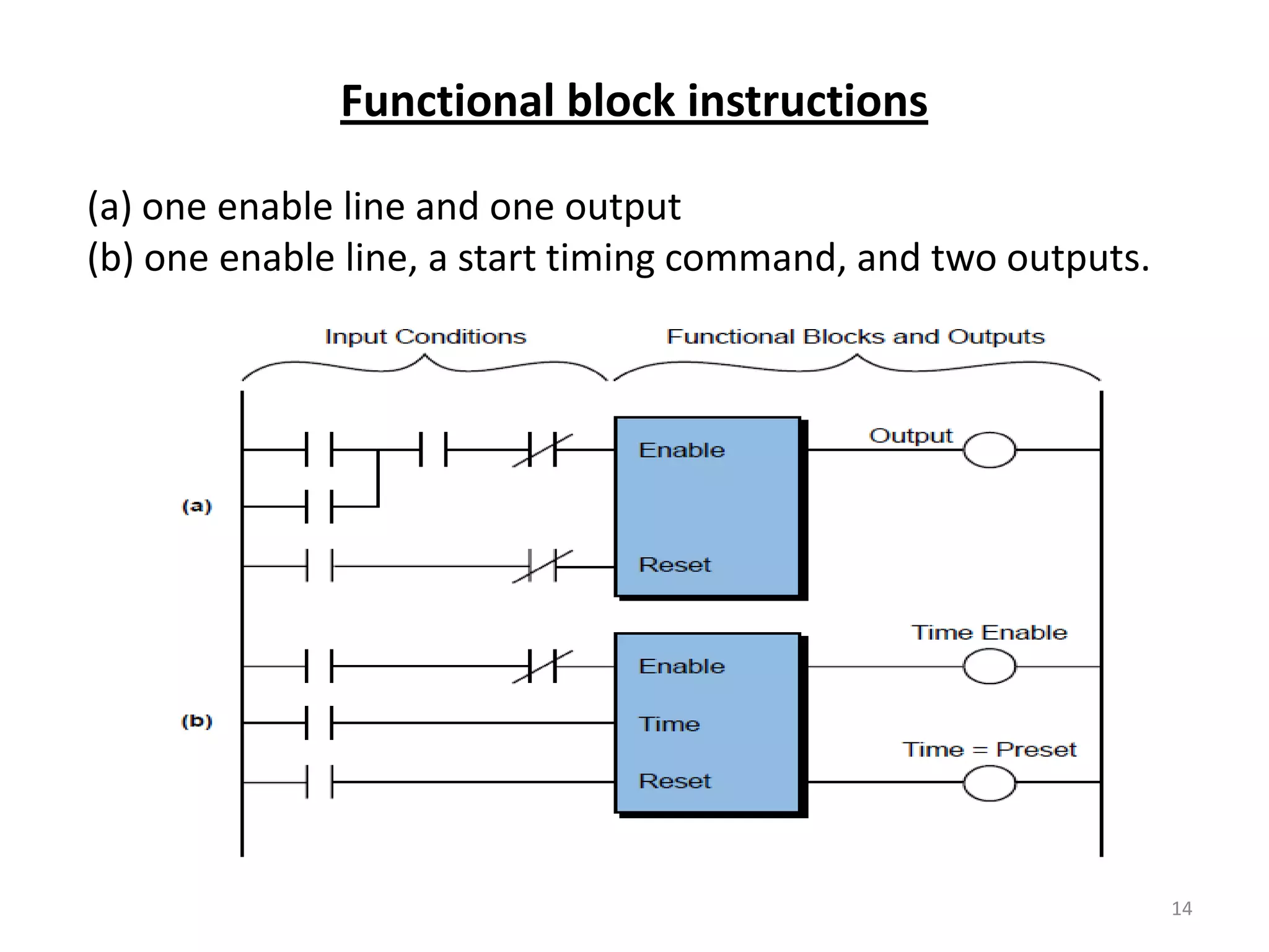
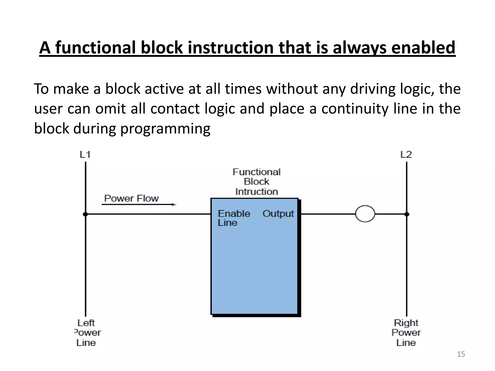
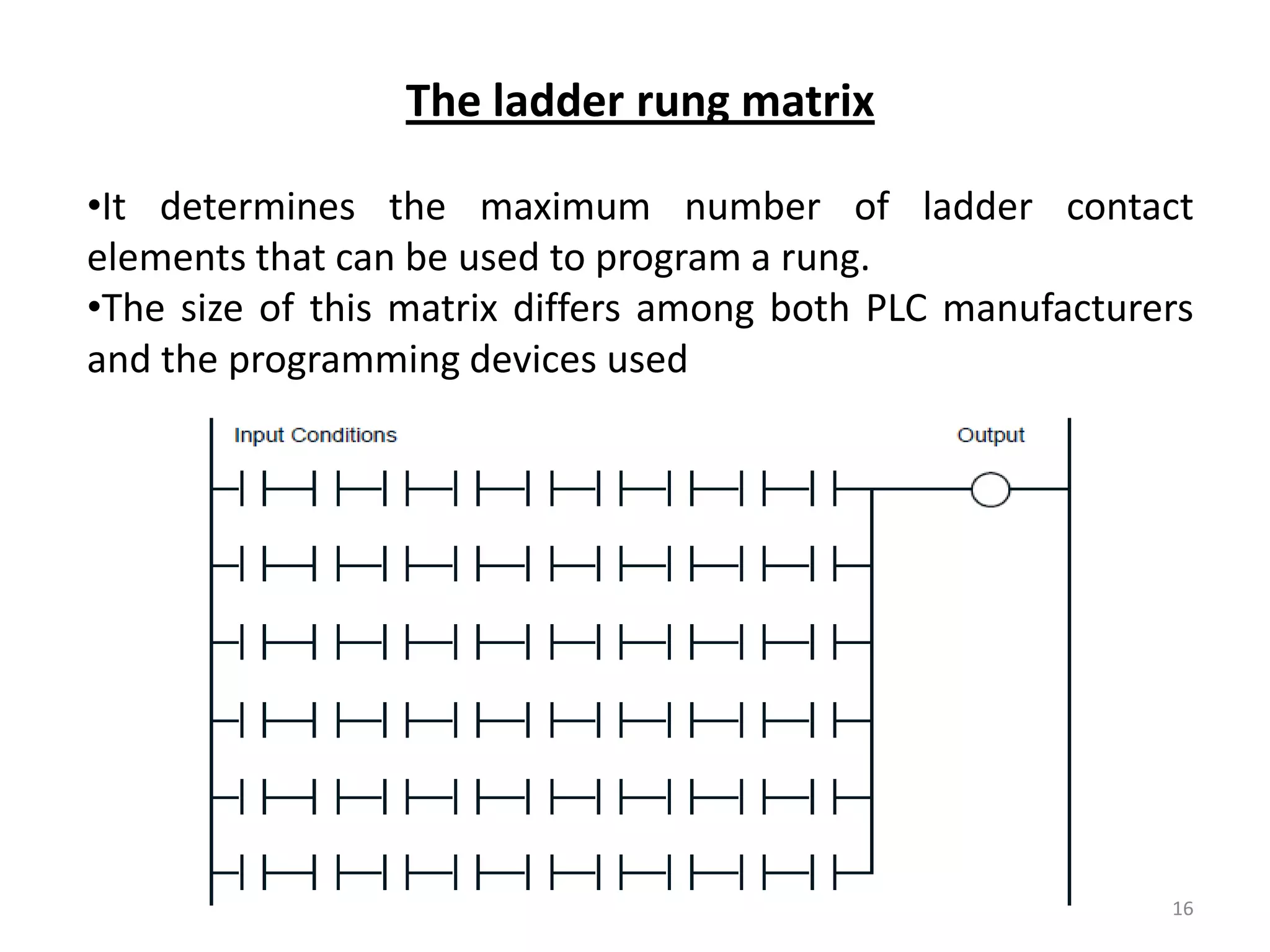
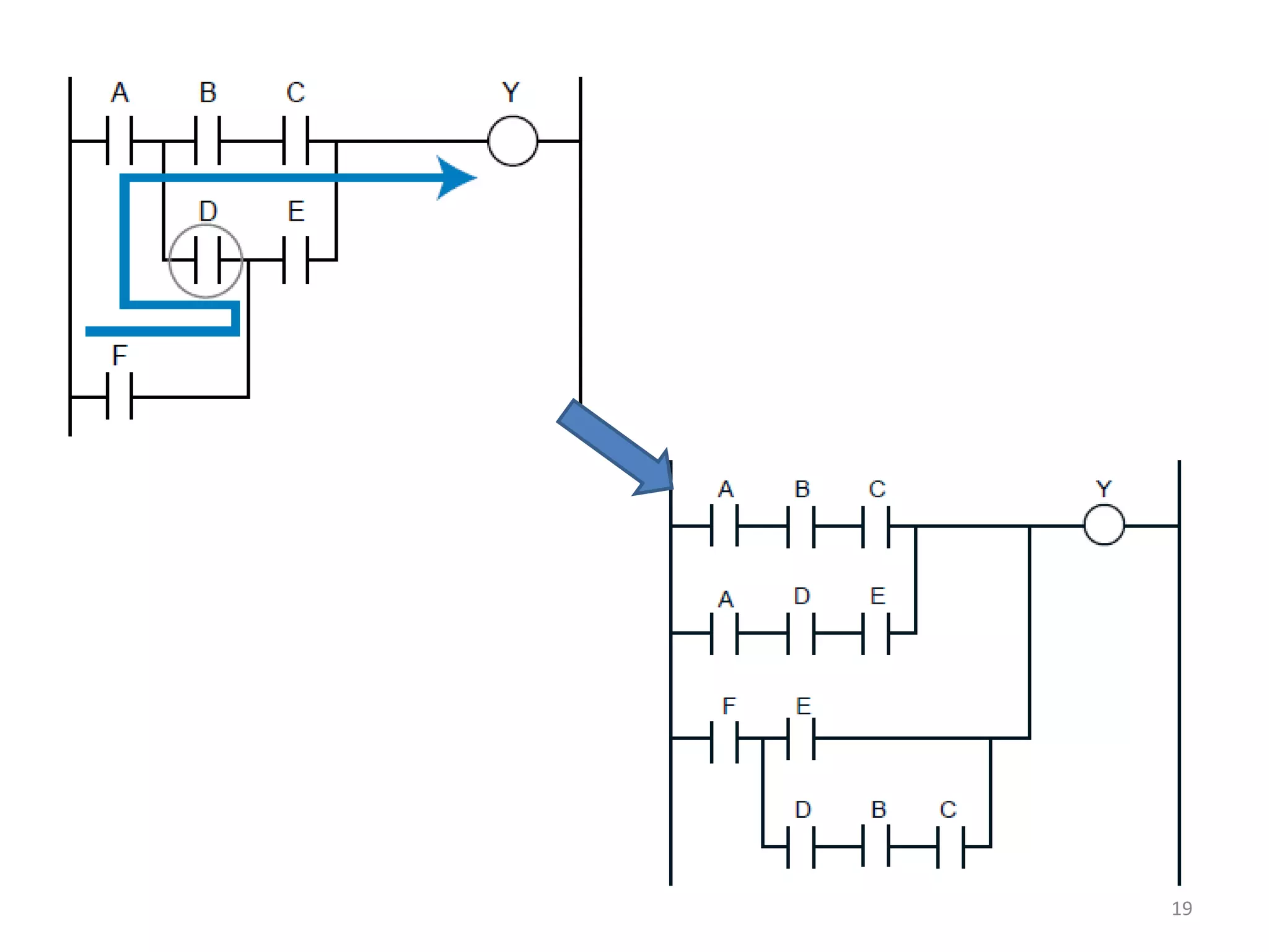
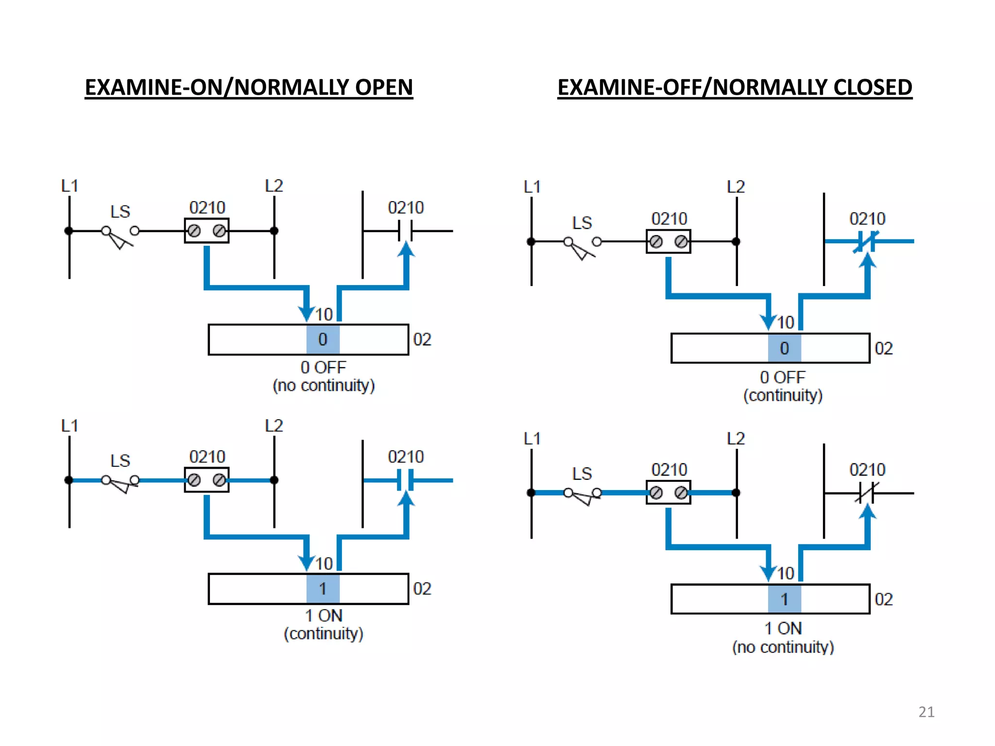
Explains ladder diagram format, continuity concepts, monitoring devices, and power flow rules in ladder programming.
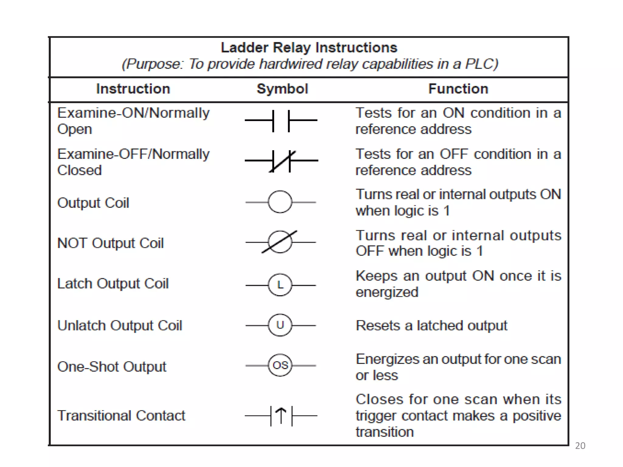
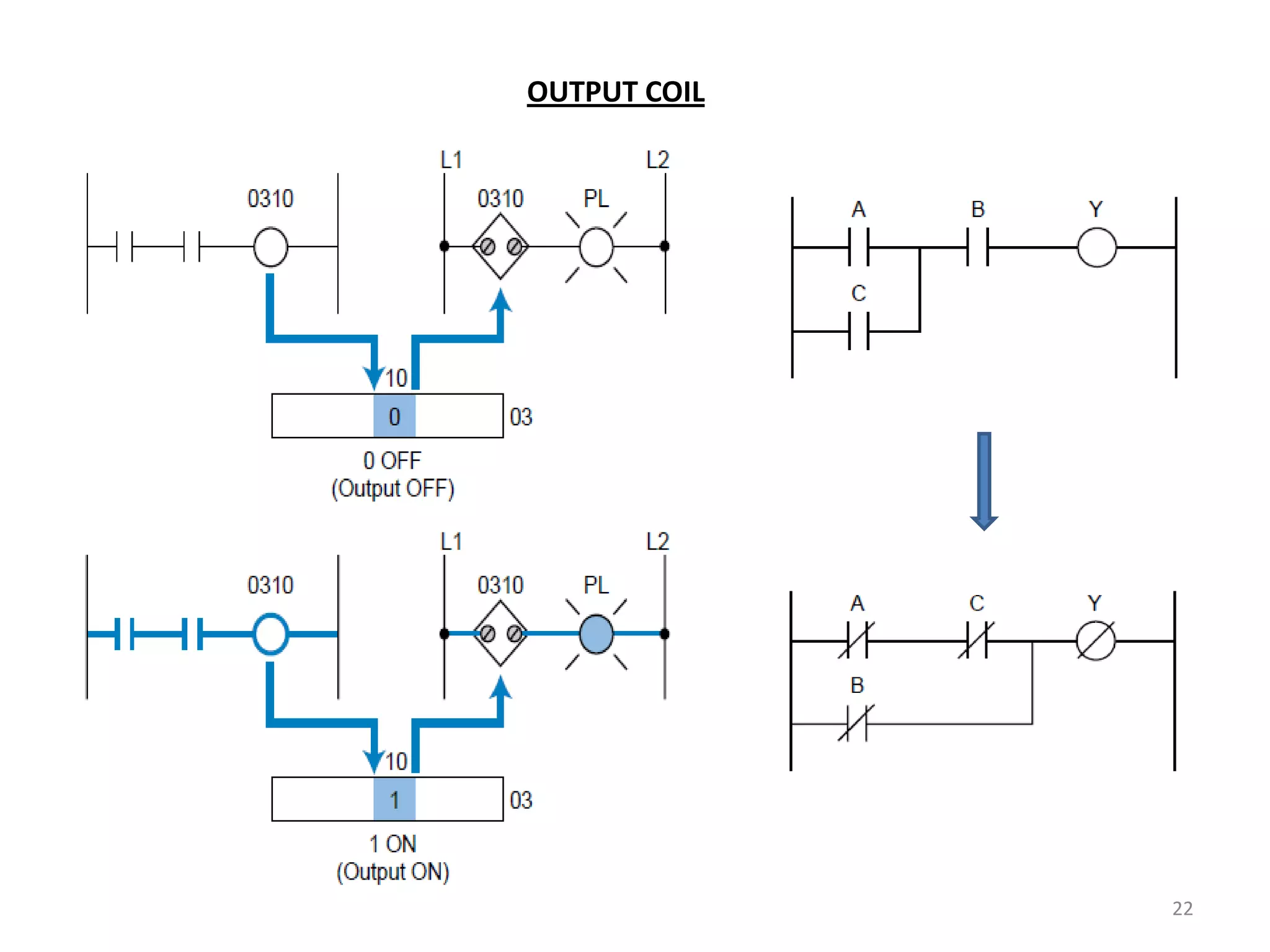
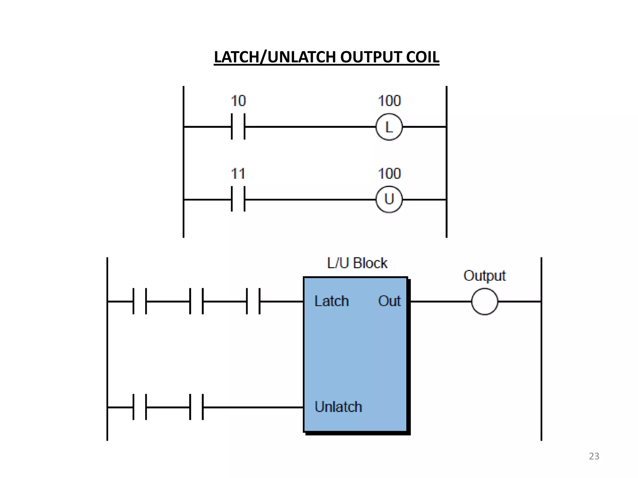
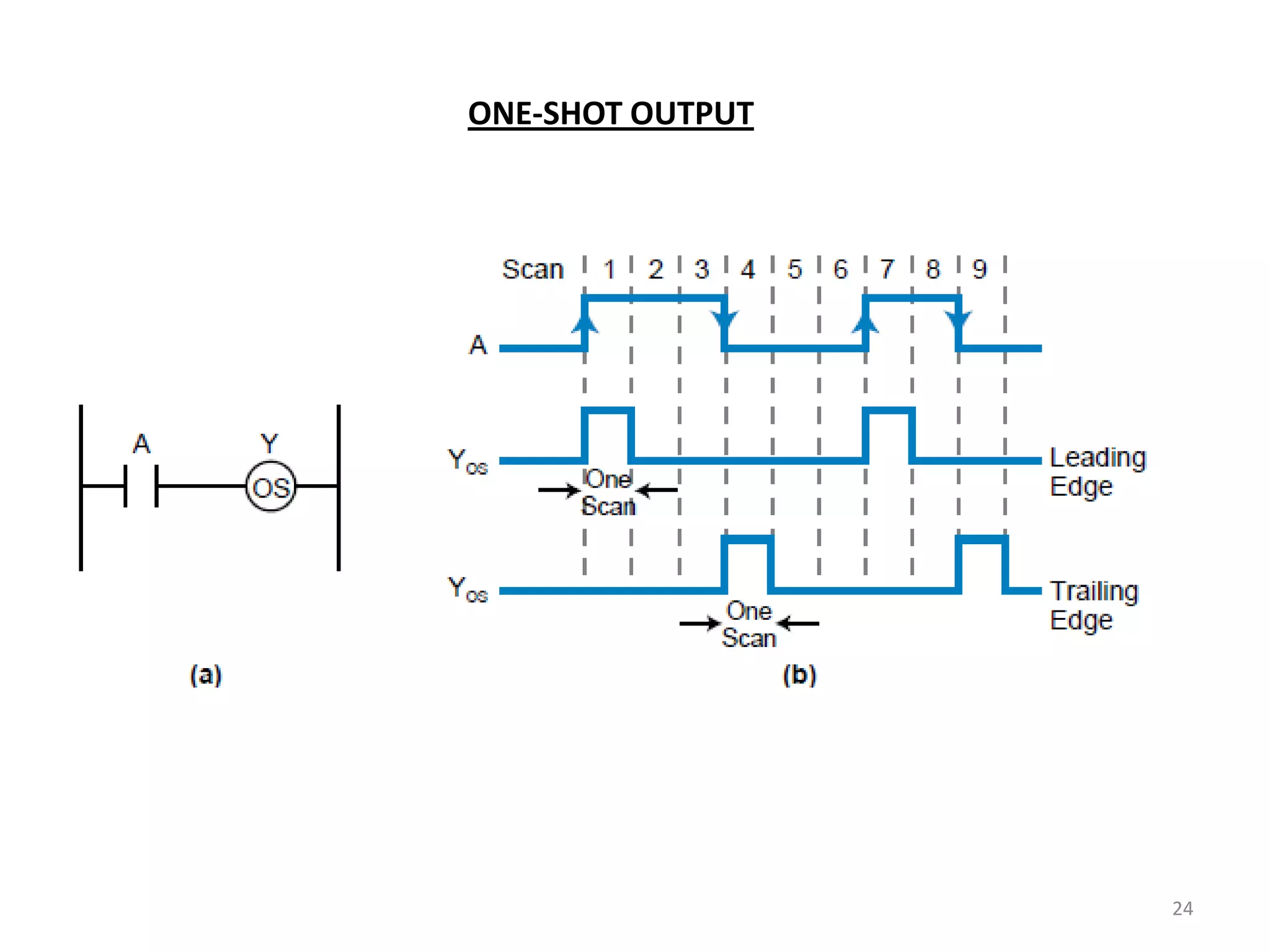
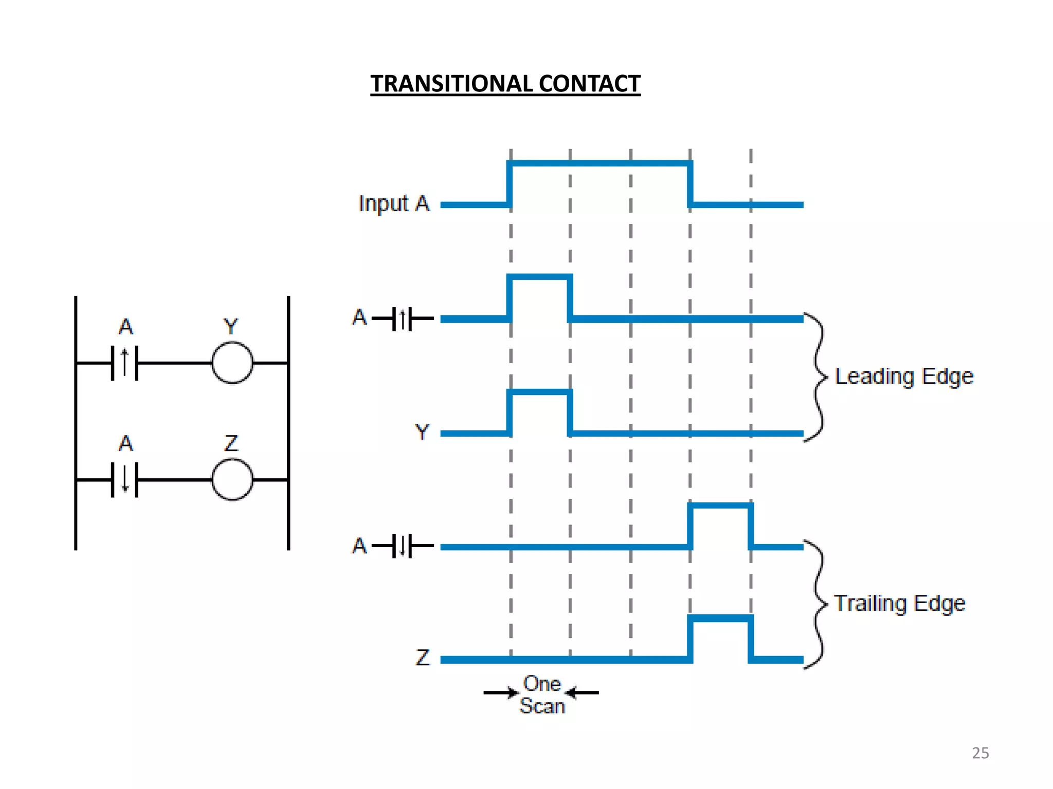
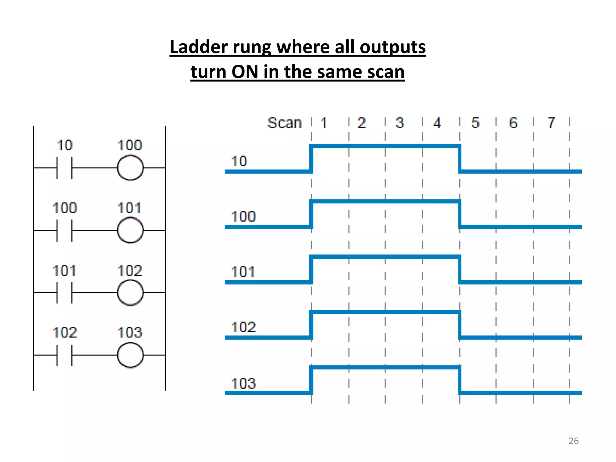
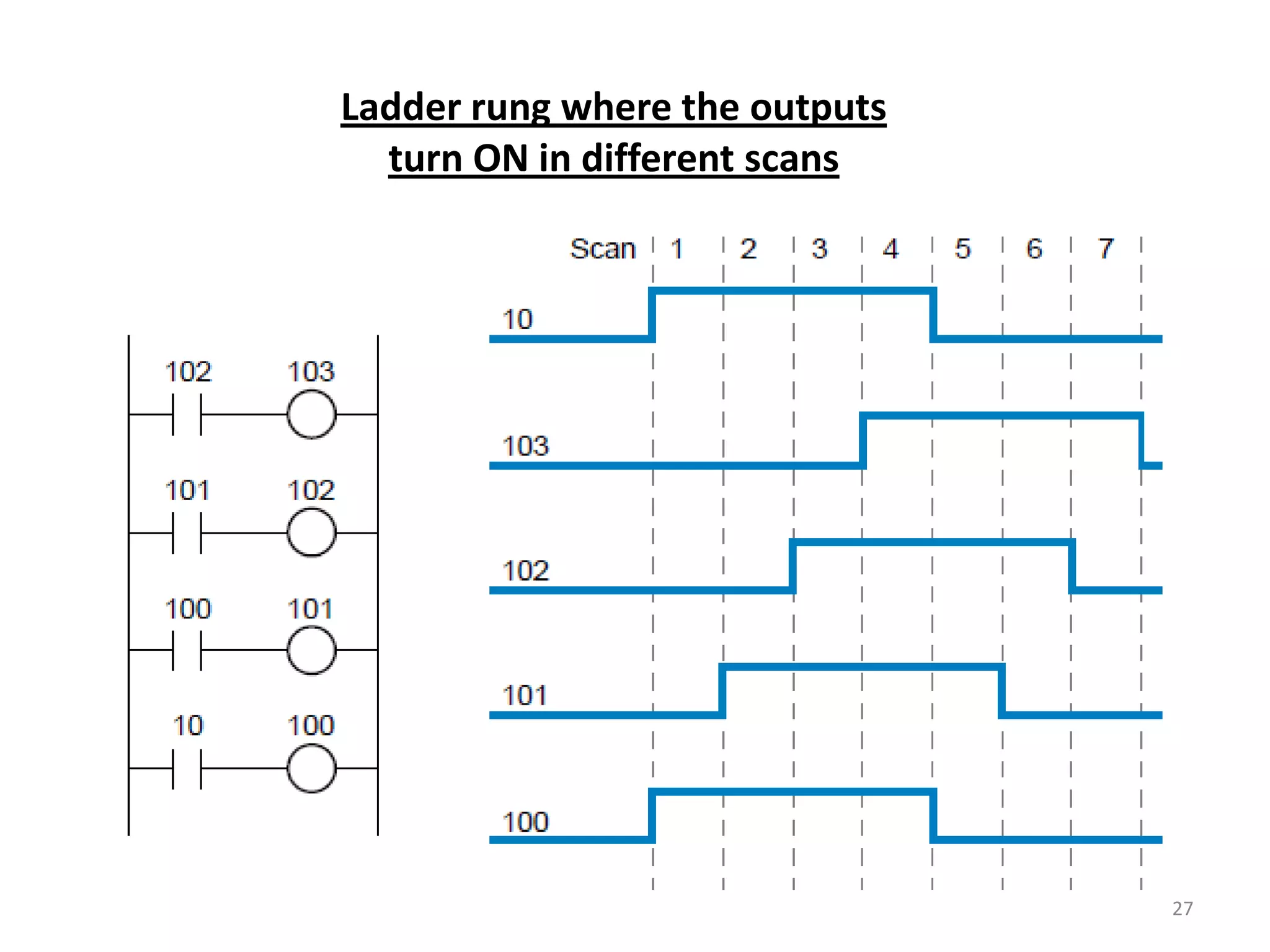
Details on logical output controls such as examine-on, output coils, and behavior during scans.
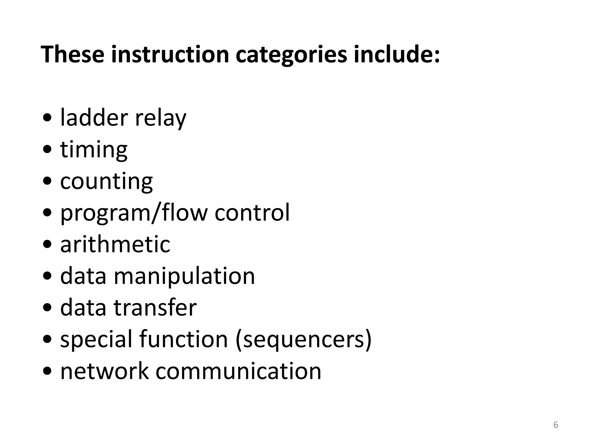
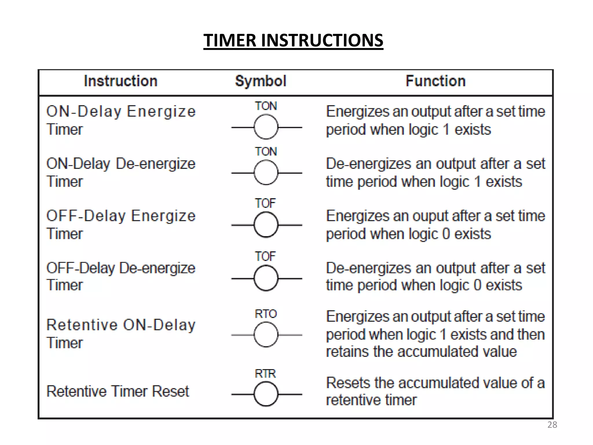
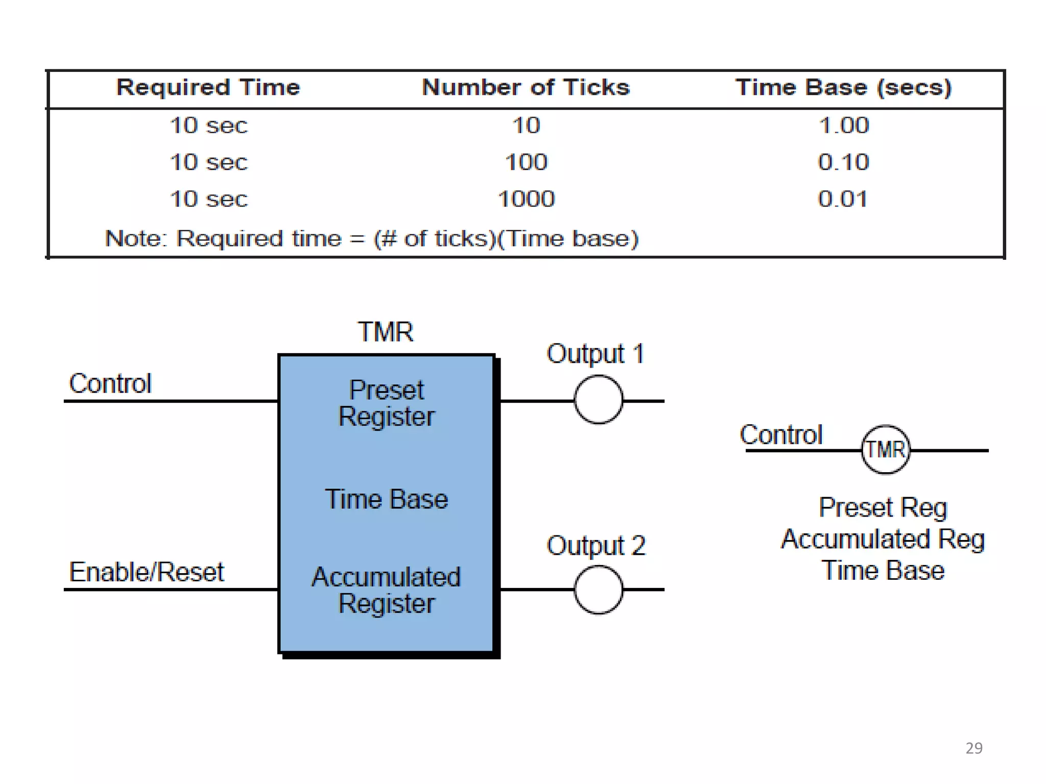
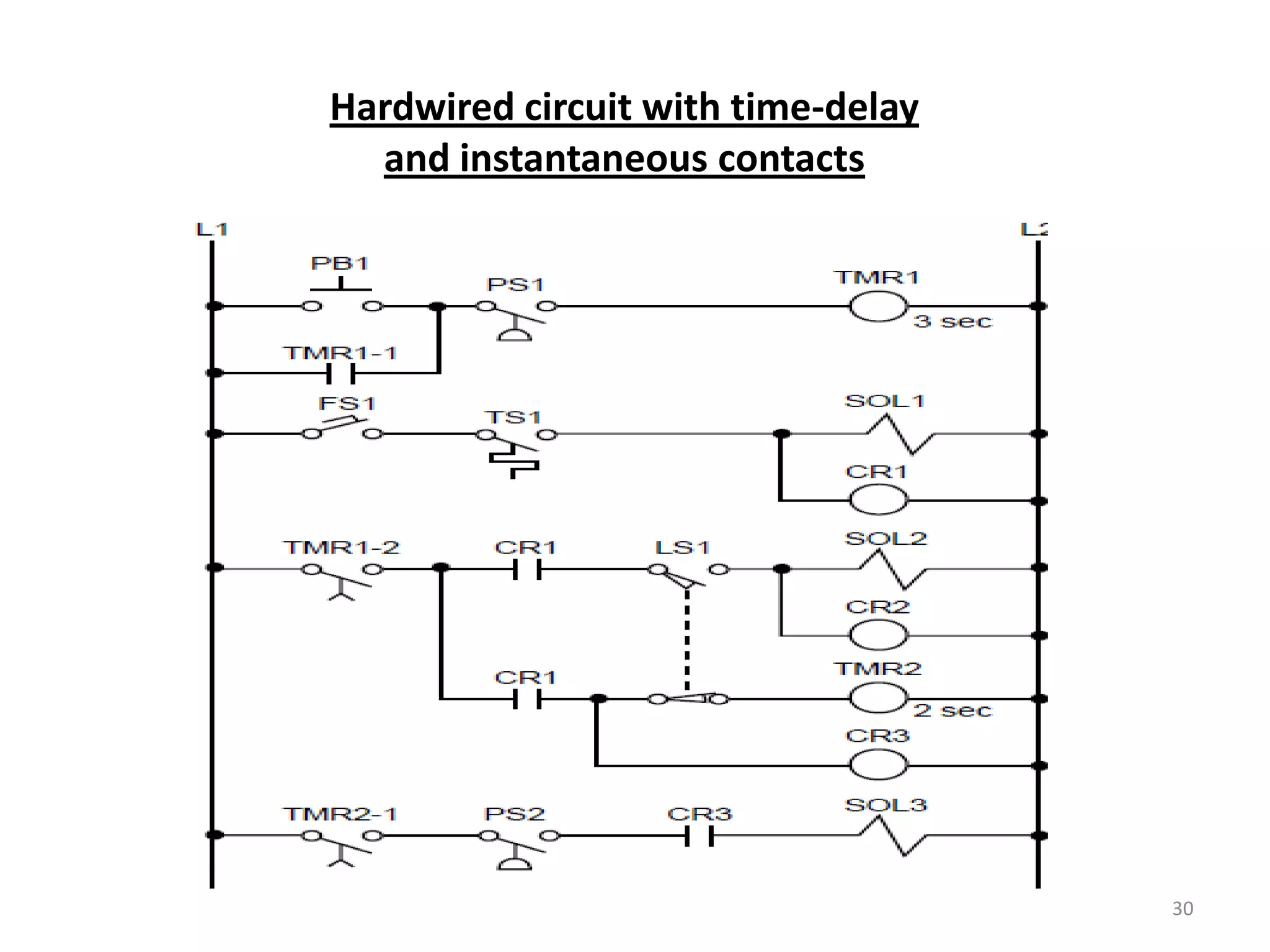
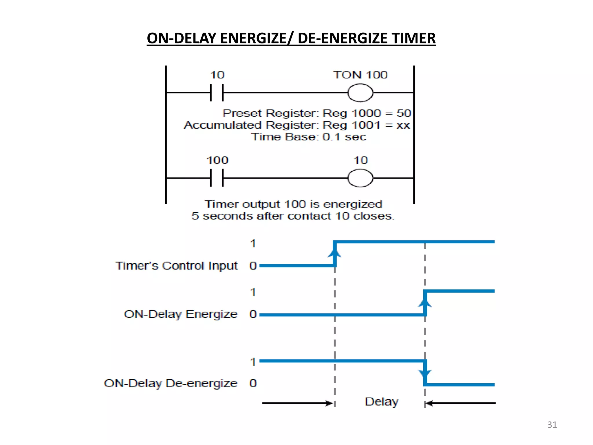
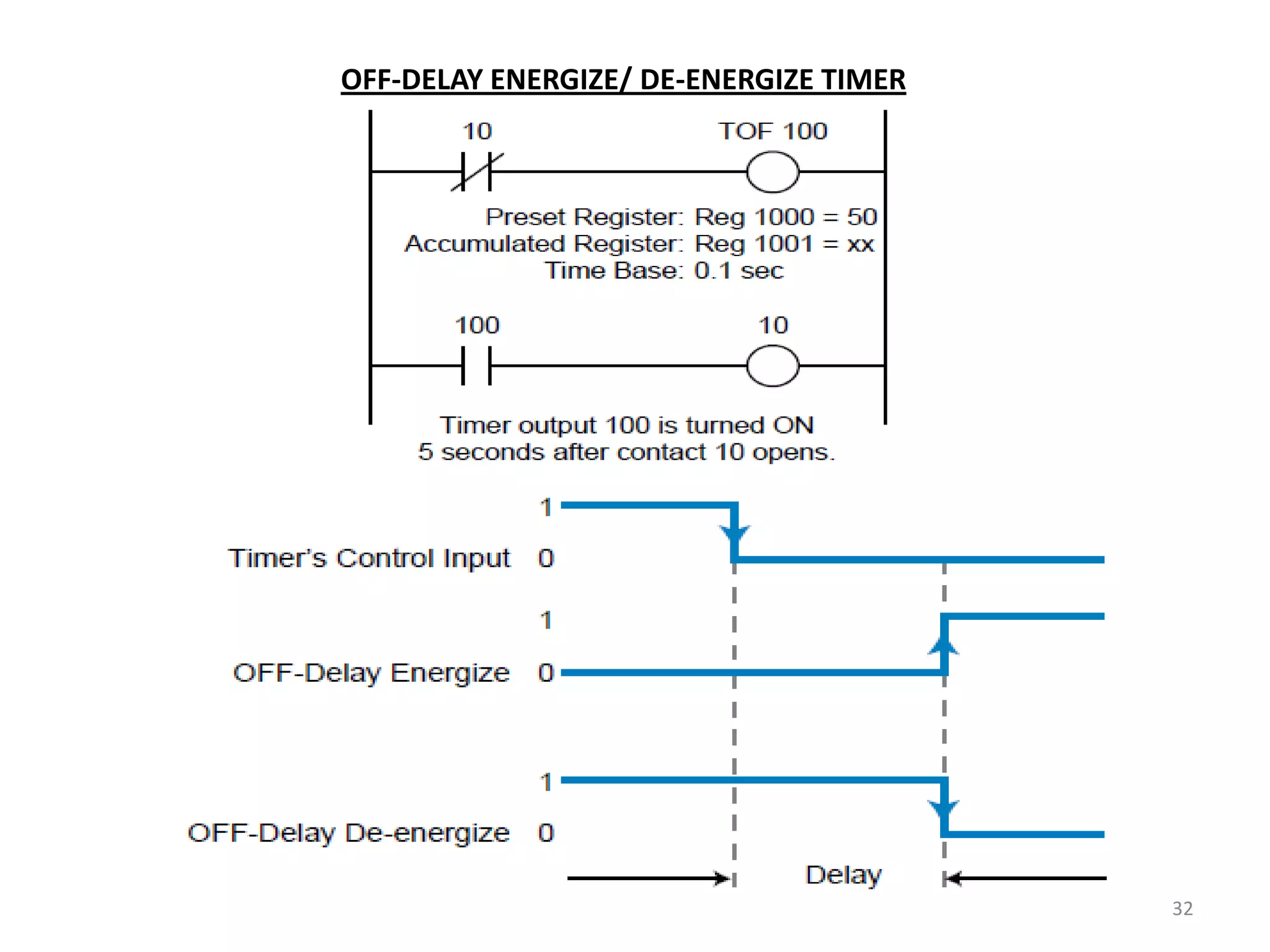
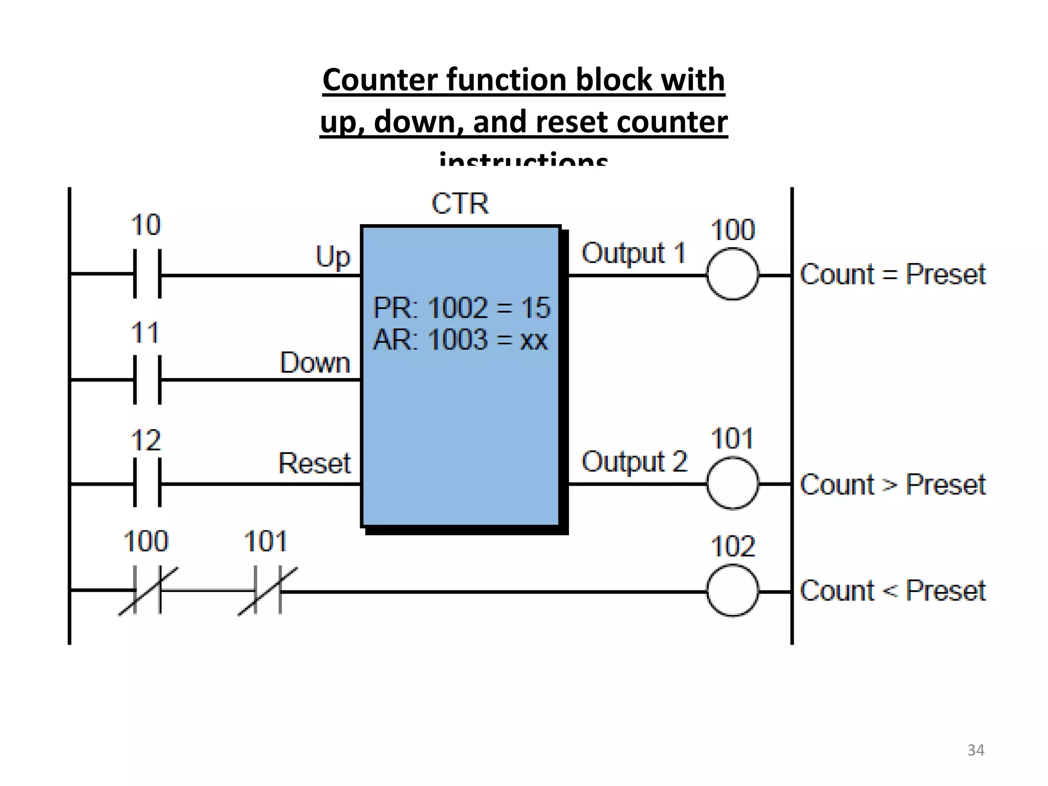
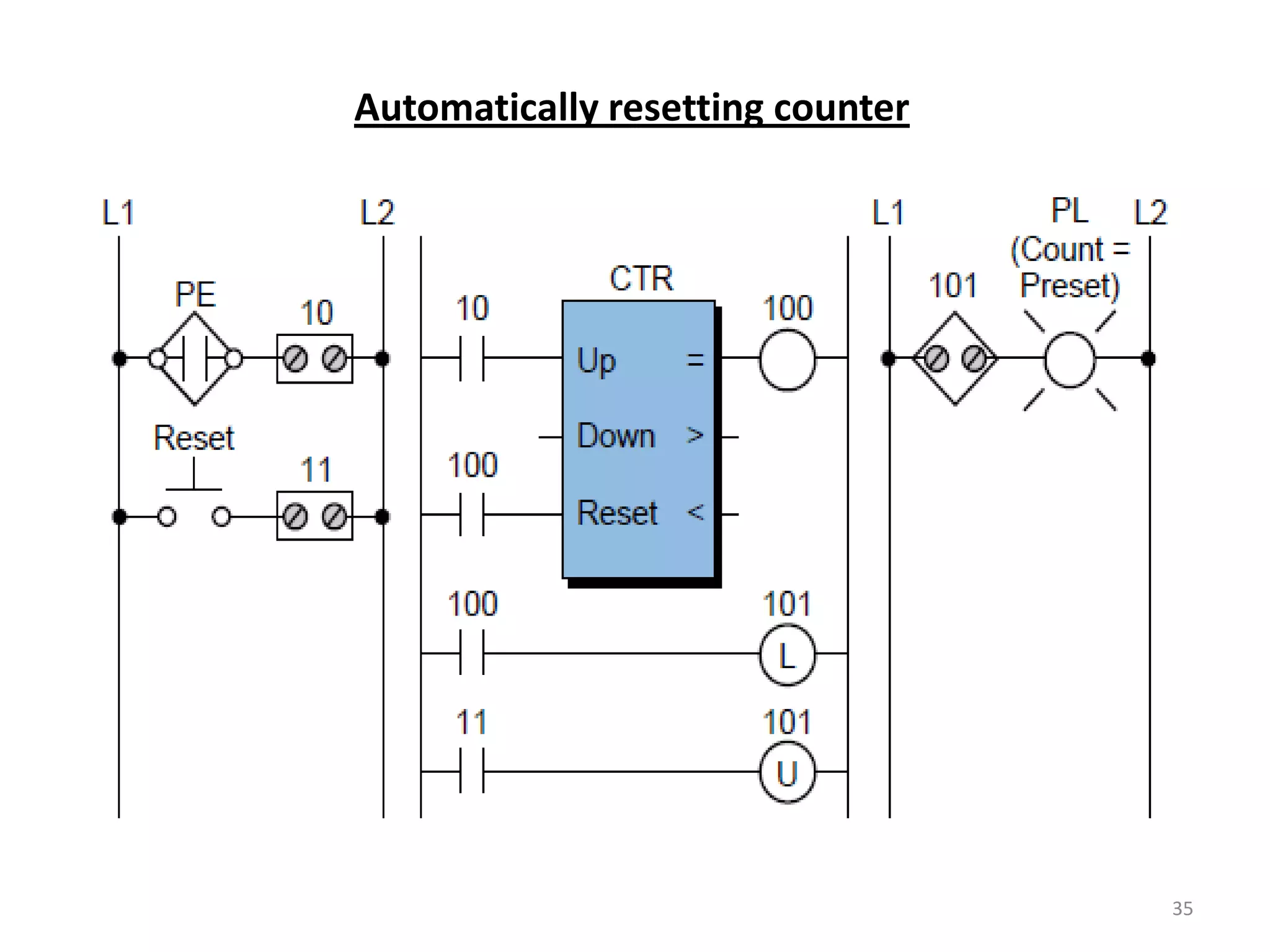
Overview of timer and counter instructions including ON/OFF delays and resetting mechanisms.
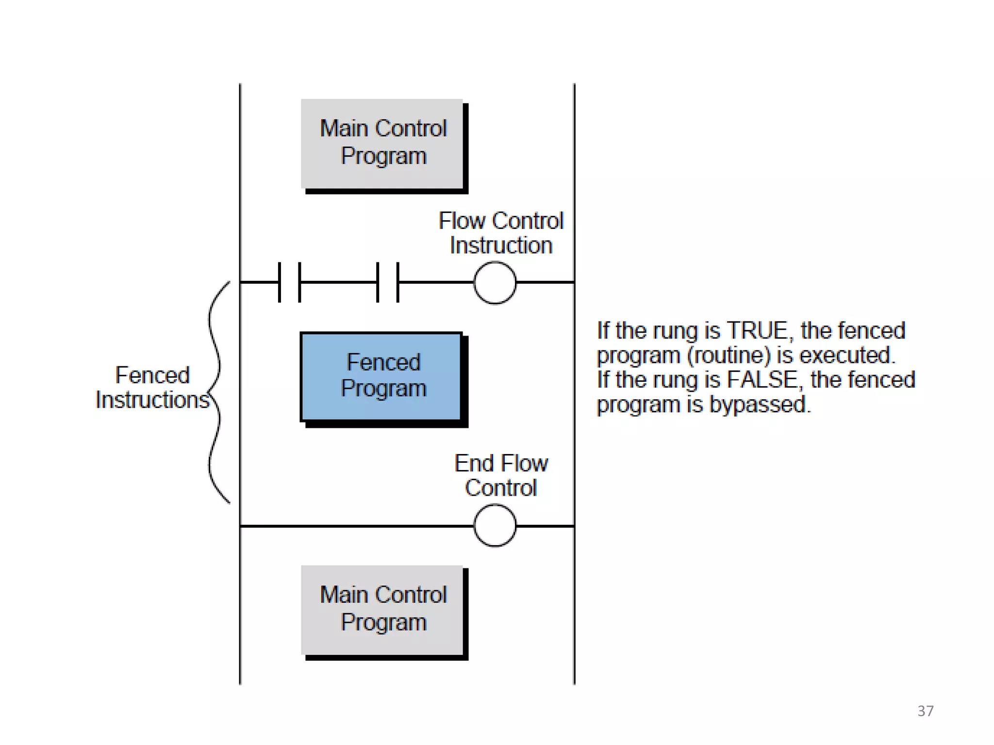
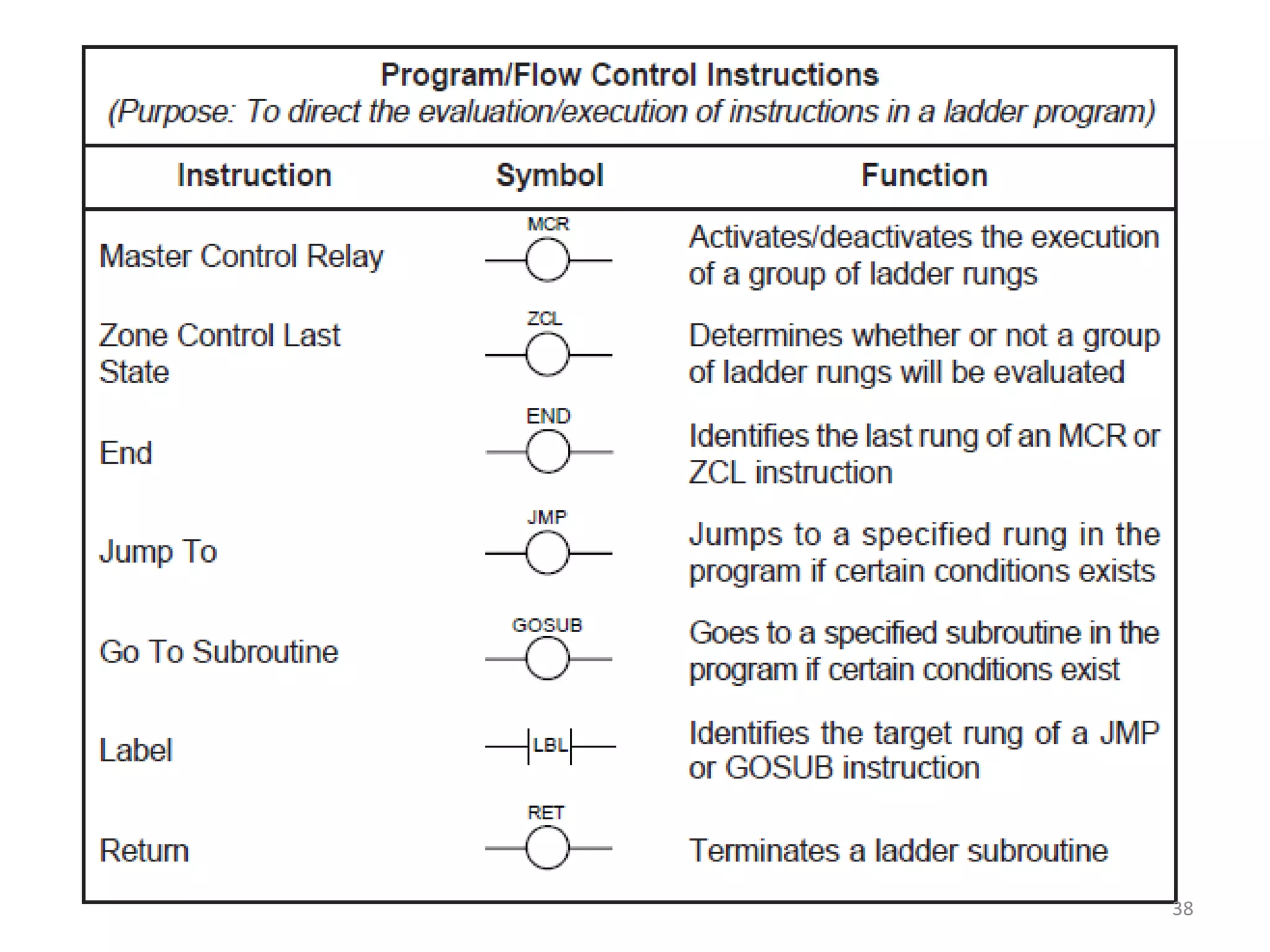
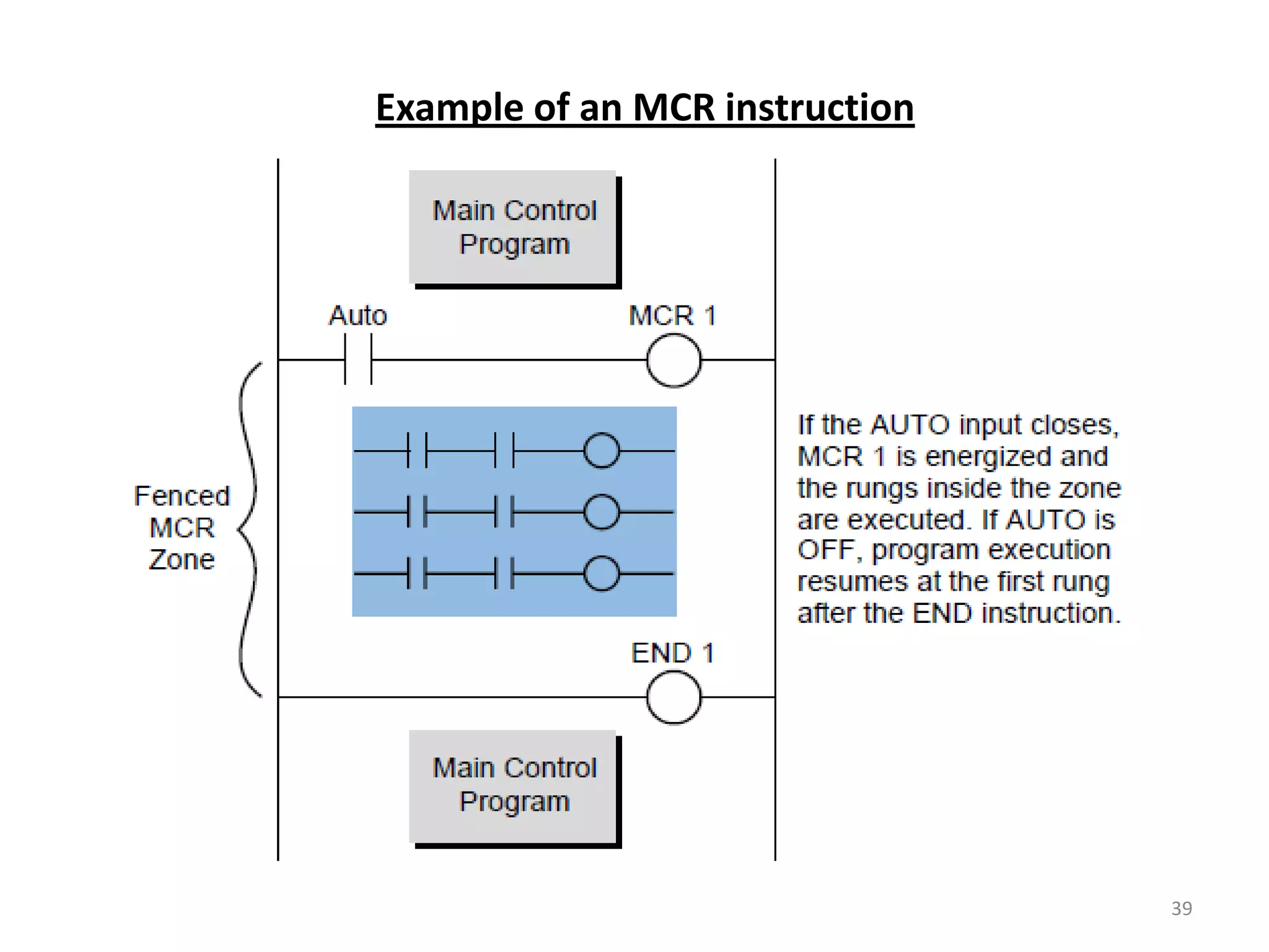
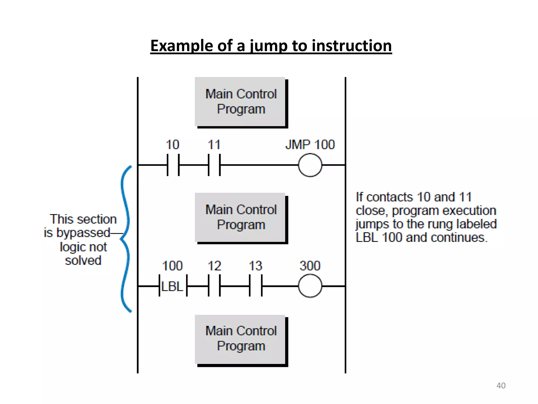
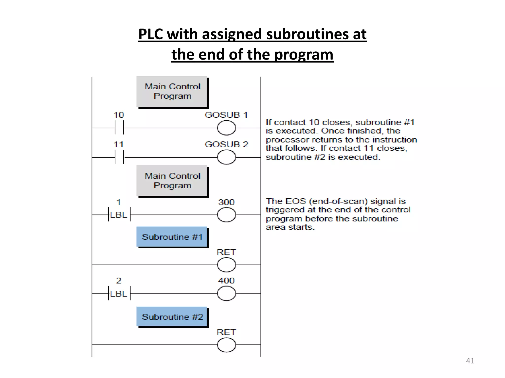
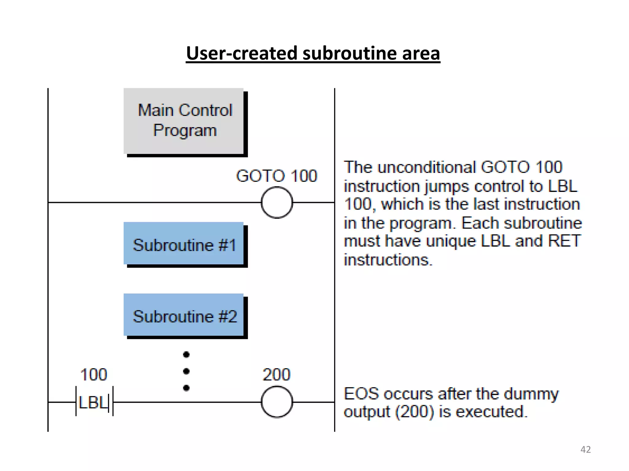
Function of program and flow control with branching instructions and the importance of subroutine areas.
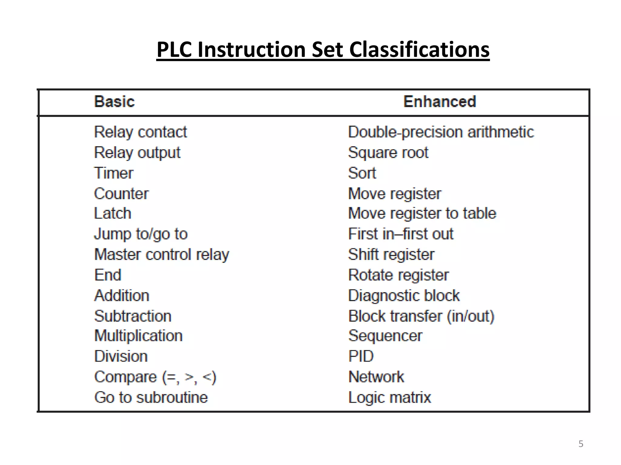
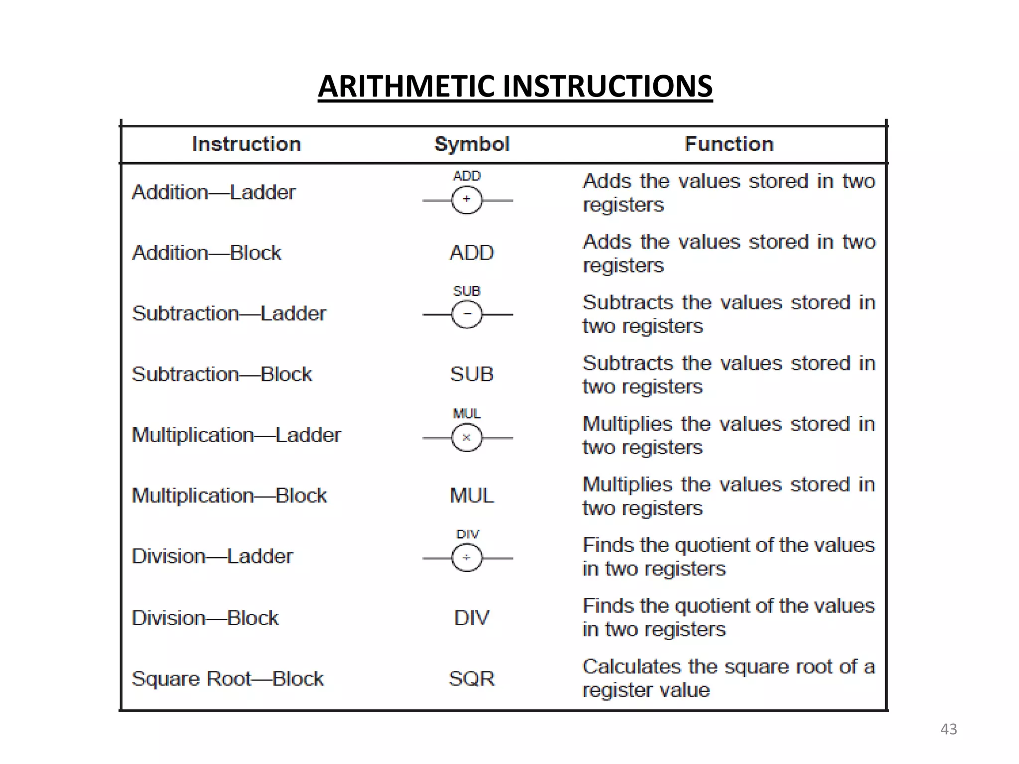
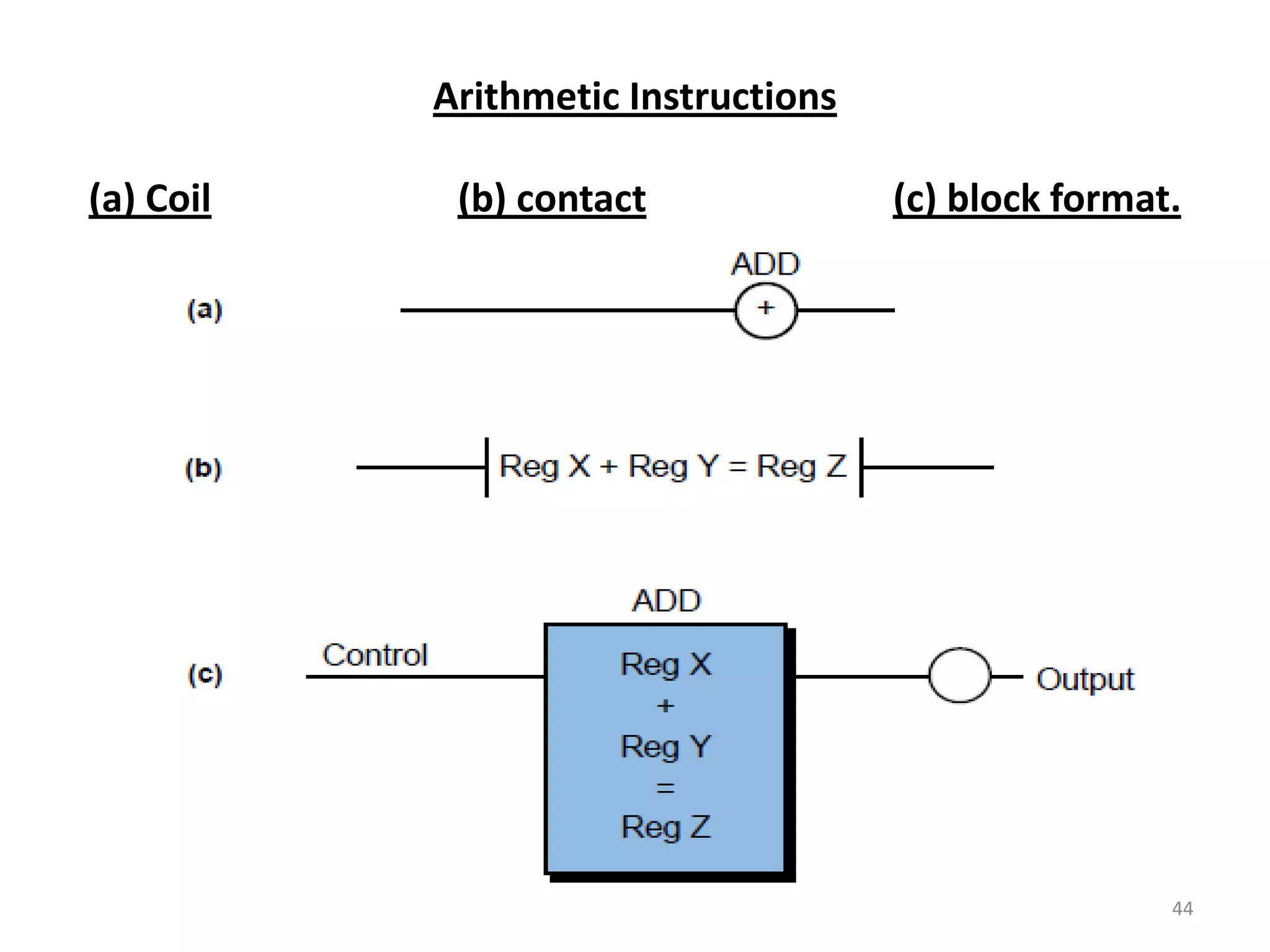
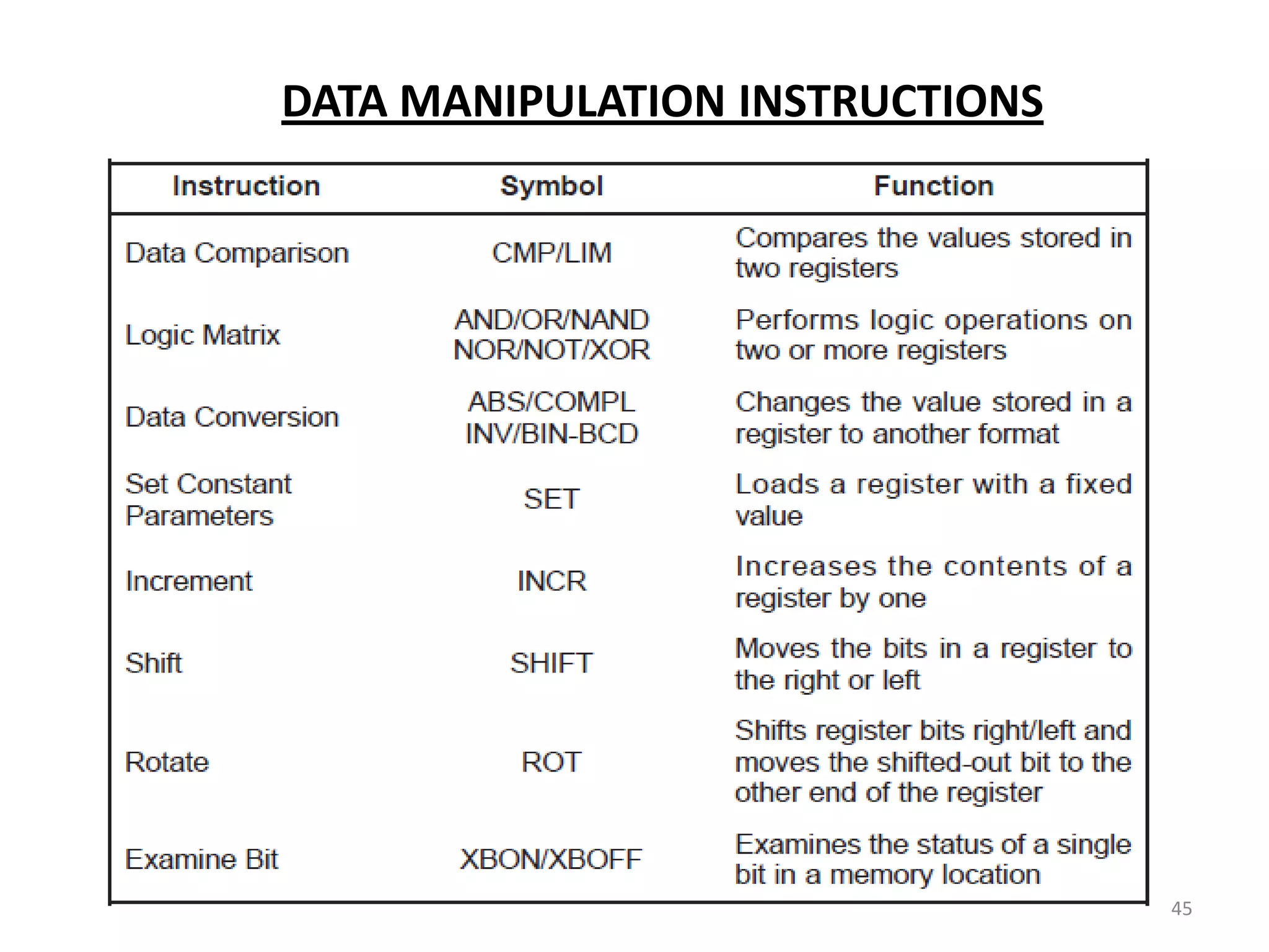
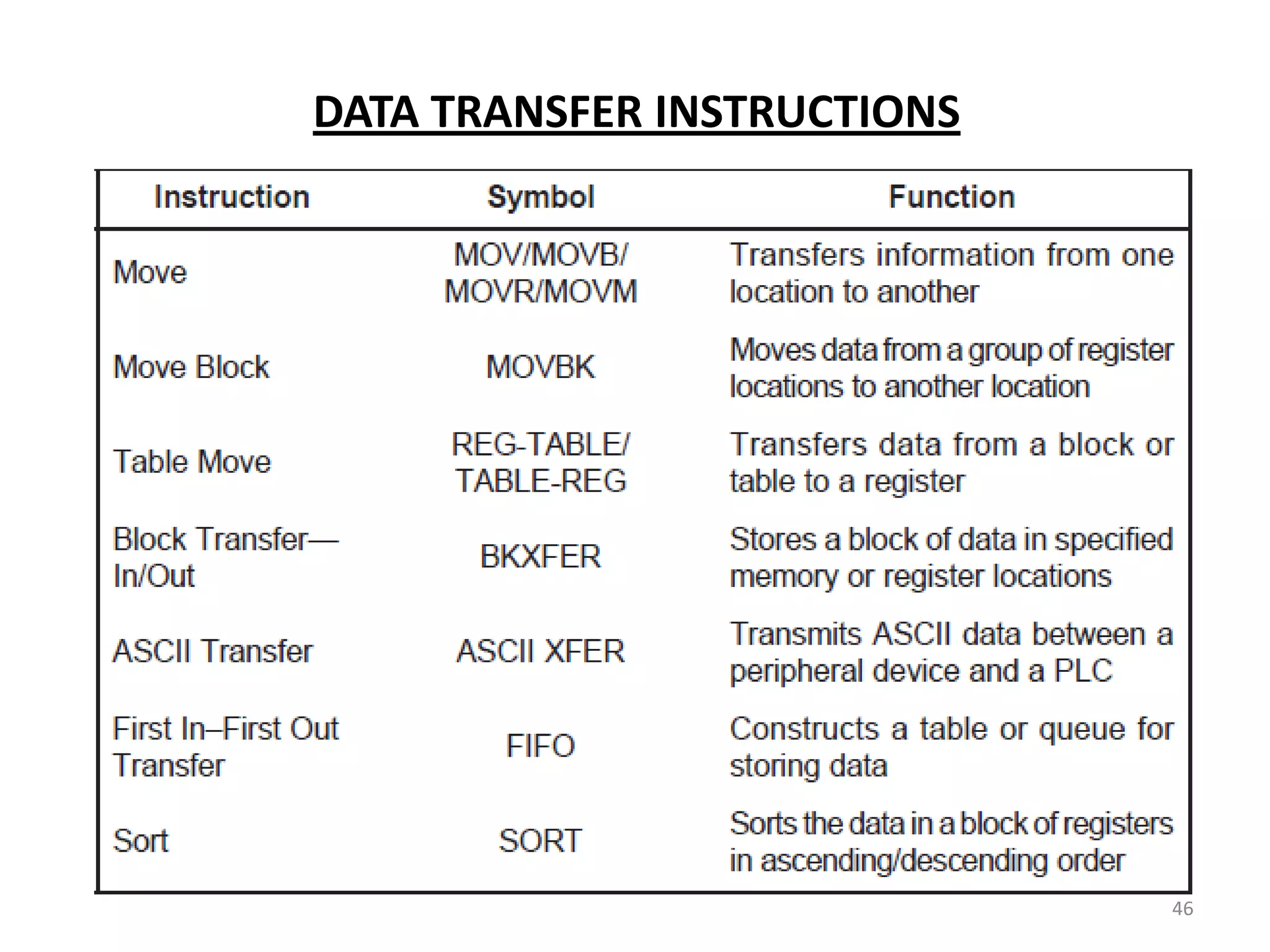
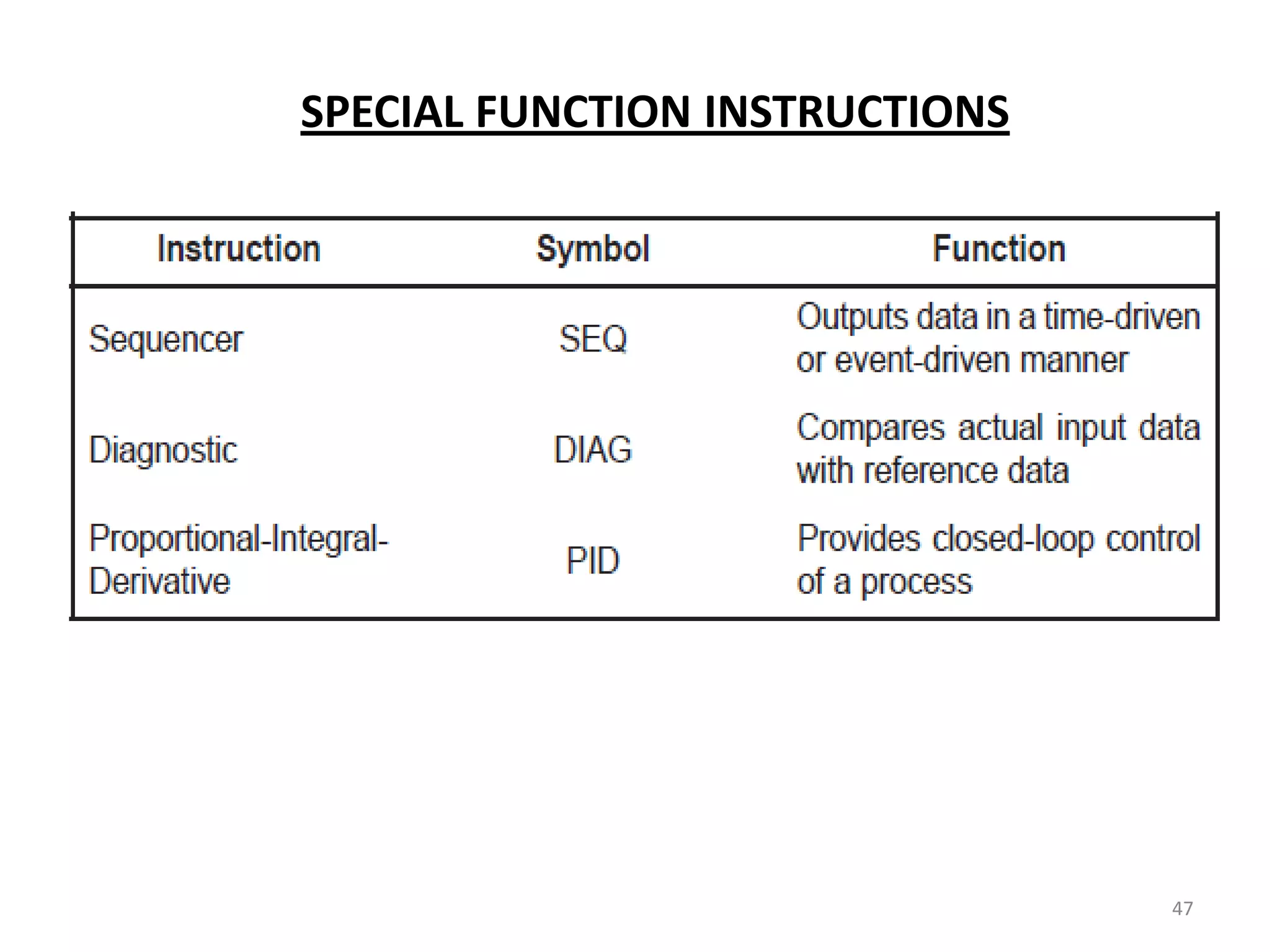
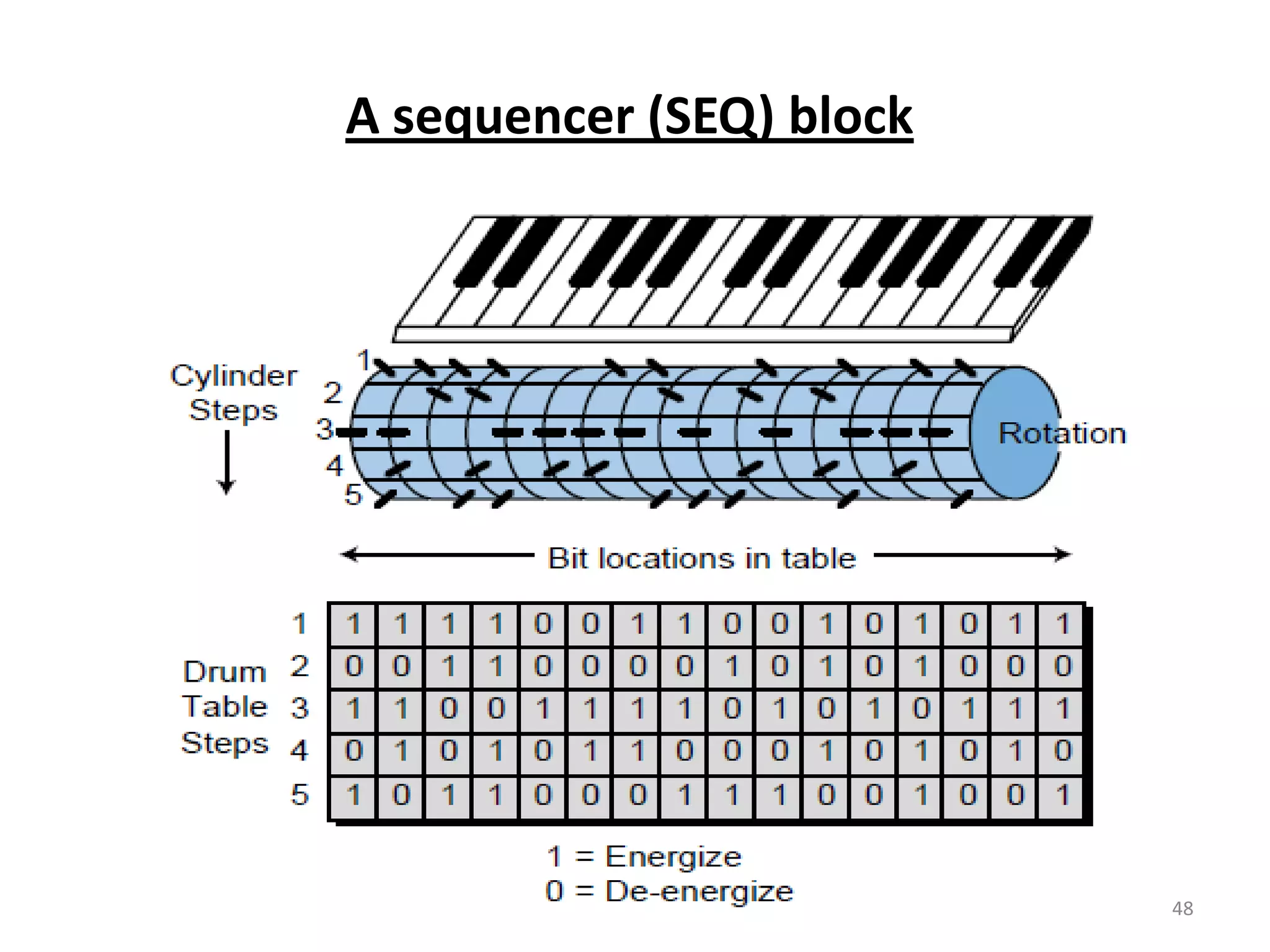
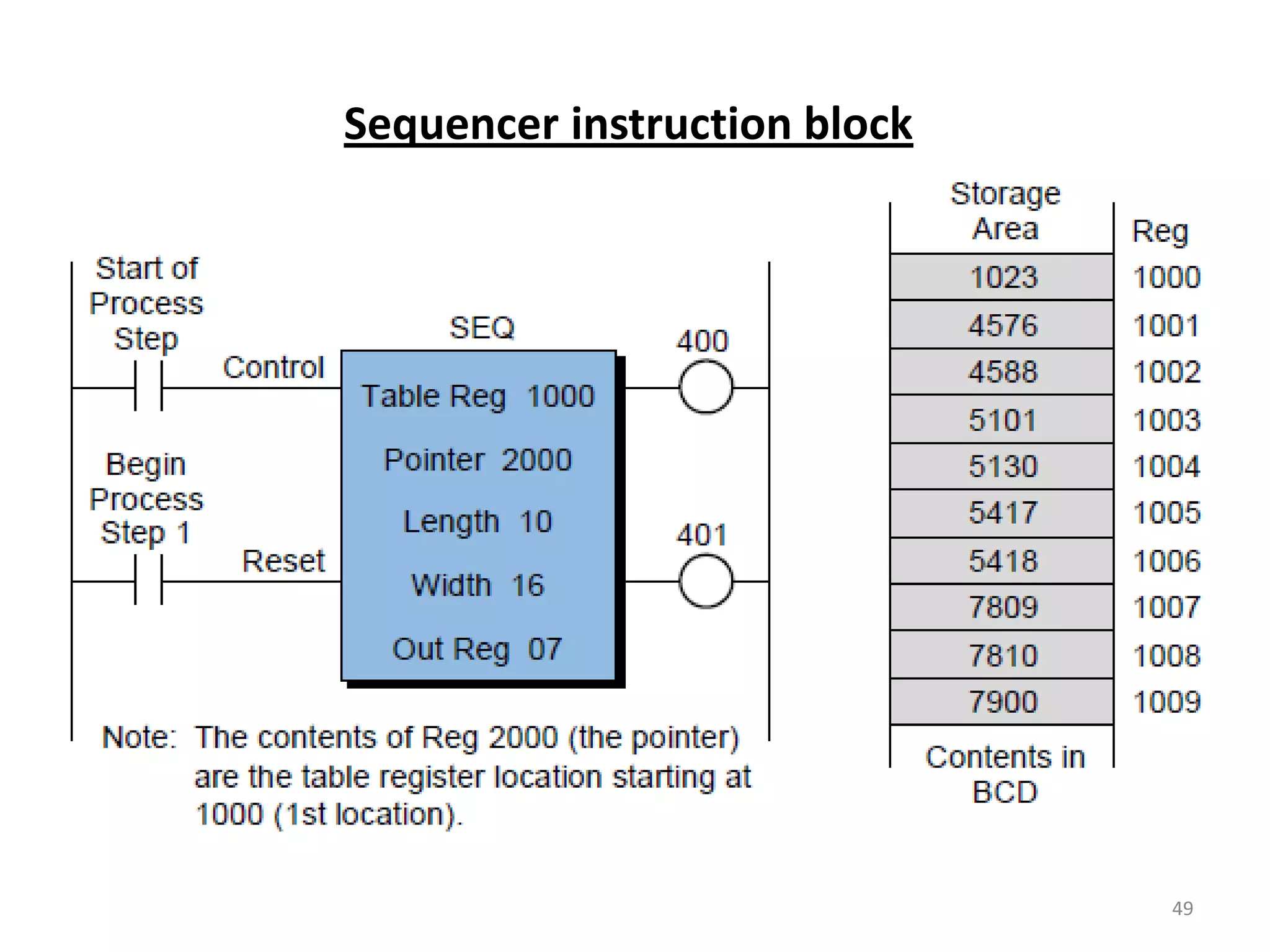
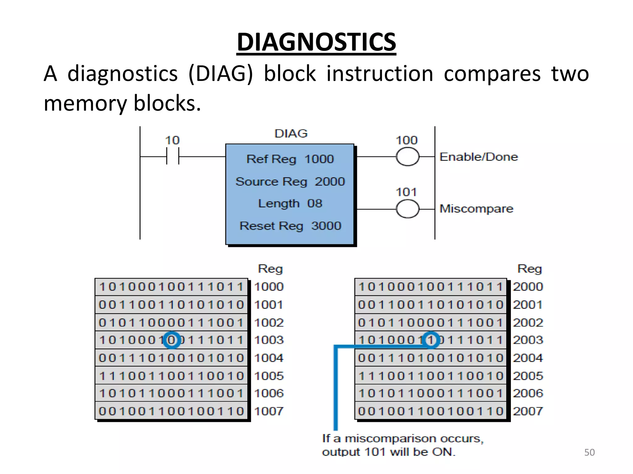
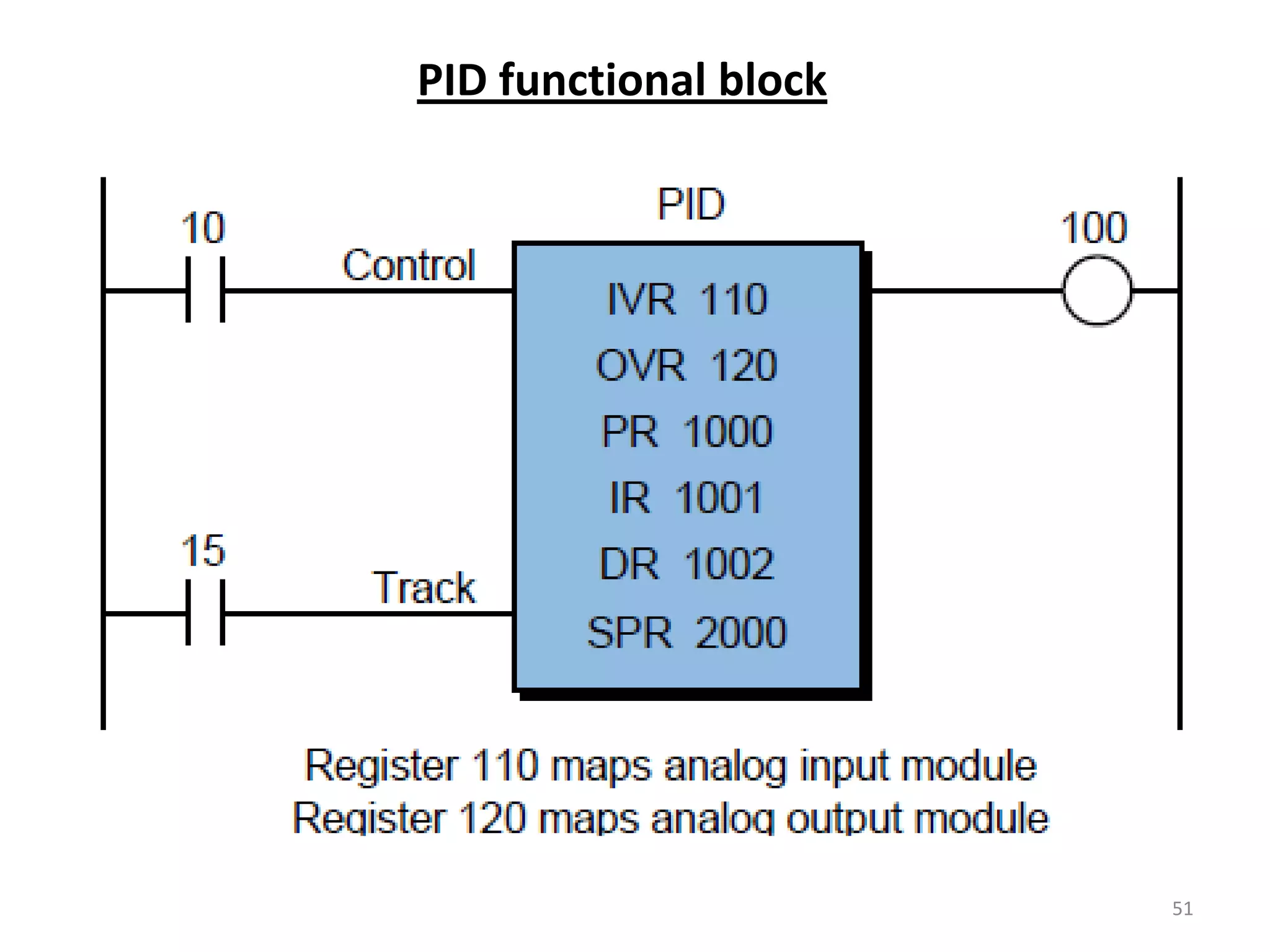
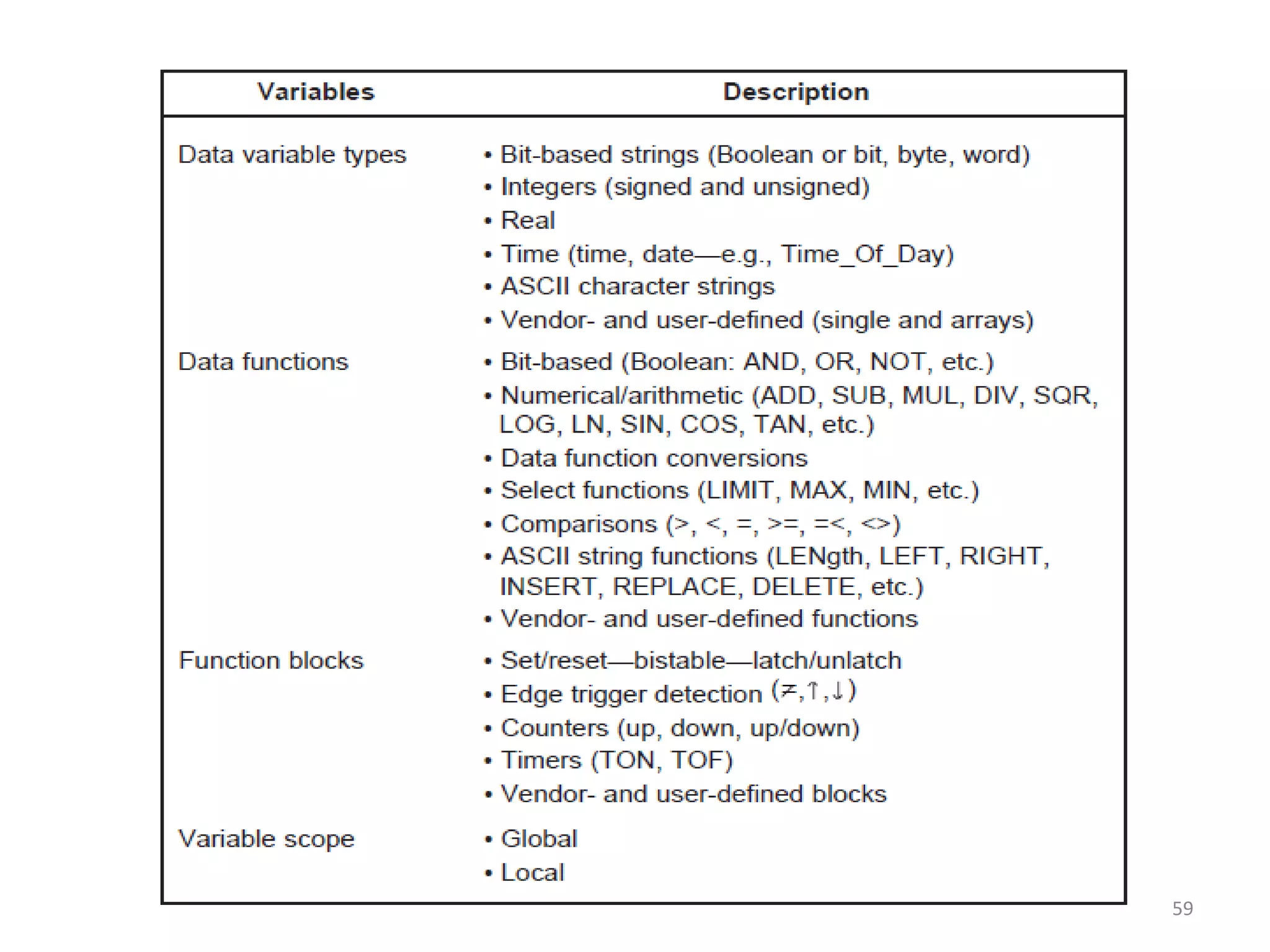
Focuses on arithmetic, data manipulation, transfer, and special function instructions within PLCs.
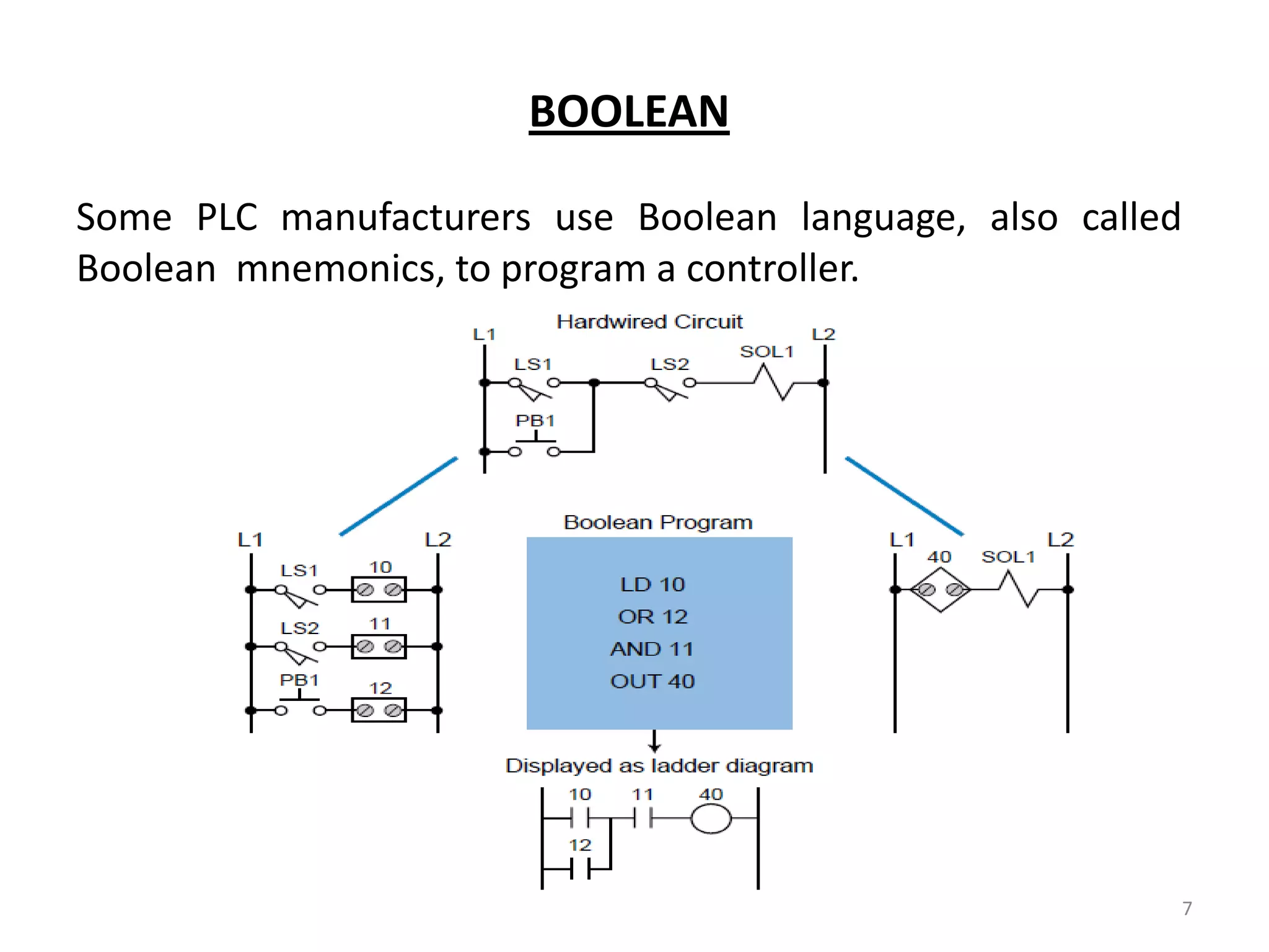
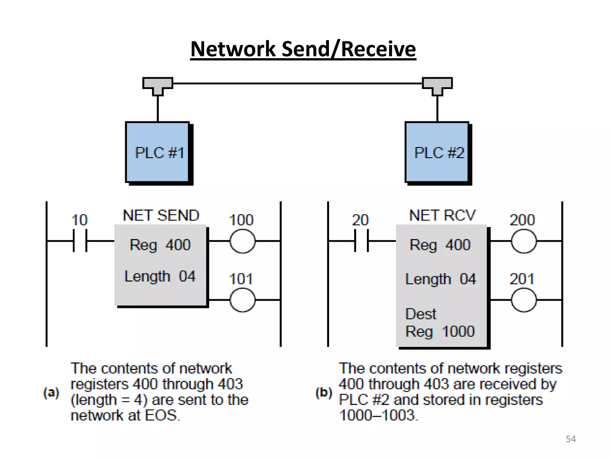
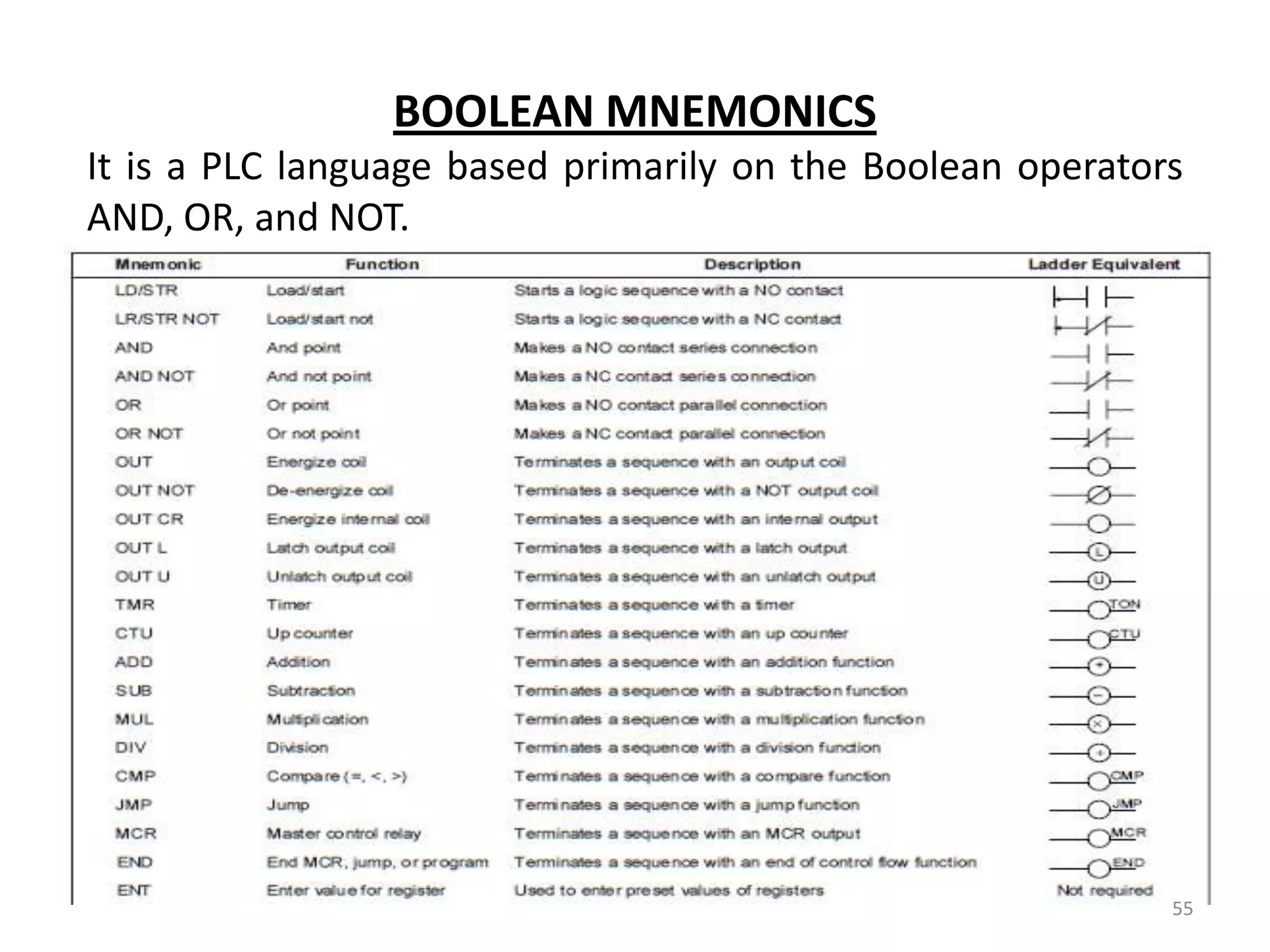
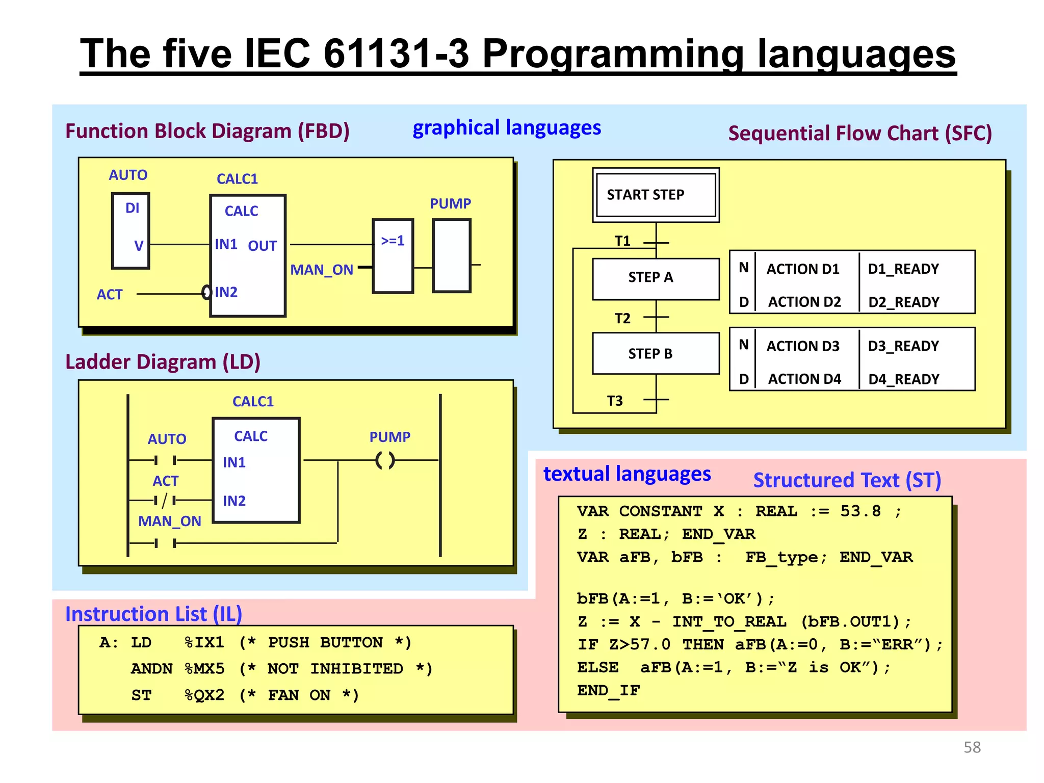
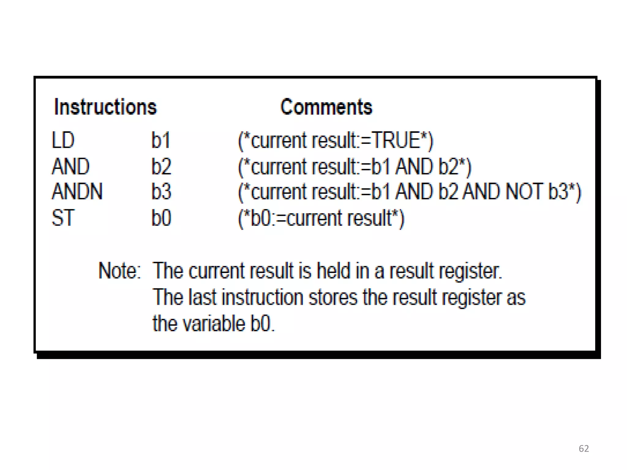
Explains Boolean mnemonics and the IEC 1131 standard, including graphical vs. text-based languages.
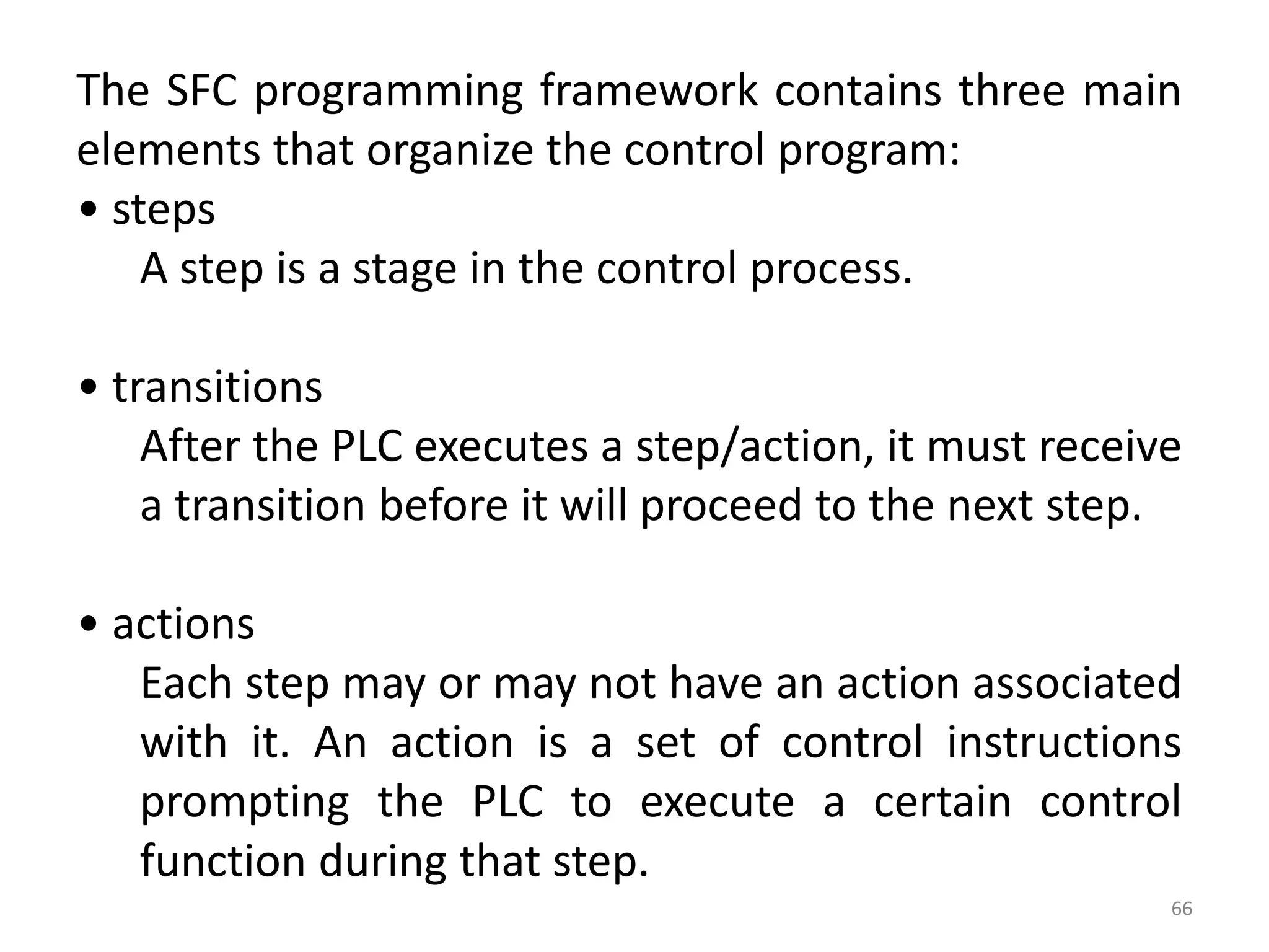
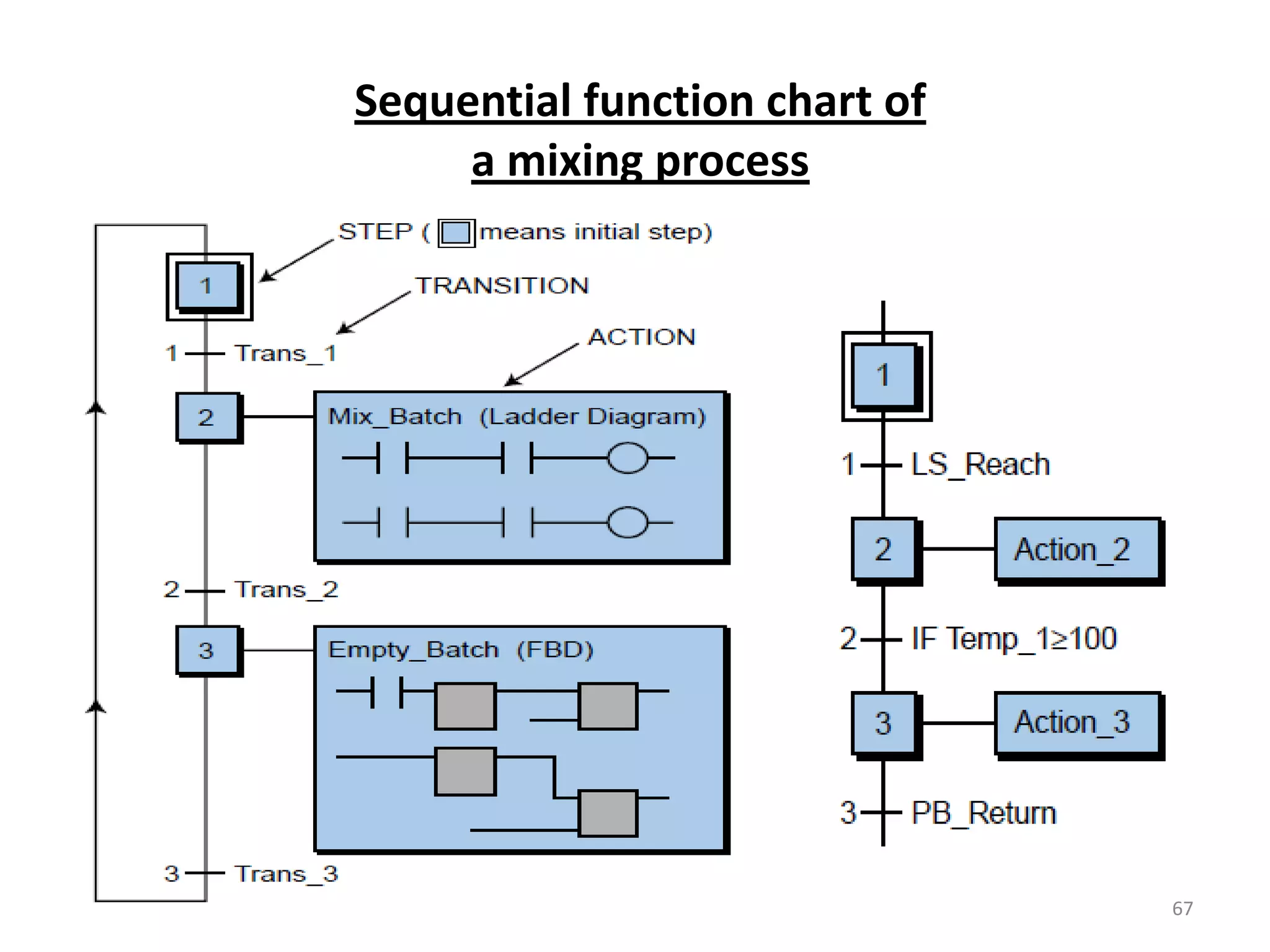
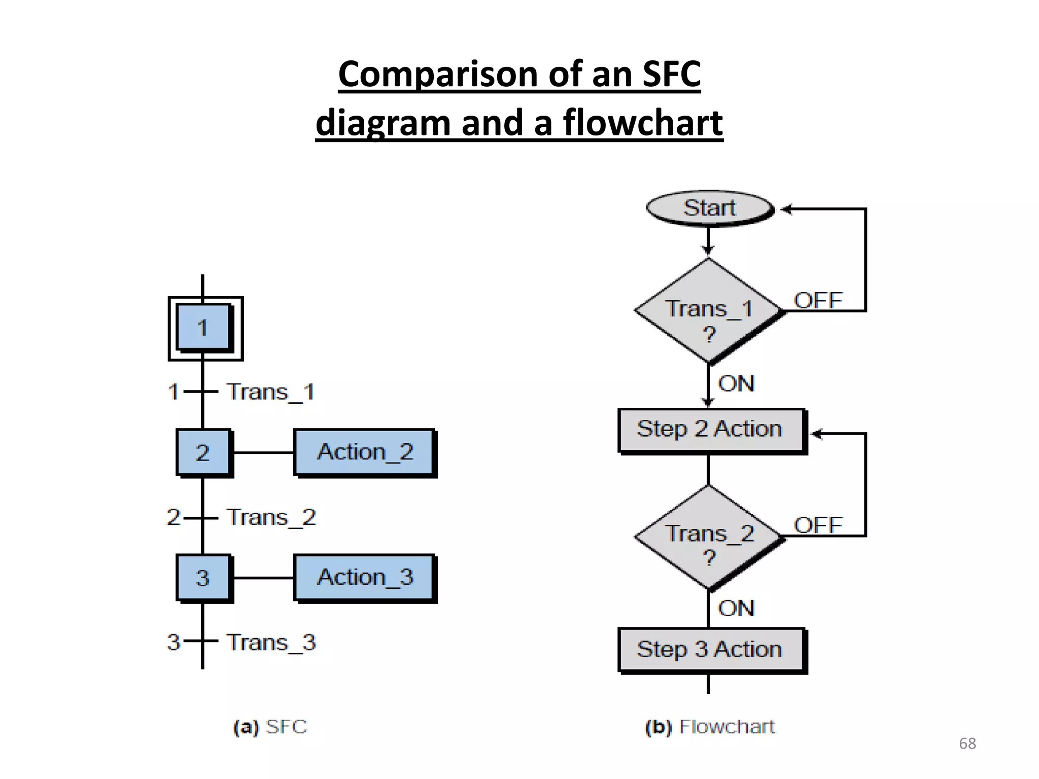
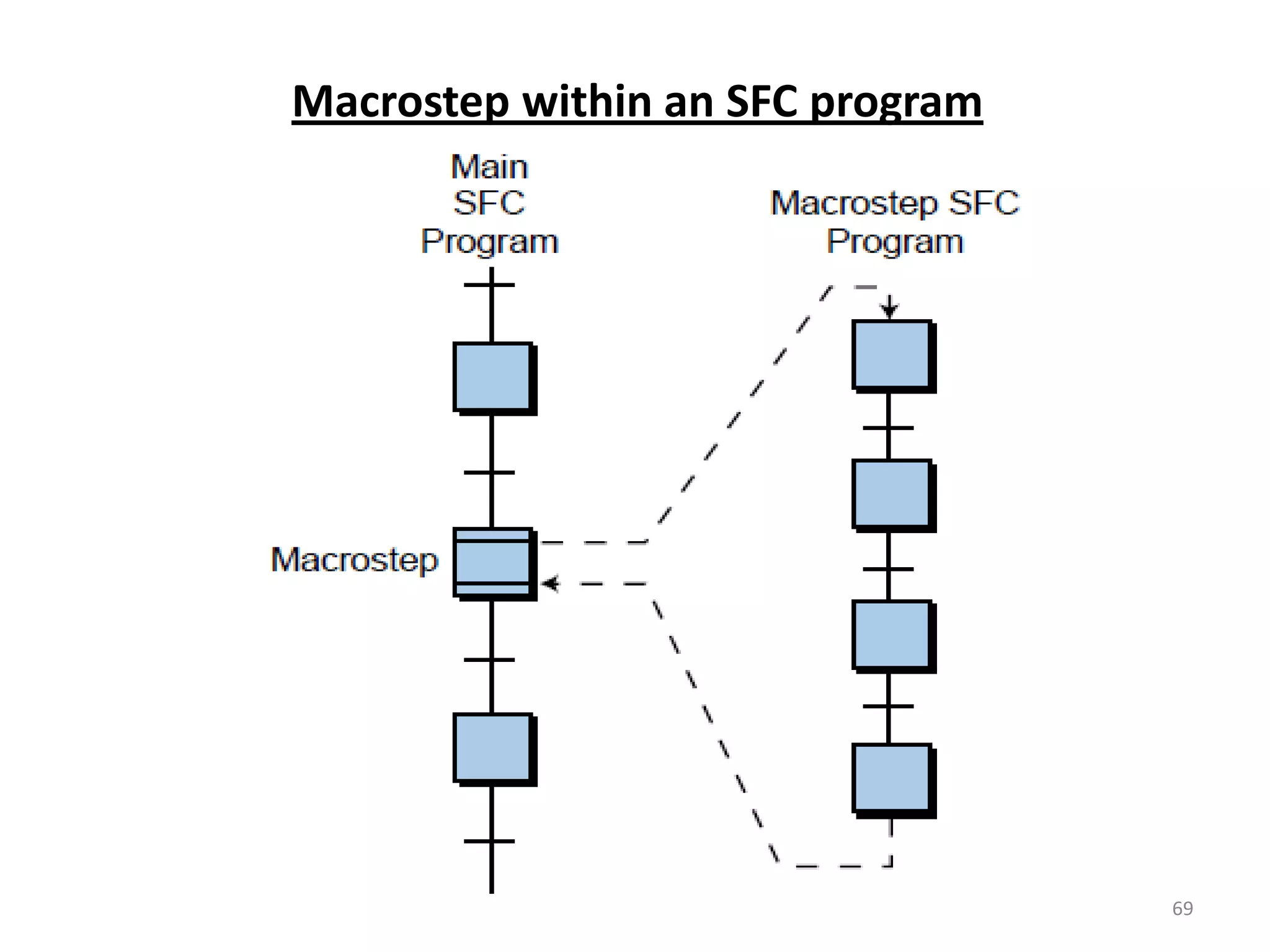
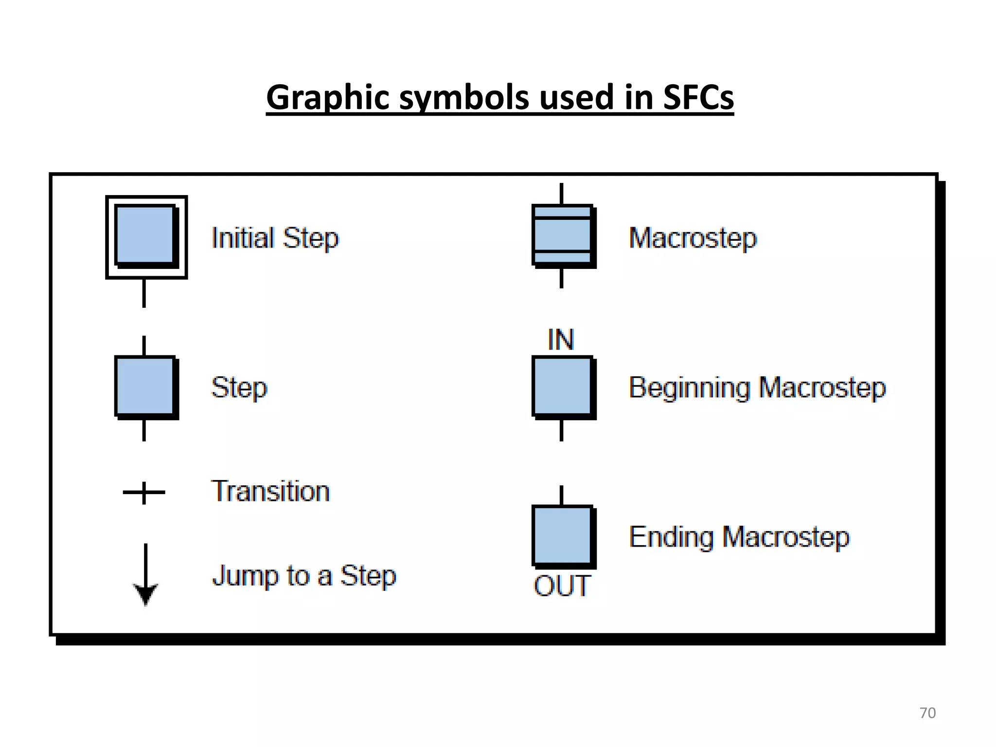
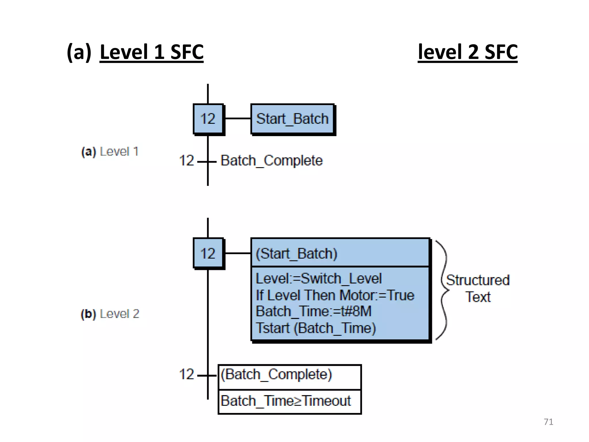
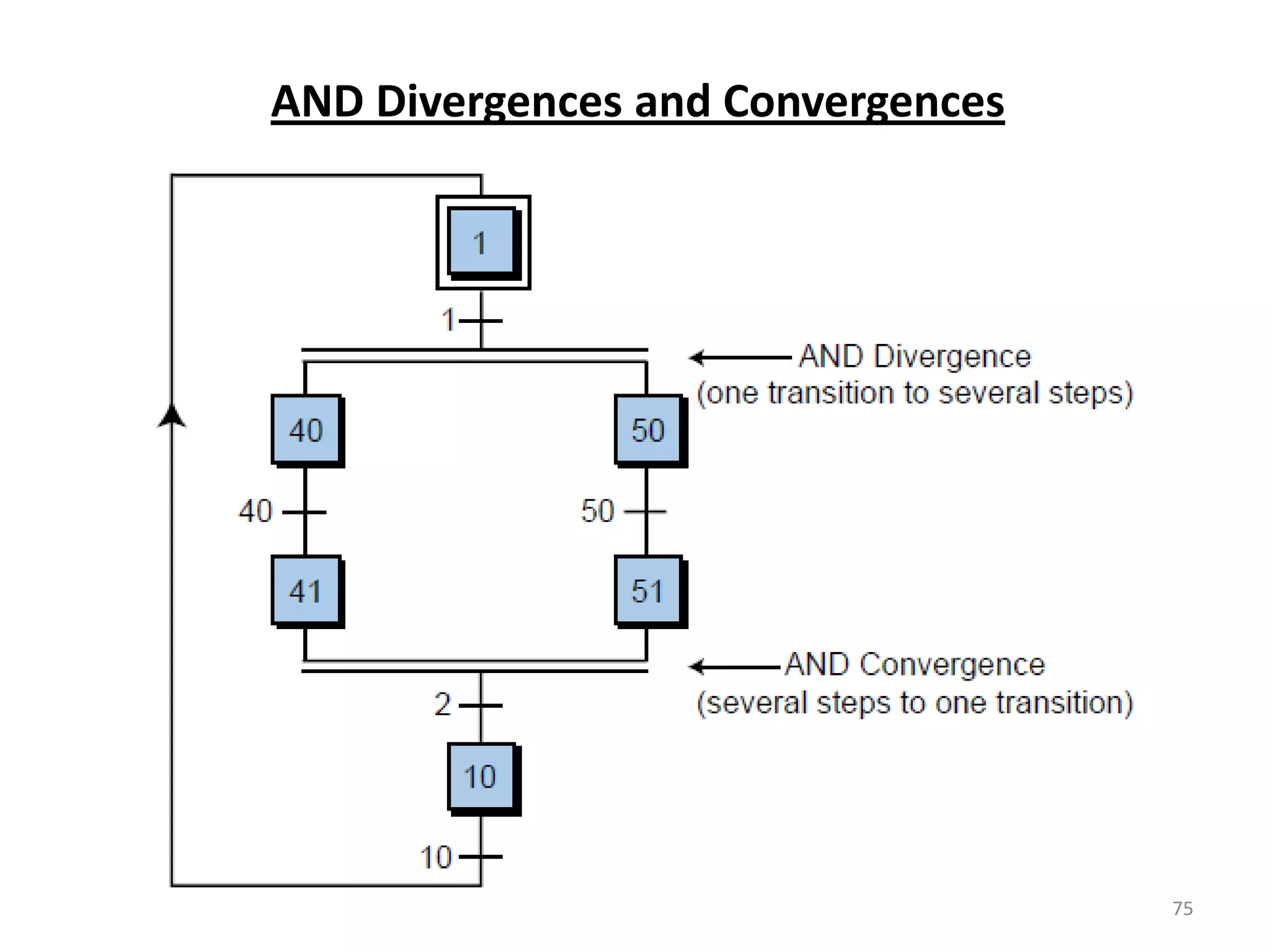
Introduces SFC as a graphical language for control sequences, including its main elements: steps and actions.
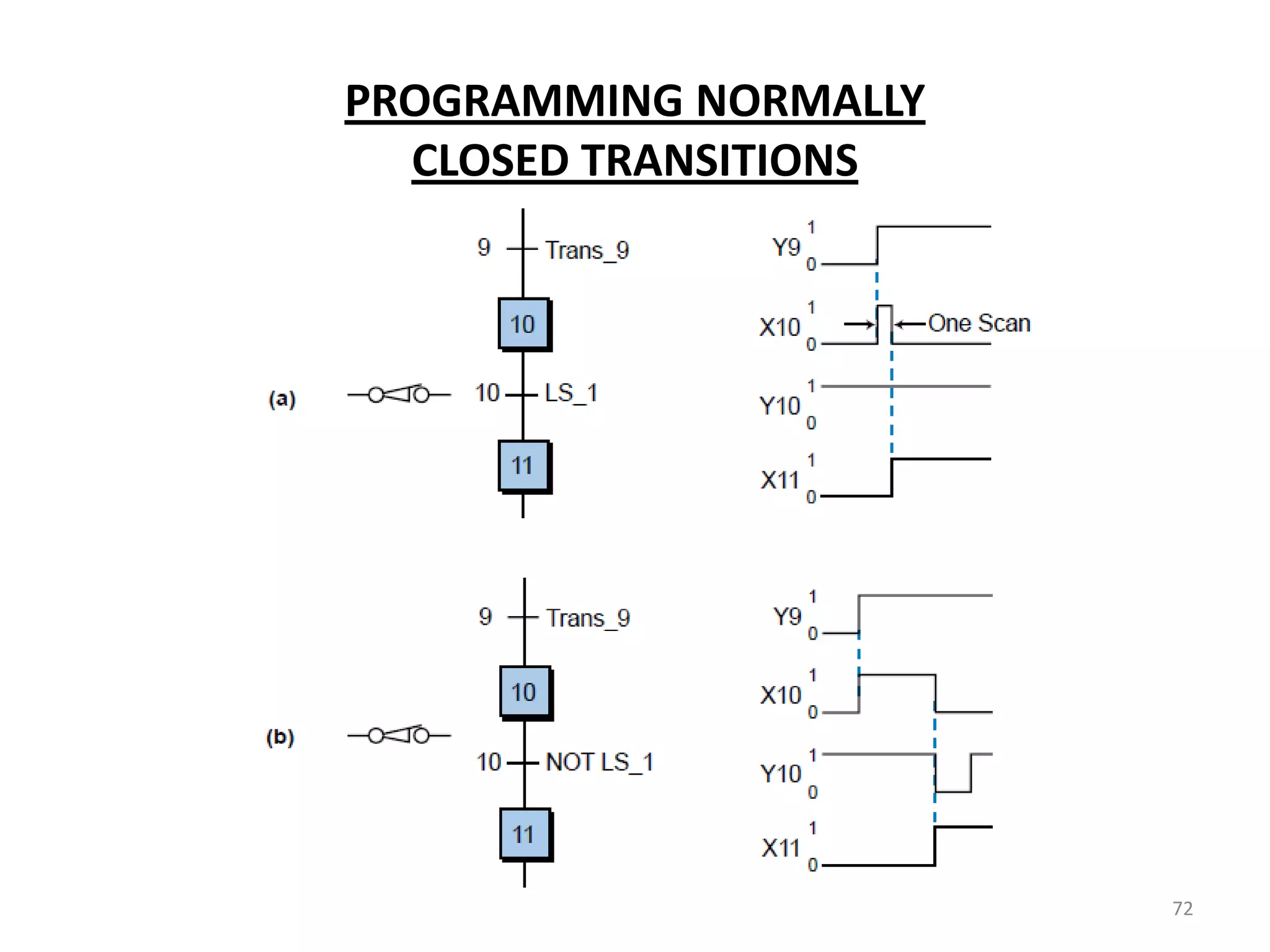
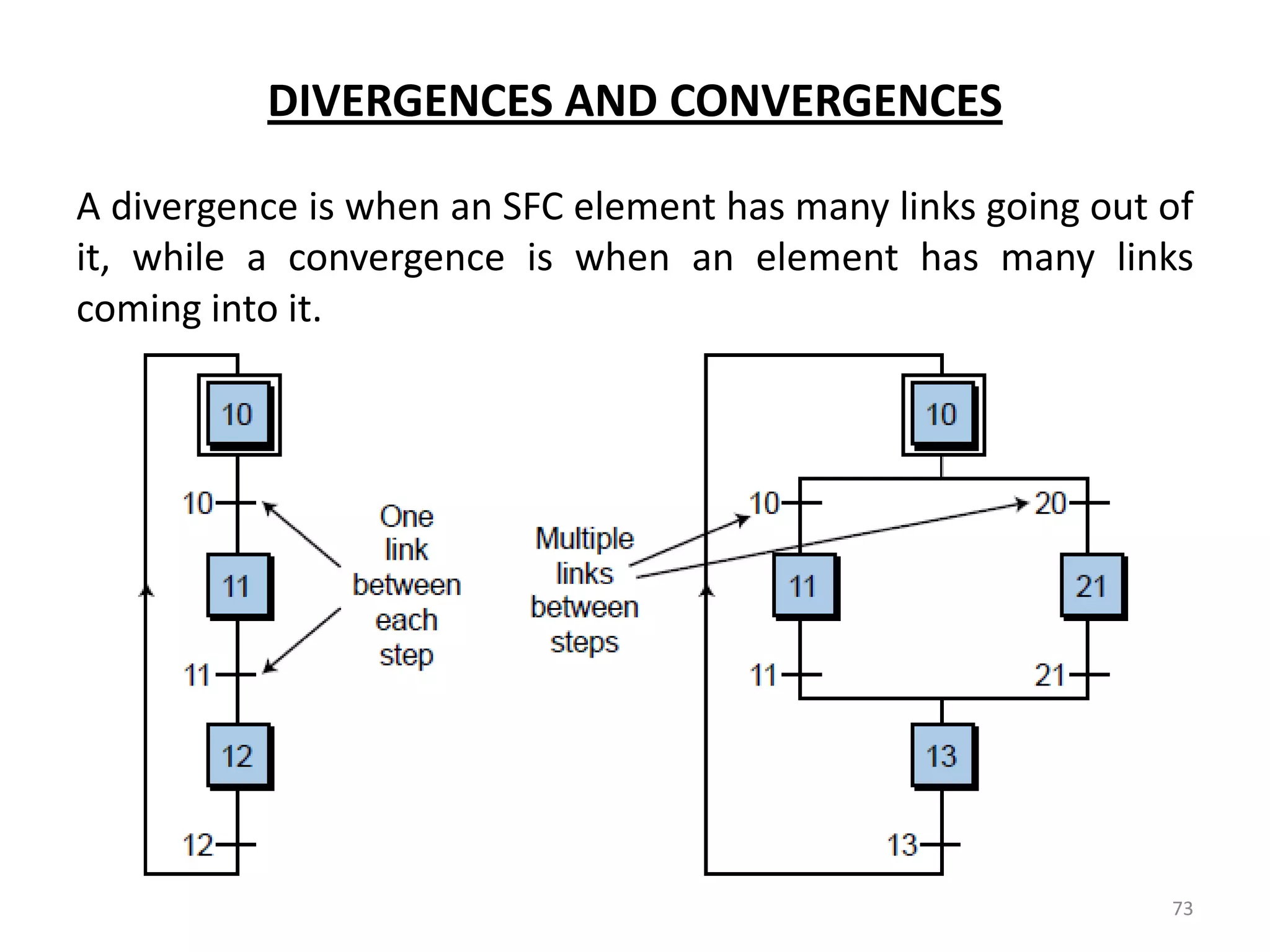
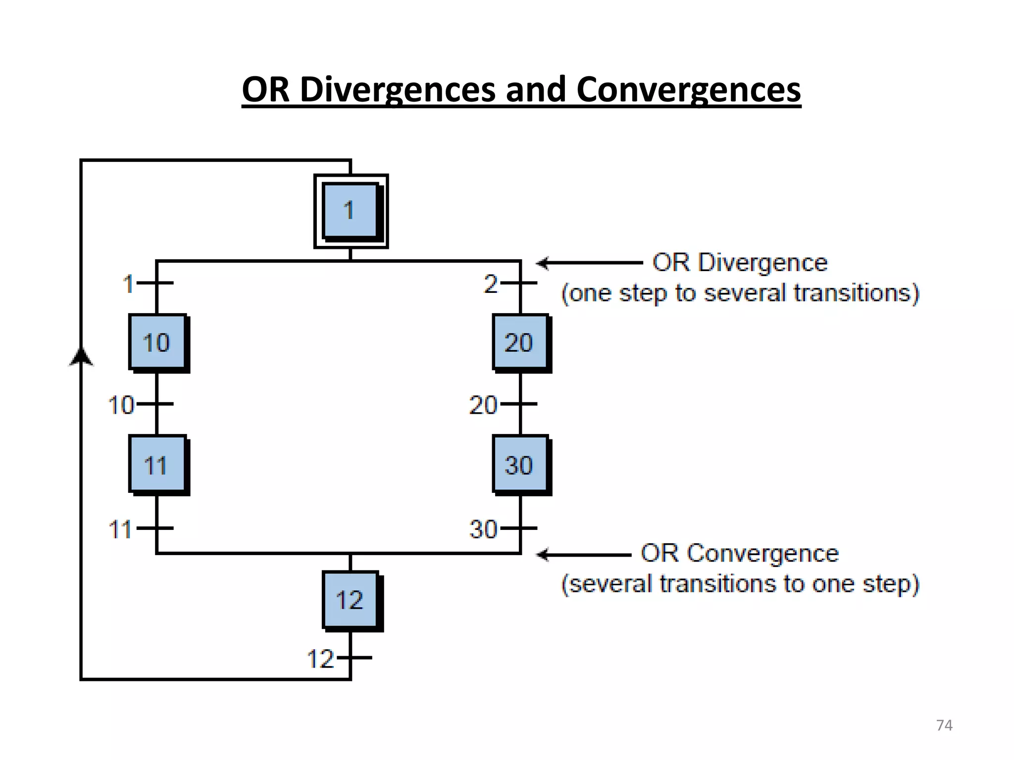
Details on SFC programming, including divergences, convergences and their representation in diagrams.
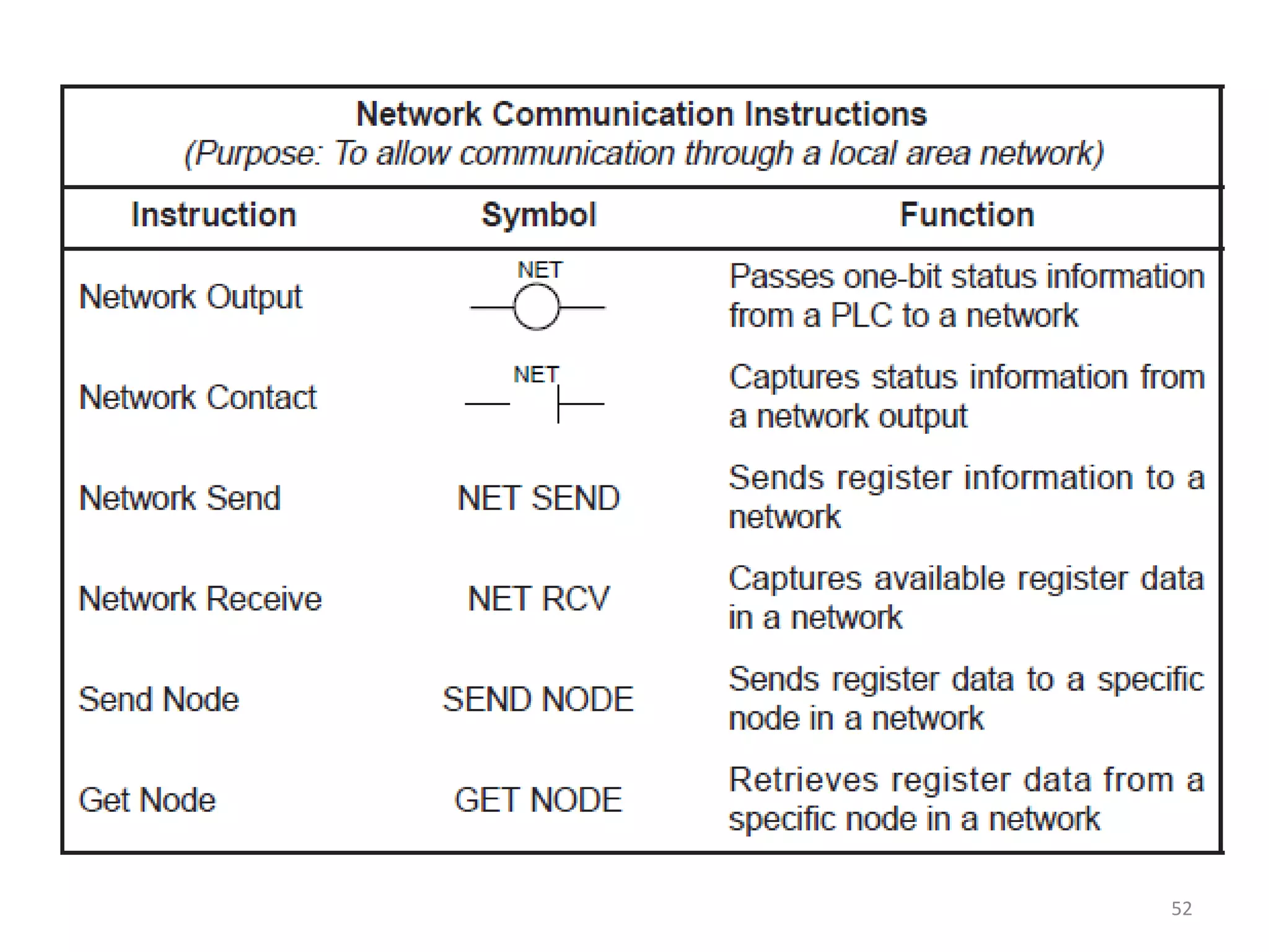
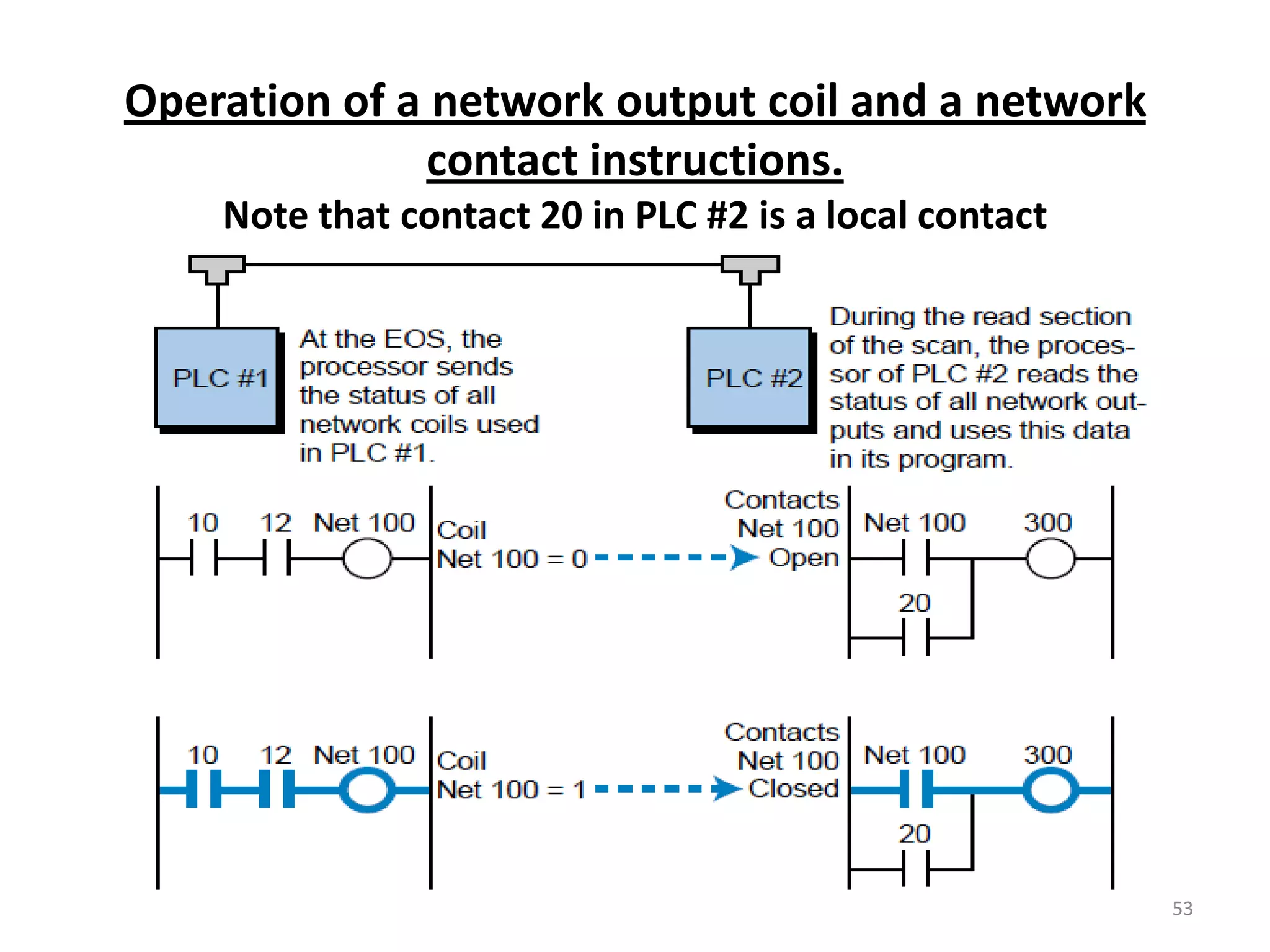
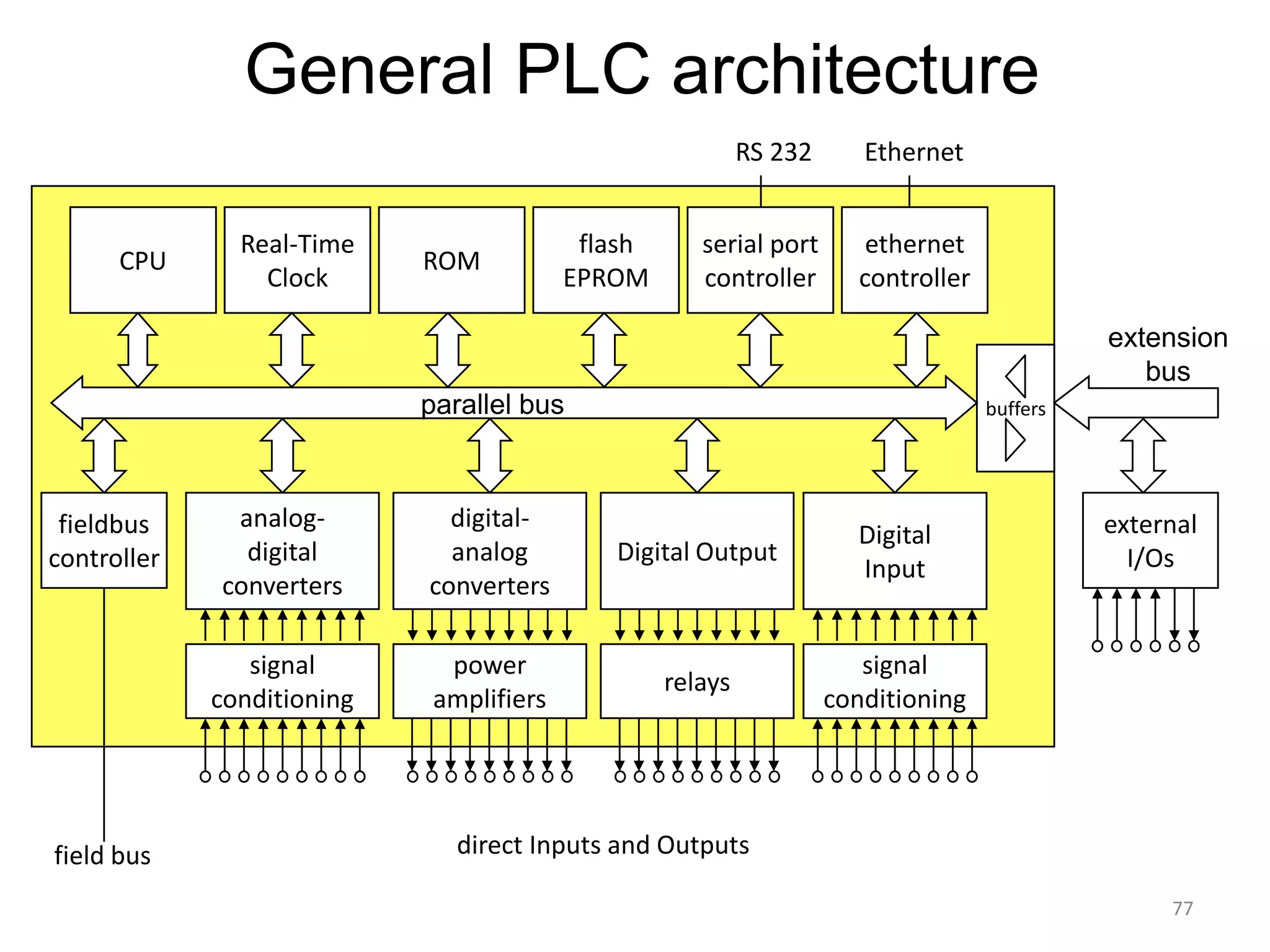
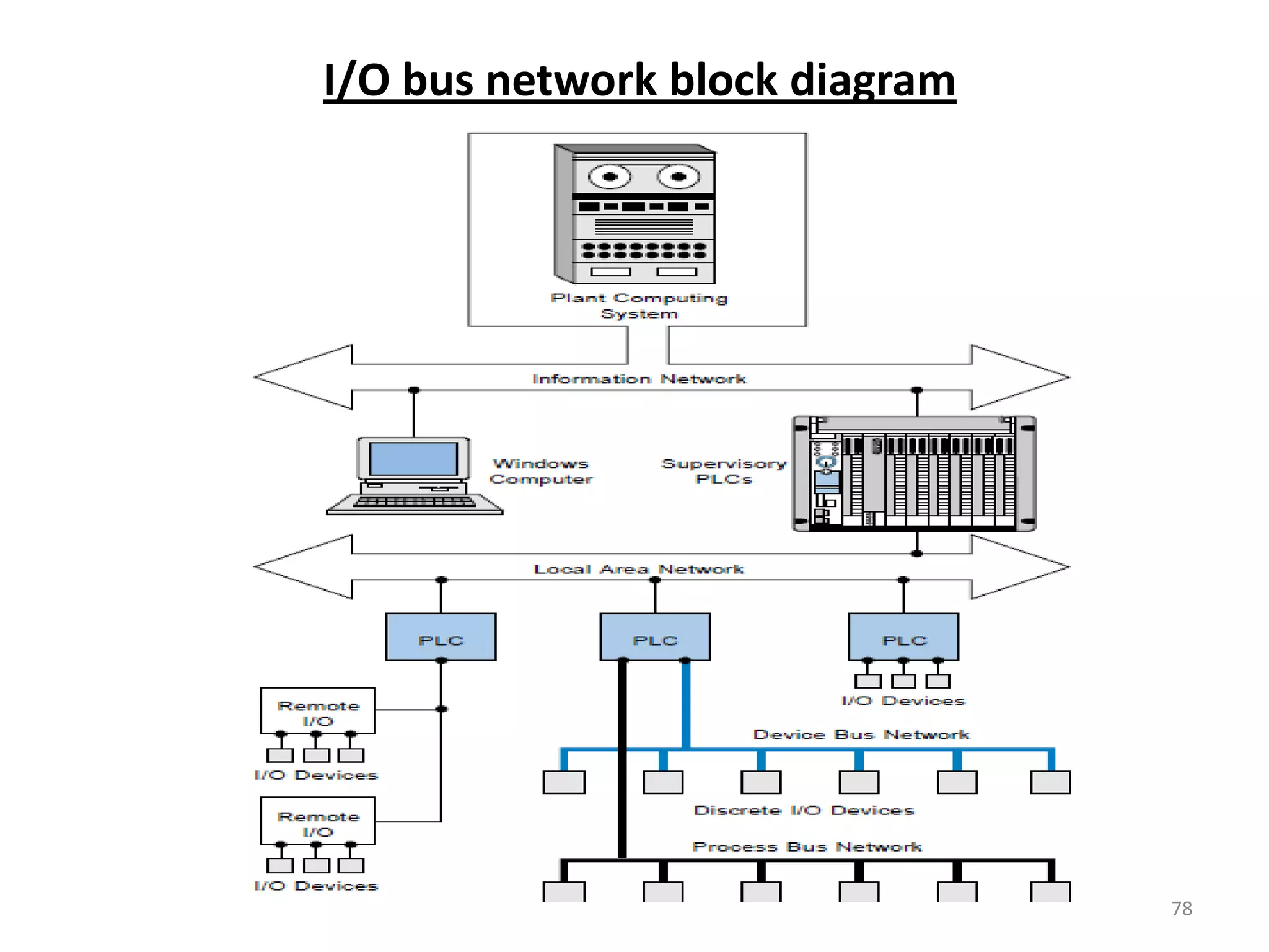
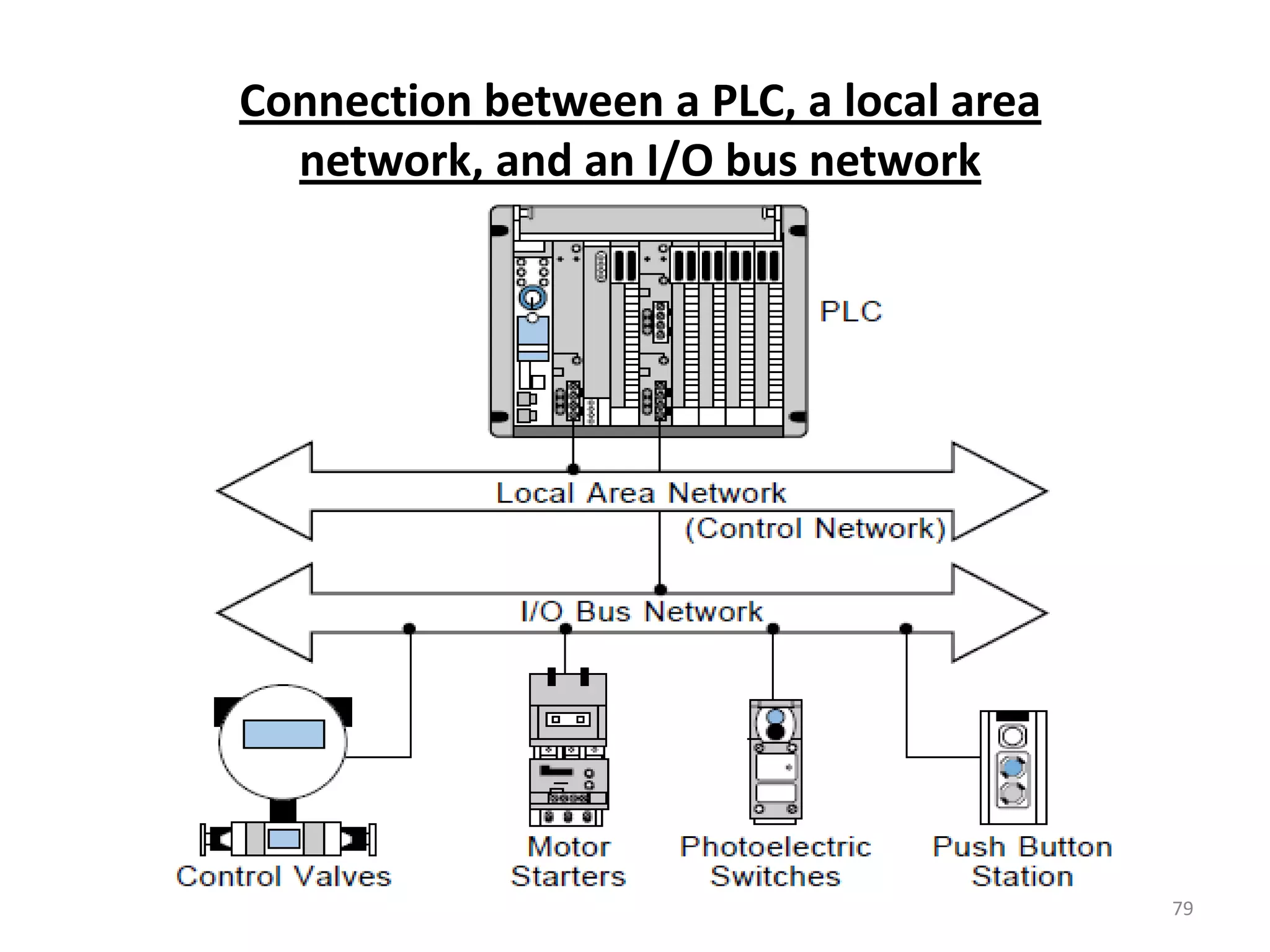
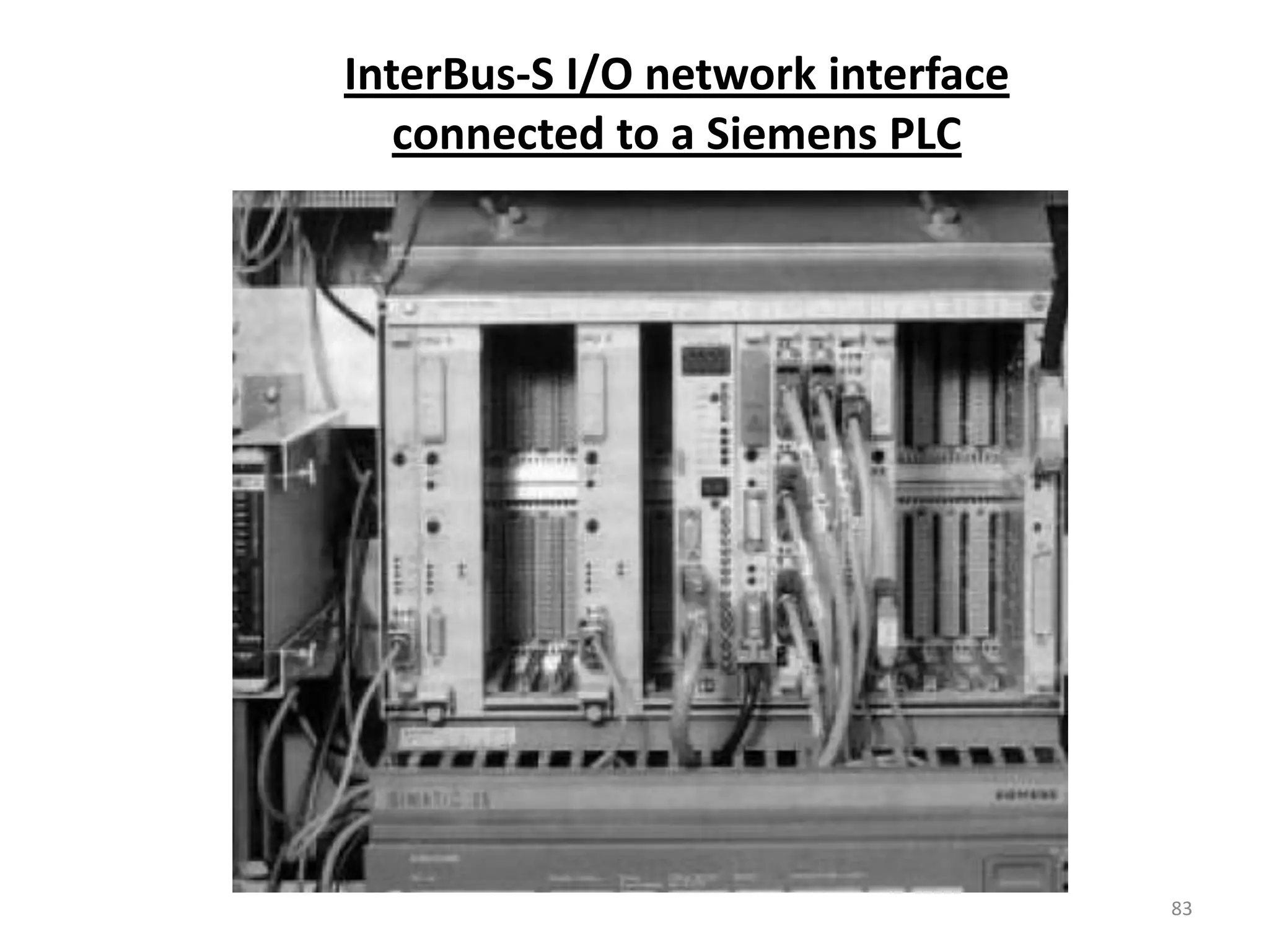
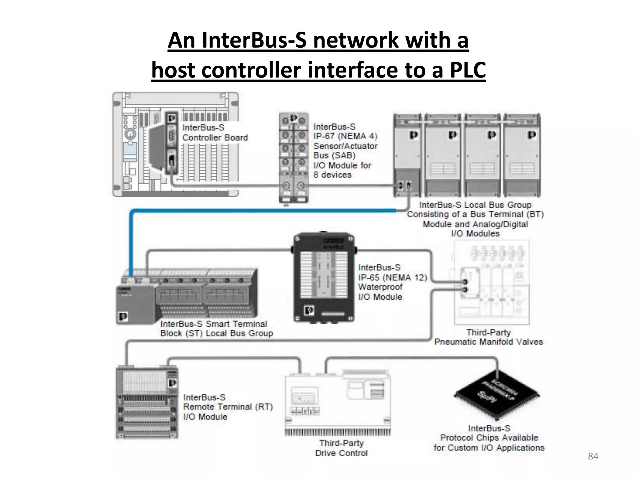
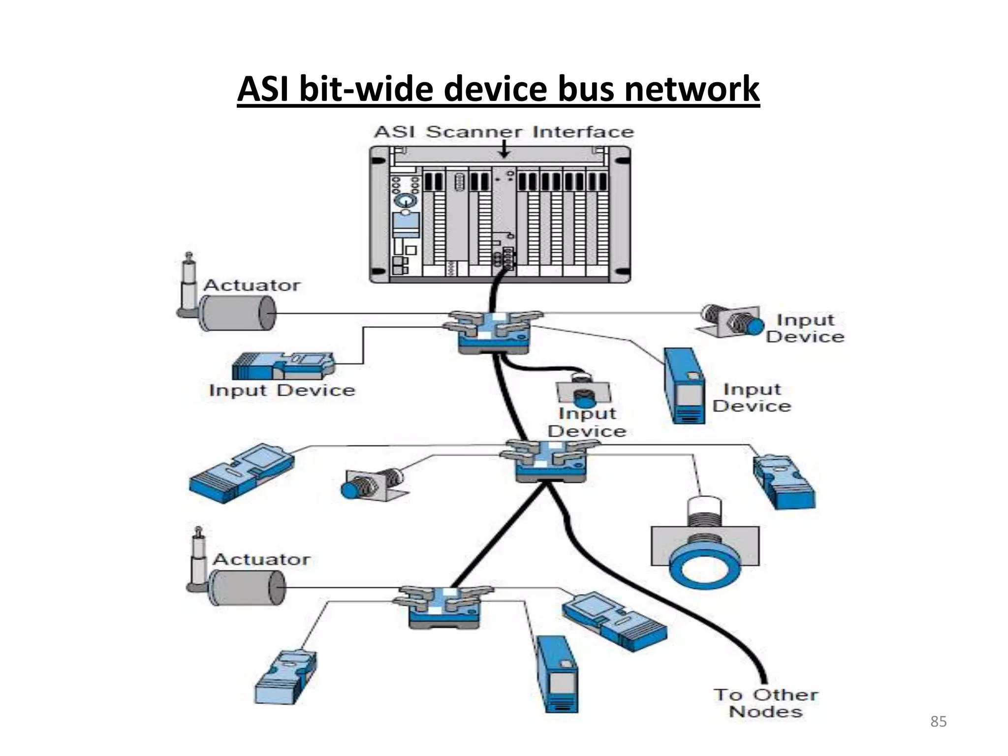
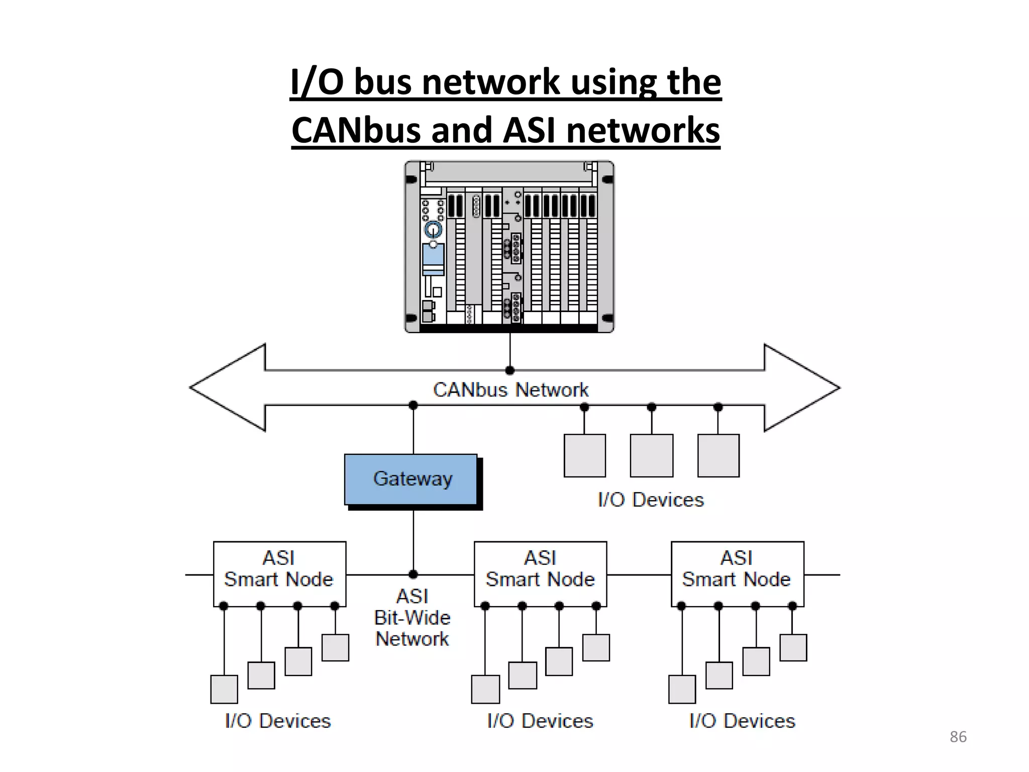
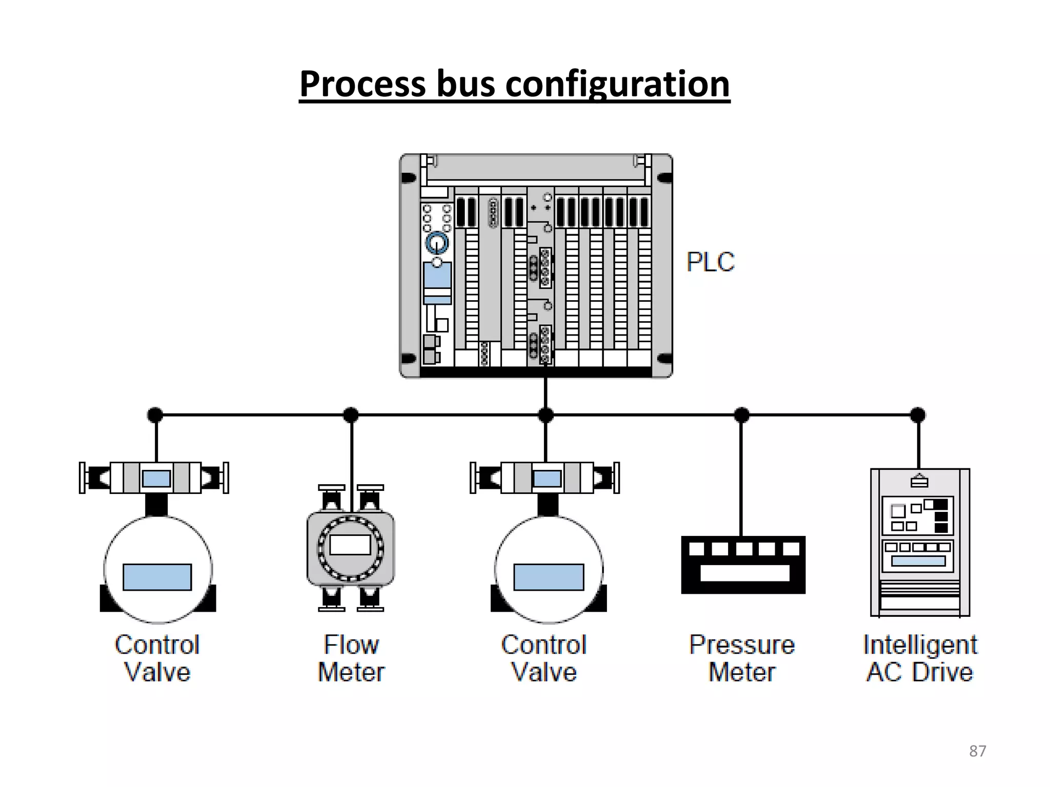
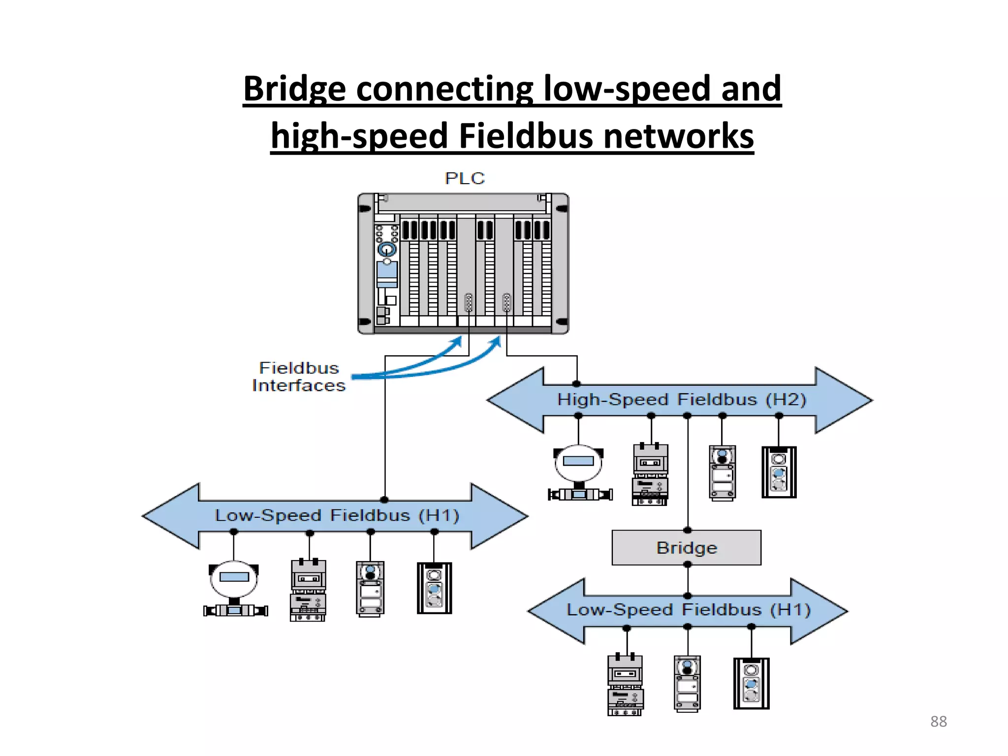
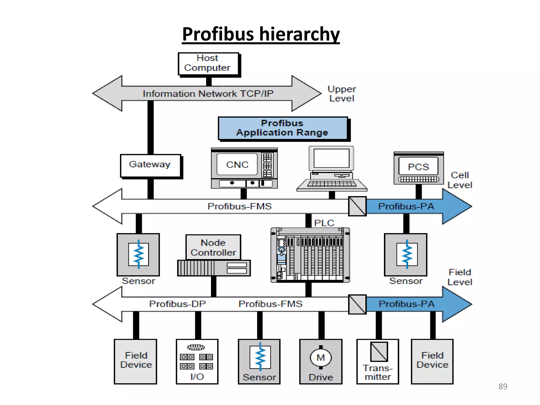
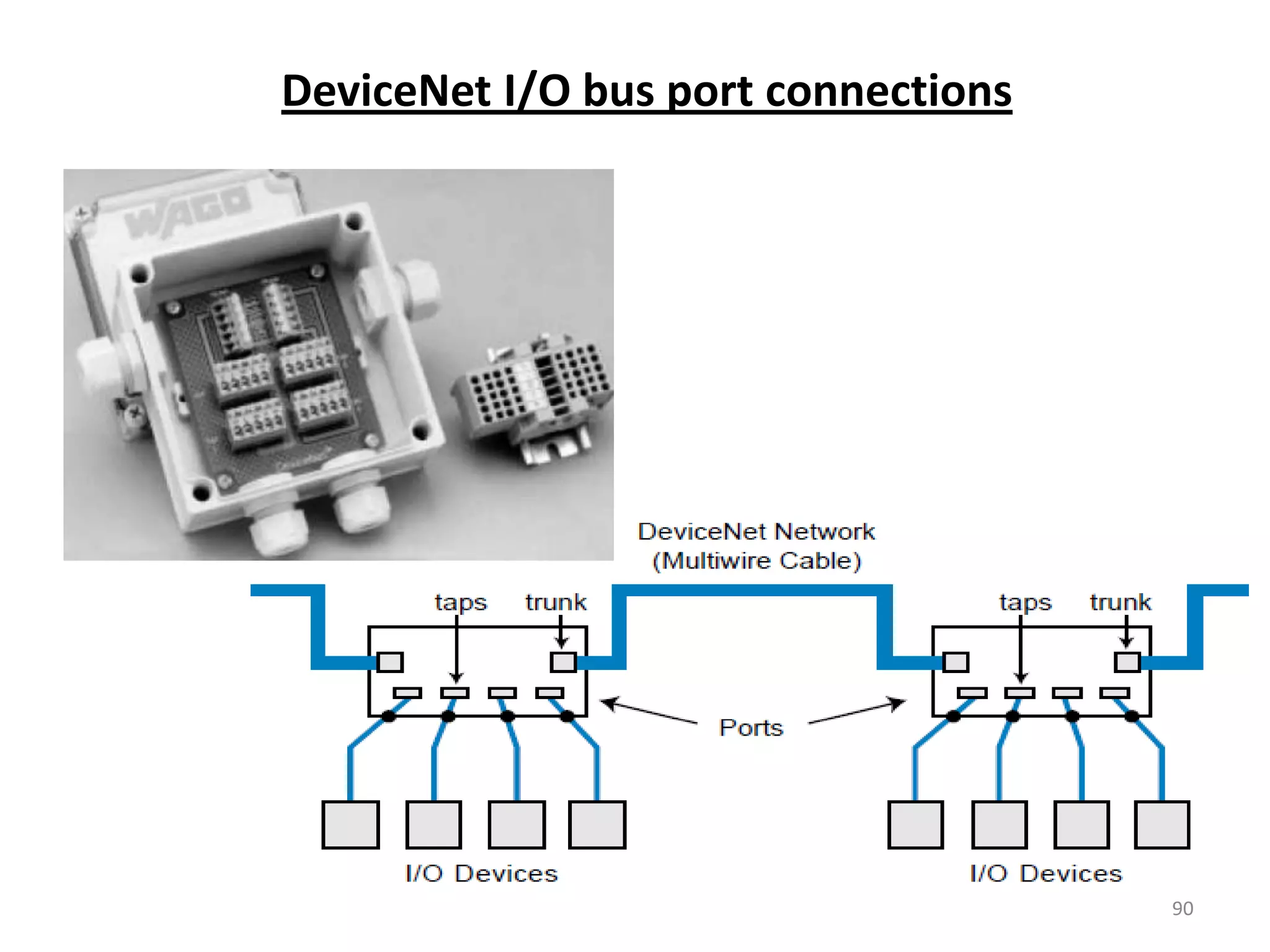
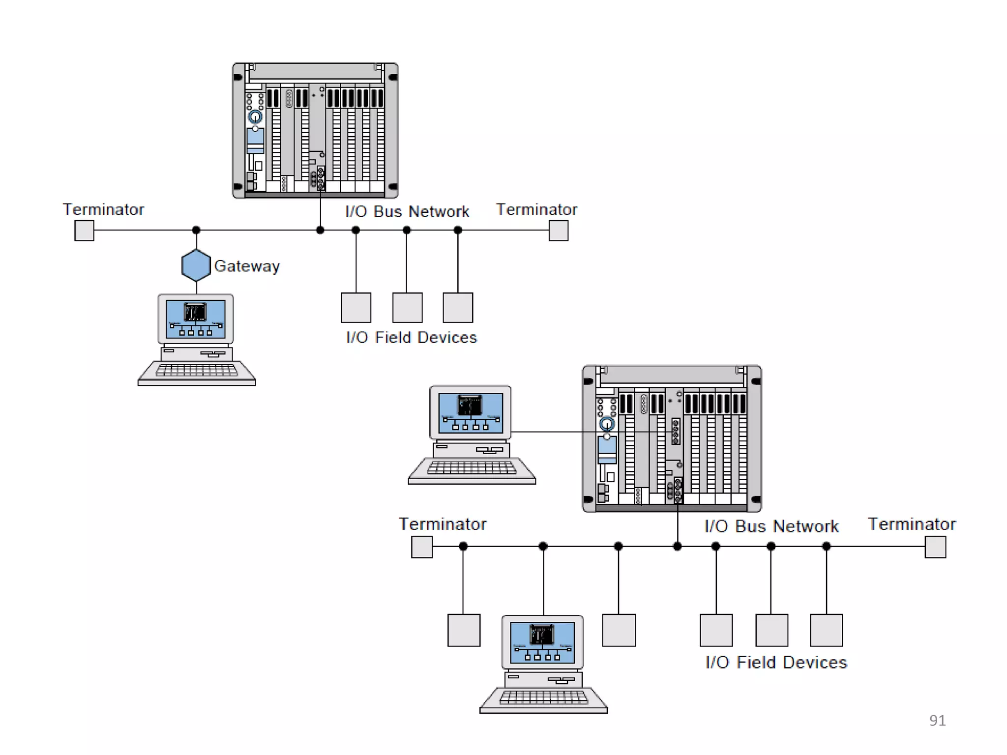
General architecture of PLCs, focusing on real-time components and I/O bus networks.
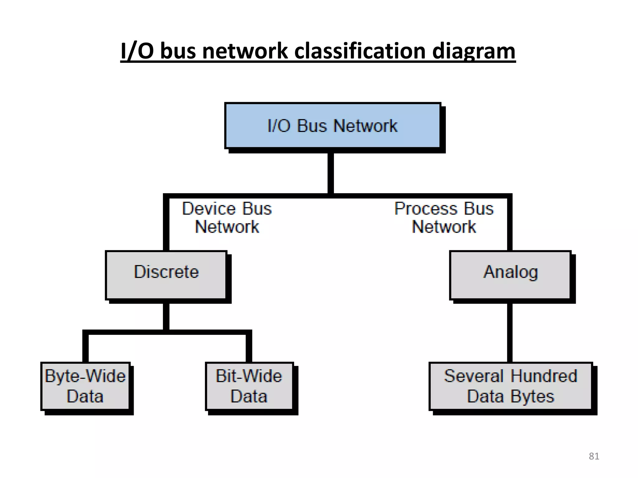
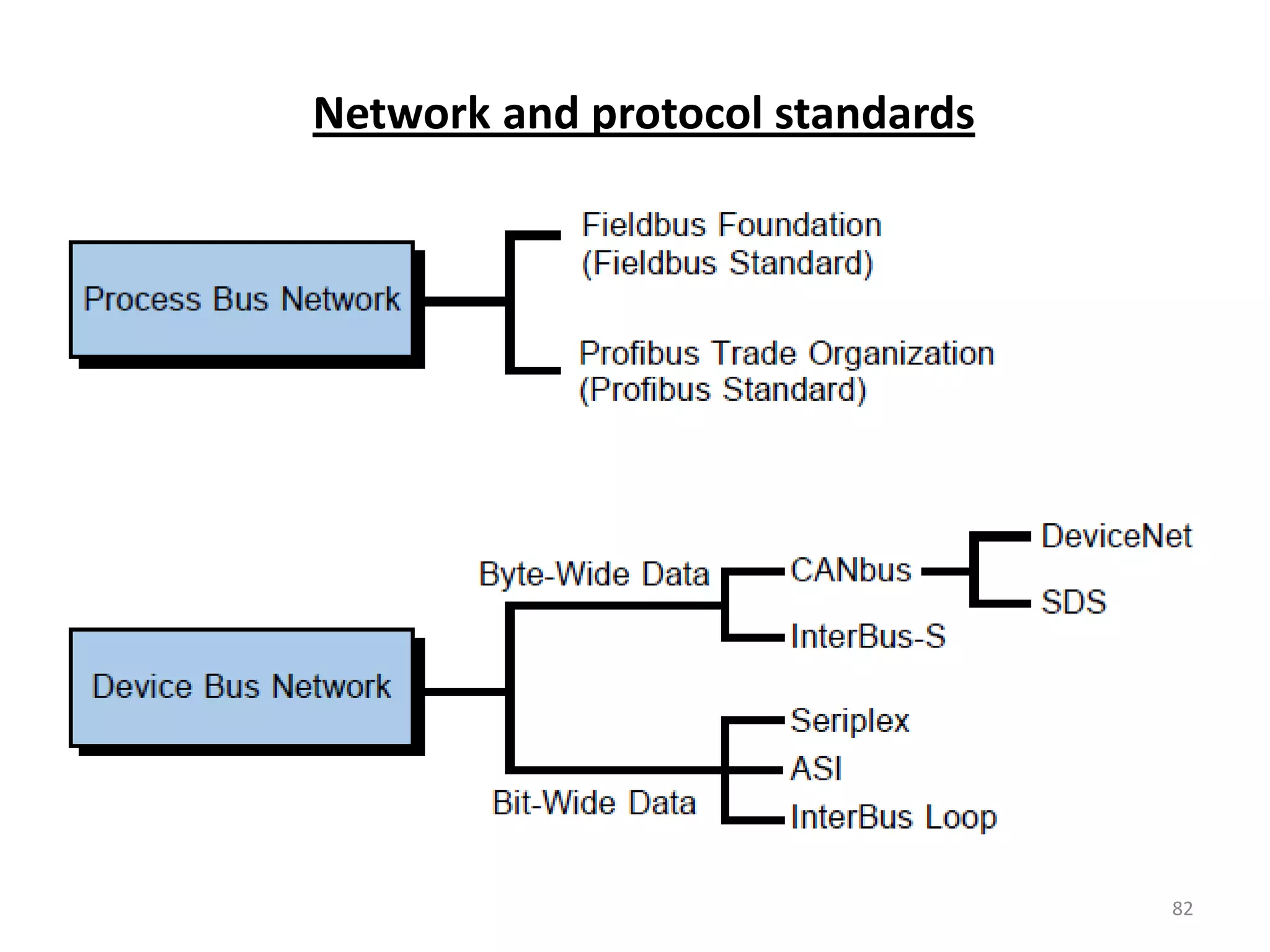
Explains types and classifications of I/O bus networks, including various technologies used.