Download as PDF, PPTX
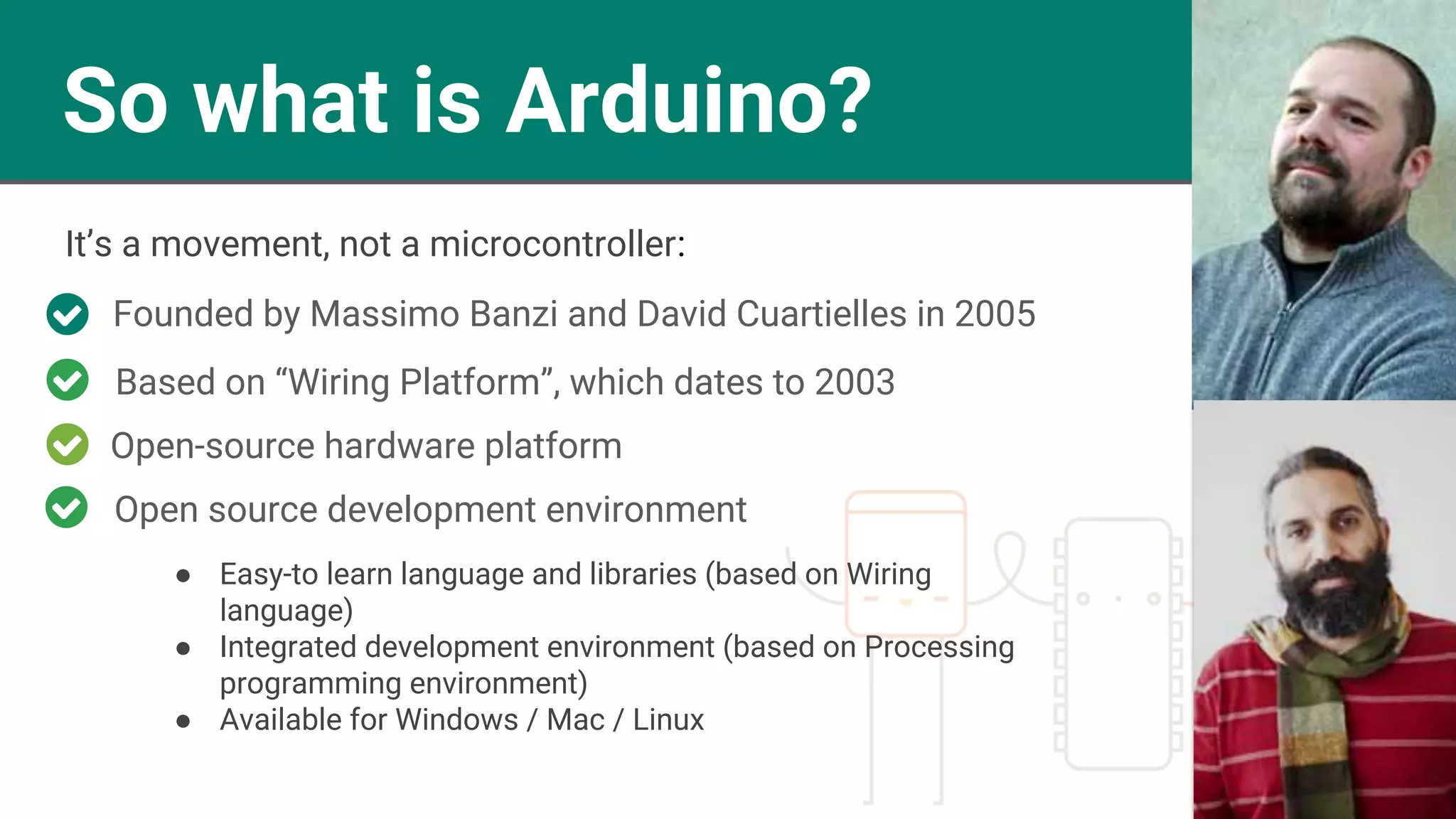
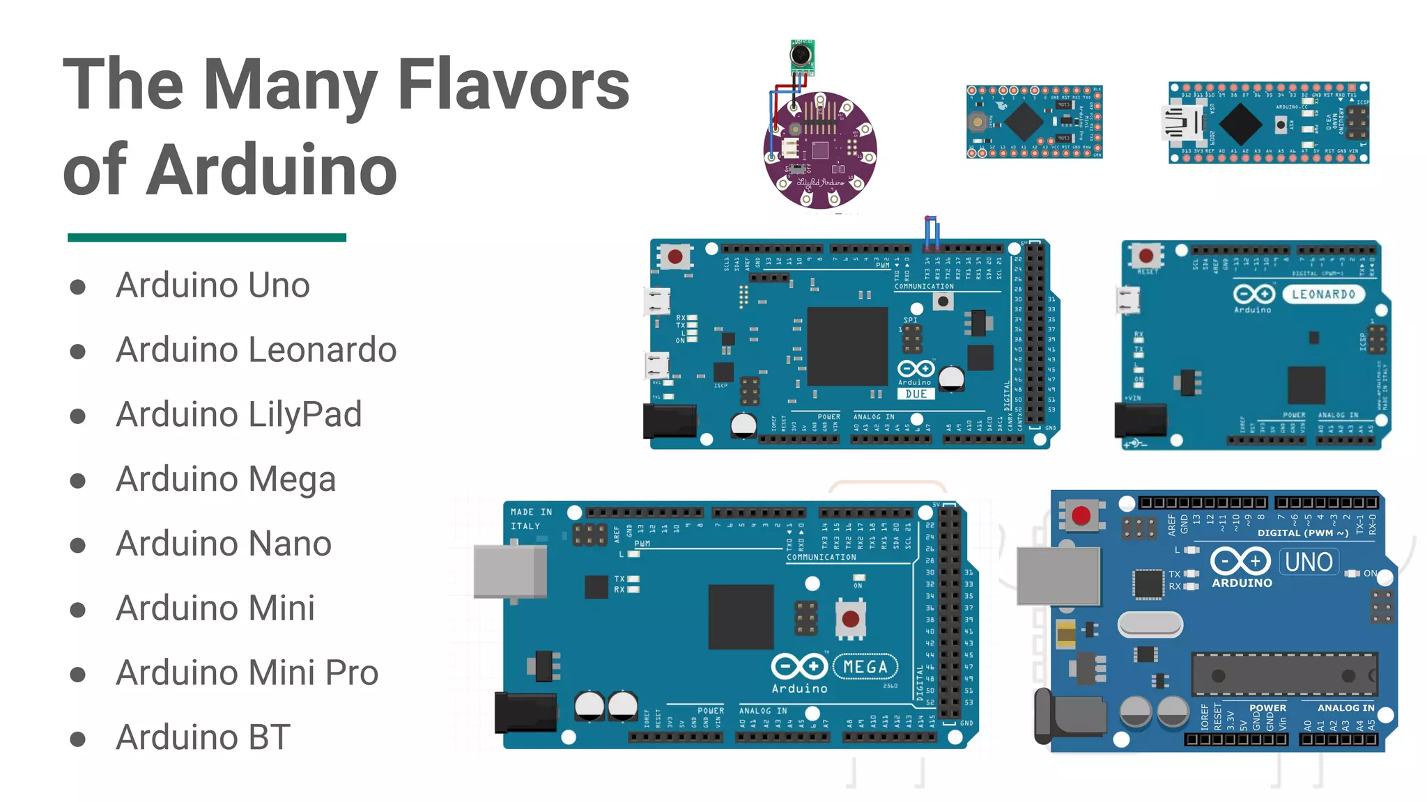
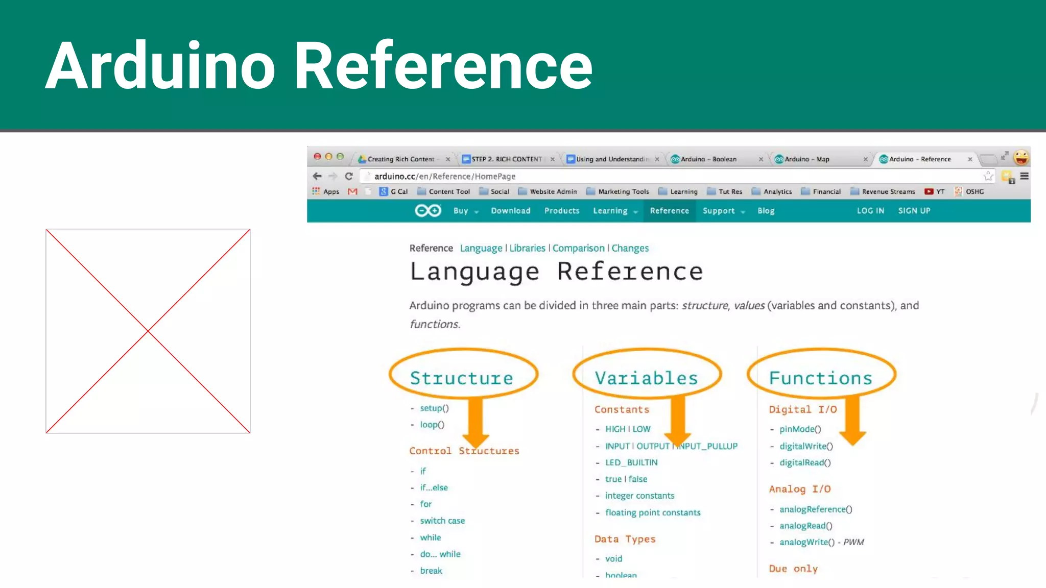
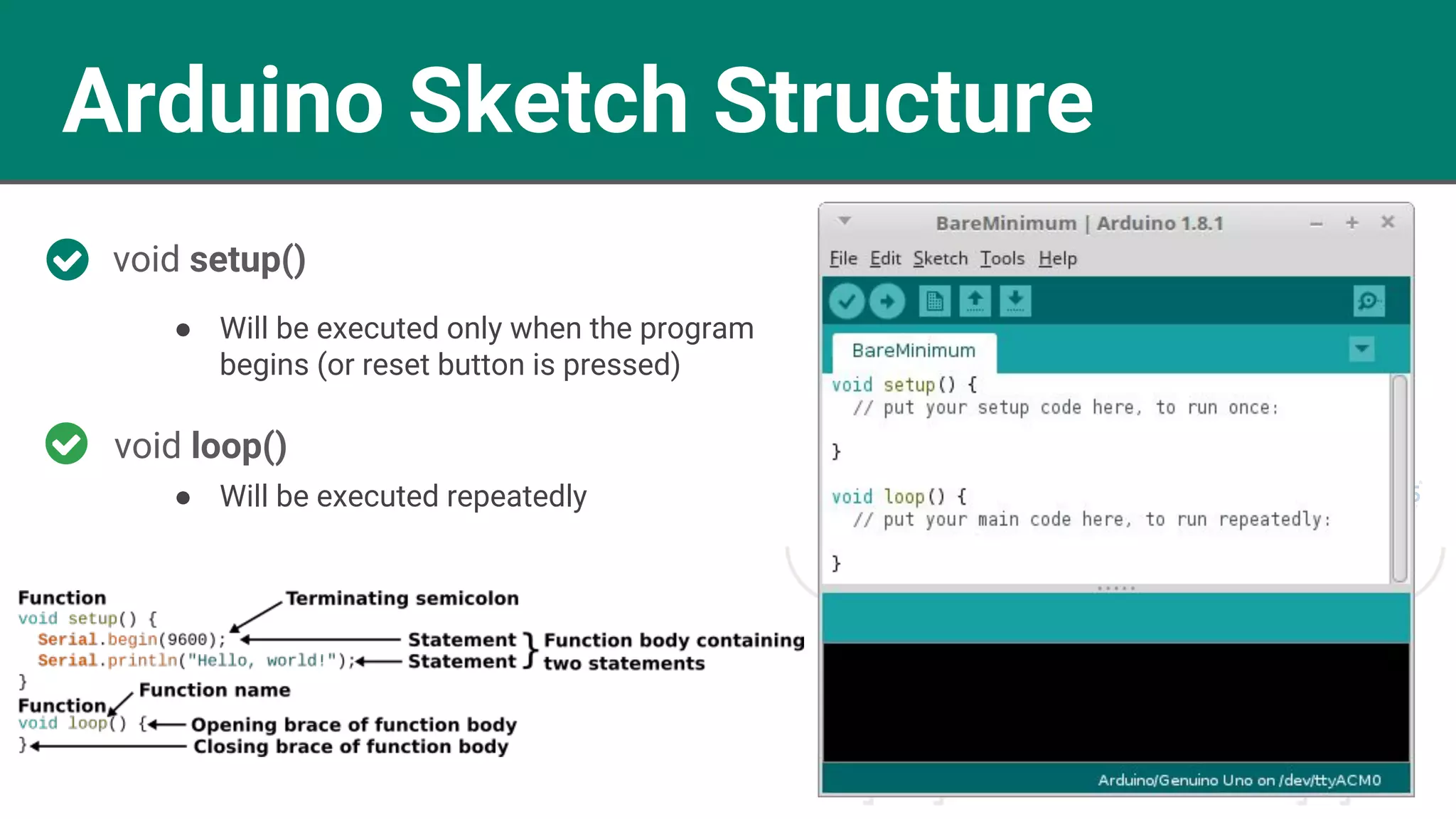
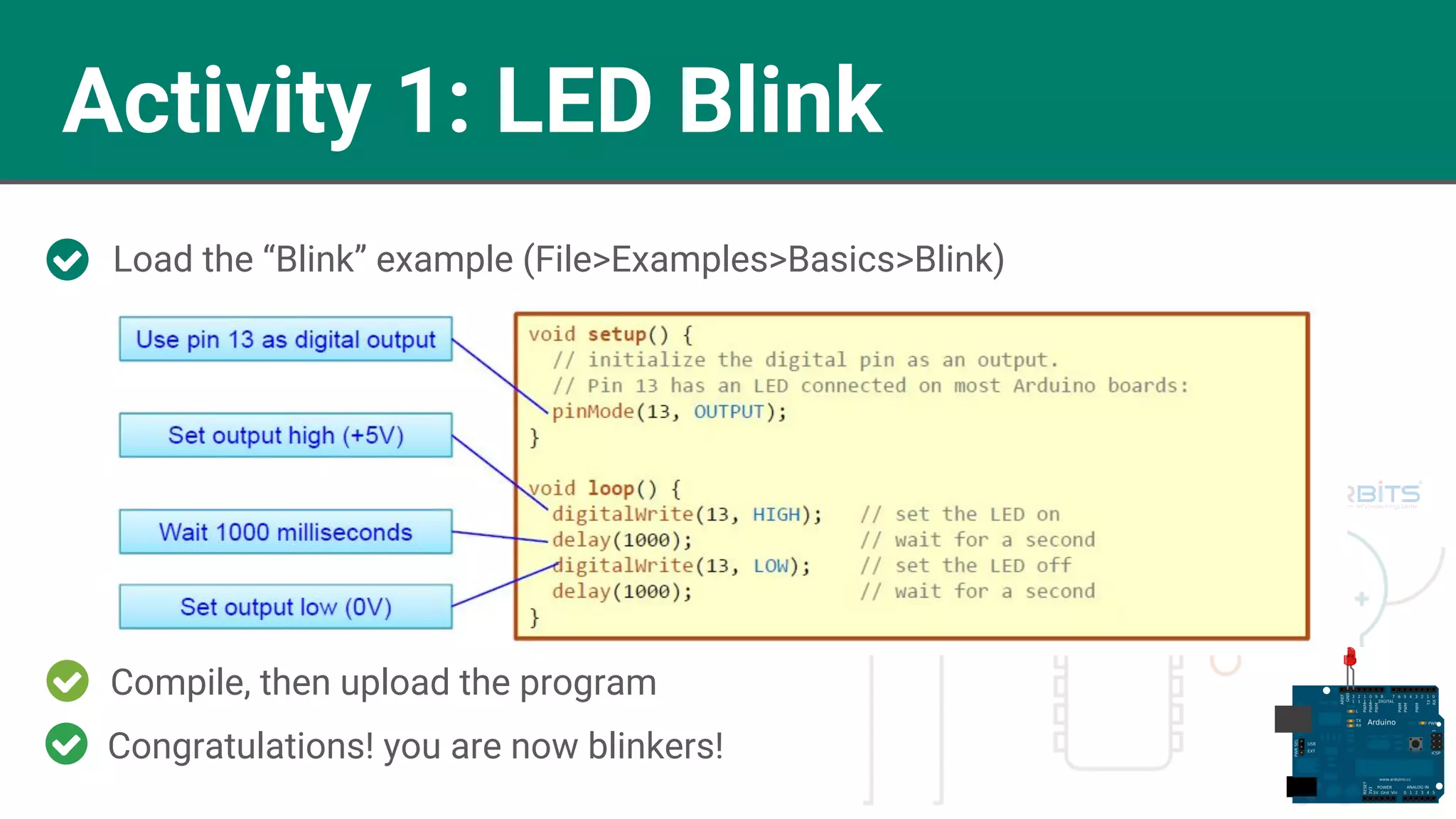
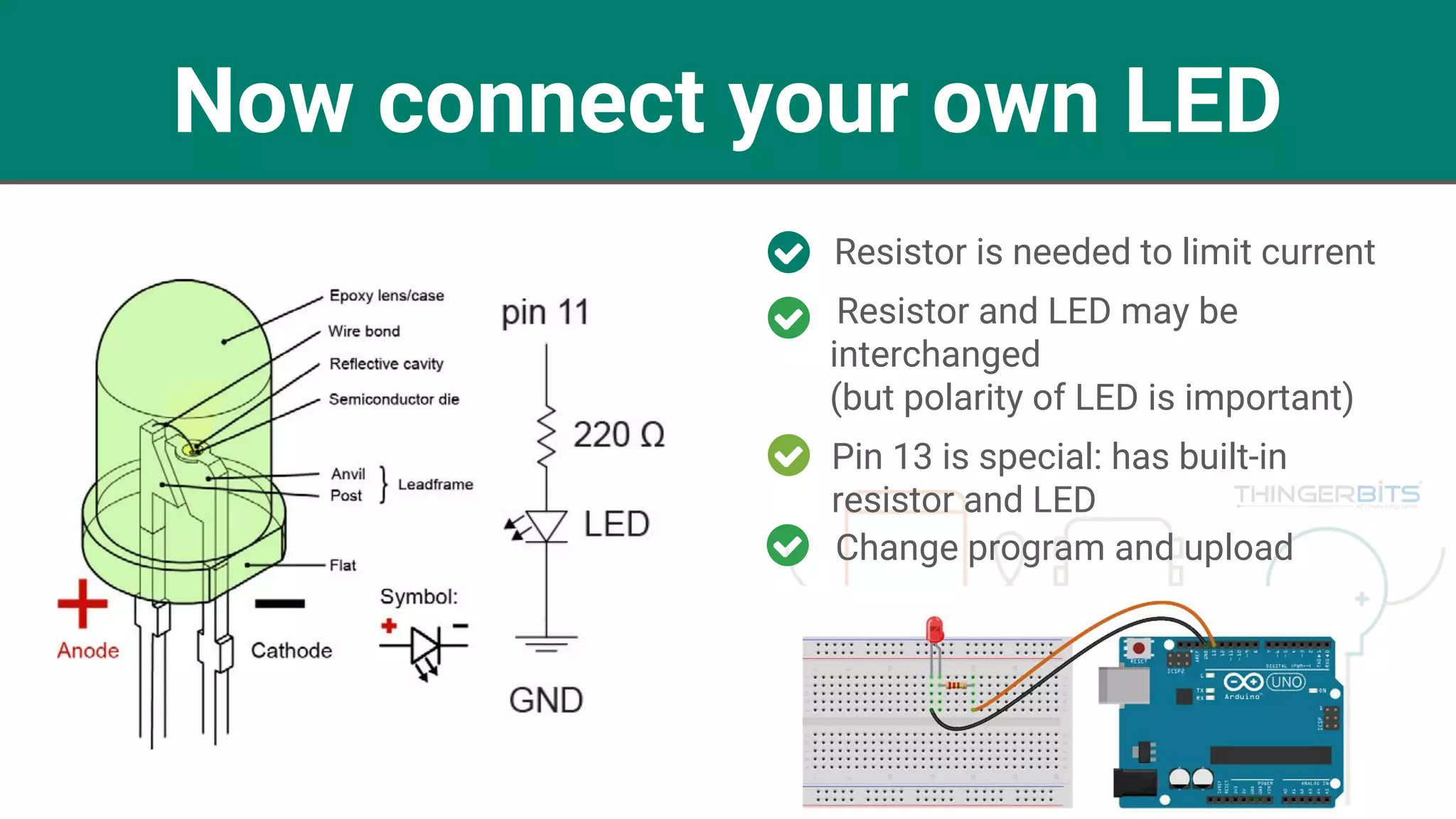
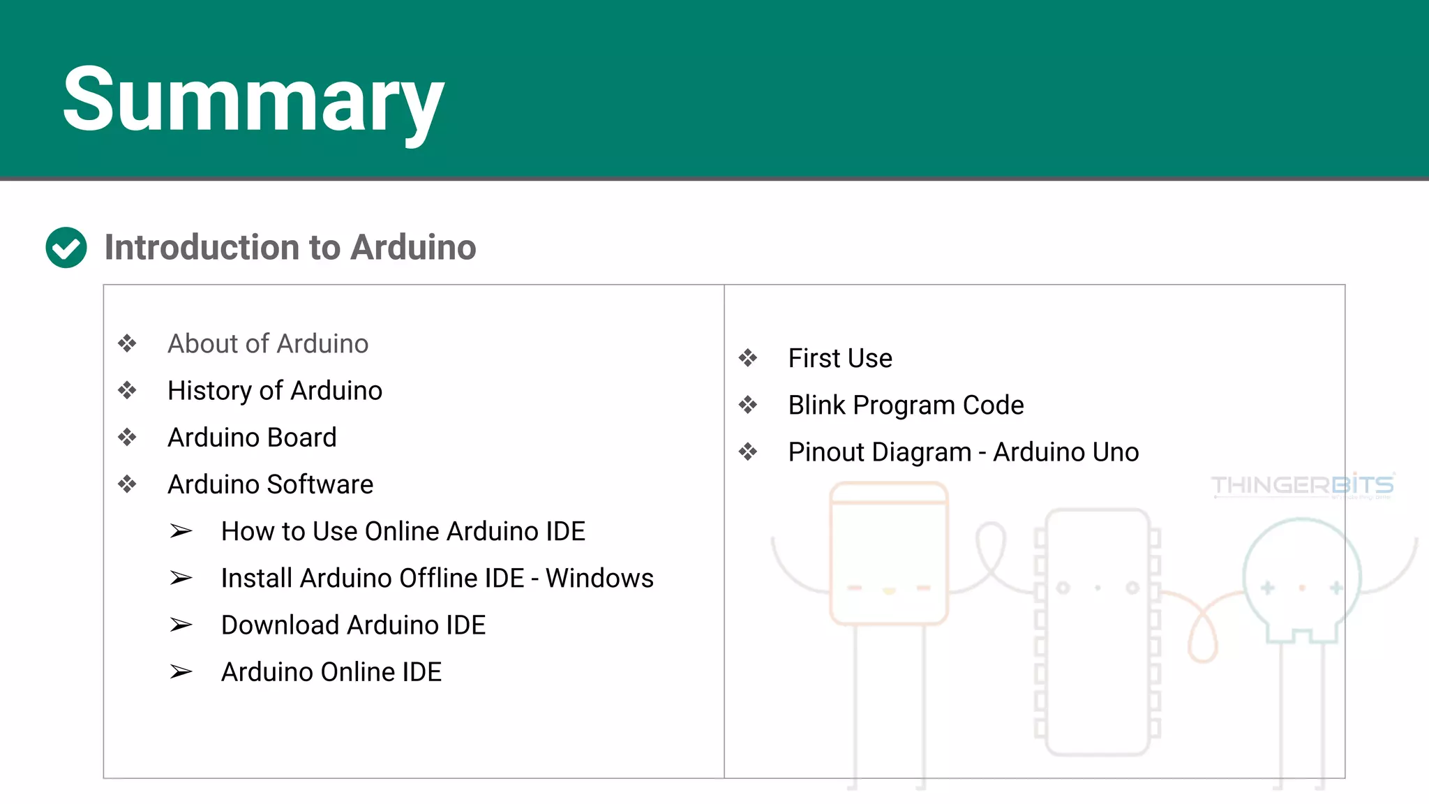

The document provides an introduction to Arduino, detailing its history, architecture, components, and software. It explains the features of the ATmega328P microcontroller and outlines the various Arduino boards and their interfaces. Instructions are also provided for using the Arduino IDE, including uploading code and conducting initial projects like the LED blink program.