This document proposes a method for improving network throughput in software defined networking using multiple best path routing. It summarizes an algorithm that uses depth-first search to find multiple available paths between source and destination, then selects the top n best paths based on link utilization. Traffic is distributed across the multiple best paths using Open vSwitch group tables. Simulation results show the proposed method can outperform shortest path routing in terms of network throughput by utilizing more network resources and paths. However, in networks with heterogeneous path capacities, the throughput improvement is not significant due to bottlenecks on lower capacity paths.
![Improving End-to-End Network Throughput Using Multiple Best Paths Routing in Software Defined Networking Widhi Yahya, Achmad Basuki, Wildan Maulana S., Sabriansyah Rizqika Akbar, Adhitya Bhawiyuga Information Centric Network Research Group Faculty of Computer Science University of Brawijaya Malang, Indonesia E-mail: [email protected], [email protected], [email protected], [email protected], [email protected] Abstract— The use of shortest path algorithms for routing a packet in the network has a tendency to elect only one single best path, even though there are several paths that have same best path criteria. Using only one best path may cause a bottleneck in the networks. This paper proposes a method to utilize multiple best path based on link utilization in order to increase end-to-end network throughput. The method uses DFS (Depth-First Search) algorithm to find all available paths and elect the n best paths based on link utilization. To distribute the traffic across multiple selected best paths, the group action feature of Open vSwitch is utilized. The test result shows that the proposed method can outperform the Dijkstra’s shortest path algorithm in network throughput.](https://image.slidesharecdn.com/improvingend-to-endnetworkthroughputusingmultiplebestpa-221015131047-b1ed5581/75/Improving-End-to-End-Network-Throughput-Using-Multiple-Best-Pa-docx-1-2048.jpg)
![Keywords— Multipath, Routing, OpenFlow, Depth-First Search I. INTRODUCTION The routing protocols play an important role in determining the best paths on the Internet packet delivery process. Some routing protocols utilized shortest path algorithm in determining the path for packet delivery. The algorithms implemented in the router control plane in the form of distributed application [1]. The most widely used shortest path algorithms are the Dijkstra and the Bellman fords. The term “shortest” in determining path brings a new problem. The shortest-path algorithm prunes the network topology become one shortest-path tree(SPT). On heavy network traffic, using one path would cause a bottleneck because the traffic is accommodated by a single path. In the computer network, links and packet switching devices are kinds of resources that are used to move packets from source to destination. Pruning network topology into a single path, such as shortest-path could limit the use of available resources. This pruning process can have an impact on the network throughput. Some studies, [2][3], improve the network throughput by utilizing multipath routing. By using multipath routing, Multiple resources will accommodate a tremendous amount of traffic. Actually, in the current Internet routing protocol such as an OSPF, has already implemented multipath. But the OSPF multipath, called Equal Cost Multipath Technique (ECMP), activated only if equal cost path founded[4]. Development of new routing protocols in current network architecture meets reluctance because the control plane of network devices locked by the vendors. The Software Defined](https://image.slidesharecdn.com/improvingend-to-endnetworkthroughputusingmultiplebestpa-221015131047-b1ed5581/75/Improving-End-to-End-Network-Throughput-Using-Multiple-Best-Pa-docx-2-2048.jpg)
![Networking (SDN) paradigm which separates the control and the data plane, has realized more elastic control plane. The SDN control plane has an API that enables a network administrator to program and implement their protocols on the network switches. The communication between the control plane and the data plane takes place using the OpenFlow protocols (OFP). Having the global information of network topology is one of the important features of the SDN controllers. This information could be used to determine the best path[5]. The SDN paradigm stimulates the emergence of prototypes of new routing protocols. Some research attempts to build a new shortest-path based routing protocol such as [6], [7]. In the built-in protocol, modifications are made to conventional algorithms such as the Dijkstra’s and Floyd Warshall’s. However, when traffic is increased and cannot be handled by a single path, some alternative paths need to be selected. In the study [2], propose the use of alternative path if only the primary path(the best one) has reached its threshold. But in this study has not discussed how many alternative paths are selected and used. In subsequent research on multipath, [8], extend the Dijkstra shortest-path algorithm to find multiple paths. However, in the study, there is the possibility of finding only one path, if another path crossed a path that has been found in the first loop of the extended Dijkstra algorithm. In this study, a multipath routing protocol is realized by selecting the multiple best path. The best path criteria are determined by using controller’s topology information and the real-time traffic information that derived from the Sflow application. Furthermore, the flows will be distributed to the multiple best paths to improve network throughput. The remainder of this paper is organized as follows. Section 2 describes routing, multipath routing and recent research on multipath routing. The protocol design is defined in section 3.](https://image.slidesharecdn.com/improvingend-to-endnetworkthroughputusingmultiplebestpa-221015131047-b1ed5581/75/Improving-End-to-End-Network-Throughput-Using-Multiple-Best-Pa-docx-3-2048.jpg)
![The section 4 and 5 represent the simulation and the simulation results respectively. The study conclusions are found in section 6. II. MULTIPATH ROUTING IN SOFTWARE DEFINED NETWORKING On a computer network, the switching device refers to a device that performs a process of moving packets from input port to the output port. The goal is to deliver packets from one host to another host. If necessary, The packet will traverse 2018 10th International Conference on Information Technology and Electrical Engineering (ICITEE) 978-1-5386-4739-4/18/$31.00 ©2018 IEEE 187 through multiple switching devices to go to the remote host. In this case, The routing protocols play a role in the establishment and the selection of paths in the packet delivery process. The conventional routing protocols run in the network box as distributed applications. The routing protocols placed in the control plane of the network devices. The control plane must have the information and the abstraction of the network topology. This information obtained by using the advertisement message of routing application. Then, the information is processed with the routing algorithm to find the best path[1]. The commonly used algorithm in the routing protocols is the shortest path algorithm. This algorithm prunes the graph into a tree which has only one path from a source to destination(s). This algorithm omits the alternative network resources (link and network devices) in the process of delivering packets from](https://image.slidesharecdn.com/improvingend-to-endnetworkthroughputusingmultiplebestpa-221015131047-b1ed5581/75/Improving-End-to-End-Network-Throughput-Using-Multiple-Best-Pa-docx-4-2048.jpg)
![a source to a destination. This mechanism can cause one shortest-path will suffer if a considerable measure of the flow passes. The development of new protocols on the current network architecture is very complicated because of the limited (no) API to organize the data plane independently. Aiming at this problem, the software-defined network architecture has arisen as a solution. This paradigm proposed to enable network campus innovation by decoupling the data and the control plane. The control plane is the logic of how the packet is forwarded, while the data plane is where the forwarding process takes place. The centralized and programmable control plane drives innovation in computer network protocols. It also triggers research related to multipath routing. In the study, [2], developed the multipath routing extend with rate adaptation, rerouting, and admission control. In this study path obtained by utilizing Depth First Search (DFS) algorithm, but has not specified the number of paths. The rerouting function is called if the traffic on the main path reaches 80%. Another study,[8], utilized Dijkstra algorithm to find multiple paths. The focus is on finding the disjoint path from the network topology. Fig. 1. Group Table[9] This study proposed a routing protocol that utilizes the n best path. The n best paths are obtained by using DFS algorithm. The best means the links with the least utilization. The link information is derived from the Sflow application and the controller’s topology information. The Group entries are used to enable multiple actions for network flows.](https://image.slidesharecdn.com/improvingend-to-endnetworkthroughputusingmultiplebestpa-221015131047-b1ed5581/75/Improving-End-to-End-Network-Throughput-Using-Multiple-Best-Pa-docx-5-2048.jpg)
![III. PROTOCOL DESIGN In this section, we present our design architecture and protocols. Fig 2. Illustrated the OpenFlow system architecture that separate control plane and data plane. The developed system uses OpenFlow 1.3 as communication protocols between the data plane and the control plane. The Openflow 1.3 has Group table features to enable multipath routing[10]. The control plane, also called the SDN controller, runs multipath routing based on DFS algorithm as pathfinding. The data plane is component where the pipeline process takes place. The current link traffic information is currently obtained from the Sflow application. Fig. 2. Components of SDN Architecture A. Multiple Path Searching In this study, the DFS (Depth-First Search) algorithm is used in the path search process. The DFS is a graph algorithm that based on backtracking technique. The algorithm starts at the root, then travel to reach the leaves before backtracking process. The Fig. 3 shows the DFS algorithm. 1: 2: 3: 4:](https://image.slidesharecdn.com/improvingend-to-endnetworkthroughputusingmultiplebestpa-221015131047-b1ed5581/75/Improving-End-to-End-Network-Throughput-Using-Multiple-Best-Pa-docx-6-2048.jpg)
![5: 6: 7: 8: 9: 10: 11: 12: 13: 14: DFS(G, src, dst) P array to store paths (p) stack initialized as (src, [src]) while stack is not empty pop stack, save to node, p for next in (G[node] – p) if next is dst append p + [next] to P else push (next, p + [next]) to stack end for end while return P end Fig. 3. Path Searching Algorithm: DFS In Fig 3, G denotes an adjacency matrix of a graph topology. The adjacency matrix is a matrix that stores the neighbouring information of a node in a topology. The algorithm will find all paths that can be passed from source node s to destination node d. 2018 10th International Conference on Information Technology and Electrical Engineering (ICITEE)](https://image.slidesharecdn.com/improvingend-to-endnetworkthroughputusingmultiplebestpa-221015131047-b1ed5581/75/Improving-End-to-End-Network-Throughput-Using-Multiple-Best-Pa-docx-7-2048.jpg)
![�!�� � "�#$ ����������������������������������� ����������%� C. Selection of n-best paths The best path refers to the path with the least weight. First, the path is sorted by the path’s weight in ascending order. Then select the top n path. n is defined by the administrator in the variable max_path of the program. Then Group Table and the action bucket features are used to forward flows into multiple ports. The Open vSwitch distribute flows among multiple paths using the hash algorithm.[11] IV. SIMULATION TESTING The proposed multipath routing was implemented on Mininet emulator. The OVS that support Openflow version 1.3 was used as the SDN switch. The Sflow agent was also enabled on the switch to collect traffic information on the network. Ryu was used as the SDN controller. The flows were generated by using Iperf. Fig. 4. Topology 1 The functional testing of multipath routing was conducted on topology 1. The topology 1 has three available paths from source(s) to destination(s). In accordance with the hypothesis, on the topology 1, will be proved that the multipath routing will utilize n best path. While the single path routing only uses a shortest-path. The performance testing was conducted in](https://image.slidesharecdn.com/improvingend-to-endnetworkthroughputusingmultiplebestpa-221015131047-b1ed5581/75/Improving-End-to-End-Network-Throughput-Using-Multiple-Best-Pa-docx-9-2048.jpg)
![topology 2 which represents a part of the real network topology of research universities in Indonesia [12]. Topology 2 has a heterogeneous path capacity. In the topology 2, performed observation of multipath routing performance and compare it with the Dijkstra’s shortest-path algorithm. Fig. 5. Topology 2: Java-Sumatera Campus Network Topology based on Indonesia Higher Education and Research Network 2011 V. SIMULATION RESULT Fig. 6 shows the result of the test performed on the topology 1. Testing was conducted to find out the paths utilized by each routing protocol. In the testing process, 40 flows were generated from hosts in the switch 1 (s1) to the hosts in the switch 6 (s6). The BWM-NG application was used to monitor each link usage. The results show that the multipath routing mechanism could utilize 3 best paths, and the resulting throughput is higher than the shortest-path’s. The multipath routing could use all available resources (switching devices and links) to move packets from source to destination. On the contrary, the shortest-path routing limited to only use one best path. TABLE I. MAX PATH VS CONVERGENCE TIME Defined Max Path Paths Found](https://image.slidesharecdn.com/improvingend-to-endnetworkthroughputusingmultiplebestpa-221015131047-b1ed5581/75/Improving-End-to-End-Network-Throughput-Using-Multiple-Best-Pa-docx-10-2048.jpg)
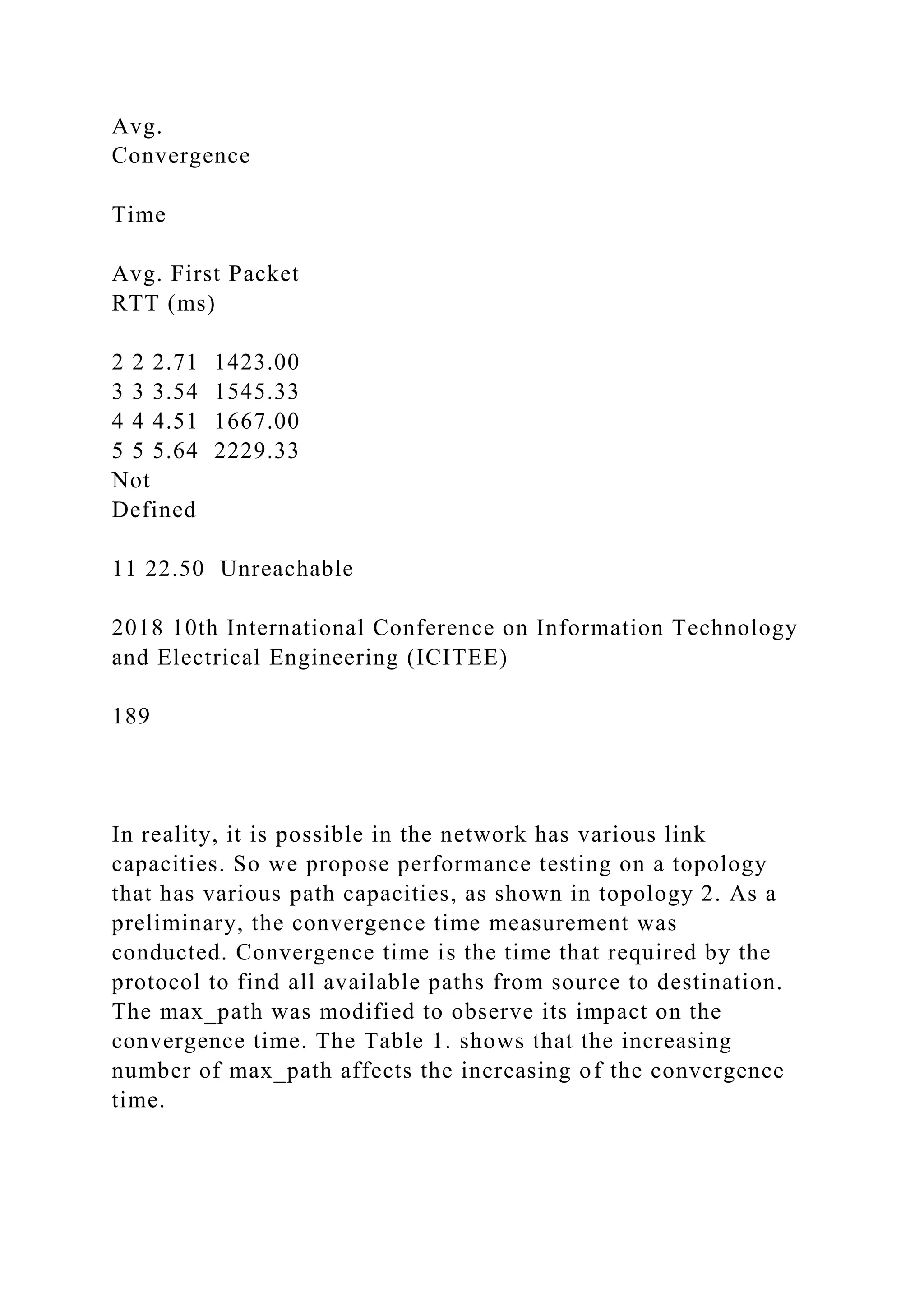
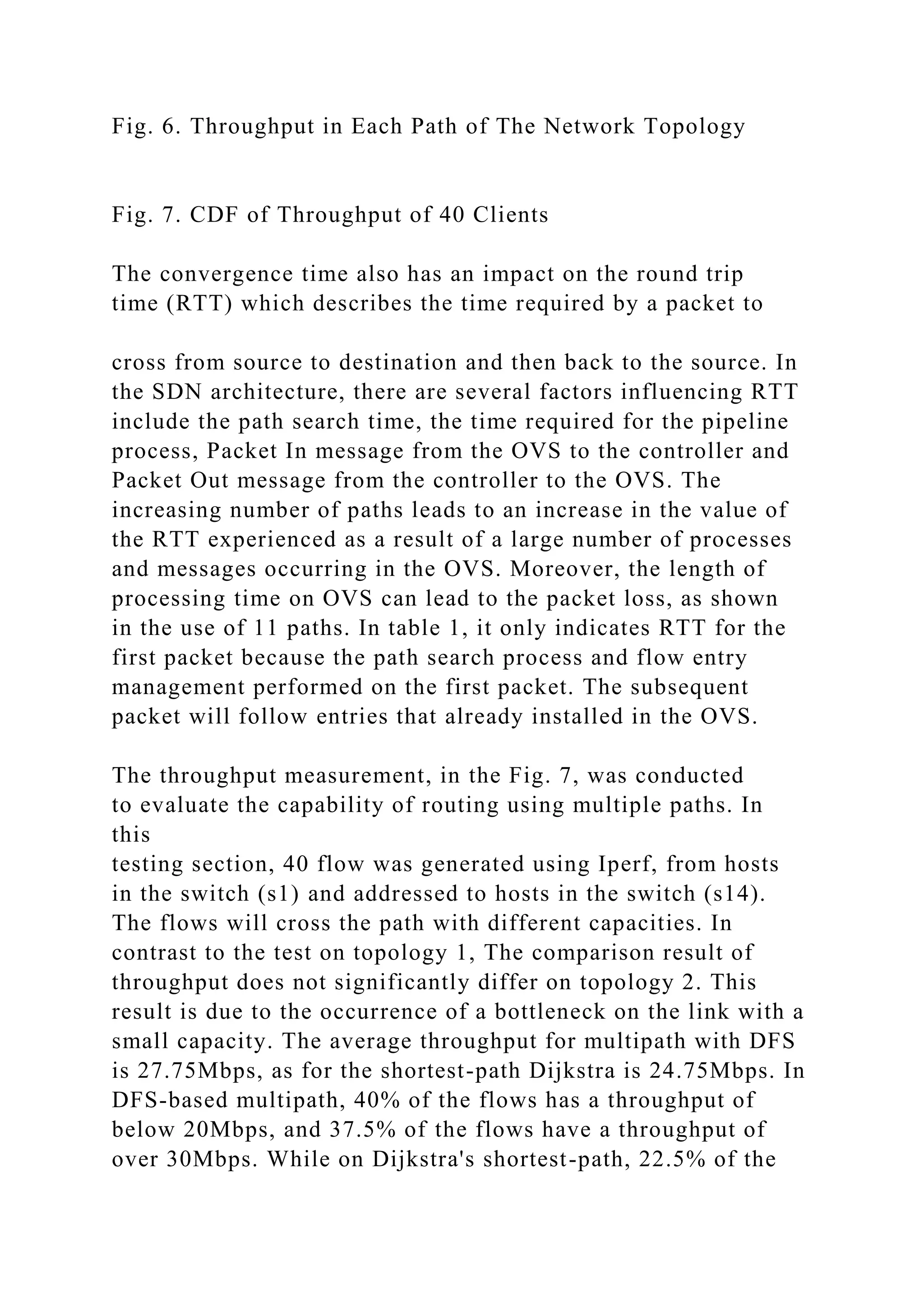
![flows have throughput below 20Mbps and only 17.5% of the flows have throughput above 30Mbps. Some traffic on multipath suffers because it passes through low capacity paths. In the Fig. 8 is an example of the selected path that shown in the controller’s log, on topology 2. Fig. 8. Three Best-Selected Paths Shown in Controller Log VI. CONCLUSIONS This research has implemented multipath routing based on DFS algorithm and the n best paths selection function. The throughput measurement shows that multipath routing’s throughput is superior to single path routing in a controlled and homogeneous environment. In environments that have heterogeneous path capacities, the throughput is not significantly different. The testing results show that the number of paths affects the convergence and OVS processing time. An excessive amount of utilized paths, resulting in the packet loss due to timeout. REFERENCES [1] K. W. R. James F. Kurose, Computer Networking: a Top- Down Approach. 2012. [2] S. N. Hertiana, “A Joint Approach to Multipath Routing and Rate Adaptation for Congestion Control in OpenFlow Software Defined Network,” page. 1–6, 2015. [3] X. Lin, N. B. Shroff, dan S. Member, “Utility Maximization](https://image.slidesharecdn.com/improvingend-to-endnetworkthroughputusingmultiplebestpa-221015131047-b1ed5581/75/Improving-End-to-End-Network-Throughput-Using-Multiple-Best-Pa-docx-13-2048.jpg)
![5, page. 766–781, 2006. [4] C. Villamizar, “OSPF Optimized Multipath (OSPF-OMP),” Internet Engineering Task Force, INTERNET-DRAFT, 1999. . [5] N. Mckeown, T. Anderson, L. Peterson, J. Rexford, S. Shenker, dan S. Louis, “OpenFlow�: Enabling Innovation in Campus Networks,” vol. 38, no. 2, page. 69–74, 2008. [6] J. Jiang, H. Huang, J. Liao, dan S. Chen, “Extending Dijkstra ’ s Shortest Path Algorithm for Software Defined Networking,” 2014. [7] A. G. Furculita, M. V. Ulinic, A. B. Rus, dan V. Dobrota, “Implementation issues for Modified Dijkstra’s and Floyd- Warshall algorithms in OpenFlow,” Proc. - RoEduNet IEEE Int. Conf., 2013. [8] Y. Chiang, C. Ke, Y. Yu, Y. Chen, dan C. Pan, “A Multipath Transmission Scheme for the Improvement of Throughput over SDN,” page. 1247–1250, 2017. [9] P. Goransson, C. Black, dan T. Culver, Software Defined Networks: A Comprehensive Approach. Morgan Kaufmann, 2016. [10] Open Networking Foundation, “OpenFlow Switch Specification 1.3.0,” 2012.](https://image.slidesharecdn.com/improvingend-to-endnetworkthroughputusingmultiplebestpa-221015131047-b1ed5581/75/Improving-End-to-End-Network-Throughput-Using-Multiple-Best-Pa-docx-15-2048.jpg)
![[11] “Using OpenFlow — Open vSwitch 2.9.90 documentation.” .Available at: http://docs.openvswitch.org/en/latest/faq/openflow/. [Accessed: 17 May 2018]. [12] Nic.itb.ac.id. (2018). Inherent | ITB Network Information Center. [online] Available at: https://nic.itb.ac.id/inherent [Accessed: 23 Jan. 2018]. 2018 10th International Conference on Information Technology and Electrical Engineering (ICITEE) 191 Convergence time analysis of open shortest path first routing protocol in internet scale networks S.U. Malik, S.K. Srinivasan and S.U. Khan Proposed is a novel method to compute the intra-area convergence time of open shortest path first (OSPF) based networks in the presence of designated routers (DRs) on Ethernet and non-broadcast multi- access segments. The capacity of the proposed method is demonstrated by](https://image.slidesharecdn.com/improvingend-to-endnetworkthroughputusingmultiplebestpa-221015131047-b1ed5581/75/Improving-End-to-End-Network-Throughput-Using-Multiple-Best-Pa-docx-16-2048.jpg)
![evaluating the convergence time performance of OSFP on internet scale networks (having a thousand autonomous system level routers). The method has also been used to analyse the effects of: (a) the number of DRs, (b) cascading failures, and (c) topological changes on the convergence time of the routers within an area. Furthermore, the time the network takes from a cold state to reach a stable (steady) state in an area is also analysed. Introduction: Open shortest path first (OSPF) is an adaptive routing protocol to distribute routing information within a single autonomous system (AS) [1]. OSPF divides the network into areas. Each area consists of one or more segments. A segment constitutes the set of routers con- nected via a common communication channel (example Ethernet). When a failure occurs, topologies are regenerated and paths are recalcu- lated by all of the routers within that area [2]. The time a router takes to discover the area topology is known as the convergence time [1]. To improve the convergence time of a segment in an area, a router is selected as a designated router (DR) on each segment. Fast convergence time is required to meet network based application demands and quality of service (QoS) requirements of modern](https://image.slidesharecdn.com/improvingend-to-endnetworkthroughputusingmultiplebestpa-221015131047-b1ed5581/75/Improving-End-to-End-Network-Throughput-Using-Multiple-Best-Pa-docx-17-2048.jpg)
![dynamic large-scale routing domains, such as data centres. Therefore, a lot of effort and studies have been made to improve the performance of OSPF [3]. However, the convergence time analysis of OSPF that incor- porates DRs has never been studied. We address the aforementioned, by developing a novel method to compute the intra-area convergence time of OSPF-based networks that incorporates DRs, which is the primary contribution of this Letter. Moreover, to analyse and benchmark the pro- tocol on internet scale networks is another contribution of this work. We also show how to use our method to study the effect of: (a) DRs, (b) cas- cading failures, and (c) topological changes on the convergence time of the routers within an area. For our experiments, we simulated the detailed implementation of the OSPF protocol based on the specifications reported in [2]. To get realis- tic measurements we generate topologies from BRITE [4], using Otter [4] (as shown in Fig. 1.) that represents the exact same characteristics as those of the internet. The results and analysis provided in this Letter will be extremely useful for network administrators seeking to deploy OSPF. Moreover, the results are also useful in the](https://image.slidesharecdn.com/improvingend-to-endnetworkthroughputusingmultiplebestpa-221015131047-b1ed5581/75/Improving-End-to-End-Network-Throughput-Using-Multiple-Best-Pa-docx-18-2048.jpg)
![behavioural analysis of OSPF and can provide the basis to re-evaluate the design of the protocol to achieve performance optimisation. Fig. 1 Sample topology for one thousand routers Problem formulation: Consider a network composed of N routers. Let Ri be the ith router, where 1 ≤ i ≤ N . A link between two routers Ri and Rj (if it exists) has a communication cost that represents the minimum time for transferring a message from Ri to Rj , which can be represented by the following expression [5]: del(Ri, Rj) = D(Ri, Rj) n + s bij (1) where D(Ri, Rj) is the physical distance between Ri and Rj , n is the propagation delay of the medium (optical fibre in our case), s is the size of the message in kilobytes, and bij is the available bandwidth between Ri and Rj . If the routers are not directly connected, then the communication cost is the sum of the cost of all links in the](https://image.slidesharecdn.com/improvingend-to-endnetworkthroughputusingmultiplebestpa-221015131047-b1ed5581/75/Improving-End-to-End-Network-Throughput-Using-Multiple-Best-Pa-docx-19-2048.jpg)
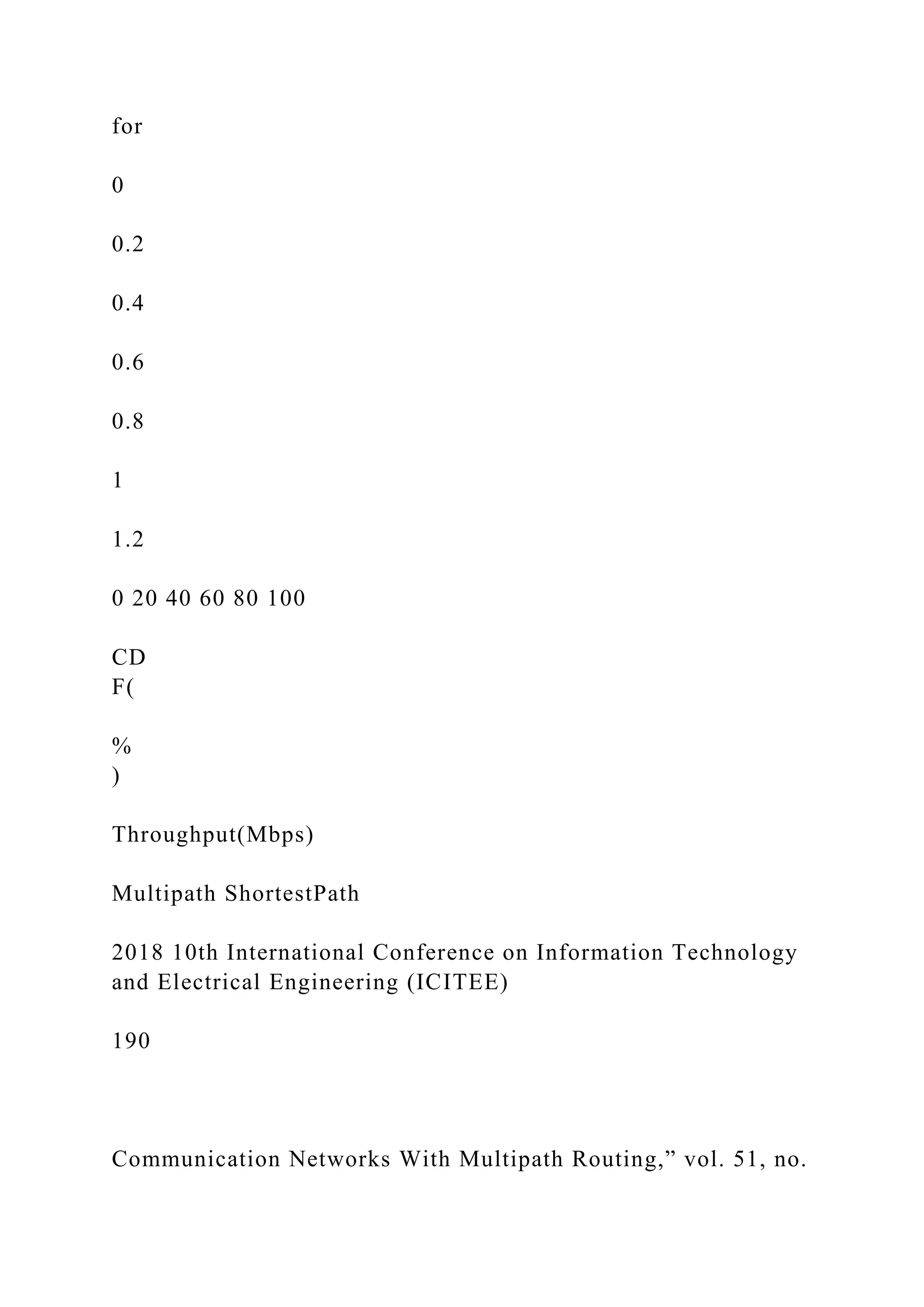
![shortest path from Ri to Rj . Without loss of generality, we assume that ELECTRONICS LETTERS 13th September 2012 V del(Ri, Rj) = del(Rj, Ri), which is a common assumption in the literature [5]. Let M be the number of segments within an area and Sk be the kth segment in that area, where 1 ≤ k ≤ M . Let DS be the set of DRs within an area and 6k is the convergence time of Sk . If a failure occurs (could be a link or a router), the routers connected to the failed link or failed router will initiate the updates. Let Rko be a router that initiates an update in response to a failure. Let Rr be the set of all other routers in the area defined as Rr = ( ⋃N i−1{Ri}){{Rko} < DS}. Rko will detect a failure if no response is received from a neighbouring router for a period longer than the dead interval (DI). Rko will then update its link state and forward the updated link state to the DR of segment k (represented as dk . The link state is the description of the interface of the router (IP address of the interface, mask, type of network, routers con- nected to) and the relationship to other routers. The DR will then flood the information to every other router in the segment after receiving](https://image.slidesharecdn.com/improvingend-to-endnetworkthroughputusingmultiplebestpa-221015131047-b1ed5581/75/Improving-End-to-End-Network-Throughput-Using-Multiple-Best-Pa-docx-20-2048.jpg)
![seconds for all other media [2]. The value of c(Rki ) for Rki [ Rr is the sum of the time required for dk to receive updates and the time dk takes to deliver updates to Rki . The value of c(dk) is calculated in (3), which is the sum of c(Rkk) (the node sending the update to d k ) and the communication cost between them, which is given as del(Rkj , d k). Moreover, (2) and (3) are used to calculate 6k based on the following equation: 6k = max(c(dk) + del∀ j[k(dk, Rkj )) (4) The last router (maximum time taken to receive an update from the cor- responding dk ) in Sk that receives the update, determines 6k . Now, using (2), (3) and (4) the convergence time of an area t can be calculated as follows: t = max∀ k[S((6k )) + c((Rko) + del(R k o, d k) (5) The maximum 6k amongst all of the segments plus the time when the update is initiated and reaches to the respective DR determines](https://image.slidesharecdn.com/improvingend-to-endnetworkthroughputusingmultiplebestpa-221015131047-b1ed5581/75/Improving-End-to-End-Network-Throughput-Using-Multiple-Best-Pa-docx-22-2048.jpg)
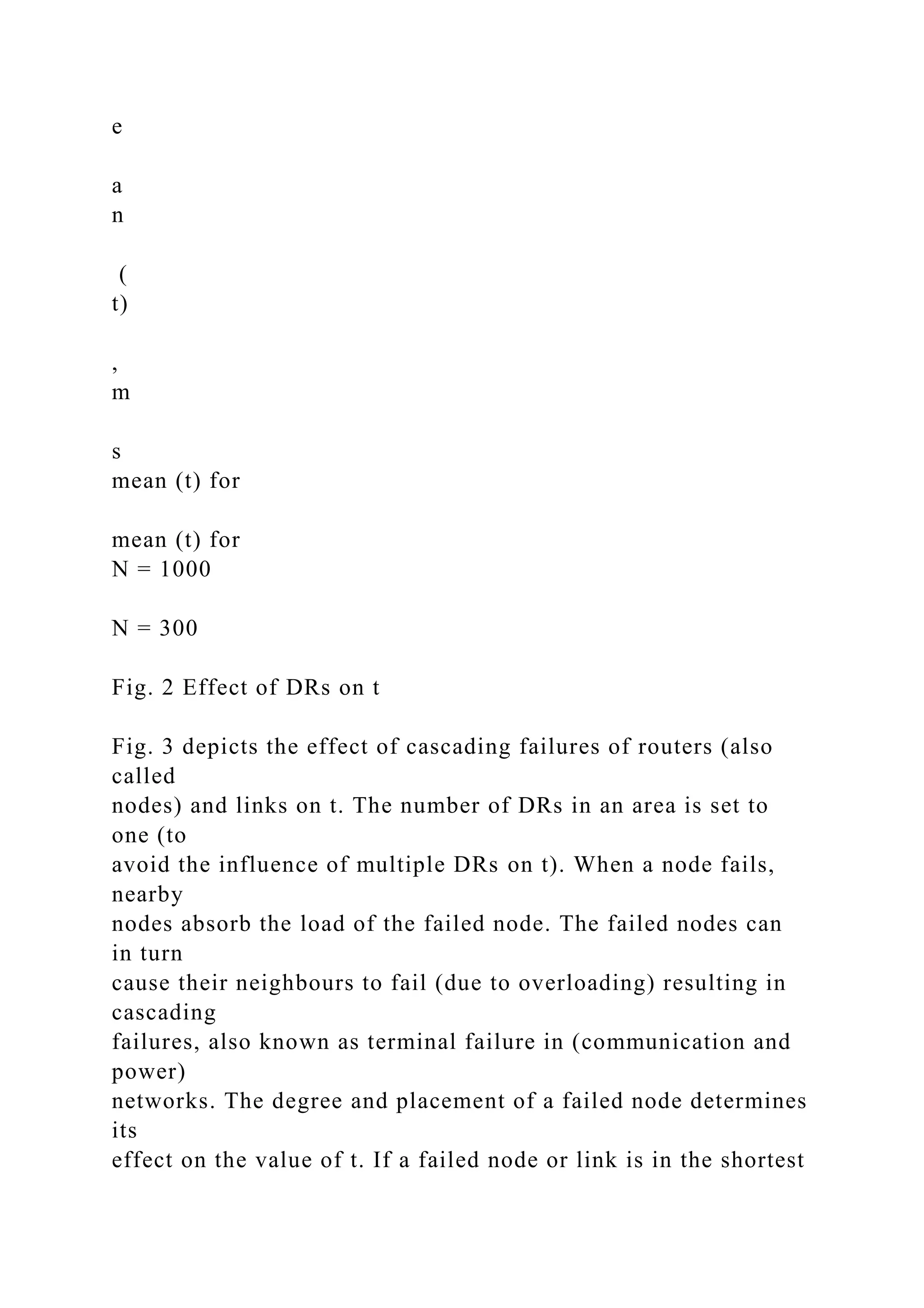
![the value of t. Results and discussion: The value of t determines the time an area requires to reach a stable (steady) state from an unstable state, which is caused by an update. Therefore, to avoid message losses the network must converge quickly. To this end, we evaluate the effect of: (a) the number of DRs, (b) cascading failures, and (c) topology on the value of t. We assume optical fibre as the communication medium having propa- gation delay v = 300 × 106 miles/s. Ethernet channels have a maximum transmit unit (MTU) of 1500 bytes [1]. Also, fragmentation is usually avoided in OSPF [1]. Therefore, we assume the message size s to be 1 KB (lower than the 1500B cap, but not too low and is typically used in the literature for experimentation, such as in [6]). The bandwidth value bij is kept constant at 100 Mbit/s, as advocated in [7] for evalu- ation purposes. The values of D(Ri, Rj) are assigned from within the range of [1 – 100] km. Fig. 2 depicts the effect of the number of DRs on the value of t. To analyse the effect on large and average scale networks, we used N ¼](https://image.slidesharecdn.com/improvingend-to-endnetworkthroughputusingmultiplebestpa-221015131047-b1ed5581/75/Improving-End-to-End-Network-Throughput-Using-Multiple-Best-Pa-docx-23-2048.jpg)
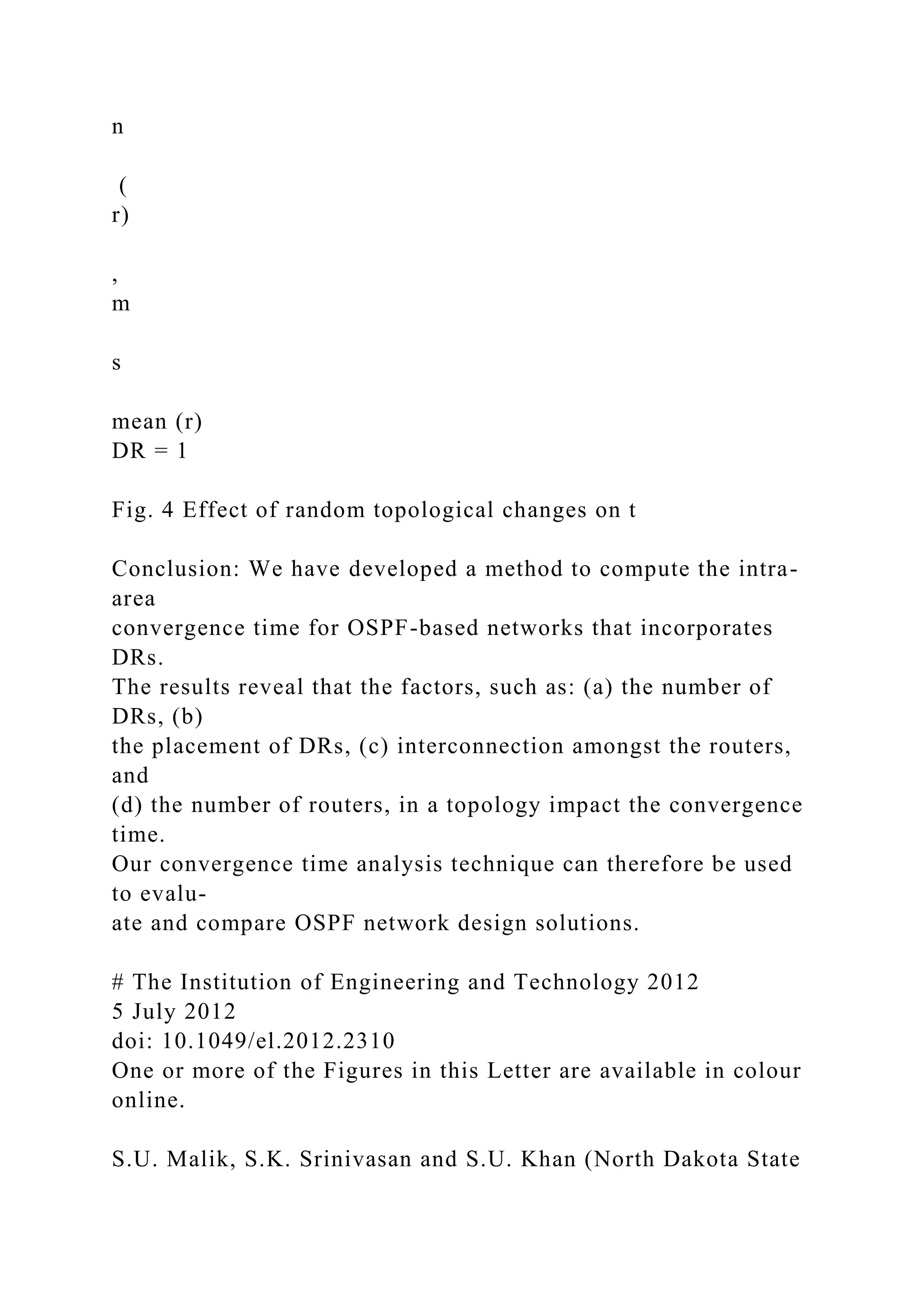
![{1000, 300}. A DR can decrease the segment convergence time from O(n 2) to O(n) [1]. However, including more DRs in an area has no effect or in some cases may even increase the value of t. As reported in Fig. 2, the mean value of t increases gradually as the number of DRs increases in the topology. To see why, consider a router R under DR1. If DR2 is added to the area and R now falls under DR2, then DR1 can no longer directly communicate with R, but instead it is obliga- tory to communicate via DR2. From this example we can see that ol. 48 No. 19 including a DR can increase the length of communication paths in the area, thereby possibly increasing its convergence time. Therefore, the placement of DR is crucial towards the value of t. 0 10 20 30 40 1 10 20 30 40 50 60 70 80 90 100 DR m](https://image.slidesharecdn.com/improvingend-to-endnetworkthroughputusingmultiplebestpa-221015131047-b1ed5581/75/Improving-End-to-End-Network-Throughput-Using-Multiple-Best-Pa-docx-24-2048.jpg)


![University, ND 58108, USA) E-mail: [email protected] References 1 Moy, J.T.: ‘OSPF; Anatomy of an Internet routing protocol’ (Addison- Wesley, 1998) 2 Moy, J.: ‘OSPF Version 2, The Internet Society OSPFv2’, http://www. ietf.org/rfc/rfc2328.txt, accessed on 08 May, 2012 3 Goyal, M., Soperi, M., Baccelli, E., Choudhury, G., Shaikh, A., and Hosseini, H.: ‘Improving convergence speed and scalability in OSPF: a survey’, IEEE ComST, 2012, 14, (2), pp. 443 – 463 4 Medina, A., Lakhina, A., Matta, I., and Byers, J.: ‘BRITE: An Approach to Universal Topology Generation’. MASCOTS, Ohio, 2001 5 Khan, S.U., and Ahmad, I.: ‘A pure Nash equilibrium based game theoretical method for data replication across multiple servers’, IEEE Trans. Knowl. Data Eng., 2009, 21, (4), pp. 537 – 553 6 Wang, B., Zhang, J., Guo, Y., and Chen, W.: ‘Fast-converging distance vector routing mechanism for IP networks’, J. Netw., 2010, 05, (9), pp. 1069 – 1075 7 Prasad, R.S., Murray, M., Dovrolis, C., and Claffy, K.:](https://image.slidesharecdn.com/improvingend-to-endnetworkthroughputusingmultiplebestpa-221015131047-b1ed5581/75/Improving-End-to-End-Network-Throughput-Using-Multiple-Best-Pa-docx-29-2048.jpg)
![OSPF V2 is a link-state routing protocol that employs a version of Dijkstra's shortest path first protocol, and is an open standard. OSPF V2 is defined by the Internet Engineering Task Force in Request for Comments (RFC) 1583 [l]. OSPF allows collections of contiguous networks and hosts to be grouped together. RFC 1583 labels such a group, together with the routers having interfaces to any one of the included networks, an area. OSPF areas are interconnected via a backbone area, which is called area zero. OSPF'requires that IP datagram exchanges between areas must traverse the OSPF backbone area. OSPF V2 is normally used within primarily static corporate networks. Within the tactical environment, communication nodes are mobile and the networks connectivity and associated topology is in a constant state of change. Attrition can also lead to sudden dramatic network topology changes. Also, tactical networks have significant bandwidth constraints. Therefore, the OSPF parameters used for operations in the tactical environment need to be well understood and carefully selected. Routing bandwidth utilization should be minimized. However, the ability to detect, advertise, and route around network outages should be timely. In addition, the grouping of networks within OSPFs hierarchical architecture should be carefully designed to ensure network reconfigurations can be performed with ease. 3.0 OSPF ROUTING PROTOCOL](https://image.slidesharecdn.com/improvingend-to-endnetworkthroughputusingmultiplebestpa-221015131047-b1ed5581/75/Improving-End-to-End-Network-Throughput-Using-Multiple-Best-Pa-docx-31-2048.jpg)
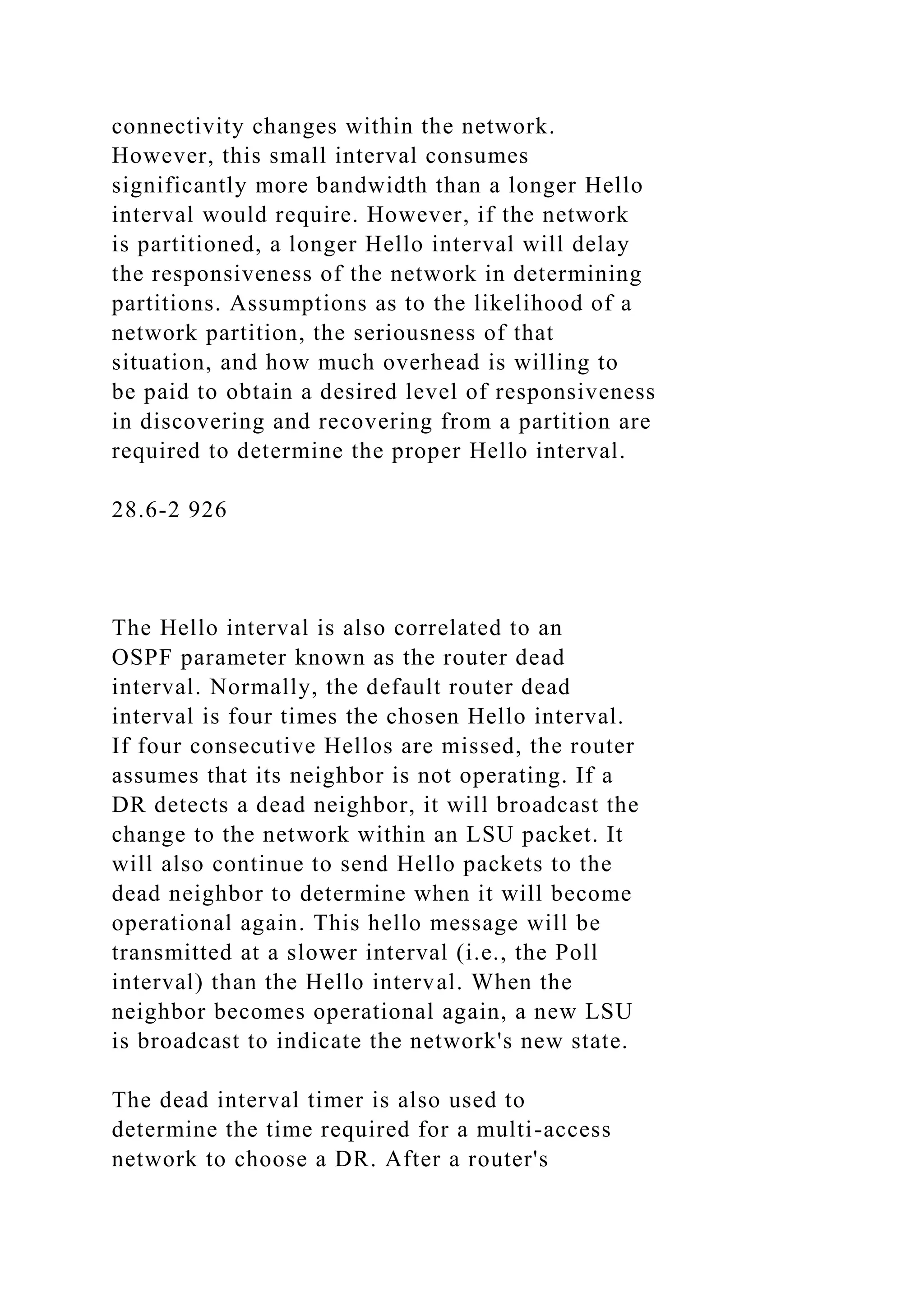
![interface is initially activated on the multi-access network, it will remain in a wait state for a period of time equal to the dead interval timer value. During this period, the router will exchange hello packets with other routers operating on the network. Once this period expires, the router will propose a multi-access network DR based upon multi-access network router priorities and network connectivity, if a DR is not already chosen. Only routers with two way connectivity to the other routers on the network can be elected as the DR or backup DR. By specification, all of the routers communicating across a multi-access network must use the same hello interval and dead interval value. This simplifies OSPFs implementations, but limits flexible network designs. For instance, if different Hello intervals were allowed, OSPF routing overhead could be reduced [ 2 ] . Including the IP header, the Hello packet contains a minimum of 64 bytes. A multiple of four additional bytes are concatenated to the packet to advertise the routers that the source has heard from within the past dead interval period. For transmission across SINCGARS, the IP datagram is then encapsulated within a MIL- STD-188-220( ) envelope, which requires 17 bytes of overhead. For instance, at least 85 bytes are transmitted within every Hello packet if there are two routers operating on the network. These Hello packets are transmitted once in every Hello interval. The Hello interval is a user-defined parameter that can be set to as low as one second. Generally, a higher value would be used. Of](https://image.slidesharecdn.com/improvingend-to-endnetworkthroughputusingmultiplebestpa-221015131047-b1ed5581/75/Improving-End-to-End-Network-Throughput-Using-Multiple-Best-Pa-docx-36-2048.jpg)
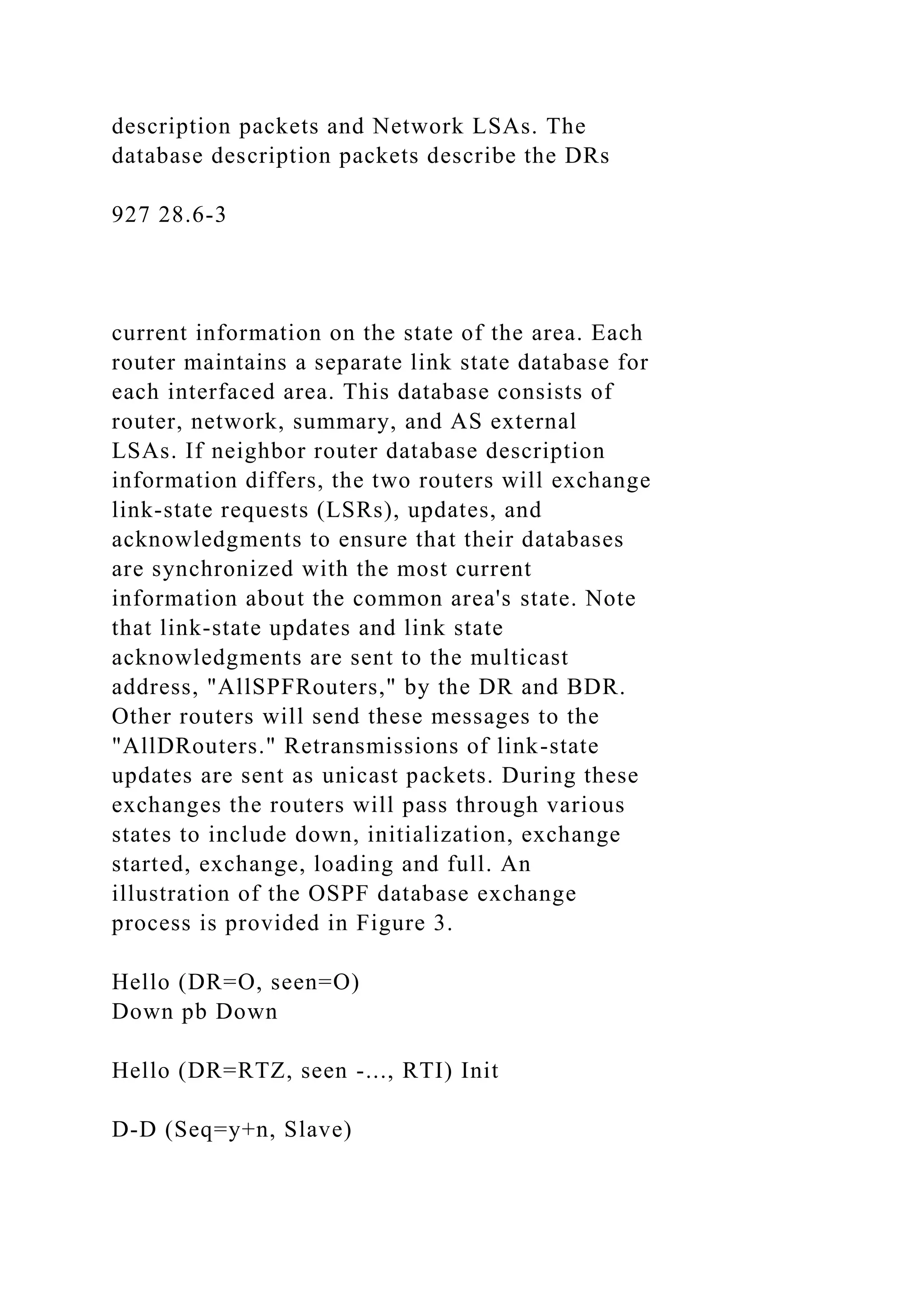
![D-D (Ses=v+n, Master) m Link State Request Link Stare Update b Full Loading Full Figure 3. OSPF Database Description Exchange [l] The database description packet consists of the 24 byte OSPF header and eight additional bytes to support database description packet sequencing and miscellaneous protocol negotiation information. Optimally, the remainder of the packet contains LSA headers for every LSA known to the router. Because each LSA header uniquely describes a particular LSA and its age, an adjacent router can use this information to determine if its database is current. If the router determines that the LSA descriptor is not within its database or has an age less than its matching LSA, the router will request the complete LSA from its neighbor within a LSR packet. Each LSR packet includes an OSPF header and 12 bytes of information, which describe each LSA requested. Each router is only permitted one outstanding LSR packet at any time. The number of LSAs that are required within a database description is dependent on the size and architecture of the network.](https://image.slidesharecdn.com/improvingend-to-endnetworkthroughputusingmultiplebestpa-221015131047-b1ed5581/75/Improving-End-to-End-Network-Throughput-Using-Multiple-Best-Pa-docx-39-2048.jpg)
![minutes[l]. This value can not be changed by the network manager. During initial network operations, it is difficult to characterize the amount of bandwidth required to synchronize router databases. Since routers will be turning on and establishing adjacencies with the DR at different times, the bandwidth required will vary. Also, many events can abort a database description exchange. For instance, if two way hello connectivity is lost at any time during a database description exchange, the exchange is aborted and must start over. Also, reception of out of sequence database description packets will lead to a restart of the database exchange. Lower layer protocol collisions can also hinder the database description exchange [3]. Simulation is required to analyze the different possible effects on the network during these critical periods. 4 . 0 OSPF ARCHITECTURE CONSTRAINTS OSPF requires strict adherence to a hierarchical network architecture when multiple areas are being used. This requirement can limit its ability to find the shortest path between two points on the network when they are part of separate areas. For instance, two directly connected areas cannot send traffic to one another without traversing the OSPF backbone network. To overcome this problem, the two areas must be combined into one area. An illustration of this potential routing problem is provided in](https://image.slidesharecdn.com/improvingend-to-endnetworkthroughputusingmultiplebestpa-221015131047-b1ed5581/75/Improving-End-to-End-Network-Throughput-Using-Multiple-Best-Pa-docx-42-2048.jpg)
![Figure 4. To avoid this problem, the entire network could be configured as one backbone area. In this case, the penalty is that more intra- area LSAs occur, and OSPFs route aggregation capabilities are not used. OSPF route aggregation capabilities allow routing overhead to be reduced, if the IP addressing plan and topology are constructed, so that routes to multiple, specific addresses within an area can be correctly summarized with routes to partial address matches at area boundaries and AS boundaries. If this can not be achieved, LSU OSPF routing overhead can increase very quickly. Also, if OSPF areas are very large, routing table update delays can lead to improper packet routing and possibly transient loops and network congestion [3]. Generally, it is always desirable to eliminate routing oscillations due to links that constantly switch between a connected and disconnected state. The value of the hello interval will impact how OSPF minimizes this probability of link oscillation. Also, a larger 929 28.6-5 Area Zero B Area One Area Two Connectivity - Routing Path Figure 4. OSPF Inter-area Routing Path Selection Requirements hello interval leads to an increased wait state for selection of a DR on multi-access networks due](https://image.slidesharecdn.com/improvingend-to-endnetworkthroughputusingmultiplebestpa-221015131047-b1ed5581/75/Improving-End-to-End-Network-Throughput-Using-Multiple-Best-Pa-docx-43-2048.jpg)