Download to read offline
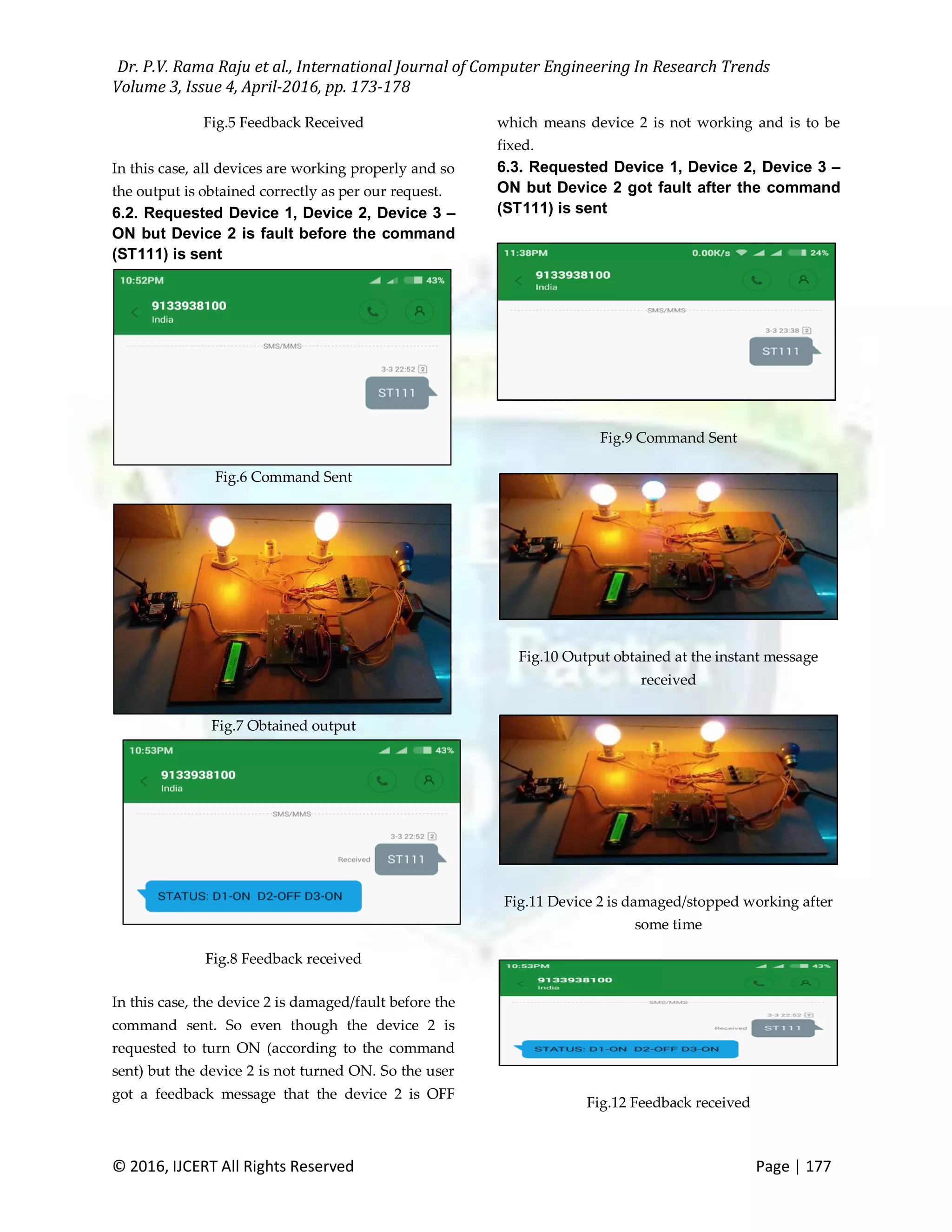

The document presents a project utilizing GSM technology for controlling and monitoring electrical devices remotely via SMS, allowing users to manage up to eight devices. It details the components used, including the AT89C52 microcontroller and GSM SIM900A modem, and explains the process of sending commands and receiving feedback regarding device status and faults. The system enhances user convenience compared to traditional remote controls by overcoming range limitations.