DTMF based home automation without using Microcontroller
This document describes a DTMF-based home automation system that allows controlling home appliances wirelessly using a mobile phone. It works by using a DTMF decoder chip to decode tones from the phone dial pad and trigger relays connected to devices. The system has advantages like wireless control and energy savings but limitations like limited number of controllable devices and lack of feedback. It finds applications in homes and industries for remote control of electrical systems.
DTMF based home automation without using Microcontroller
1.
Page 1 DTMF BASEDHOME AUTOMATION Sri Vasavi Institute Of Engineering and Technology (affiliated to JNTUK,Kakinada and Approved by AICTE,New Delhi) Nandamuru,Pedana Mandal, Krishna District, Andhra Pradesh 2015-2018 By S.L.PRASANTH
Page 3 INTRODUCTION Weuse many different types of communication in control applications to control home appliances, industrial appliances, and other type of automation. There are two types of communication that is we generally use - one is wired and other one is wireless. In wireless communication we transmits signal wirelessly, like using radio frequency (RF) and in wired communication in which we uses wires like copper wire. In this project “DTMF Based Home Automation System” we are going to control our home appliances wirelessly.
4.
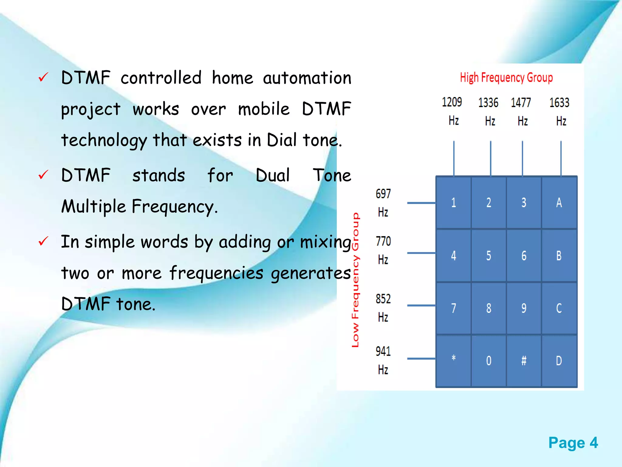
Page 4 DTMFcontrolled home automation project works over mobile DTMF technology that exists in Dial tone. DTMF stands for Dual Tone Multiple Frequency. In simple words by adding or mixing two or more frequencies generates DTMF tone.
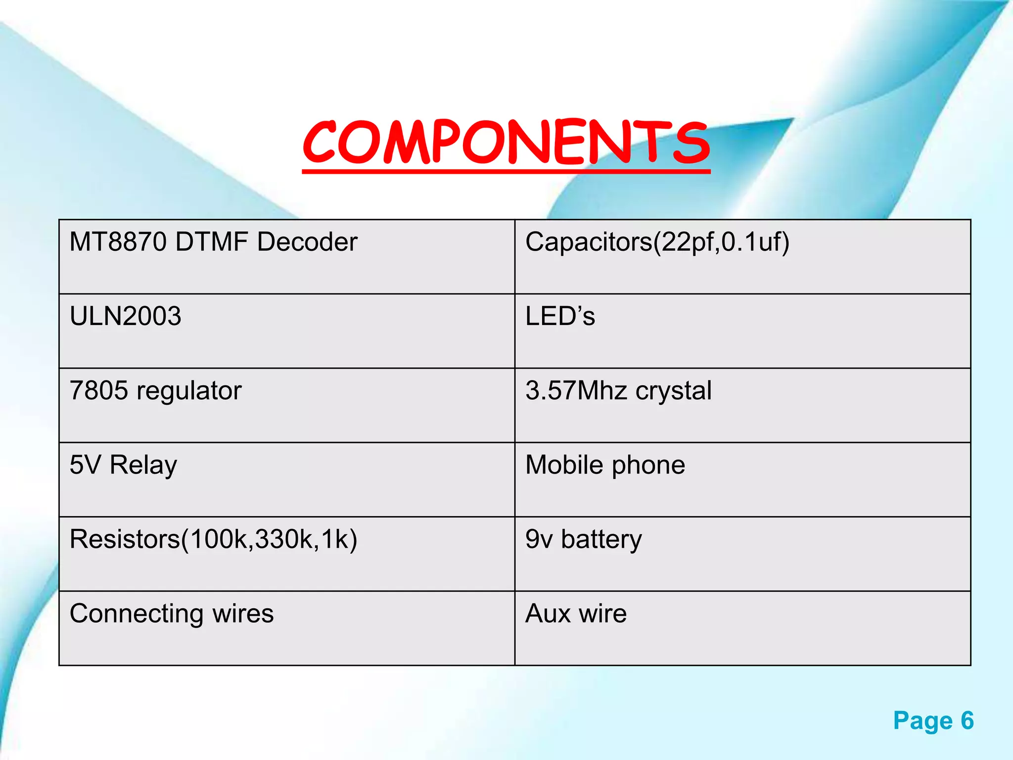
Page 7 MT8870 • TheMT8870D is a complete DTMF receiver integrating both the band split filter and digital decoder functions. The filter section uses switched capacitor techniques for high and low group filters; the decoder uses digital counting techniques to detect and decode all 16 DTMF tone-pairs into a 4-bit code.
8.
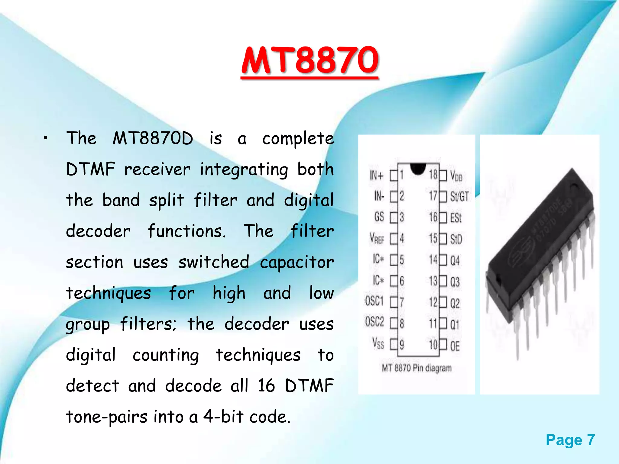
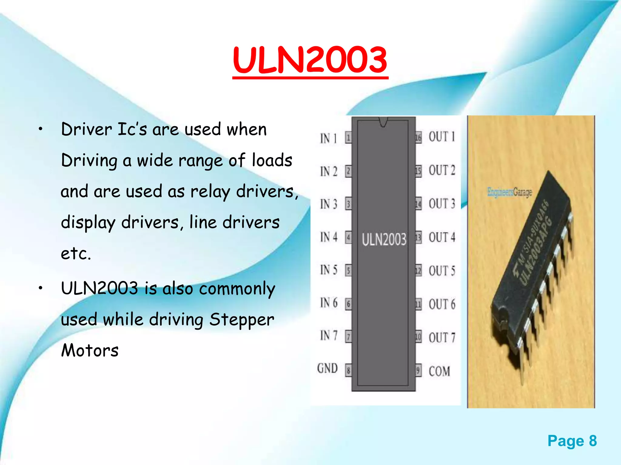
Page 8 ULN2003 • DriverIc’s are used when Driving a wide range of loads and are used as relay drivers, display drivers, line drivers etc. • ULN2003 is also commonly used while driving Stepper Motors
9.
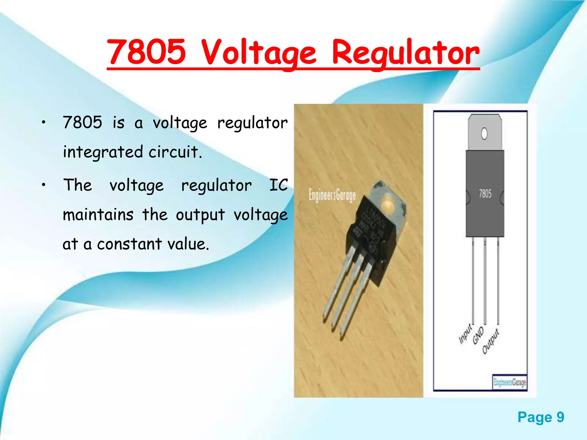
Page 9 7805 VoltageRegulator • 7805 is a voltage regulator integrated circuit. • The voltage regulator IC maintains the output voltage at a constant value.
10.
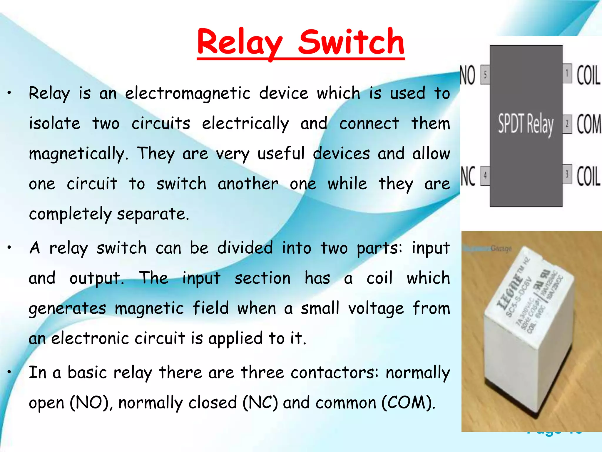
Page 10 Relay Switch •Relay is an electromagnetic device which is used to isolate two circuits electrically and connect them magnetically. They are very useful devices and allow one circuit to switch another one while they are completely separate. • A relay switch can be divided into two parts: input and output. The input section has a coil which generates magnetic field when a small voltage from an electronic circuit is applied to it. • In a basic relay there are three contactors: normally open (NO), normally closed (NC) and common (COM).
11.
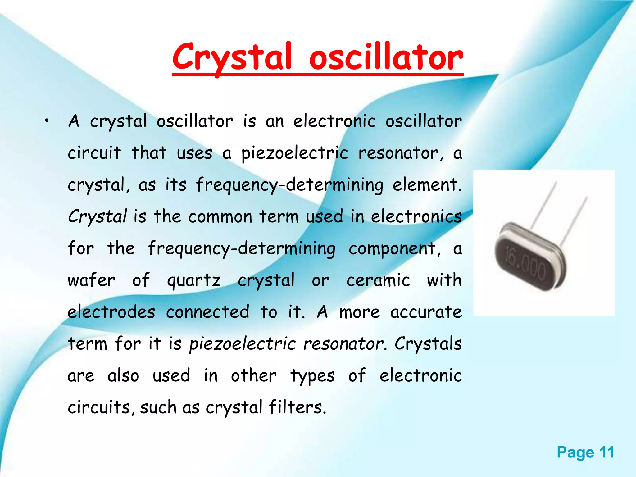
Page 11 Crystal oscillator •A crystal oscillator is an electronic oscillator circuit that uses a piezoelectric resonator, a crystal, as its frequency-determining element. Crystal is the common term used in electronics for the frequency-determining component, a wafer of quartz crystal or ceramic with electrodes connected to it. A more accurate term for it is piezoelectric resonator. Crystals are also used in other types of electronic circuits, such as crystal filters.
12.
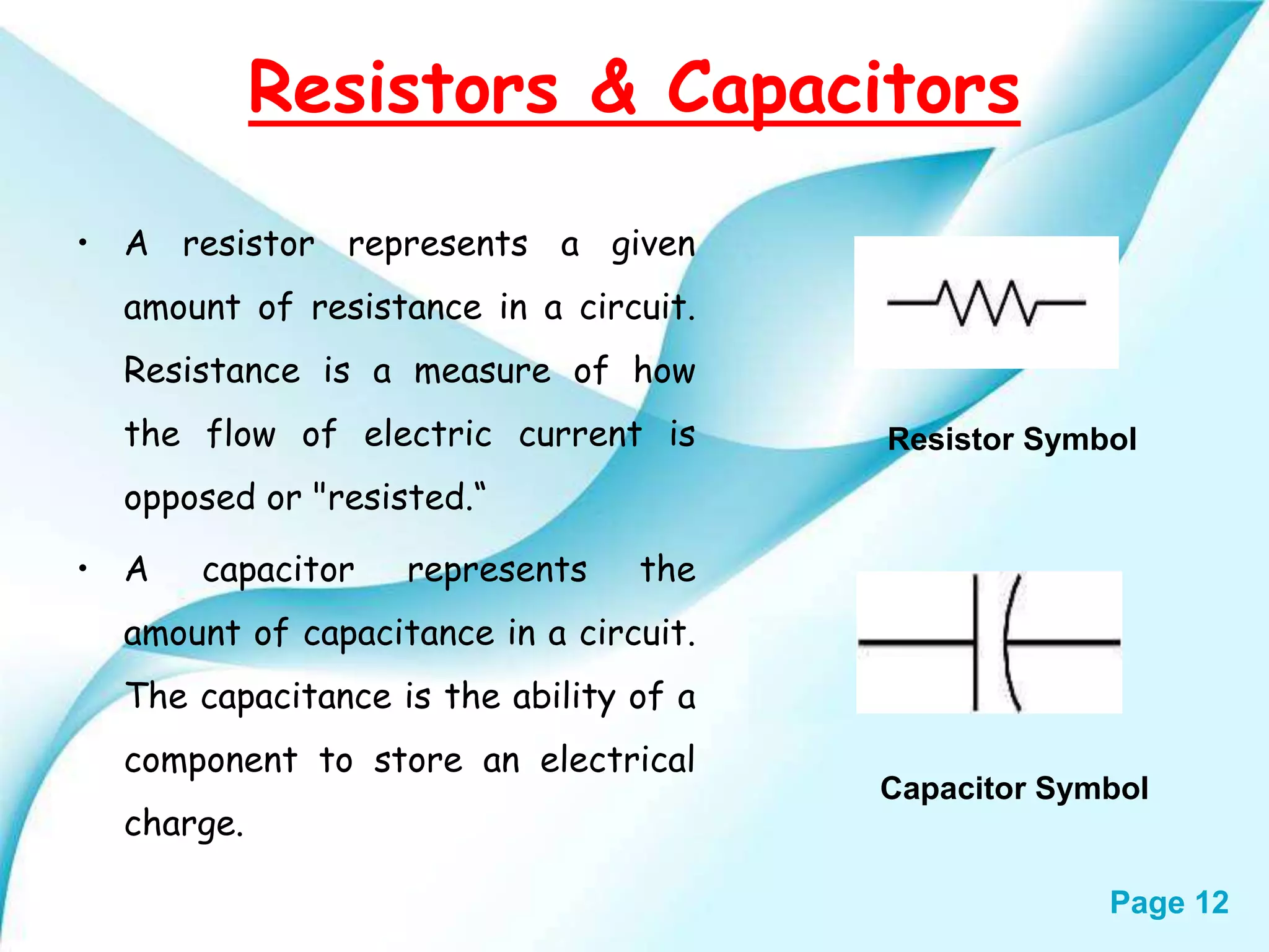
Page 12 Resistors &Capacitors • A resistor represents a given amount of resistance in a circuit. Resistance is a measure of how the flow of electric current is opposed or "resisted.“ • A capacitor represents the amount of capacitance in a circuit. The capacitance is the ability of a component to store an electrical charge. Capacitor Symbol Resistor Symbol
13.
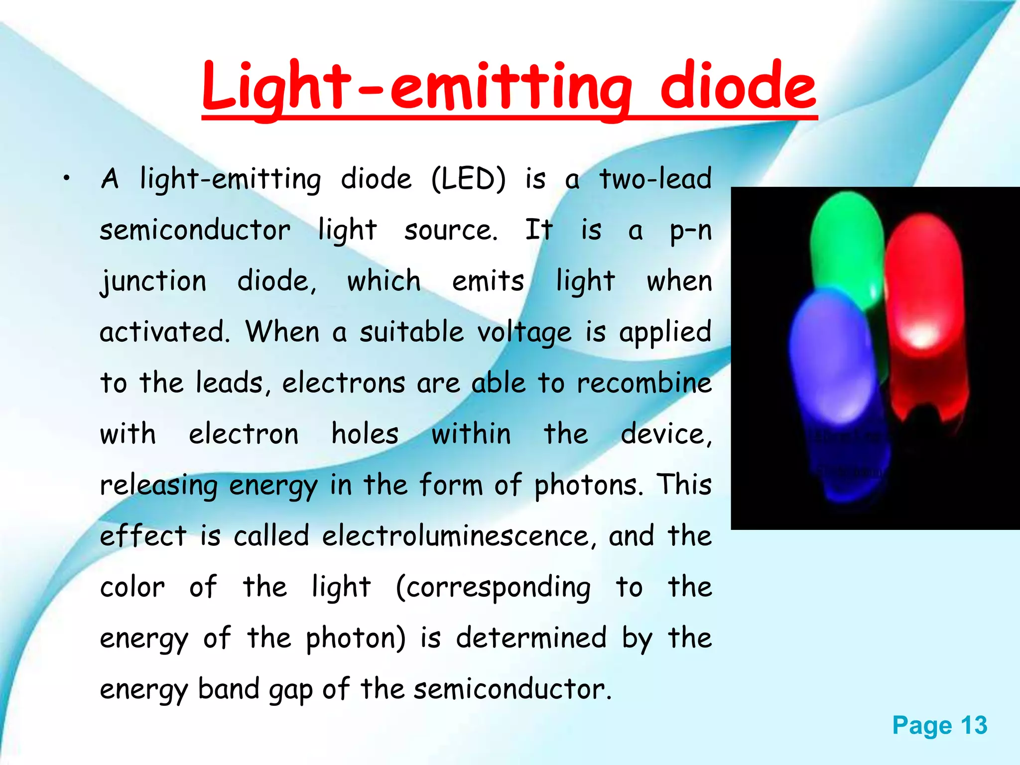
Page 13 Light-emitting diode •A light-emitting diode (LED) is a two-lead semiconductor light source. It is a p–n junction diode, which emits light when activated. When a suitable voltage is applied to the leads, electrons are able to recombine with electron holes within the device, releasing energy in the form of photons. This effect is called electroluminescence, and the color of the light (corresponding to the energy of the photon) is determined by the energy band gap of the semiconductor.
14.
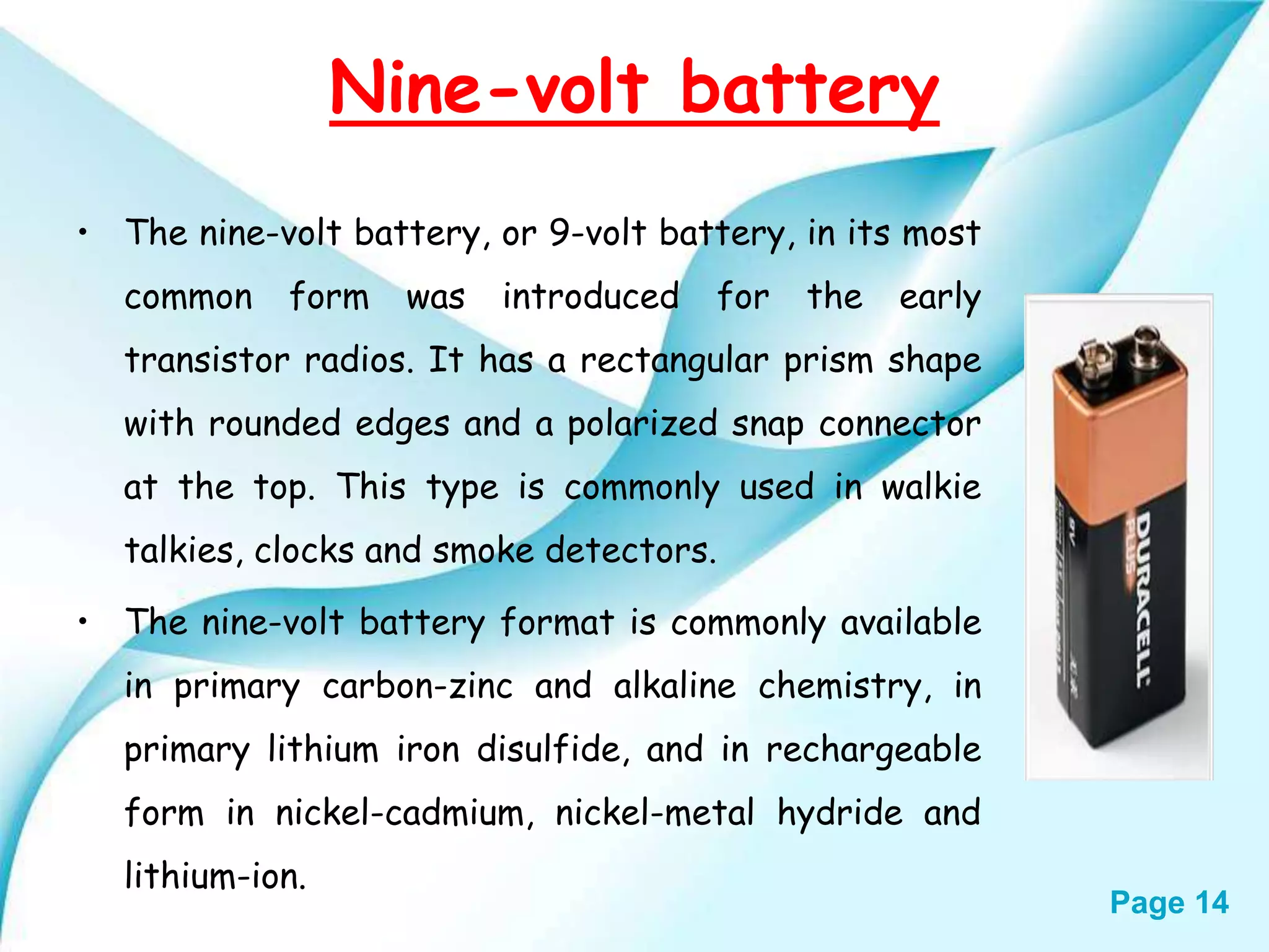
Page 14 Nine-volt battery •The nine-volt battery, or 9-volt battery, in its most common form was introduced for the early transistor radios. It has a rectangular prism shape with rounded edges and a polarized snap connector at the top. This type is commonly used in walkie talkies, clocks and smoke detectors. • The nine-volt battery format is commonly available in primary carbon-zinc and alkaline chemistry, in primary lithium iron disulfide, and in rechargeable form in nickel-cadmium, nickel-metal hydride and lithium-ion.
15.
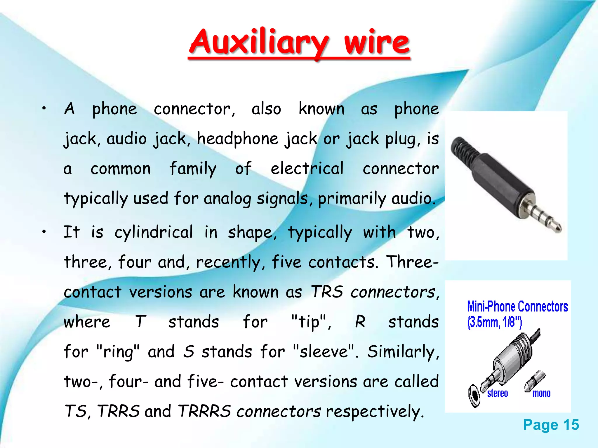
Page 15 Auxiliary wire •A phone connector, also known as phone jack, audio jack, headphone jack or jack plug, is a common family of electrical connector typically used for analog signals, primarily audio. • It is cylindrical in shape, typically with two, three, four and, recently, five contacts. Three- contact versions are known as TRS connectors, where T stands for "tip", R stands for "ring" and S stands for "sleeve". Similarly, two-, four- and five- contact versions are called TS, TRRS and TRRRS connectors respectively.
16.
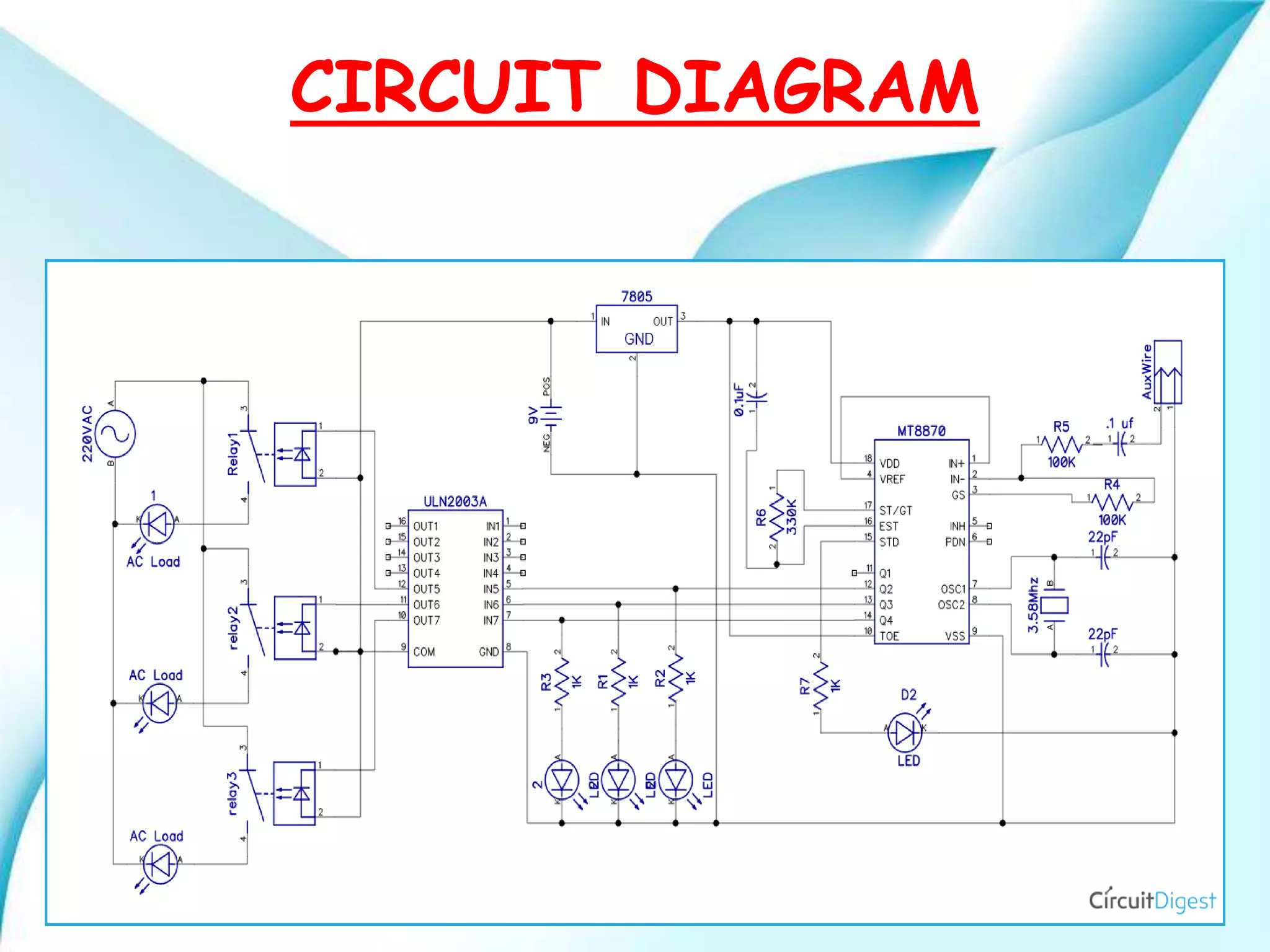
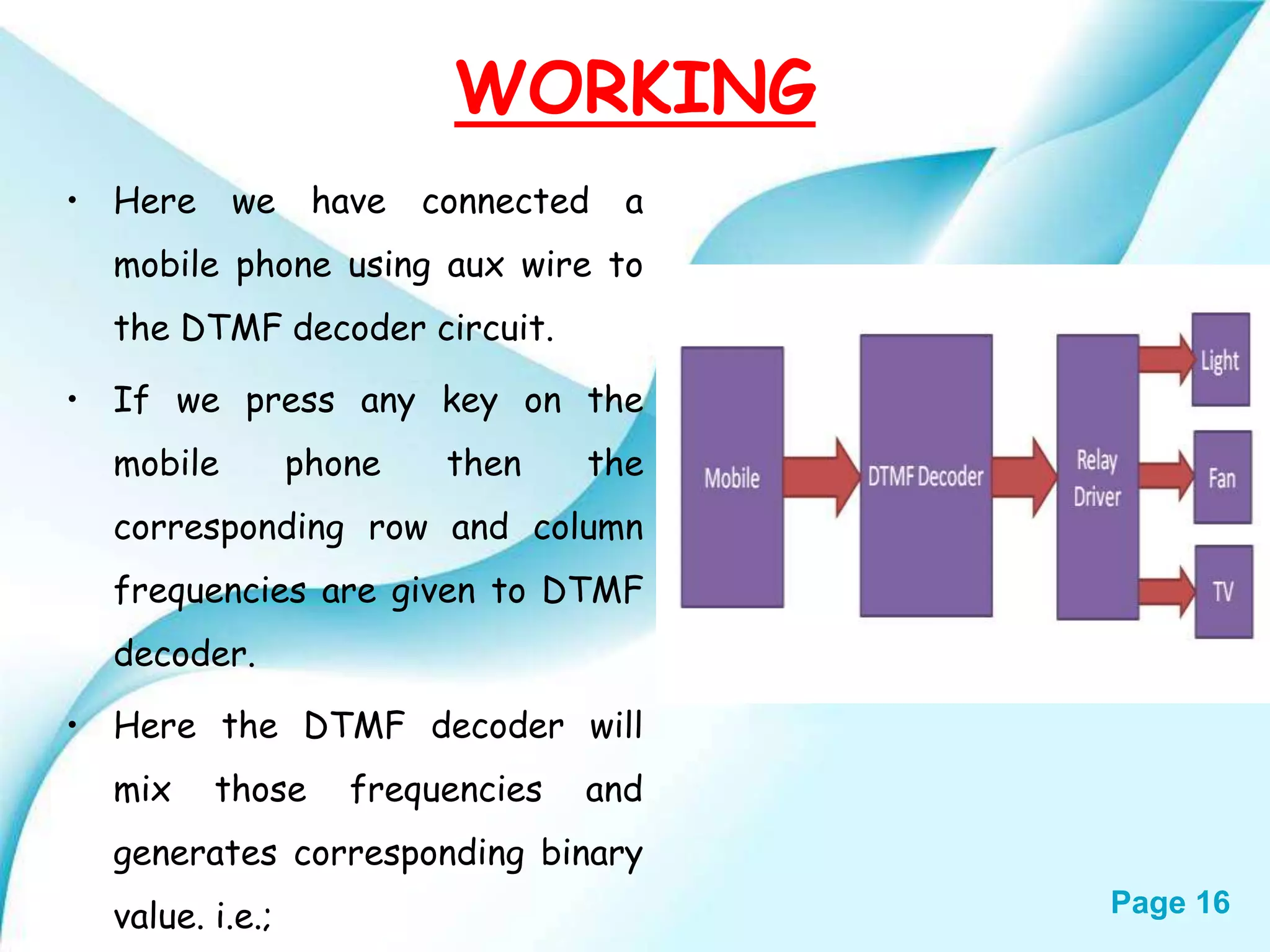
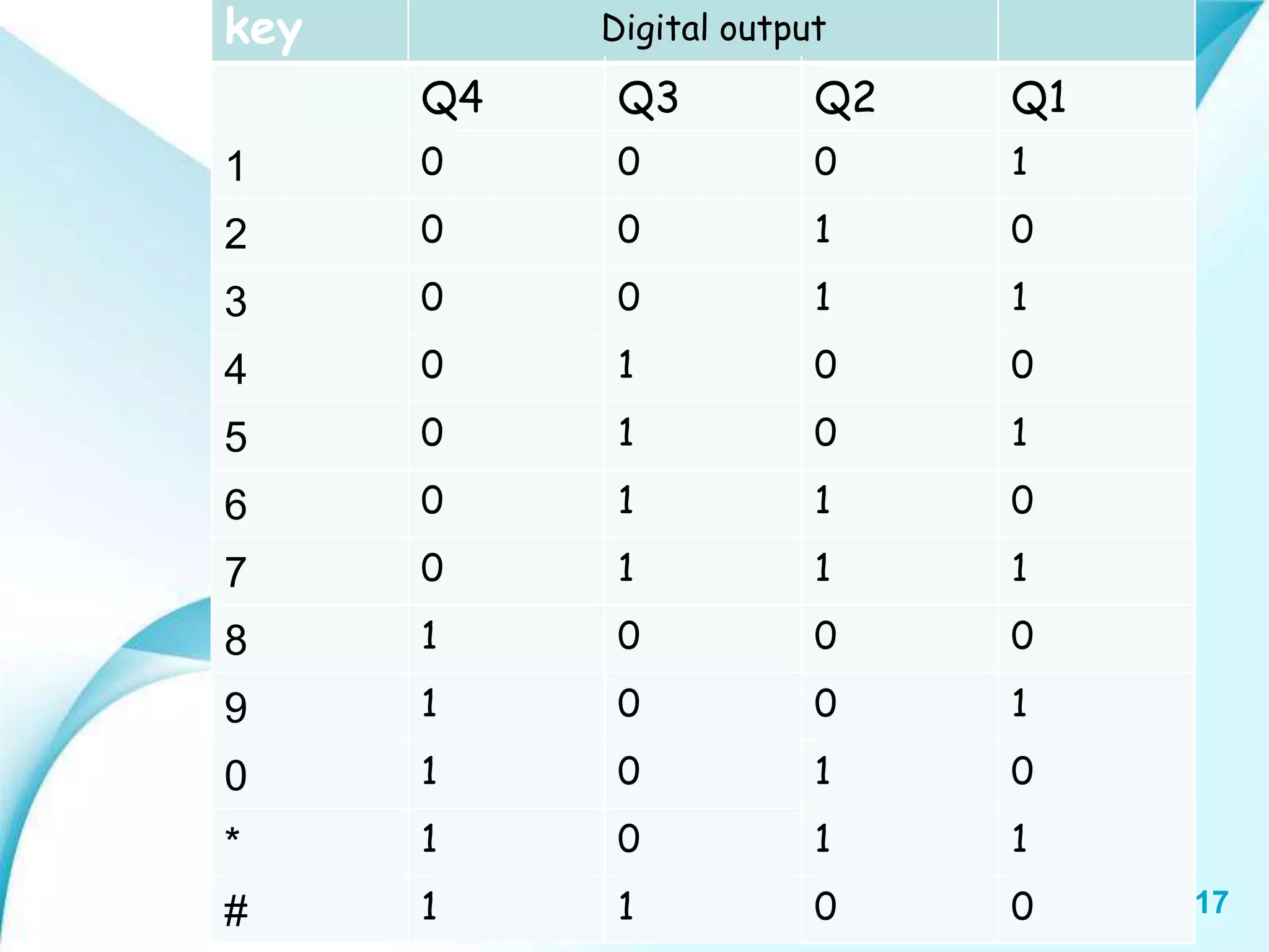
Page 16 WORKING • Herewe have connected a mobile phone using aux wire to the DTMF decoder circuit. • If we press any key on the mobile phone then the corresponding row and column frequencies are given to DTMF decoder. • Here the DTMF decoder will mix those frequencies and generates corresponding binary value. i.e.;
Page 18 TheDTMF decoder output is connected to driver IC. Here the driver IC is used to drive the relays for supplying the constant voltage. Here the relays are connected to the driver IC. Relay is ON when the decoder output is HIGH otherwise the relay is OFF state. The outputs of relays are Q1,Q2,Q3,Q4 and they are connected to different electronic appliances like AC,FAN,MOTOR,....... etc; If Q1 is 1(i.e.; HIGH) then the corresponding device is ON. If it is 0(i.e.; LOW) that device is OFF. WORKING
19.
Page 19 ADVANTAGES Easyto maintain and repair. Comparatively the operation cost is less. Design is efficient and low cost. Power consumption is low. Controlling electrical devices wirelessly Saves electricity (when we forget to switch off and go out). We can control appliances from any place round the globe. No coding is required.
20.
Page 20 DIS ADVANTAGES This system is not capable of displaying the feedback status of the devices being operated. This system needs a cell phone to be placed in circuit. Anyone who knows the phone number and can control our electrical appliances Number of electrical appliances that can be controlled by this circuit is limited.
21.
Page 21 APPLICATIONS Thissystem can be used in industrial applications. This system can be employed in houses, where people often forget to switch off electrical appliances. This system can be used to control AC’s to set the room temperature when we are outside. We can extend this circuit to control many electrical devices with some modifications using 4 x16 decoder IC.
22.
Page 22 CONCLUSION • Inthese by making these the circuit as the device is connected to a corresponding circuit, its gets activated as soon as the call is made to the circuit in which mobile or equivalent GSM module is present to perform a specific operation as per the relay device is connected. • In these as the keypad has12 different key, it can perform 12 distinct operation as per connected to a relay.