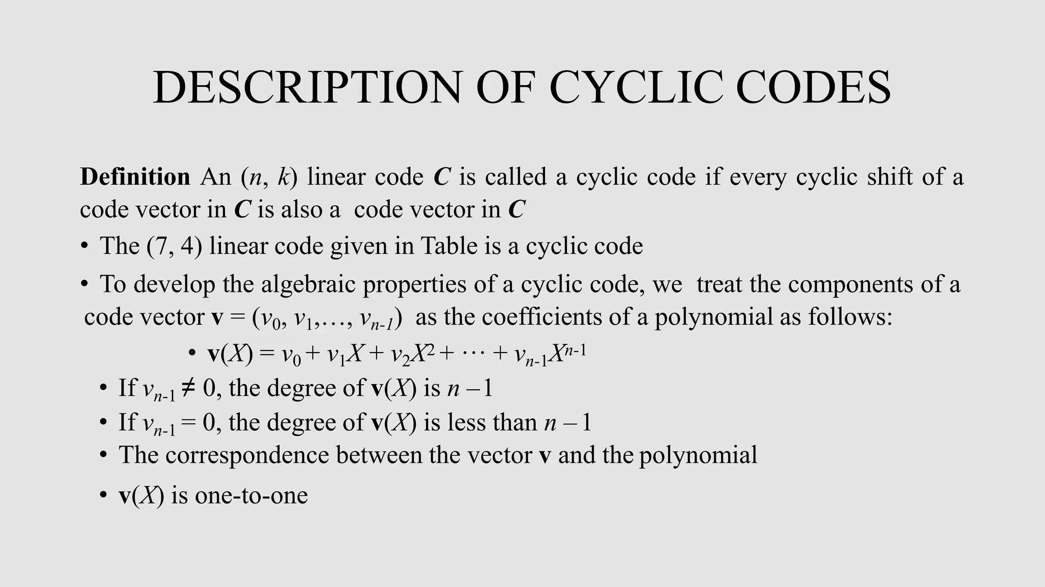
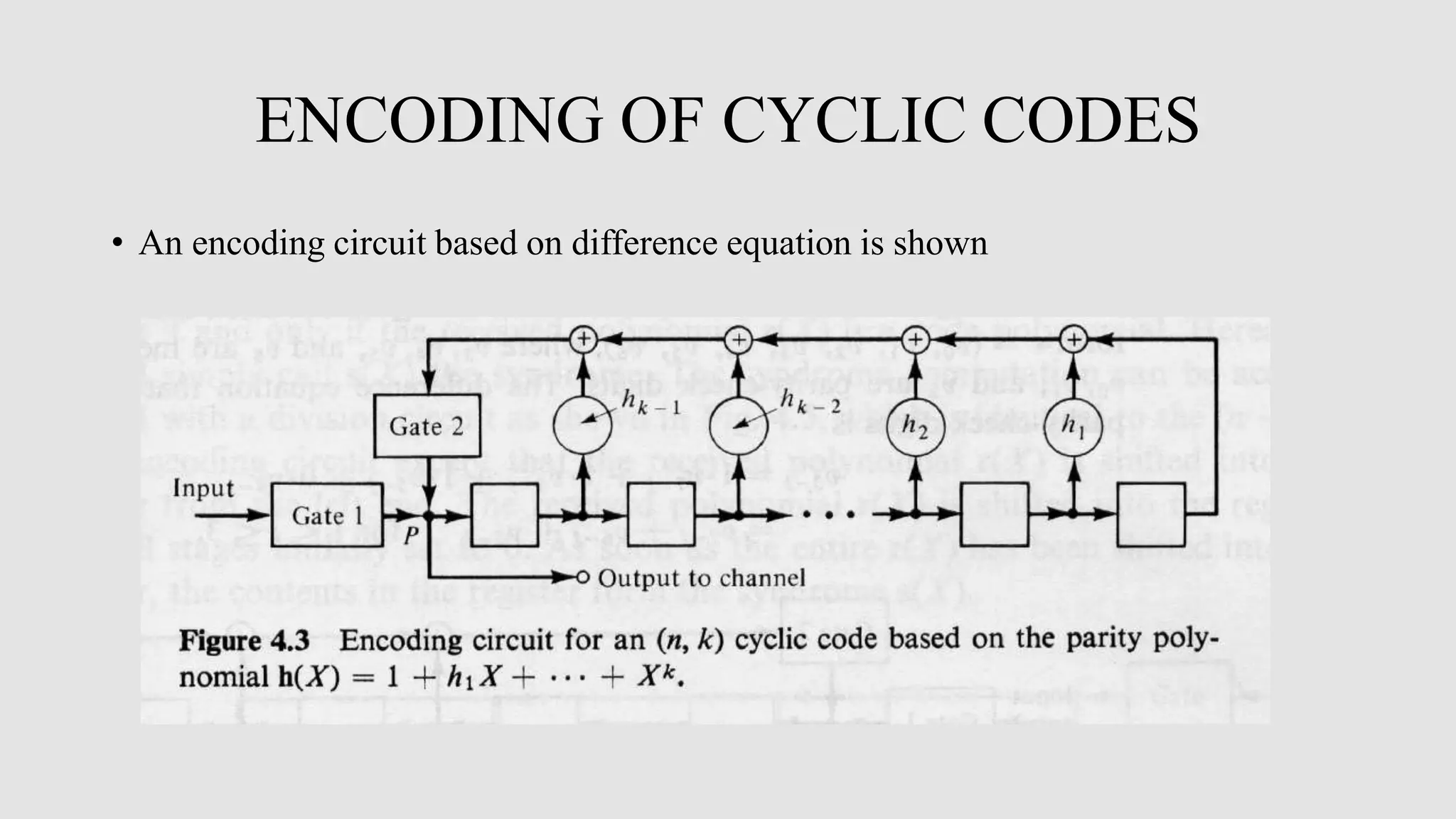
Cyclic codes are a type of linear code where any cyclic shift of a codeword is also a codeword. This allows for efficient encoding and decoding using shift registers. Encoding of cyclic codes can be done by dividing the message polynomial by the generator polynomial, with the remainder becoming the parity bits. Encoding circuits use shift registers with feedback to efficiently perform this division. Decoding uses the syndrome, which is computed by shifting the received word into a syndrome register. A decoder then attempts to match the syndrome to an error pattern, correcting errors one symbol at a time by shifting the syndrome and received word simultaneously.


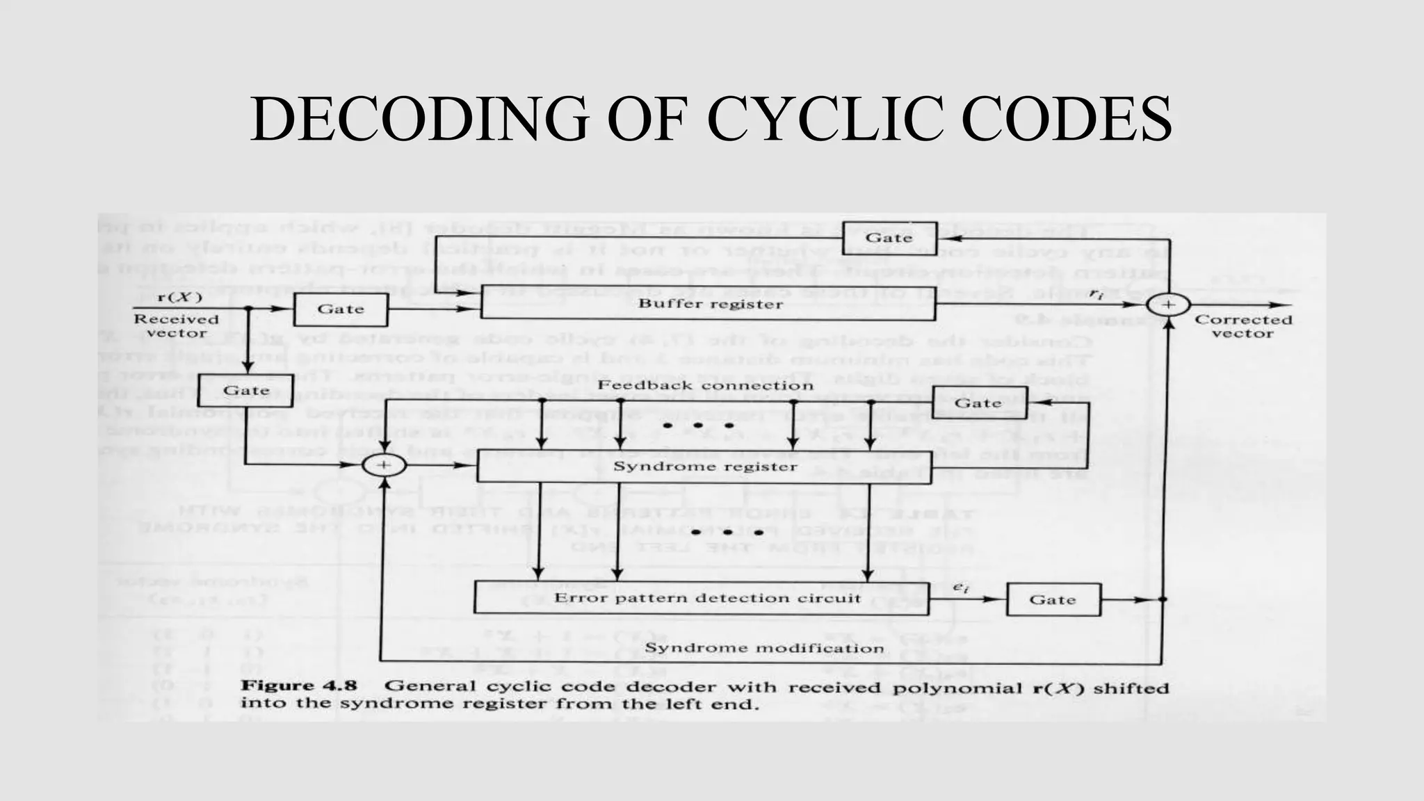
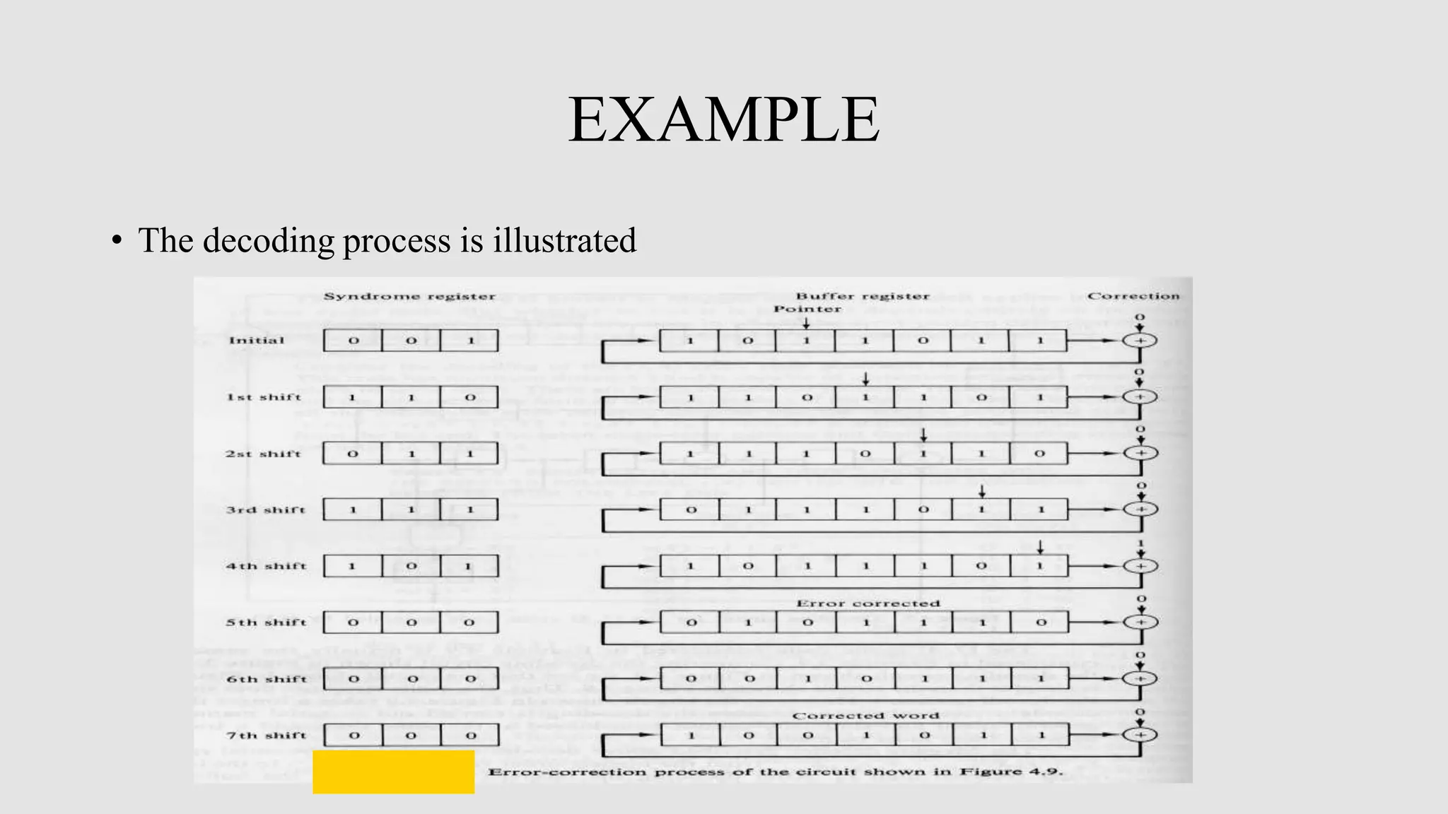
![DECODING OF CYCLIC CODES The syndrome s1 (1)(X) of r1 (1)(X) is the remainder resulting from dividing X[s(X)+Xn-1] by the generator polynomial g(X). Since the remainders resulting from dividing Xs(X) and Xn by g(X) are s(1)(X) and 1, respectively, we have s1 (1)(X)= s(1)(X)+1. Therefore, if 1 is added to the left end of the syndrome register while it is shifted, we obtain s1 (1)(X). • A general decoder for an (n, k) cyclic code is shown in Fig. 5.8 It consists of three major parts • A syndrome register • An error-pattern detector • A buffer register to hold the received vector](https://image.slidesharecdn.com/dcomala-210510130318/75/DIGITAL-COMMUNICATION-ENCODING-AND-DECODING-OF-CYCLIC-CODE-24-2048.jpg)