#2 A taxonomy first introduced by Flynn [FLYN72] is still the most common way of categorizing systems with parallel processing capability. Flynn proposed the following categories of computer systems: Single instruction, single data (SISD) stream: A single processor executes a single instruction stream to operate on data stored in a single memory. Uniprocessors fall into this category. Single instruction, multiple data (SIMD) stream: A single machine instruction controls the simultaneous execution of a number of processing elements on a lockstep basis. Each processing element has an associated data memory, so that instructions are executed on different sets of data by different processors. Vector and array processors fall into this category, and are discussed in Section 18.7. Multiple instruction, single data (MISD) stream: A sequence of data is transmitted to a set of processors, each of which executes a different instruction sequence. This structure is not commercially implemented. Multiple instruction, multiple data (MIMD) stream: A set of processors simultaneously execute different instruction sequences on different data sets. SMPs, clusters, and NUMA systems fit into this category.
#3 With the MIMD organization, the processors are general purpose; each is able to process all of the instructions necessary to perform the appropriate data transformation. MIMDs can be further subdivided by the means in which the processors communicate (Figure 20.1). If the processors share a common memory, then each processor accesses programs and data stored in the shared memory, and processors communicate with each other via that memory. The most common form of such system is known as a symmetric multiprocessor (SMP), which we examine in Section 20.2. In an SMP, multiple processors share a single memory or pool of memory by means of a shared bus or other interconnection mechanism; a distinguishing feature is that the memory access time to any region of memory is approximately the same for each processor. A more recent development is the non-uniform memory access (NUMA) organization, which is described in Section 20.6. As the name suggests, the memory access time to different regions of memory may differ for a NUMA processor. A collection of independent uniprocessors or SMPs may be interconnected to form a cluster. Communication among the computers is either via fixed paths or via some network facility.
#4 Figure 20.2 illustrates the general organization of the taxonomy of Figure 20.1. Figure 20.2a shows the structure of an SISD. There is some sort of control unit (CU) that provides an instruction stream (IS) to a processing unit (PU). The processing unit operates on a single data stream (DS) from a memory unit (MU). With an SIMD, there is still a single control unit, now feeding a single instruction stream to multiple PUs. Each PU may have its own dedicated memory (illustrated in Figure 20.2b), or there may be a shared memory. Finally, with the MIMD, there are multiple control units, each feeding a separate instruction stream to its own PU. The MIMD may be a shared-memory multiprocessor (Figure 20.2c) or a distributed- memory multicomputer (Figure 20.2d). The design issues relating to SMPs, clusters, and NUMAs are complex, involving issues relating to physical organization, interconnection structures, inter-processor communication, operating system design, and application software techniques. Our concern here is primarily with organization, although we touch briefly on operating system design issues.
#5 Until fairly recently, virtually all single-user personal computers and most workstations contained a single general-purpose microprocessor. As demands for performance increase and as the cost of microprocessors continues to drop, vendors have introduced systems with an SMP organization. The term SMP refers to a computer hardware architecture and also to the operating system behavior that reflects that architecture. An SMP can be defined as a standalone computer system with the following characteristics: 1. There are two or more similar processors of comparable capability. 2. These processors share the same main memory and I/O facilities and are interconnected by a bus or other internal connection scheme, such that memory access time is approximately the same for each processor. 3. All processors share access to I/O devices, either through the same channels or through different channels that provide paths to the same device. 4. All processors can perform the same functions (hence the term symmetric). 5. The system is controlled by an integrated operating system that provides interaction between processors and their programs at the job, task, file, and data element levels. Points 1 to 4 should be self-explanatory. Point 5 illustrates one of the contrasts with a loosely coupled multiprocessing system, such as a cluster. In the latter, the physical unit of interaction is usually a message or complete file. In an SMP, individual data elements can constitute the level of interaction, and there can be a high degree of cooperation between processes.
#6 The operating system of an SMP schedules processes or threads across all of the processors. An SMP organization has a number of potential advantages over a uniprocessor organization, including the following: • Performance: If the work to be done by a computer can be organized so that some portions of the work can be done in parallel, then a system with multiple processors will yield greater performance than one with a single processor of the same type (Figure 20.3). * Availability: In a symmetric multiprocessor, because all processors can perform the same functions, the failure of a single processor does not halt the machine. Instead, the system can continue to function at reduced performance. * Incremental growth: A user can enhance the performance of a system by adding an additional processor. * Scaling: Vendors can offer a range of products with different price and performance characteristics based on the number of processors configured in the system. It is important to note that these are potential, rather than guaranteed, benefits. The operating system must provide tools and functions to exploit the parallelism in an SMP system. An attractive feature of an SMP is that the existence of multiple processors is transparent to the user. The operating system takes care of scheduling of threads or processes on individual processors and of synchronization among processors.
#7 Figure 20.4 depicts in general terms the organization of a multiprocessor system. There are two or more processors. Each processor is self-contained, including a control unit, ALU, registers, and, typically, one or more levels of cache. Each processor has access to a shared main memory and the I/O devices through some form of interconnection mechanism. The processors can communicate with each other through memory (messages and status information left in common data areas). It may also be possible for processors to exchange signals directly. The memory is often organized so that multiple simultaneous accesses to separate blocks of memory are possible. In some configurations, each processor may also have its own private main memory and I/O channels in addition to the shared resources.
#8 The most common organization for personal computers, workstations, and servers is the time-shared bus. The time-shared bus is the simplest mechanism for constructing a multiprocessor system (Figure 20.5). The structure and interfaces are basically the same as for a single-processor system that uses a bus interconnection. The bus consists of control, address, and data lines. To facilitate DMA transfers from I/O subsystems to processors, the following features are provided: Addressing: It must be possible to distinguish modules on the bus to determine the source and destination of data. Arbitration: Any I/O module can temporarily function as “master.” A mechanism is provided to arbitrate competing requests for bus control, using some sort of priority scheme. Time-sharing: When one module is controlling the bus, other modules are locked out and must, if necessary, suspend operation until bus access is achieved. These uniprocessor features are directly usable in an SMP organization. In this latter case, there are now multiple processors as well as multiple I/O processors all attempting to gain access to one or more memory modules via the bus.
#9 The bus organization has several attractive features: • Simplicity: This is the simplest approach to multiprocessor organization. The physical interface and the addressing, arbitration, and time-sharing logic of each processor remain the same as in a single-processor system. • Flexibility: It is generally easy to expand the system by attaching more processors to the bus. • Reliability: The bus is essentially a passive medium, and the failure of any attached device should not cause failure of the whole system.
#10 The main drawback to the bus organization is performance. All memory references pass through the common bus. Thus, the bus cycle time limits the speed of the system. To improve performance, it is desirable to equip each processor with a cache memory. This should reduce the number of bus accesses dramatically. Typically, workstation and PC SMPs have two levels of cache, with the L1 cache internal (same chip as the processor) and the L2 cache either internal or external. Some processors now employ a L3 cache as well. The use of caches introduces some new design considerations. Because each local cache contains an image of a portion of memory, if a word is altered in one cache, it could conceivably invalidate a word in another cache. To prevent this, the other processors must be alerted that an update has taken place. This problem is known as the cache coherence problem and is typically addressed in hardware rather than by the operating system.
#11 An SMP operating system manages processor and other computer resources so that the user perceives a single operating system controlling system resources. In fact, such a configuration should appear as a single-processor multiprogramming system. In both the SMP and uniprocessor cases, multiple jobs or processes may be active at one time, and it is the responsibility of the operating system to schedule their execution and to allocate resources. A user may construct applications that use multiple processes or multiple threads within processes without regard to whether a single processor or multiple processors will be available. Thus, a multiprocessor operating system must provide all the functionality of a multiprogramming system plus additional features to accommodate multiple processors. Among the key design issues: Simultaneous concurrent processes: OS routines need to be reentrant to allow several processors to execute the same IS code simultaneously. With multiple processors executing the same or different parts of the OS, OS tables and management structures must be managed properly to avoid deadlock or invalid operations. Scheduling: Any processor may perform scheduling, so conflicts must be avoided. The scheduler must assign ready processes to available processors. Synchronization: With multiple active processes having potential access to shared address spaces or shared I/O resources, care must be taken to provide effective synchronization. Synchronization is a facility that enforces mutual exclusion and event ordering. Memory management: Memory management on a multiprocessor must deal with all of the issues found on uniprocessor machines, as is discussed in Chapter 9. In addition, the operating system needs to exploit the available hardware parallelism, such as multi-ported memories, to achieve the best performance. The paging mechanisms on different processors must be coordinated to enforce consistency when several processors share a page or segment and to decide on page replacement. Reliability and fault tolerance: The operating system should provide graceful degradation in the face of processor failure. The scheduler and other portions of the operating system must recognize the loss of a processor and restructure management tables accordingly.
#12 Software cache coherence schemes attempt to avoid the need for additional hard- ware circuitry and logic by relying on the compiler and operating system to deal with the problem. Software approaches are attractive because the overhead of detecting potential problems is transferred from run time to compile time, and the design complexity is transferred from hardware to software. On the other hand, compile- time software approaches generally must make conservative decisions, leading to inefficient cache utilization. Compiler-based coherence mechanisms perform an analysis on the code to determine which data items may become unsafe for caching, and they mark those items accordingly. The operating system or hardware then prevents non-cacheable items from being cached. The simplest approach is to prevent any shared data variables from being cached. This is too conservative, because a shared data structure may be exclusively used during some periods and may be effectively read-only during other periods. It is only during periods when at least one process may update the variable and at least one other process may access the variable that cache coherence is an issue. More efficient approaches analyze the code to determine safe periods for shared variables. The compiler then inserts instructions into the generated code to enforce cache coherence during the critical periods. A number of techniques have been developed for performing the analysis and for enforcing the results; see [LILJ93] and [STEN90] for surveys.
#13 Hardware-based solutions are generally referred to as cache coherence protocols. These solutions provide dynamic recognition at run time of potential inconsistency conditions. Because the problem is only dealt with when it actually arises, there is more effective use of caches, leading to improved performance over a software approach. In addition, these approaches are transparent to the programmer and the compiler, reducing the software development burden. Hardware schemes differ in a number of particulars, including where the state information about data lines is held, how that information is organized, where coherence is enforced, and the enforcement mechanisms. In general, hardware schemes can be divided into two categories: directory protocols and snoopy protocols.
#14 Directory protocols collect and maintain information about where copies of lines reside. Typically, there is a centralized controller that is part of the main memory controller, and a directory that is stored in main memory. The directory contains global state information about the contents of the various local caches. When an individual cache controller makes a request, the centralized controller checks and issues necessary commands for data transfer between memory and caches or between caches. It is also responsible for keeping the state information up to date; therefore, every local action that can affect the global state of a line must be reported to the central controller. Typically, the controller maintains information about which processors have a copy of which lines. Before a processor can write to a local copy of a line, it must request exclusive access to the line from the controller. Before granting this exclusive access, the controller sends a message to all processors with a cached copy of this line, forcing each processor to invalidate its copy. After receiving acknowledgments back from each such processor, the controller grants exclusive access to the requesting processor. When another processor tries to read a line that is exclusively granted to another processor, it will send a miss notification to the controller. The controller then issues a command to the processor holding that line that requires the processor to do a write back to main memory. The line may now be shared for reading by the original processor and the requesting processor. Directory schemes suffer from the drawbacks of a central bottleneck and the overhead of communication between the various cache controllers and the central controller. However, they are effective in large-scale systems that involve multiple buses or some other complex interconnection scheme.
#15 Snoopy protocols distribute the responsibility for maintaining cache coherence among all of the cache controllers in a multiprocessor. A cache must recognize when a line that it holds is shared with other caches. When an update action is performed on a shared cache line, it must be announced to all other caches by a broadcast mechanism. Each cache controller is able to “snoop” on the network to observe these broadcasted notifications, and react accordingly. Snoopy protocols are ideally suited to a bus-based multiprocessor, because the shared bus provides a simple means for broadcasting and snooping. However, because one of the objectives of the use of local caches is to avoid bus accesses, care must be taken that the increased bus traffic required for broadcasting and snooping does not cancel out the gains from the use of local caches. Two basic approaches to the snoopy protocol have been explored: write invalidate and write update (or write broadcast).
#16 With a write-invalidate protocol, there can be multiple readers but only one writer at a time. Initially, a line may be shared among several caches for reading purposes. When one of the caches wants to per- form a write to the line, it first issues a notice that invalidates that line in the other caches, making the line exclusive to the writing cache. Once the line is exclusive, the owning processor can make cheap local writes until some other processor requires the same line. The write-invalidate approach is the most widely used in commercial multi- processor systems, such as the x86 architecture. It marks the state of every cache line (using two extra bits in the cache tag) as modified, exclusive, shared, or invalid. For this reason, the write-invalidate protocol is called MESI. In the remainder of this section, we will look at its use among local caches across a multiprocessor. For simplicity in the presentation, we do not examine the mechanisms involved in coordinating among both level 1 and level 2 locally as well as at the same time coordinating across the distributed multiprocessor. This would not add any new principles but would greatly complicate the discussion.
#17 With a write-update protocol, there can be multiple writers as well as multiple readers. When a processor wishes to update a shared line, the word to be updated is distributed to all others, and caches containing that line can update it. Neither of these two approaches is superior to the other under all circum- stances. Performance depends on the number of local caches and the pattern of memory reads and writes. Some systems implement adaptive protocols that employ both write-invalidate and write-update mechanisms.
#18 To provide cache consistency on an SMP, the data cache often supports a protocol known as MESI. For MESI, the data cache includes two status bits per tag, so that each line can be in one of four states: • Modified: The line in the cache has been modified (different from main memory) and is available only in this cache. • Exclusive: The line in the cache is the same as that in main memory and is not present in any other cache. • Shared: The line in the cache is the same as that in main memory and may be present in another cache. • Invalid: The line in the cache does not contain valid data.
#19 Table 20.1 summarizes the meaning of the four states.
#20 Figure 20.6 displays a state diagram for the MESI protocol. Keep in mind that each line of the cache has its own state bits and therefore its own realization of the state diagram. Figure 20.6a shows the transitions that occur due to actions initiated by the processor attached to this cache. Figure 20.6b shows the transitions that occur due to events that are snooped on the common bus. This presentation of separate state diagrams for processor-initiated and bus-initiated actions helps to clarify the logic of the MESI protocol. At any time a cache line is in a single state. If the next event is from the attached processor, then the transition is dictated by Figure 20.6a and if the next event is from the bus, the transition is dictated by Figure 20.6b.
#21 Figure 20.7 summarizes the state relationship between lines in different caches, all of which map to the same block of memory.
#22 When a read miss occurs in the local cache, the processor initiates a memory read to read the line of main memory containing the missing address. The processor inserts a signal on the bus that alerts all other processor/cache units to snoop the transaction. There are a number of possible outcomes: ■ If one other cache has a clean (unmodified since read from memory) copy of the line in the exclusive state, it returns a signal indicating that it shares this line. The responding processor then transitions the state of its copy from exclusive to shared, and the initiating processor reads the line from main memory and transitions the line in its cache from invalid to shared. ■ If one or more caches have a clean copy of the line in the shared state, each of them signals that it shares the line. The initiating processor reads the line and transitions the line in its cache from invalid to shared. ■ If one other cache has a modified copy of the line, then that cache blocks the memory read and provides the line to the requesting cache over the shared bus. The responding cache then changes its line from modified to shared.1 The line sent to the requesting cache is also received and processed by the memory controller, which stores the block in memory. ■ If no other cache has a copy of the line (clean or modified), then no signals are returned. The initiating processor reads the line and transitions the line in its cache from invalid to exclusive.
#23 When a read hit occurs on a line currently in the local cache, the processor simply reads the required item. There is no state change: The state remains modified, shared, or exclusive.
#24 When a write miss occurs in the local cache, the processor initiates a memory read to read the line of main memory containing the missing address. For this purpose, the processor issues a signal on the bus that means read-with-intent-to-modify (RWITM). When the line is loaded, it is immediately marked modified. With respect to other caches, two possible scenarios precede the loading of the line of data. First, some other cache may have a modified copy of this line (state = modify). In this case, the alerted processor signals the initiating processor that another processor has a modified copy of the line. The initiating processor surrenders the bus and waits. The other processor gains access to the bus, writes the modified cache line back to main memory, and transitions the state of the cache line to invalid (because the initiating processor is going to modify this line). Subsequently, the initiating processor will again issue a signal to the bus of RWITM and then read the line from main memory, modify the line in the cache, and mark the line in the modified state. The second scenario is that no other cache has a modified copy of the requested line. In this case, no signal is returned, and the initiating processor proceeds to read in the line and modify it. Meanwhile, if one or more caches have a clean copy of the line in the shared state, each cache invalidates its copy of the line, and if one cache has a clean copy of the line in the exclusive state, it invalidates its copy of the line.
#26 It will help to clarify the state transition diagrams of Figure 20.6 to develop flowcharts that show the exchange of signals between cooperating caches during a read or write operation. The following flowcharts assume an initiator system and one or more other participants, and refer to the state of a cache line in each system that all map to the same block of main memory. Figure 20.8 covers the case of a memory read operation. If the desired word is contained in a cache line of the initiator’s cache, then the line must be in the M, E, or S state. In that case, the word is retrieved from the cache and returned to the processor. If the cache line is not present, then the initiator signals a read miss (RM) to the other participants. This indicates that it is going to perform a read memory operation to bring in the memory block containing the desired word after waiting for responding signals. Then, if necessary the initiator writes back a line of cache to make room for the incoming block. At the participant end, the participant checks to see if the requested block is in a line of its cache. If not, it signals back null and is done. If the participant has the desired line in either the E or S state, it signals S, because now the line will be shared with the initiator, and sets the line state to S. If the line is in the M state, it signals M to the initiator. Then the participant writes back the line to bring main memory up to date and move to an S state. If the initiator receives a signal M, it waits until the participant has written the line back to memory before proceeding. If the signal is M or S, the initiator sets the line to S and if the incoming signal is null it sets the state to E. Once the state is set, the target line is loaded. Figure 20.8 indicates the interaction between an initiator and a single participant. If there are multiple other cache systems, the initiator needs to take into account all incoming signals. If an M signal is received, any other signals received should be S or null; the initiator responds to the M signal by waiting for the WB signal. If there is no M signal but one or more S signals, then the initiator responds to that.
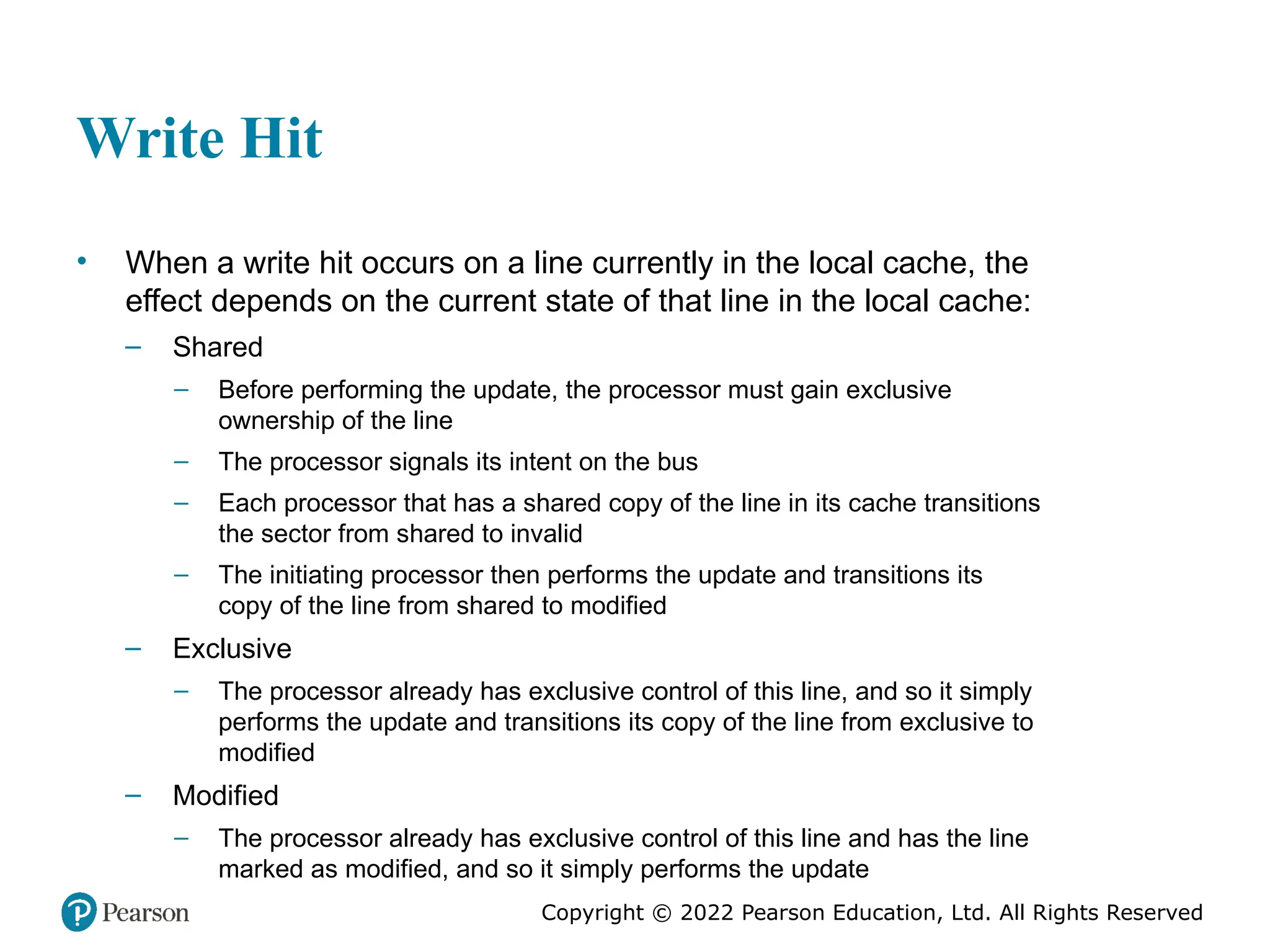
#27 Figure 20.9 is the flowchart when the initiator performs a write to a write-back cache. If the block containing the word to be written is already in a line of the cache (hit), the initiator updates the line in the cache and sets the line state to M. It also signals a write hit to participants, who set that line to invalid. If the desired line is not in the cache, the initiator signals a write miss (WM) to the other participants. The rest of the flowchart is similar to that of Figure 20.8.
#28 The most important measure of performance for a processor is the rate at which it executes instructions. This can be expressed as MIPS rate = f * IPC where f is the processor clock frequency, in MHz, and IPC (instructions per cycle) is the average number of instructions executed per cycle. Accordingly, designers have pursued the goal of increased performance on two fronts: increasing clock frequency and increasing the number of instructions executed or, more properly, the number of instructions that complete during a processor cycle. As we have seen in earlier chapters, designers have increased IPC by using an instruction pipeline and then by using multiple parallel instruction pipelines in a superscalar architecture. With pipelined and multiple-pipeline designs, the principal problem is to maximize the utilization of each pipeline stage. To improve throughput, designers have created ever more complex mechanisms, such as executing some instructions in a different order from the way they occur in the instruction stream and beginning execution of instructions that may never be needed. But as was discussed in Section 2.2, this approach may be reaching a limit due to complexity and power consumption concerns. An alternative approach, which allows for a high degree of instruction-level parallelism without increasing circuit complexity or power consumption, is called multithreading. In essence, the instruction stream is divided into several smaller streams, known as threads, such that the threads can be executed in parallel. The variety of specific multithreading designs, realized in both commercial systems and experimental systems, is vast. In this section, we give a brief survey of the major concepts.
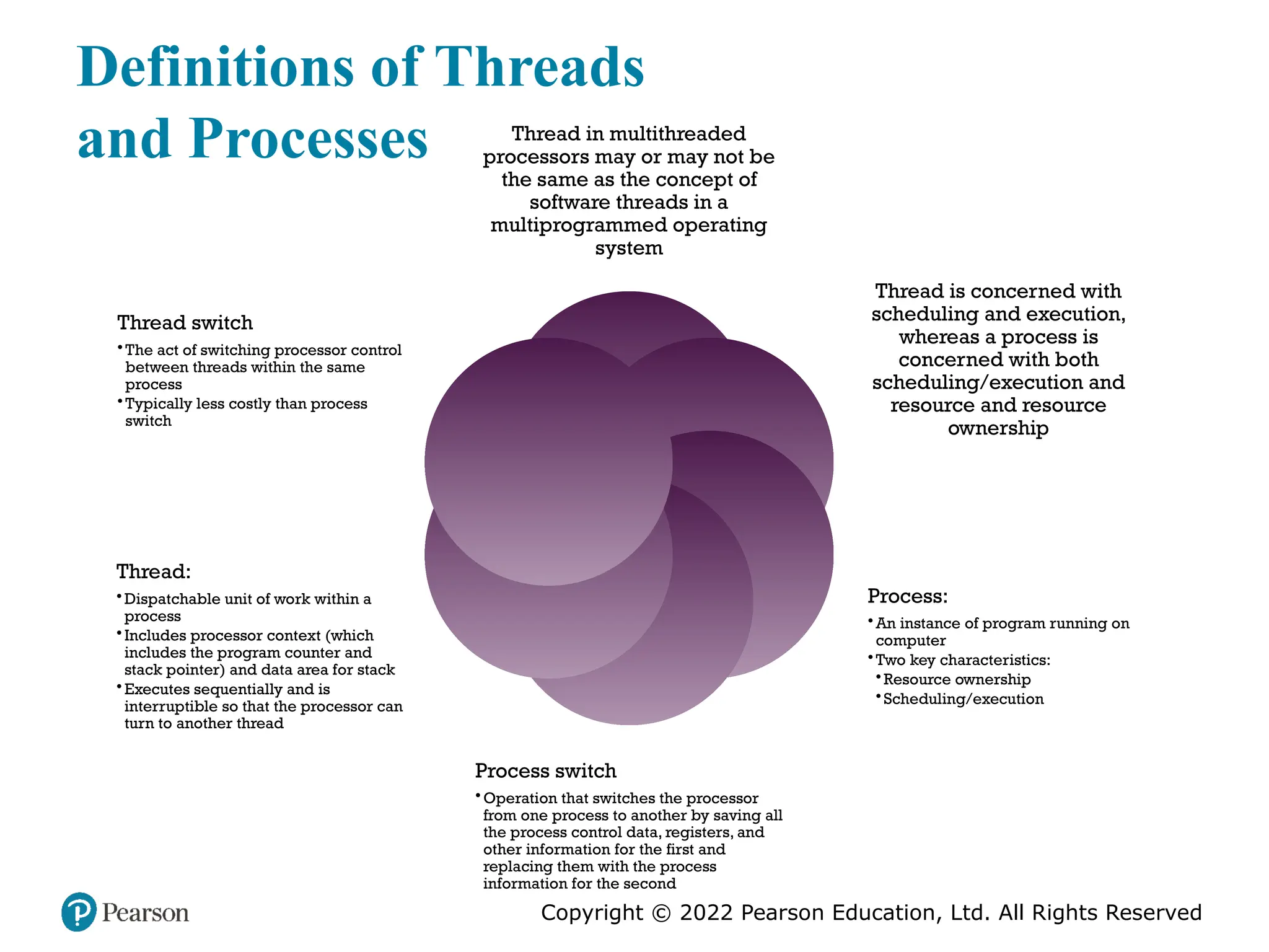
#29 The concept of thread used in discussing multithreaded processors may or may not be the same as the concept of software threads in a multiprogrammed operating system. It will be useful to define terms briefly: • Process: An instance of a program running on a computer. A process embodies two key characteristics: —Resource ownership: A process includes a virtual address space to hold the process image; the process image is the collection of program, data, stack, and attributes that define the process. From time to time, a process may be allocated control or ownership of resources, such as main memory, I/O channels, I/O devices, and files. —Scheduling/execution: The execution of a process follows an execution path (trace) through one or more programs. This execution may be inter- leaved with that of other processes. Thus, a process has an execution state (Running, Ready, etc.) and a dispatching priority and is the entity that is scheduled and dispatched by the operating system. Process switch: An operation that switches the processor from one process to another, by saving all the process control data, registers, and other information for the first and replacing them with the process information for the second. Thread: A dispatchable unit of work within a process. It includes a processor context (which includes the program counter and stack pointer) and its own data area for a stack (to enable subroutine branching). A thread executes sequentially and is interruptible so that the processor can turn to another thread. Thread switch: The act of switching processor control from one thread to an- other within the same process. Typically, this type of switch is much less costly than a process switch. Thus, a thread is concerned with scheduling and execution, whereas a process is concerned with both scheduling/execution and resource ownership. The multiple threads within a process share the same resources. This is why a thread switch is much less time consuming than a process switch. Traditional operating systems, such as earlier versions of UNIX, did not support threads. Most modern operating systems, such as Linux, other versions of UNIX, and Windows, do support thread. A distinction is made between user-level threads, which are visible to the application program, and kernel-level threads, which are visible only to the operating sys- tem. Both of these may be referred to as explicit threads, defined in software.
#30 All of the commercial processors and most of the experimental processors so far have used explicit multithreading. These systems concurrently execute instructions from different explicit threads, either by interleaving instructions from different threads on shared pipelines or by parallel execution on parallel pipelines. Implicit multithreading refers to the concurrent execution of multiple threads extracted from a single sequential program. These implicit threads may be defined either statically by the compiler or dynamically by the hardware. In the remainder of this section we consider explicit multithreading.
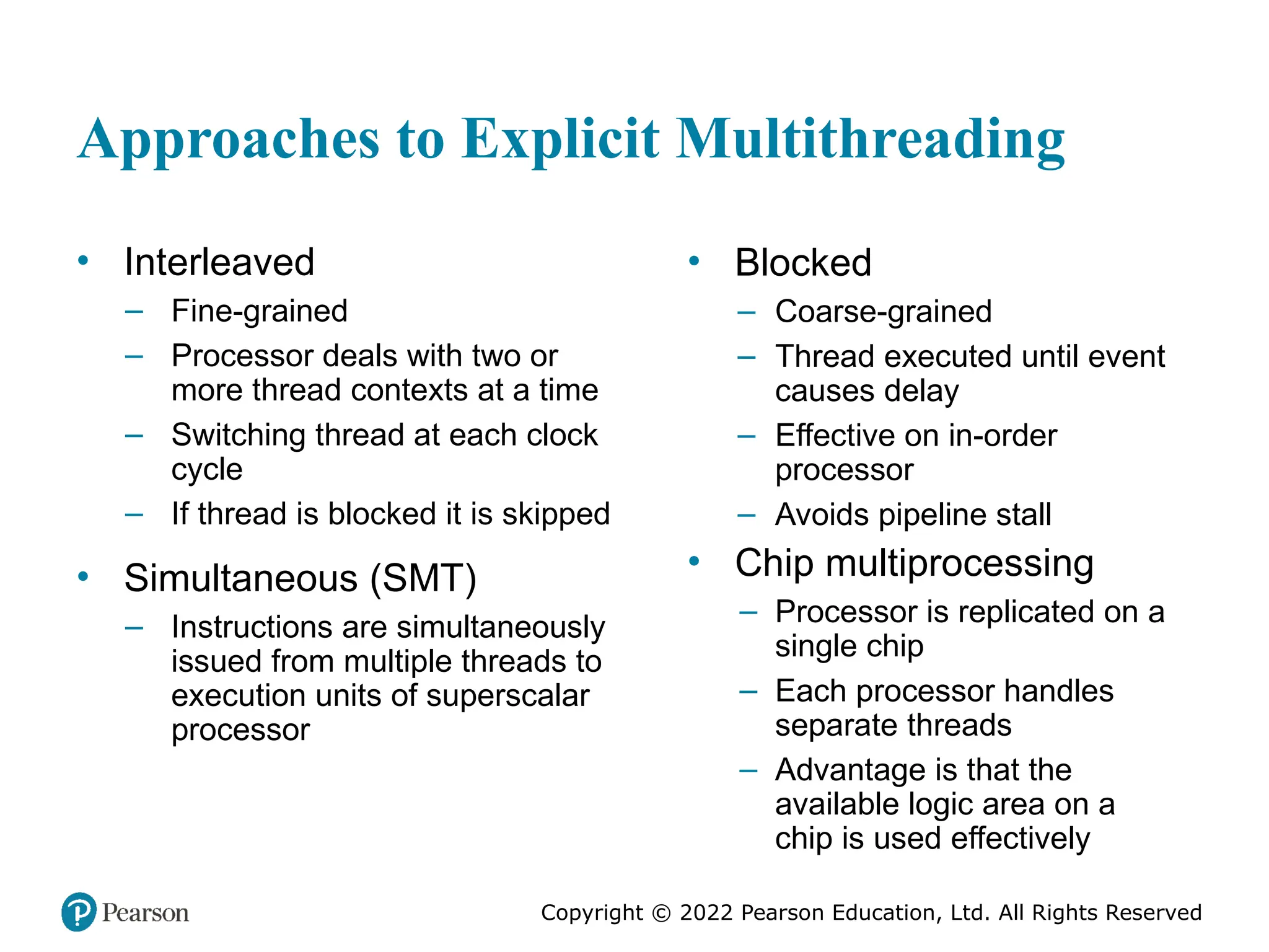
#31 Broadly speaking, there are four principal approaches to multithreading: • Interleaved multithreading: This is also known as fine-grained multithreading. The processor deals with two or more thread contexts at a time, switching from one thread to another at each clock cycle. If a thread is blocked because of data dependencies or memory latencies, that thread is skipped and a ready thread is executed. Blocked multithreading: This is also known as coarse-grained multithreading. The instructions of a thread are executed successively until an event occurs that may cause delay, such as a cache miss. This event induces a switch to another thread. This approach is effective on an in-order processor that would stall the pipeline for a delay event such as a cache miss. Simultaneous multithreading (SMT): Instructions are simultaneously issued from multiple threads to the execution units of a superscalar processor. This combines the wide superscalar instruction issue capability with the use of multiple thread contexts. Chip multiprocessing: In this case, the entire processor is replicated on a single chip and each processor handles separate threads. The advantage of this approach is that the available logic area on a chip is used effectively without depending on ever-increasing complexity in pipeline design.
#32 For the first two approaches, instructions from different threads are not executed simultaneously. Instead, the processor is able to rapidly switch from one thread to another, using a different set of registers and other context information. This results in a better utilization of the processor’s execution resources and avoids a large penalty due to cache misses and other latency events. The SMT approach involves true simultaneous execution of instructions from different threads, using replicated execution resources. Chip multiprocessing also enables simultaneous execution of instructions from different threads. Figure 20.10, based on one in [UNGE02], illustrates some of the possible pipe- line architectures that involve multithreading and contrasts these with approaches that do not use multithreading. Each horizontal row represents the potential issue slot or slots for a single execution cycle; that is, the width of each row corresponds to the maximum number of instructions that can be issued in a single clock cycle. The vertical dimension represents the time sequence of clock cycles. An empty (shaded) slot represents an unused execution slot in one pipeline. A no-op is indicated by N. The first three illustrations in Figure 20.10show different approaches with a scalar (i.e., single-issue) processor: Single-threaded scalar: This is the simple pipeline found in traditional RISC and CISC machines, with no multithreading. Interleaved multithreaded scalar: This is the easiest multithreading approach to implement. By switching from one thread to another at each clock cycle, the pipeline stages can be kept fully occupied, or close to fully occupied. The hardware must be capable of switching from one thread context to another between cycles. • Blocked multithreaded scalar: In this case, a single thread is executed until a latency event occurs that would stop the pipeline, at which time the processor switches to another thread. Figure 20.10c shows a situation in which the time to perform a thread switch is one cycle, whereas Figure 20.10b shows that thread switching occurs in zero cycles. In the case of interleaved multithreading, it is assumed that there are no control or data dependencies between threads, which simplifies the pipeline design and therefore should allow a thread switch with no delay. However, depending on the specific design and implementation, block multithreading may require a clock cycle to perform a thread switch, as illustrated in Figure 20.10. This is true if a fetched instruction triggers the thread switch and must be discarded from the pipeline [UNGE03]. Although interleaved multithreading appears to offer better processor utilization than blocked multithreading, it does so at the sacrifice of single-thread performance. The multiple threads compete for cache resources, which raises the probability of a cache miss for a given thread. More opportunities for parallel execution are available if the processor can issue multiple instructions per cycle. Figures 20.10d through 20.10i illustrate a number of variations among processors that have hardware for issuing four instructions per cycle. In all these cases, only instructions from a single thread are issued in a single cycle. The following alternatives are illustrated: ■ Superscalar: This is the basic superscalar approach with no multithreading. Until relatively recently, this was the most powerful approach to providing parallelism within a processor. Note that during some cycles, not all of the available issue slots are used. During these cycles, less than the maximum number of instructions is issued; this is referred to as horizontal loss . During other instruction cycles, no issue slots are used; these are cycles when no instructions can be issued; this is referred to as vertical loss . ■ Interleaved multithreading superscalar: During each cycle, as many instructions as possible are issued from a single thread. With this technique, potential delays due to thread switches are eliminated, as previously discussed. However, the number of instructions issued in any given cycle is still limited by dependencies that exist within any given thread. ■ Blocked multithreaded superscalar: Again, instructions from only one thread may be issued during any cycle, and blocked multithreading is used. ■ Very long instruction word (VLIW): A VLIW architecture, such as IA- 64, places multiple instructions in a single word. Typically, a VLIW is constructed by the compiler, which places operations that may be executed in parallel in the same word. In a simple VLIW machine (Figure 20.10g), if it is not possible to completely fill the word with instructions to be issued in parallel, no-ops are used. ■ Interleaved multithreading VLIW: This approach should provide similar efficiencies to those provided by interleaved multithreading on a superscalar architecture. ■ Blocked multithreaded VLIW: This approach should provide similar efficiencies to those provided by blocked multithreading on a superscalar architecture. The final two approaches illustrated in Figure 20.10 enable the parallel, simultaneous execution of multiple threads: ■ Simultaneous multithreading: Figure 20.10i shows a system capable of issuing 8 instructions at a time. If one thread has a high degree of instruction- level parallelism, it may on some cycles be able fill all of the horizontal slots. On other cycles, instructions from two or more threads may be issued. If sufficient threads are active, it should usually be possible to issue the maximum number of instructions on each cycle, providing a high level of efficiency. ■ Chip multiprocessor (multicore): Figure 20.10k shows a chip containing four cores, each of which has a two-issue superscalar processor. Each core is assigned a thread, from which it can issue up to two instructions per cycle. We discuss multicore computers in Chapter 21. Comparing Figures 20.10i and 20.10k, we see that a chip multiprocessor with the same instruction issue capability as an SMT cannot achieve the same degree of Instruction-level parallelism. This is because the chip multiprocessor is not able to hide latencies by issuing instructions from other threads. On the other hand, the chip multiprocessor should outperform a superscalar processor with the same instruction issue capability, because the horizontal losses will be greater for the superscalar processor. In addition, it is possible to use multithreading within each of the cores on a chip multiprocessor, and this is done on some contemporary machines.
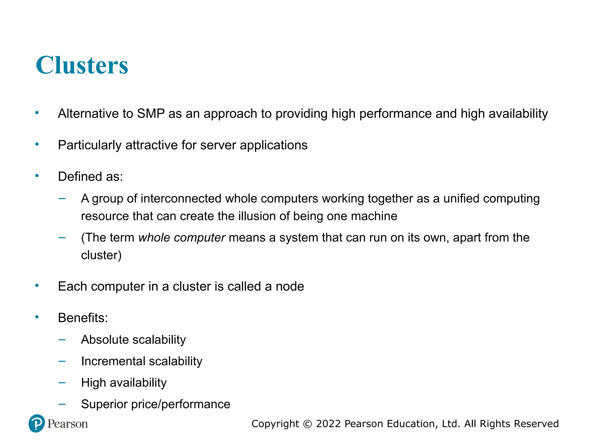
#33 An important and relatively recent development computer system design is clustering. Clustering is an alternative to symmetric multiprocessing as an approach to providing high performance and high availability and is particularly attractive for server applications. We can define a cluster as a group of interconnected, whole computers working together as a unified computing resource that can create the illusion of being one machine. The term whole computer means a system that can run on its own, apart from the cluster; in the literature, each computer in a cluster is typically referred to as a node. [BREW97] lists four benefits that can be achieved with clustering. These can also be thought of as objectives or design requirements: • Absolute scalability: It is possible to create large clusters that far surpass the power of even the largest standalone machines. A cluster can have tens, hundreds, or even thousands of machines, each of which is a multiprocessor. • Incremental scalability: A cluster is configured in such a way that it is possible to add new systems to the cluster in small increments. Thus, a user can start out with a modest system and expand it as needs grow, without having to go through a major upgrade in which an existing small system is replaced with a larger system. • High availability: Because each node in a cluster is a standalone computer, the failure of one node does not mean loss of service. In many products, fault tolerance is handled automatically in software. • Superior price/performance: By using commodity building blocks, it is possible to put together a cluster with equal or greater computing power than a single large machine, at much lower cost.
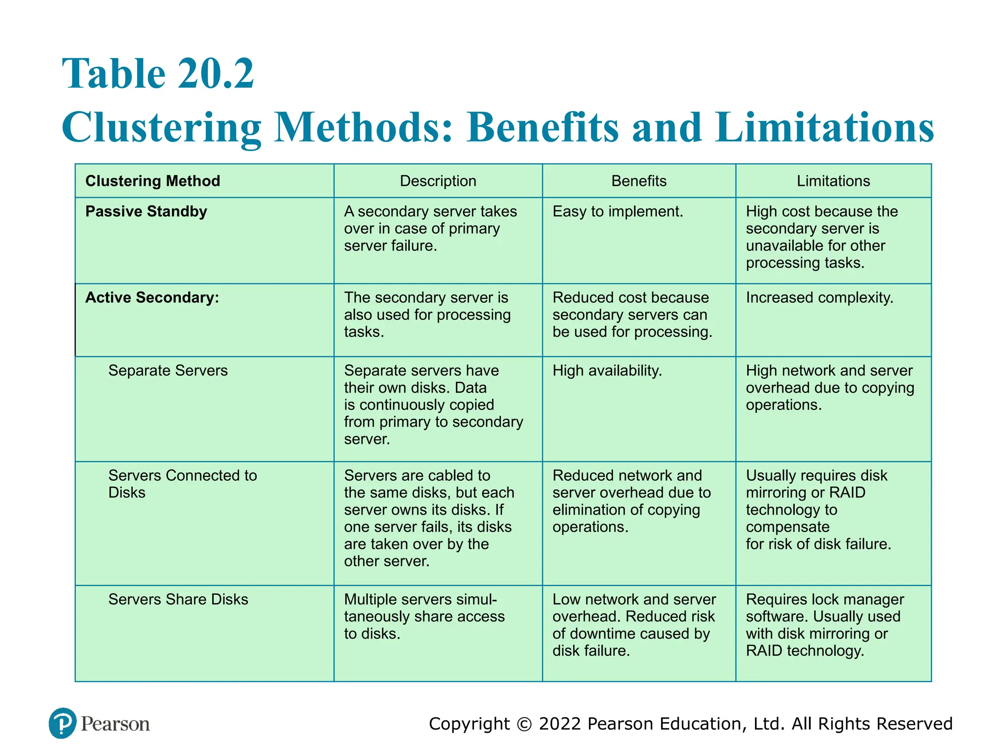
#34 In the literature, clusters are classified in a number of different ways. Perhaps the simplest classification is based on whether the computers in a cluster share access to the same disks. Figure 20.11a shows a two-node cluster in which the only interconnection is by means of a high-speed link that can be used for message exchange to coordinate cluster activity. The link can be a LAN that is shared with other computers that are not part of the cluster or the link can be a dedicated interconnection facility. In the latter case, one or more of the computers in the cluster will have a link to a LAN or WAN so that there is a connection between the server cluster and remote client systems. Note that in the figure, each computer is depicted as being a multiprocessor. This is not necessary but does enhance both performance and availability. In the simple classification depicted in Figure 20.11, the other alternative is a shared-disk cluster. In this case, there generally is still a message link between nodes. In addition, there is a disk subsystem that is directly linked to multiple computers within the cluster. In this figure, the common disk subsystem is a RAID system. The use of RAID or some similar redundant disk technology is common in clusters so that the high availability achieved by the presence of multiple computers is not compromised by a shared disk that is a single point of failure. A common, older method, known as passive standby , is simply to have one computer handle all of the processing load while the other computer remains inactive, standing by to take over in the event of a failure of the primary. To coordinate the machines, the active, or primary, system periodically sends a “heartbeat” message to the standby machine. Should these messages stop arriving, the standby assumes that the primary server has failed and puts itself into operation. This approach increases availability but does not improve performance. Further, if the only information that is exchanged between the two systems is a heartbeat message, and if the two systems do not share common disks, then the standby provides a functional backup but has no access to the databases managed by the primary. The passive standby is generally not referred to as a cluster. The term cluster is reserved for multiple interconnected computers that are all actively doing processing while maintaining the image of a single system to the outside world. The term active secondary is often used in referring to this configuration. Three classifications of clustering can be identified: separate servers, shared nothing, and shared memory. In one approach to clustering, each computer is a separate server with its own disks and there are no disks shared between systems (Figure 20.11a). This arrangement provides high performance as well as high availability. In this case, some type of management or scheduling software is needed to assign incoming client requests to servers so that the load is balanced and high utilization is achieved. It is desirable to have a failover capability, which means that if a computer fails while executing an application, another computer in the cluster can pick up and complete the application. For this to happen, data must constantly be copied among systems so that each system has access to the current data of the other systems. The overhead of this data exchange ensures high availability at the cost of a performance penalty. To reduce the communications overhead, most clusters now consist of servers connected to common disks (Figure 20.11b). In one variation on this approach, called shared nothing , the common disks are partitioned into volumes, and each volume is owned by a single computer. If that computer fails, the cluster must be reconfigured so that some other computer has ownership of the volumes of the failed computer. It is also possible to have multiple computers share the same disks at the same time (called the shared disk approach), so that each computer has access to all of the volumes on all of the disks. This approach requires the use of some type of locking facility to ensure that data can only be accessed by one computer at a time.
#35 A clearer picture of the range of cluster options can be gained by looking at functional alternatives. Table 20.2 provides a useful classification along functional lines.
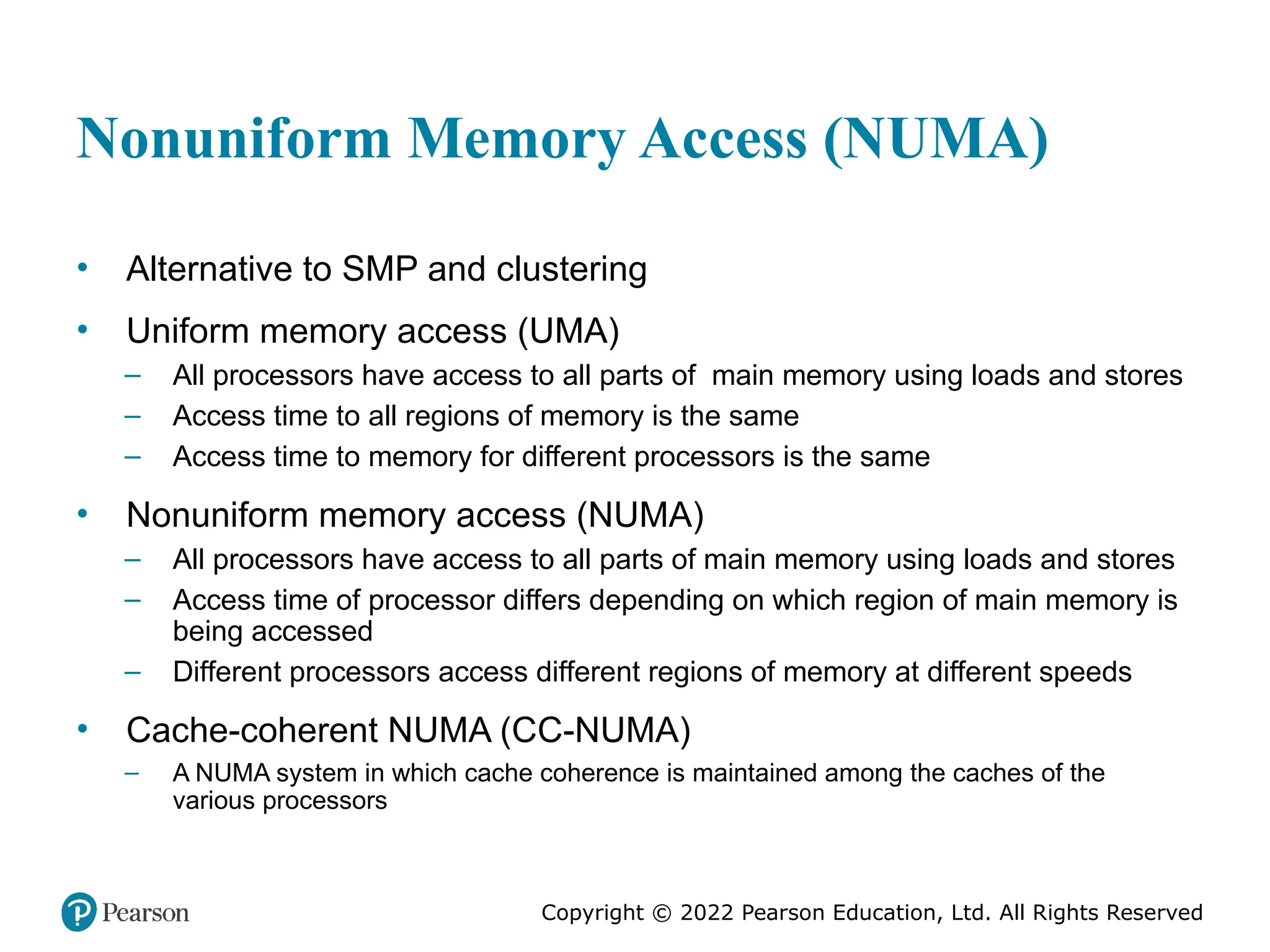
#36 In terms of commercial products, the two common approaches to providing a multiple-processor system to support applications are SMPs and clusters. For some years, another approach, known as nonuniform memory access (NUMA), has been the subject of research and commercial NUMA products are now available. Before proceeding, we should define some terms often found in the NUMA literature. • Uniform memory access (UMA): All processors have access to all parts of main memory using loads and stores. The memory access time of a processor to all regions of memory is the same. The access times experienced by different processors are the same. The SMP organization discussed in Sections 20.2 and 20.3 is UMA. • Nonuniform memory access (NUMA): All processors have access to all parts of main memory using loads and stores. The memory access time of a processor differs depending on which region of main memory is accessed. The last statement is true for all processors; however, for different processors, which memory regions are slower and which are faster differ. • Cache-coherent NUMA (CC-NUMA): A NUMA system in which cache coherence is maintained among the caches of the various processors. A NUMA system without cache coherence is more or less equivalent to a cluster. The commercial products that have received much attention recently are CC-NUMA systems, which are quite distinct from both SMPs and clusters. Usually, but unfortunately not always, such systems are in fact referred to in the commercial literature as CC-NUMA systems.
#37 With an SMP system, there is a practical limit to the number of processors that can be used. An effective cache scheme reduces the bus traffic between any one processor and main memory. As the number of processors increases, this bus traffic also increases. Also, the bus is used to exchange cache-coherence signals, further adding to the burden. At some point, the bus becomes a performance bottleneck. Performance degradation seems to limit the number of processors in an SMP configuration to somewhere between 16 and 64 processors. For example, Silicon Graphics’ Power Challenge SMP is limited to 64 R10000 processors in a single system; beyond this number performance degrades substantially. The processor limit in an SMP is one of the driving motivations behind the development of cluster systems. However, with a cluster, each node has its own private main memory; applications do not see a large global memory. In effect, coherency is maintained in software rather than hardware. This memory granularity affects performance and, to achieve maximum performance, software must be tailored to this environment. One approach to achieving large-scale multiprocessing while retaining the flavor of SMP is NUMA. The objective with NUMA is to maintain a transparent system wide memory while permitting multiple multiprocessor nodes, each with its own bus or other internal interconnect system.
#38 Figure 20.12 depicts a typical CC-NUMA organization. There are multiple independent nodes, each of which is, in effect, an SMP organization. Thus, each node contains multiple processors, each with its own L1 and L2 caches, plus main memory. The node is the basic building block of the overall CC-NUMA organization. For example, each Silicon Graphics Origin node includes two MIPS R10000 processors; each Sequent NUMA-Q node includes four Pentium II processors. The nodes are interconnected by means of some communications facility, which could be a switching mechanism, a ring, or some other networking facility. Each node in the CC-NUMA system includes some main memory. From the point of view of the processors, however, there is only a single addressable memory, with each location having a unique system wide address. When a processor initiates a memory access, if the requested memory location is not in that processor’s cache, then the L2 cache initiates a fetch operation. If the desired line is in the local portion of the main memory, the line is fetched across the local bus. If the desired line is in a remote portion of the main memory, then an automatic request is sent out to fetch that line across the interconnection network, deliver it to the local bus, and then deliver it to the requesting cache on that bus. All of this activity is automatic and transparent to the processor and its cache. In this configuration, cache coherence is a central concern. Although implementations differ as to details, in general terms we can say that each node must maintain some sort of directory that gives it an indication of the location of various portions of memory and also cache status information.
#39 The main advantage of a CC-NUMA system is that it can deliver effective performance at higher levels of parallelism than SMP, without requiring major software changes. With multiple NUMA nodes, the bus traffic on any individual node is limited to a demand that the bus can handle. However, if many of the memory accesses are to remote nodes, performance begins to break down. There is reason to believe that this performance breakdown can be avoided. First, the use of L1 and L2 caches is designed to minimize all memory accesses, including remote ones. If much of the software has good temporal locality, then remote memory accesses should not be excessive. Second, if the software has good spatial locality, and if virtual memory is in use, then the data needed for an application will reside on a limited number of frequently used pages that can be initially loaded into the memory local to the running application. The Sequent designers report that such spatial locality does appear in representative applications [LOVE96]. Finally, the virtual memory scheme can be enhanced by including in the operating system a page migration mechanism that will move a virtual memory page to a node that is frequently using it; the Silicon Graphics designers report success with this approach [WHIT97]. Even if the performance breakdown due to remote access is addressed, there are two other disadvantages for the CC-NUMA approach [PFIS98]. First, a CC-NUMA does not transparently look like an SMP; software changes will be required to move an operating system and applications from an SMP to a CC-NUMA system. These include page allocation, already mentioned, process allocation, and load balancing by the operating system. A second concern is that of availability. This is a rather complex issue and depends on the exact implementation of the CC-NUMA system; the interested reader is referred to [PFIS98].