Error Correction in Computer Networks
Last Updated : 23 Sep, 2025
Once the errors are detected in the network, the deviated bits sequence needs to be replaced with the right bit sequence so that the receiver can accept the data and process it. This method is called Error Correction. We can correct the errors in the Network in two different ways which are listed below:
- Forward Error Correction: In this Error Correction Scenario, the receiving end is responsible for correcting the network error. There is no need for retransmission of the data from the sender’s side.
- Backward Error Correction: the sender is responsible for retransmitting the data if errors are detected by the receiver. The receiver signals the sender to resend the corrupted data or the entire message to ensure accurate delivery.
However, there is one of the most widely used Error Correction methods which is called 'Hamming Code' which was designed by R.W. Hamming. Let us have a quick look at it.
Hamming Code Error Correction
In this method extra parity bits are appended to the message which are used by the receiver to correct the single bit error and multiple bit error. Consider the below example to understand this method in a better way.
Suppose the sender wants to transmit the message whose bit representation is ‘1011001.’ In this message:
- Total number of bits (d) = 7
- Total of redundant bits (r) = 4 (This is because the message has four 1’s in it)
- Thus, total bits (d+r) = 7 + 4 = 11
Also by convention the redundant bits are always placed in the places which are powers of 2. Now this message will take the format as shown below:

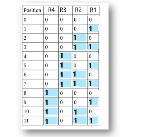
Therefore we have R1, R2, R3, and R4 as redundant bits which will be calculated according to the following rules:
- R1 includes all the positions whose binary representation has 1 in their least significant bit. Thus, R1 covers positions 1, 3, 5, 7, 9, 11.
- R2 includes all the positions whose binary representation has 1 in the second position from the least significant bit. Thus, R2 covers positions 2,3,6,7,10,11.
- R3 includes all the positions whose binary representation has 1 in the third position from the least significant bit. Hence, R3 covers positions 4, 5, 6, 7.
- R4 includes all the positions whose binary representation has 1 in the fourth position from the least significant bit due to which R4 covers positions 8,9,10,11.
These rules are illustrated below:
Now, we calculate the value of R1, R2, R3 and R4 as follows:
- Since the total number of 1s in all the bit positions corresponding to R1 is an even number. R1 = 0.
- Since the total number of 1s in all the bit positions corresponding to R2 is an odd number, R2= 1.
- Since the total number of 1s in all the bit positions corresponding to R3 is an odd number, R3= 1.
- Since the total number of 1s in all the bit positions corresponding to R4 is even, R4 = 0.
Therefore, the message to be transmitted becomes:

This message is transmitted at the receiver’s end. Suppose, bit 6 becomes corrupted and changes to 1. Then the message becomes ‘10101101110.’ So at the receiver’s end the number of 1’s in the respective bit positions of R1, R2, R3, and R4 is rechecked to correct the corrupted bit. This is done in the following steps: For all the parity bits we will check the
- For R1: bits 1, 3, 5, 7, 9, and 11 are checked. We can see that the number of 1’s in these bit positions is 4(even) so R1 = 0.
- For R2: bits 2,3,6,7,10,11 are checked. You can observe that the number of 1’s in these bit positions is 5(odd) so we get a R2 = 1.
- For R3: bits 4, 5, 6, and 7 are checked. We see that the number of 1’s in these bit positions is 3(odd). Hence, R3 = 1.
- For R8: bits 8,9,10,11 are observed. Here, the number of 1’s in these bit positions is 2 and that’s even so we get R4 = 0.
If we observe the Redundant bits, they give the binary number 0110 whose decimal representation is 6. The error in bit 6 has been successfully identified and corrected. By rechecking the parity bits, we could detect that R4 was not matching its expected value, pointing us to the corrupted bit. The bit 6 should have been 1, and after correcting it, the message is now error-free.
Explore
Computer Network Basics
Physical Layer
Data Link Layer
Network Layer
Transport Layer
Session Layer & Presentation Layer
Application Layer
Advanced Topics
Practice
My Profile