 p3rp0ul
1. Introduction
The following project is the amalgamation of multiple side quests from my ongoing SDR research. The hardware used in this embedded device was selected during the process of miniaturizing my pre-existing setup while adding packet radio transmission (TX) capabilities. The conception and design focused on portable operation, modularity, and ease of use.

Until this point, a suitcase housed two SDR receivers (one with a Low Noise Amplifier) and a GPS module, all plugged into a bulkier USB hub. A laptop running the required software was placed on the suitcase’s middle shelf, while RF-sensitive equipment was positioned in the lower compartment, shielded from RF noise. The LNA’s on/off and variable-voltage adjustment were accessible from the middle shelf. Although the suitcase was portable and could run the laptop from a 12 V car lighter port (with the inclusion of a laptop car charger), it remained bulky and cumbersome as a field-capable SDR platform.
2. Computer Aided Design
The goal of the CAD phase was to fit all required components into a pre-existing enclosure. It aided in visualizing the main components and verifying the feasibility of the proposed design and form factor. The enclosure provides protection for the included modules, RF shielding, and cooling via built-in fins.
The device has two main sides: the RF panel, where all coaxial connectors are located, and the Data panel, which provides access to the device internals via USB 3.0. On the Data panel, the voltage input of the integrated LNA is displayed, adjustable via a set screw (voltage is proportional to RX amplification), and controlled by an on/off switch.

From early design stages, it was clear that all USB dongles needed to be positioned parallel to each other, aligned along their largest sides. This determined the type of USB hub required to achieve the compact form factor. A sharp but permissible bend in the hub’s extension cable was necessary to make all components fit properly within the enclosure.
The slanted surface on which the USB connector is mounted gives the unit a more versatile form factor, allowing for desktop or vertical (e.g. harness) mounting, while providing enough clearance to view and adjust the LNA settings. The enclosure was modified accordingly, and a custom aluminum panel was designed and fabricated. SolidWorks 2024 was used for the CAD phase.
3. Hardware Setup
Enclosure
The enclosure used for this project originates from an AEG C-Net carryfax modem. This vintage contraption was intended for the Mercedes W126 from the 1990s as part of its communication equipment kit. Along with the matching power supply box, these units came into my possession years before the conception of this project and have since served as enclosure donors for two of my builds. Unfortunately, I never found the rest of the kit.
.")
The aluminum extrusion that forms the enclosure gives the device a robust feel and an impression of industrial or mission-critical equipment. The second device’s enclosure (depicted last) was used for a 4 W RX/TX amplifier, which will be covered in a future report.
 & Power supply (right).")
Internal Structure
The main data junction for all devices and modules embedded in this unit is a USB 3.0 hub with four Type-A ports and a 20 cm extension cable. The short extension cable connects to a WY24 female-to-female watertight panel connector, which has been modified by tapping into the 5 V line of the USB connection. This line is used to power an integrated 5 V to 1.2 - 24 V variable DC converter, which subsequently powers the LNA installed between one of the onboard SDRs and its corresponding BNC port on the RF panel. The LNA provides up to 30 dB of gain, across its 100 kHz - 2 GHz operating range....
Read more »
 Anthony Rasolofonirina
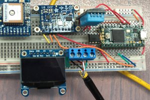
 Taras Kalapun
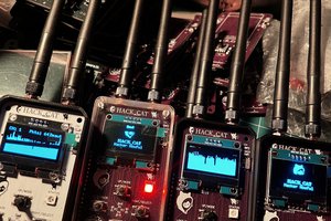
 hackernowful
 vishal soni