 Ben
BenFull build and testing
Part 1: Design and Impeller Selection
The foundation of any successful pump is the impeller. I ran extensive tests on various designs to determine the most efficient pumping characteristics. For those who want the full breakdown, check out the previous video below for the testing process.
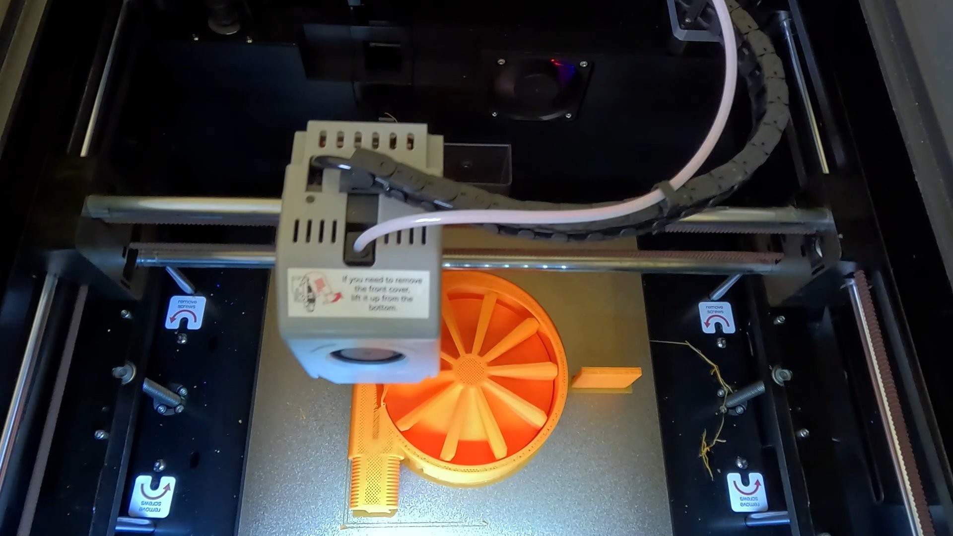
Ultimately, the best performer was a red 10-vane axial and radial design, which made it into the final print-in-place version.
The Print-in-Place Interface Trick
The key to a successful print-in-place (PiP) part is separating the moving components with a specific, tolerance gap.
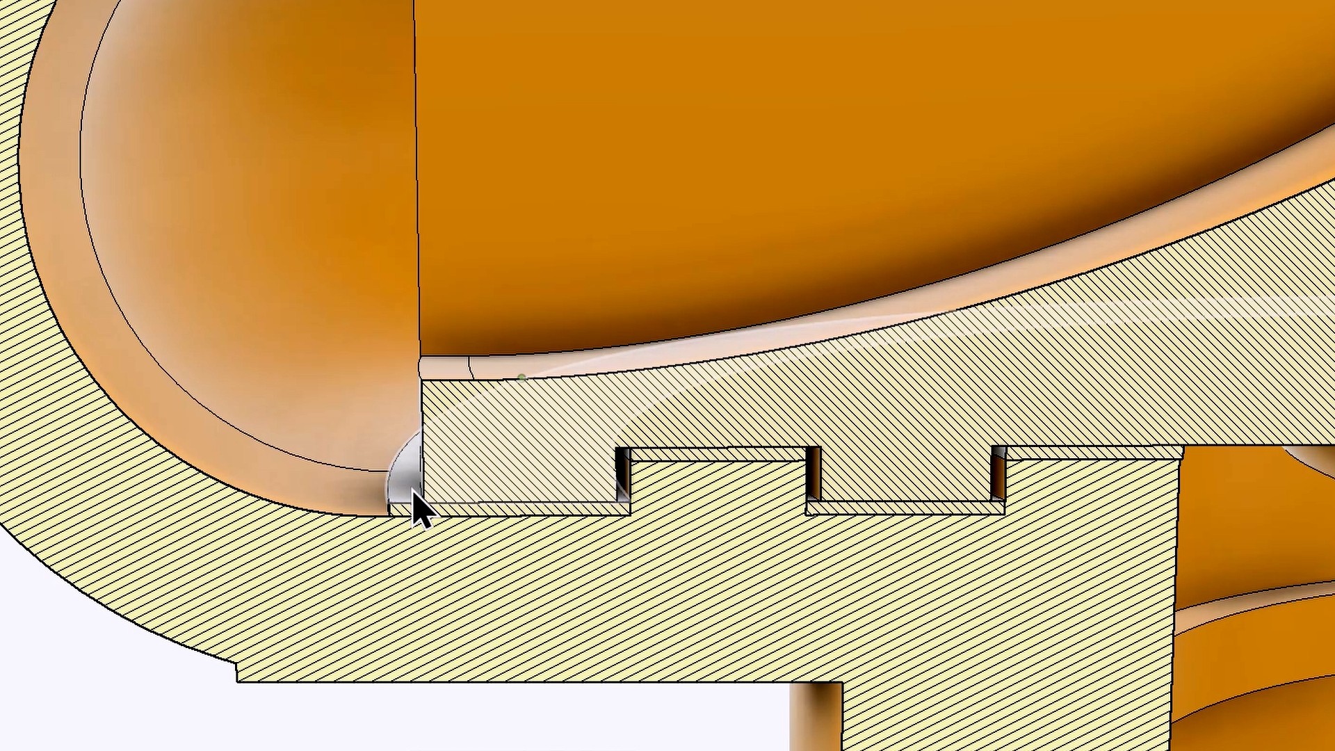
- Define the Separation: Add the parts (casing and impeller) you want to print together into your design software. The gap between the moving parts must be an exact multiple of your print layer height. For a 0.4 mm nozzle, I used an interface separation of two times the layer height, which is typically 0.4 mm.
- Create the Interface Body: Create a new component in your design called "Interface." This component is a solid body that exactly fills the space you want to maintain between the moving parts. This will be the space filled with the dissolvable support material.
- Export the Models:
- Export all components excluding the Interface component (this is your main part).
- Invert your selection and export only the Interface component (this is your soluble support part).
Part 2: Slicer Setup for Soluble Supports (on a Budget)
If you have a AMS or multi-head printer, this is straightforward. If you're like me, with a budget, single-head printer, we need to trick the slicer into performing manual filament changes for the soluble support material. These steps work for PrusaSlicer, and other PrusaSlicer-based slicers.
Slicer Configuration
- Enable Multiple Extruders: Go to the Print Settings tab and increase the number of extruders from 1 to two.
- Configure Retraction: Click on each extruder and set the retraction length to a conservative 1 mm.
- Tool Change G-Code: In the Custom G-code tab, modify the Tool change G-code block. Add either or both of the following commands to force a manual filament change at the start of each tool change cycle:
M0(Pauses the print until the user hits a button)M600(The extended G-code command for an assisted filament change)
- Wipe Tower and Shell: Under Print Settings -> Multiple Extruders, tick both the Wipe tower enable box and the Interface shell check box. The interface shell is crucial, as it ensures a solid, closed boundary is generated between the adjacent materials, resulting in a smooth, sealed surface when the support is removed.
Loading and Slicing the Parts
- Import Models: Import both your main
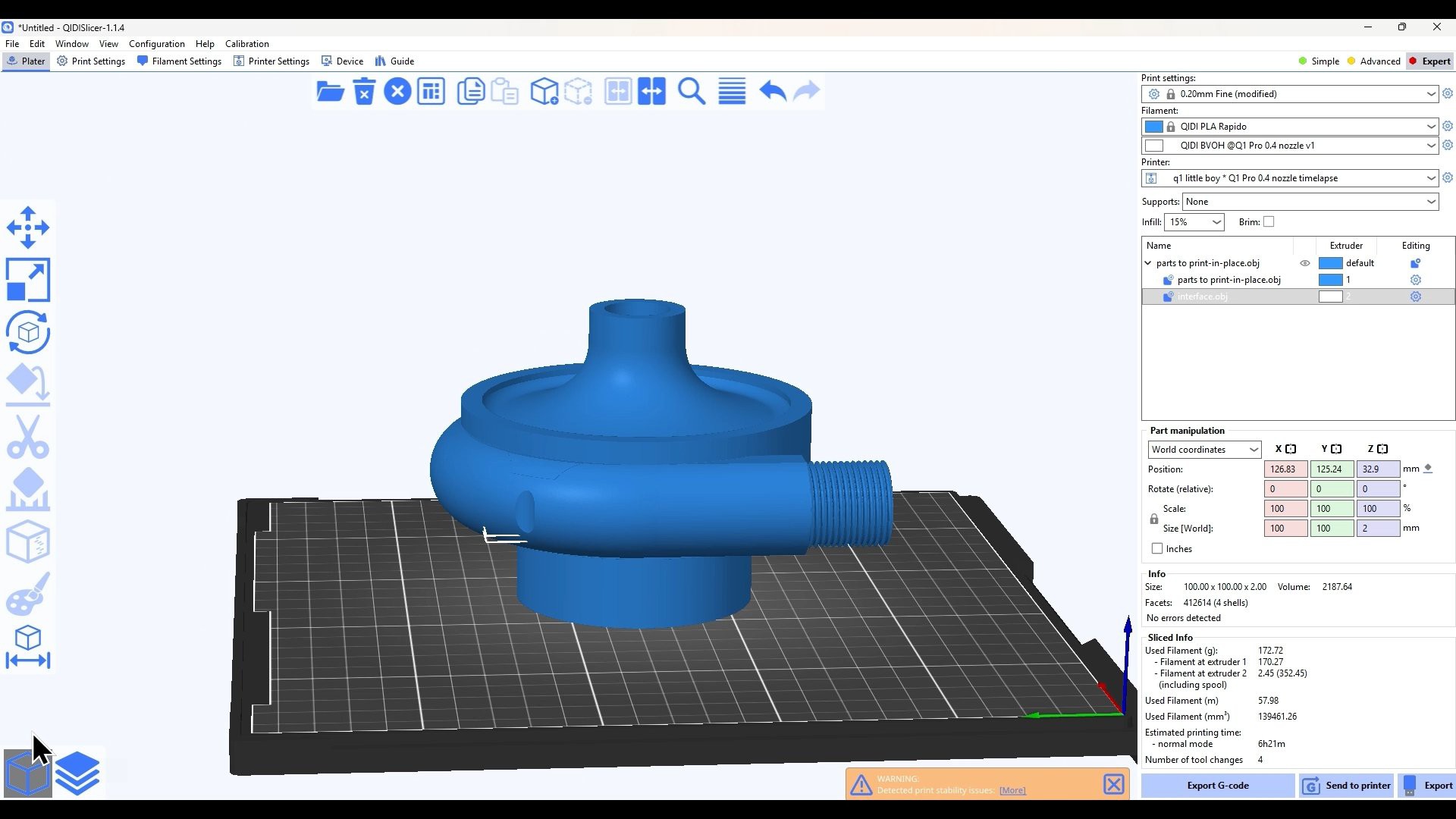
parts-to-print-in-placedesign and theinterfaceobject into the slicer. - Assign Extruders:
- Assign Extruder 1 (your main material, e.g., PLA) to the
parts-to-print-in-placemodel. - Assign Extruder 2 (your soluble material, e.g., BVOH, PVA) to the
interfacemodel.
- Assign Extruder 1 (your main material, e.g., PLA) to the
- Slice and Observe: After slicing, you'll see a small number of filament changes planned. Because the slicer prints both interface layers back-to-back (after the solid PLA layer and before the next solid PLA layer), you get four changes for the two interface levels in this design.
Part 3: Dissolving the Support and Final Assembly
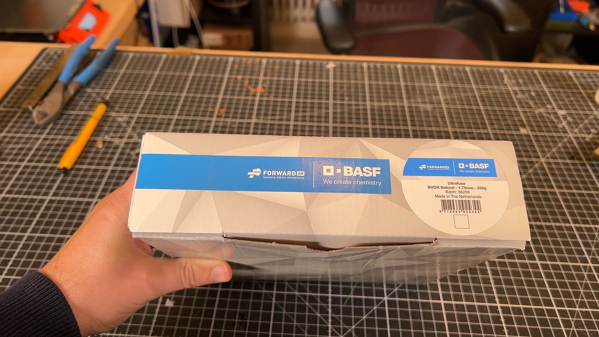
For the soluble support, I used BVOH, which is compatible with PLA.
BVOH Dissolution Test
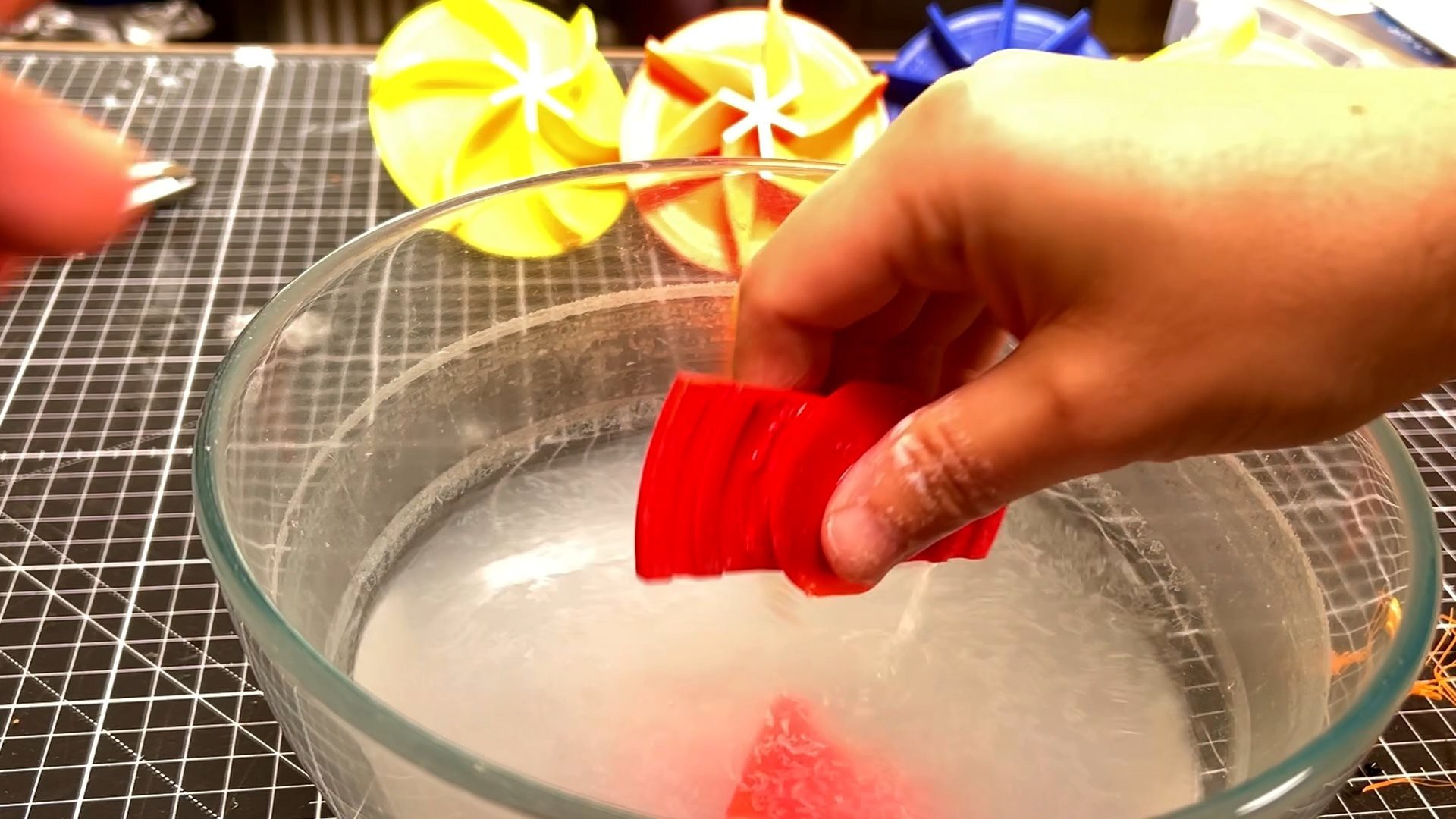
To get a baseline, I printed a small test area and submerged it in warm water.
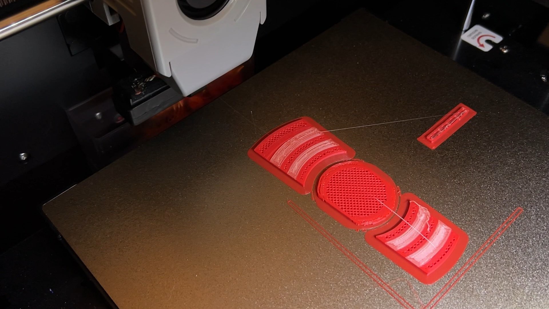
- 1 Hour: Minimal results.
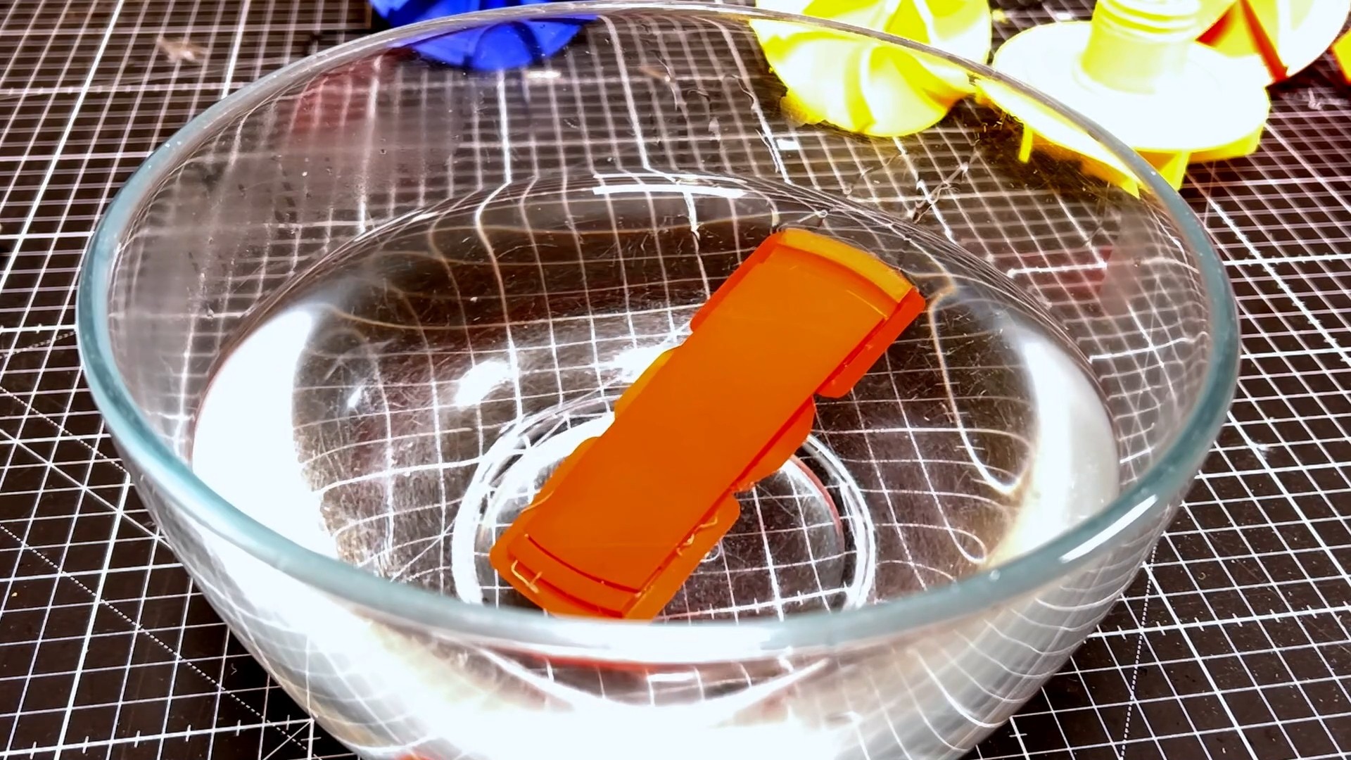
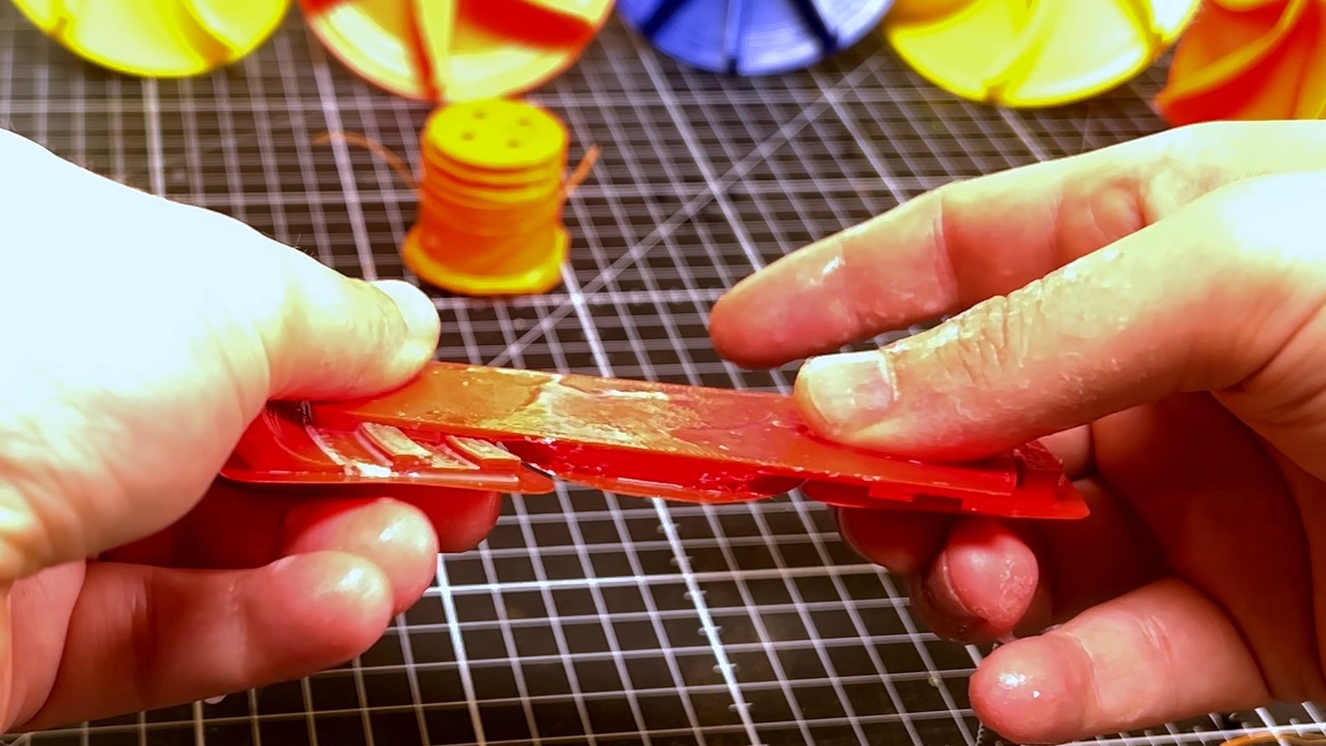
- 3 Days: Full release! The part separated cleanly, and the surface finish where the BVOH had been was incredibly smooth.
The impeller was perfectly free to spin.
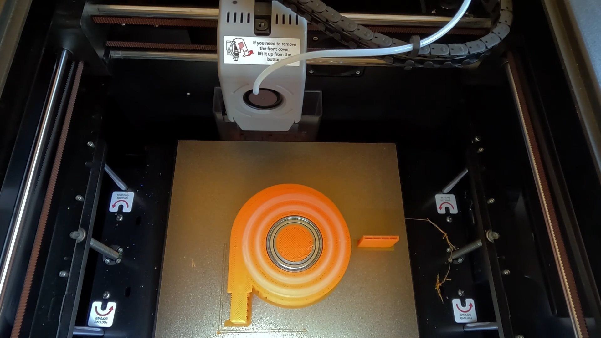
Full Print and Post-Processing
During the print installed the components—bearings, in-situ grease, and an O-ring.
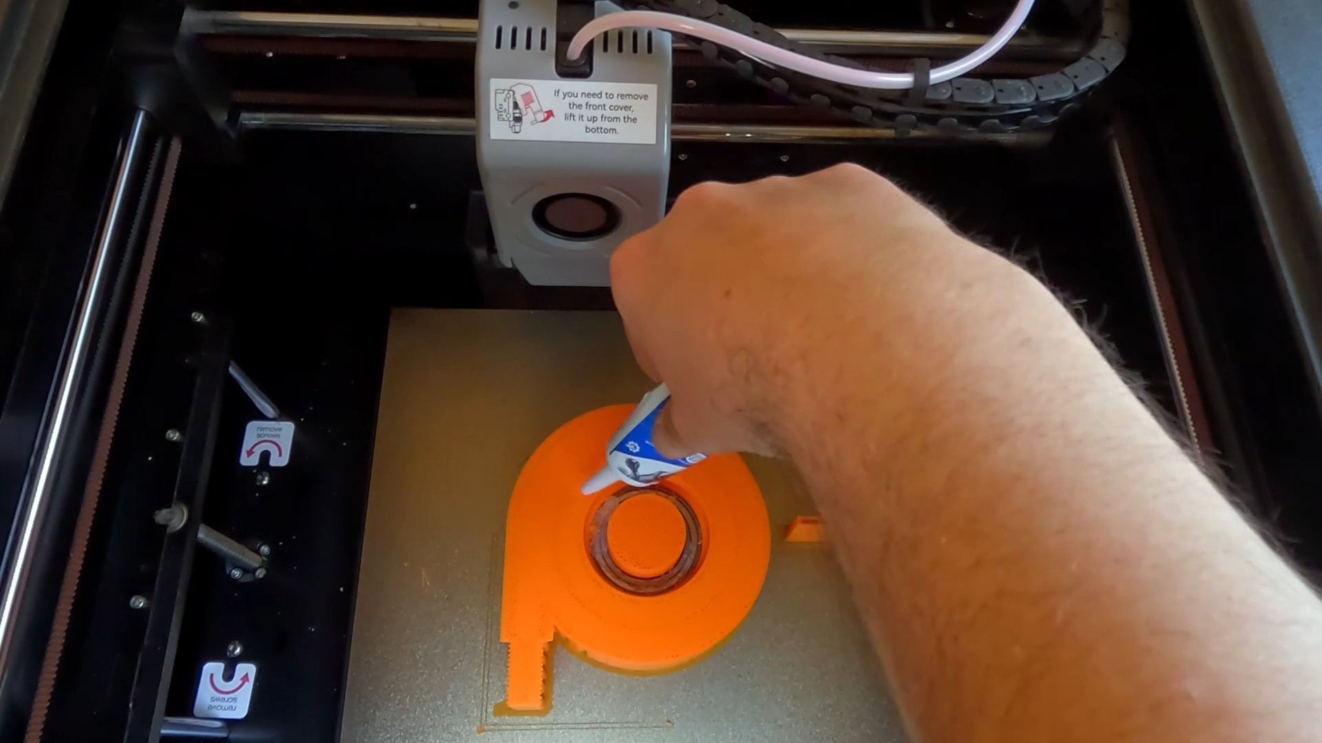
This was then followed by the four filament changes (two for the lower interface, two for the upper).
This was then submerged for the full 3 days...
Read more »