Close
0%
0%

PIP WATCH Version 2

Made the Revision 2 of my previous PIP WATCH PROJECT. Featuring a TTGO T Display S3 LONG and custom 3D printed Parts.

Similar projects worth following
Greetings everyone and welcome back. Meet PIP WATCH, a Pip-Boy-themed internet Watch that brings the retro-futuristic charm of the original device to your wrist, featuring the TTGO T DISPLAY ESP32 S3 LONG that has a super wide 640x180 Pixel screen that we are using as the main microcontroller and display for this project.

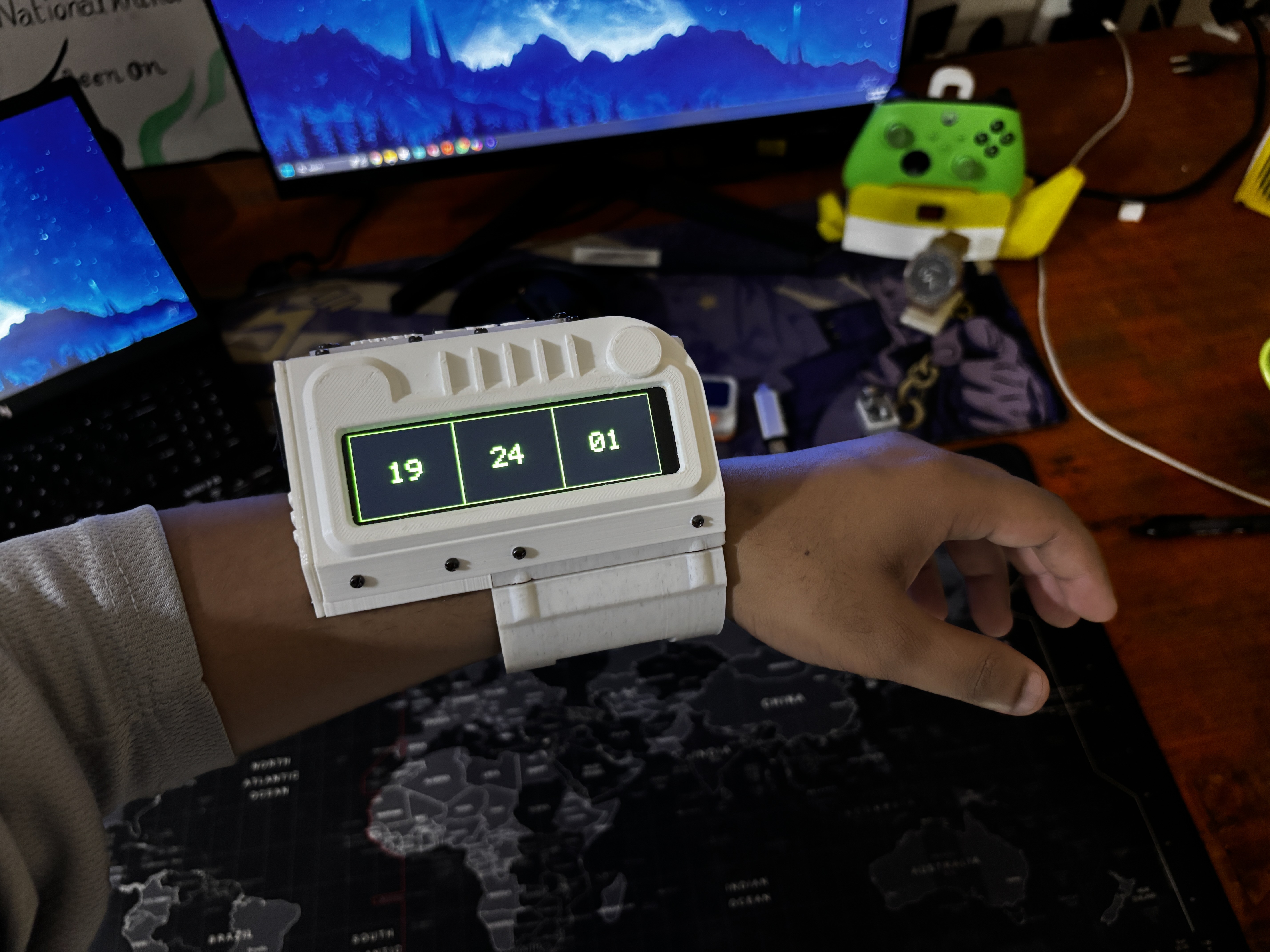
If you enjoy Fallout as much as I do, this PIP-WATCH is a great way to keep track of time in a Fallout style.

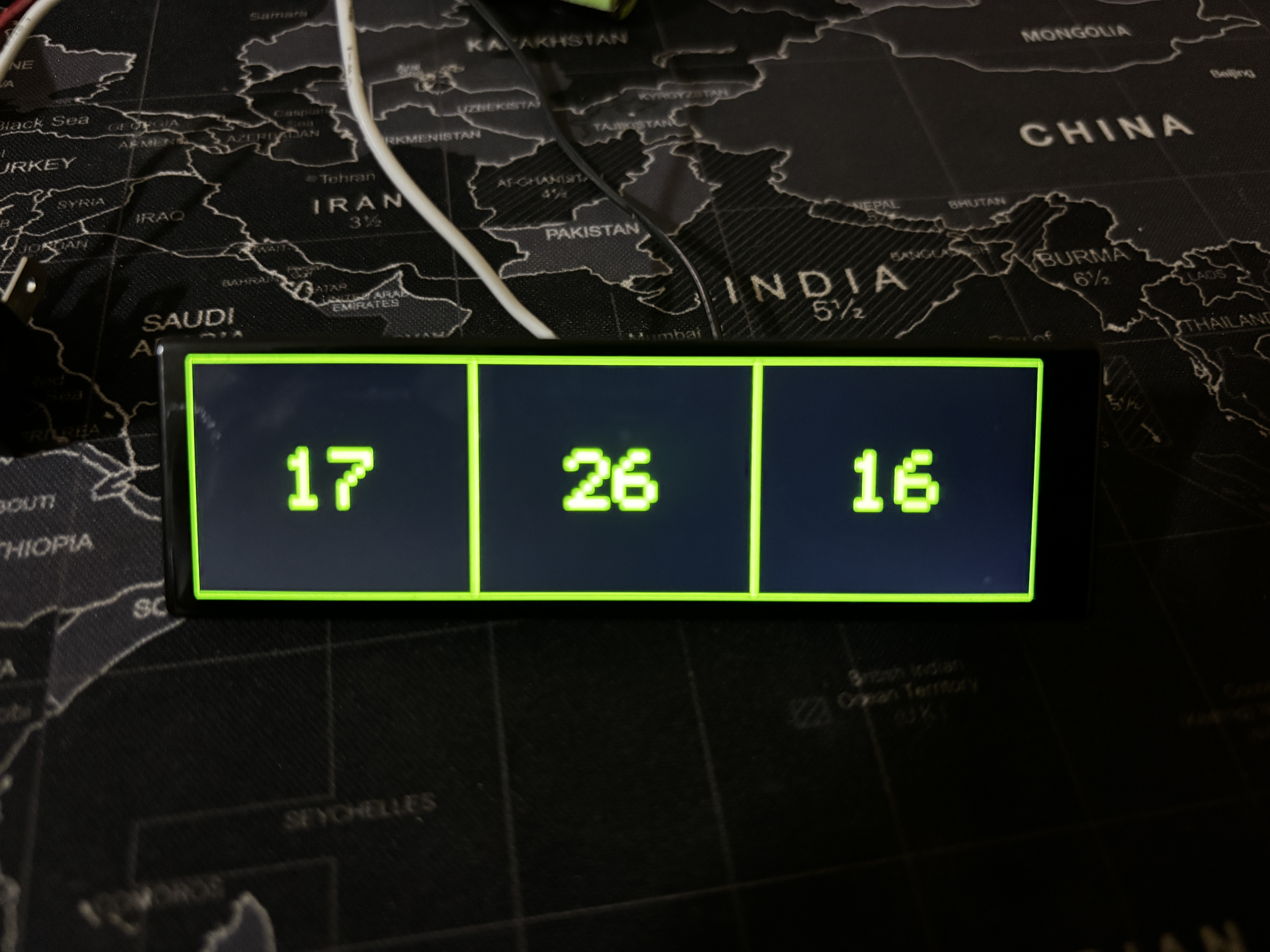
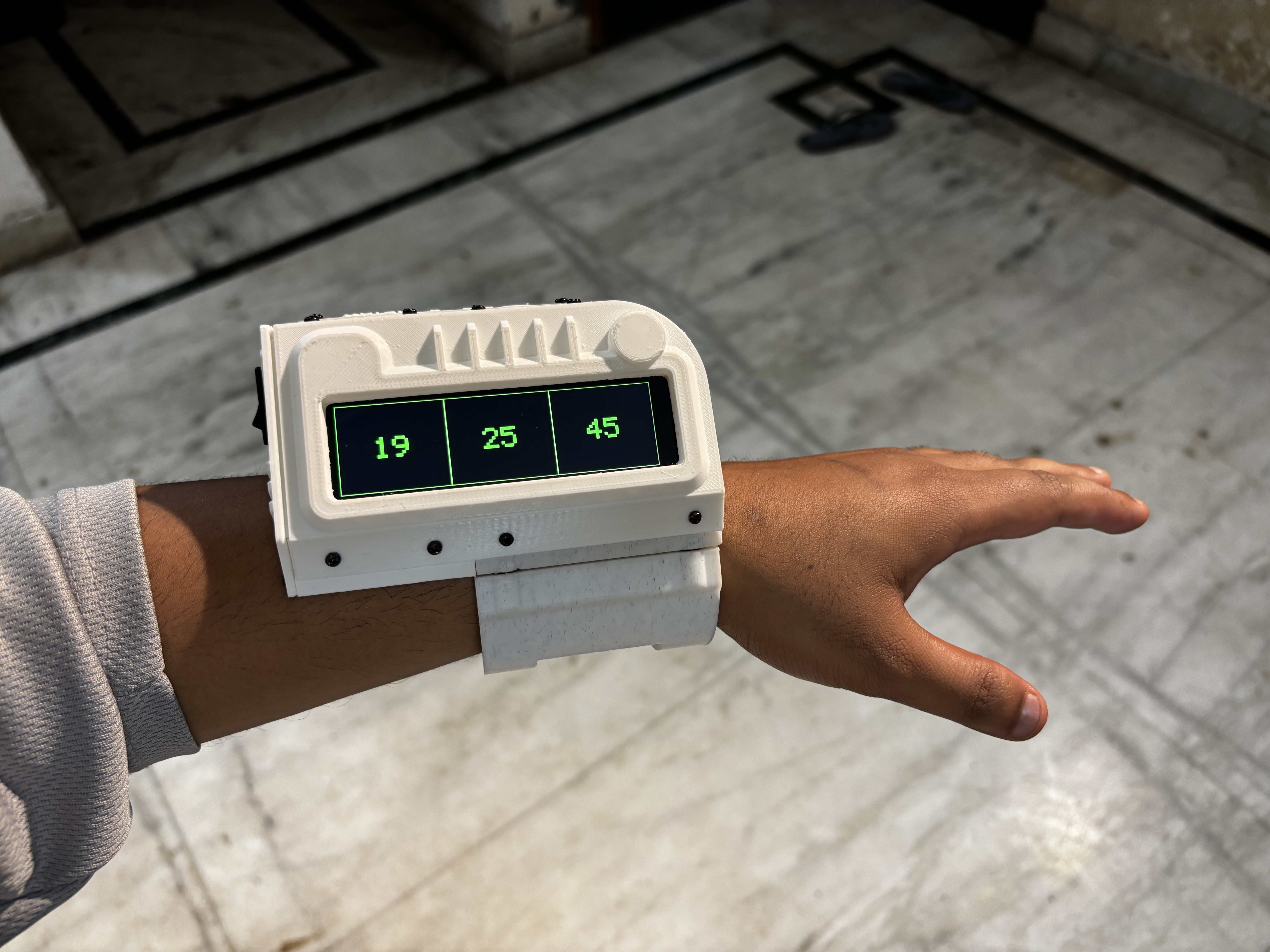
This is the Updated verssion of my previously created PIP WATCH V1 project that features a smaller GC9A01 Round display and a much smaller and different body than that of an actual PIP boy. In Version 2, we tried to model the device as close to its actual counterpart as possible, featuring the wide body design with a screen placed horizontally. The Clock funstuion remains the same in version 2; we are getting Time data from an NTP server and then it is being displayed on the screen.

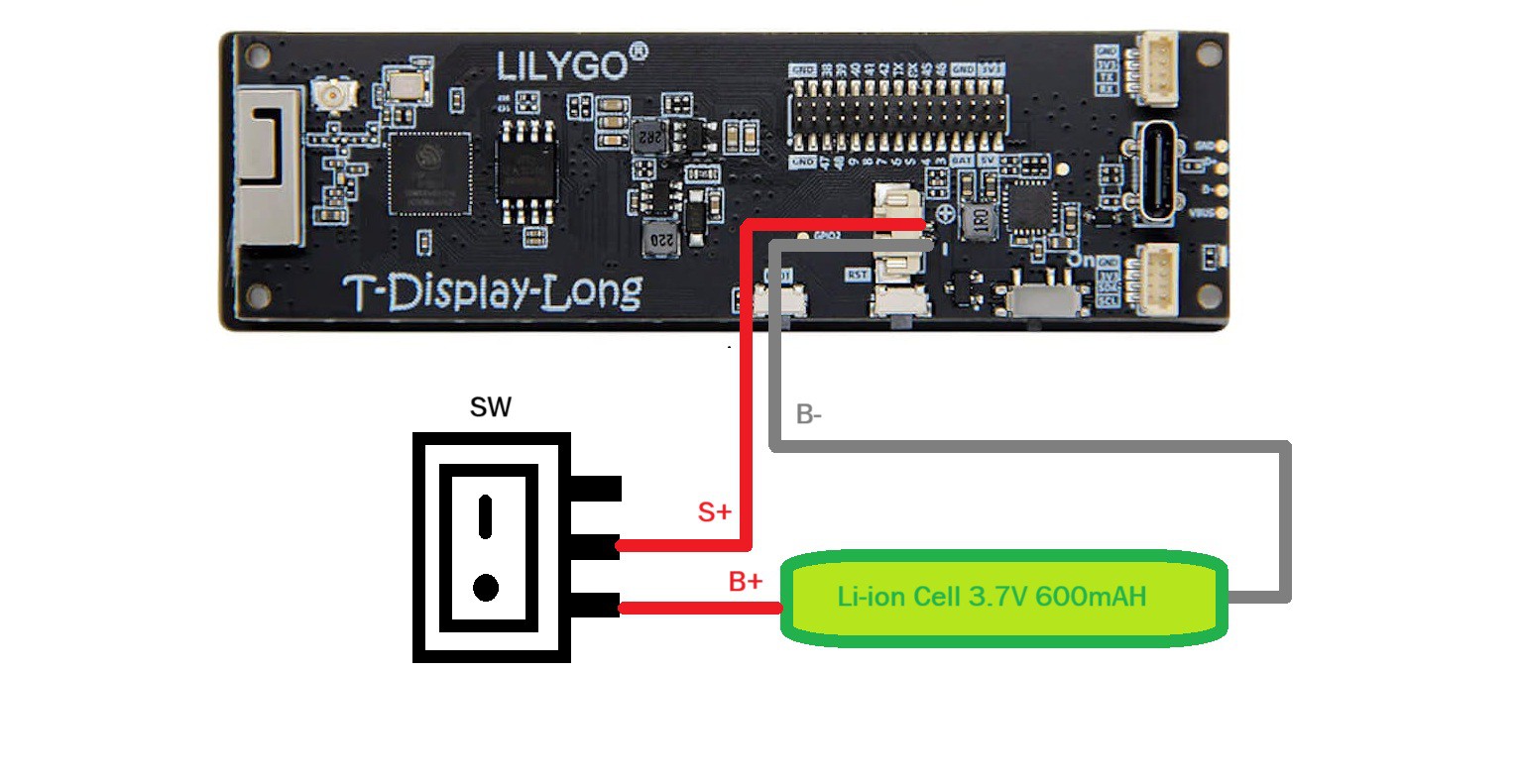
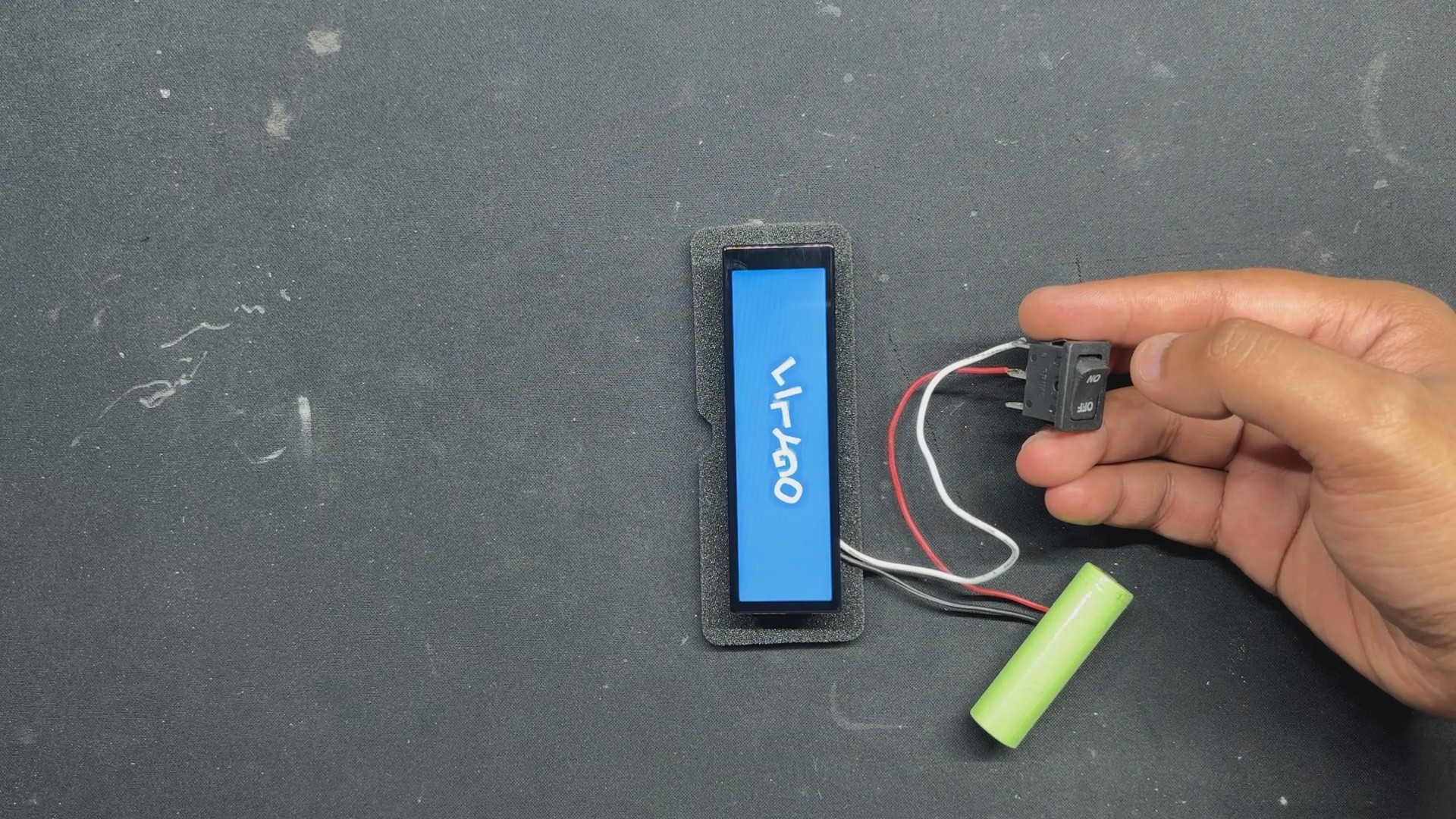
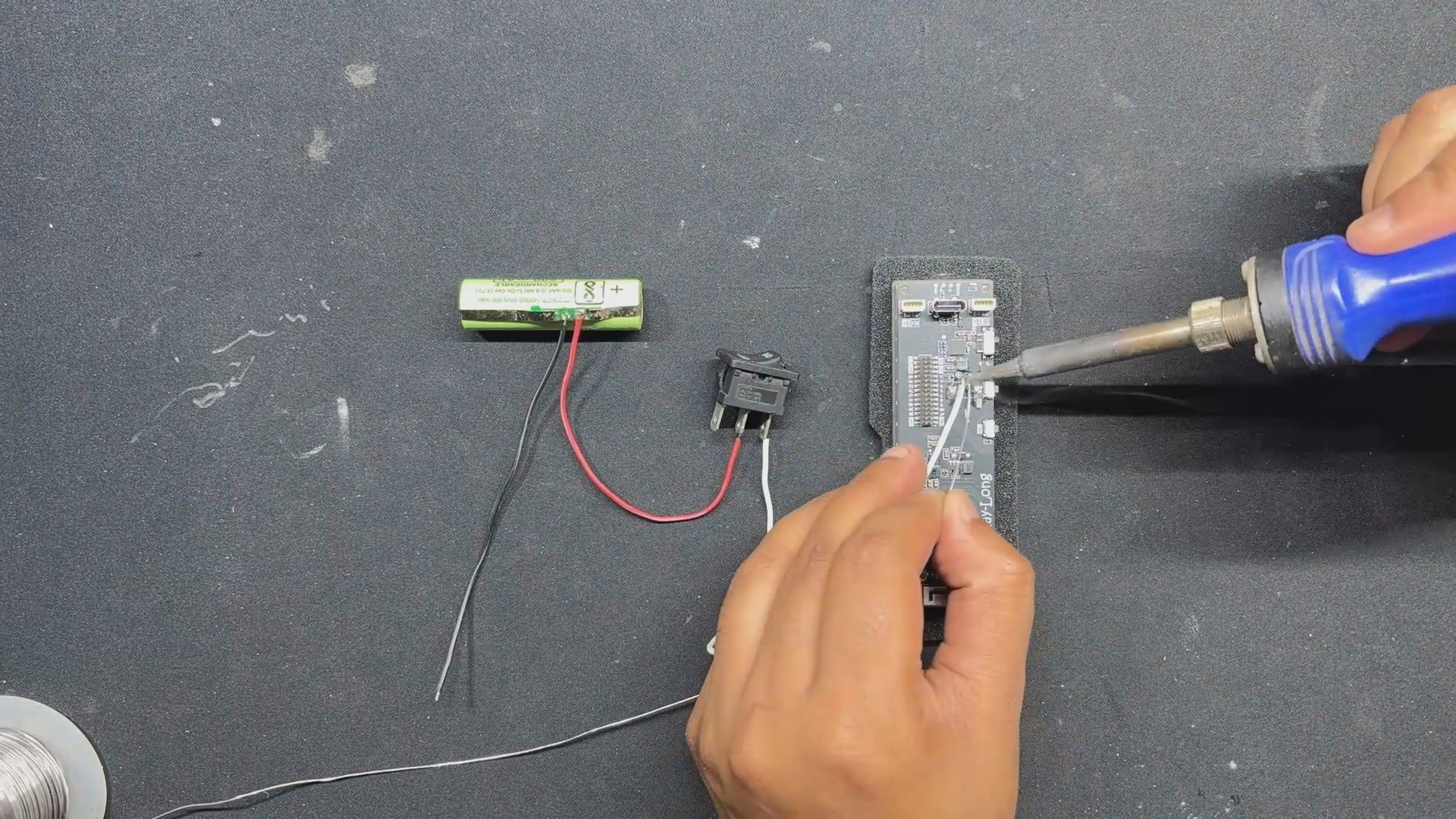
In order to power our TTGO ESP32 Microcontroller, we have even integrated an inbuilt lithium cell.

The code used for this project was adapted from the previous PIP WATCH project, the design was made in Fusion360, and this article explains how to make your own PIP Watch in a few simple steps.

MATERIAL REQUIRED

These are the components used in this build:

  • TTGO T DISPLAY BOARD ESP32 S3 LONG
  • Custom 3D printed Parts
  • M2 Screws
  • 14500 3.7V 600mAh Li-ion Cell
  • Rocker Switch

PIP WATCH VERSION 1

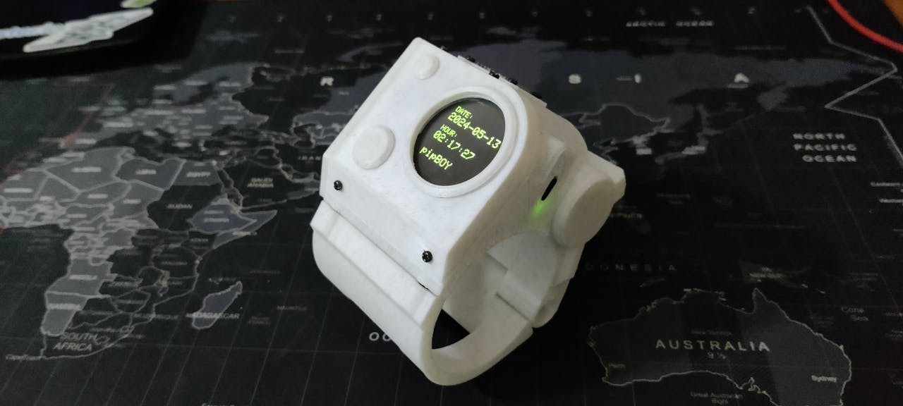
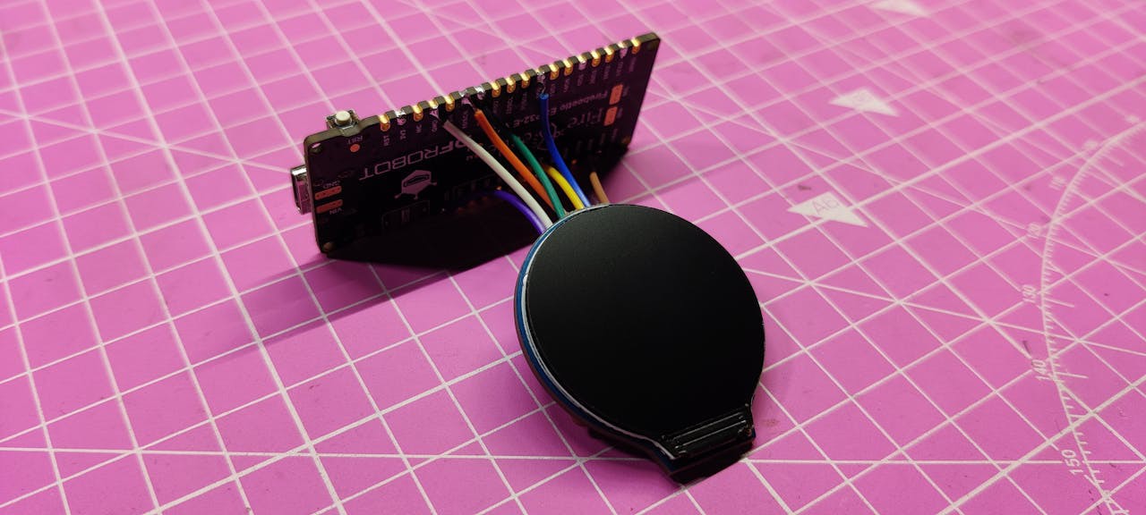
I created a unique watch last year that was based on the Fallout video game series' PIP Boy. This PIP BOY Themed watch, also known as the PIP Watch, was an Internet watch that was driven by a FireBeetle ESP32 board with a round GC9A01 display.

In keeping with the Pipboy theme, PiPWatch receives time from an NTP server and shows the result in green on the round-oled screen.

You can check out more about this project from the below link.

https://www.hackster.io/Arnov_Sharma_makes/pip-watch-project-370245

WHAT IS PIP-BOY?

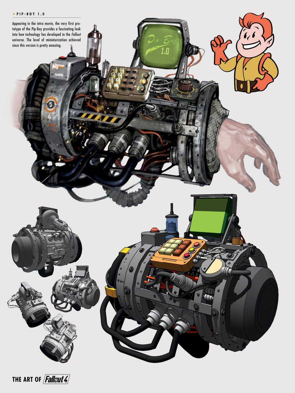
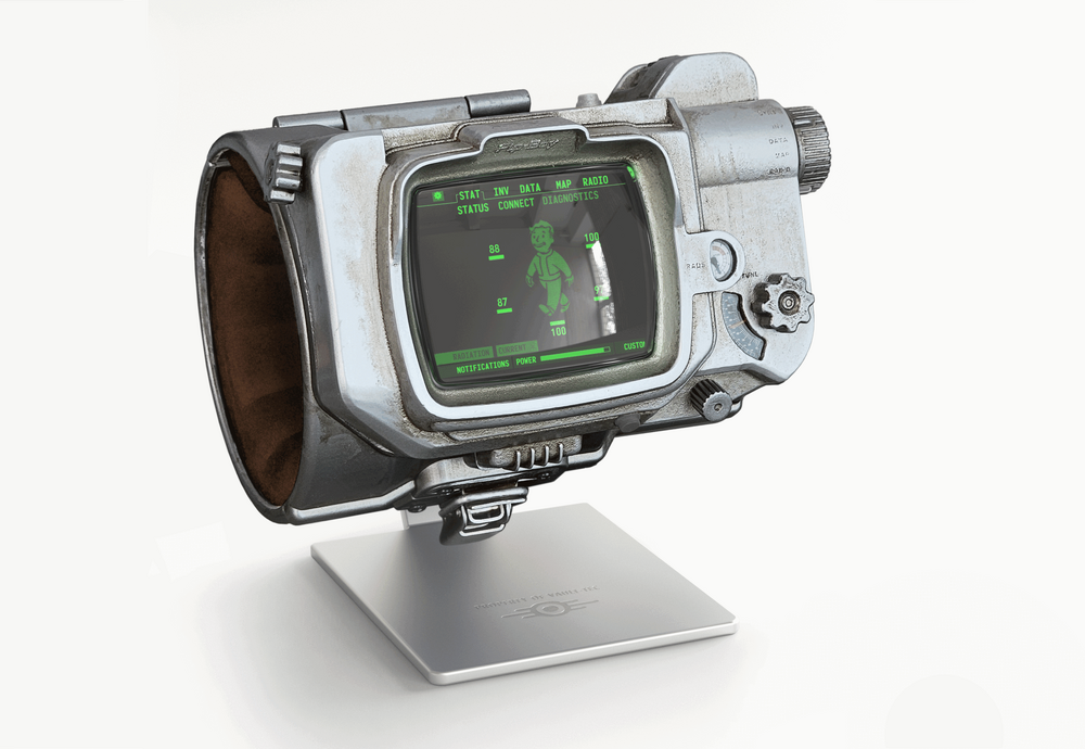
From the Fallout video games, the Pip-Boy is a fantastic small computer that is worn on the wrist. This retro-futuristic green screen on your wrist serves as your all-in-one assistant in the game, allowing you to track tasks, manage your inventory, check your health, and even browse maps.

It comes in a variety of models, each of which represents a specific Fallout timeline event or technological level. Consider the Pip-Boy 2000, a pre-war device manufactured prior to the Great War (2077). It was an early personal assistant with a monochrome display, a very limited interface, and basic stat tracking.

It was more of a lore reference and was hardly ever visible in gameplay.

Then came the Pip-Boy 2000 Mark II, a little better version of the Mark I with more memory and processing, a more durable housing, and a slightly better display. It was still a pre-war device.

The Pip-Boy 3000 from Fallout 3 and New Vegas came next. It included a color screen and tracked statistics like radiation, HP, inventory, map, and quest log, and it even included a flashlight, radio, and holotape reader.

Other versions include the Pip-Boy 1.0/1.1, the Pip-Boy 4000 series, the Pip-Boy 3000 Mark IV, and others.

DESIGN VERSION 2

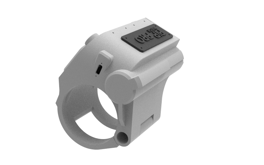
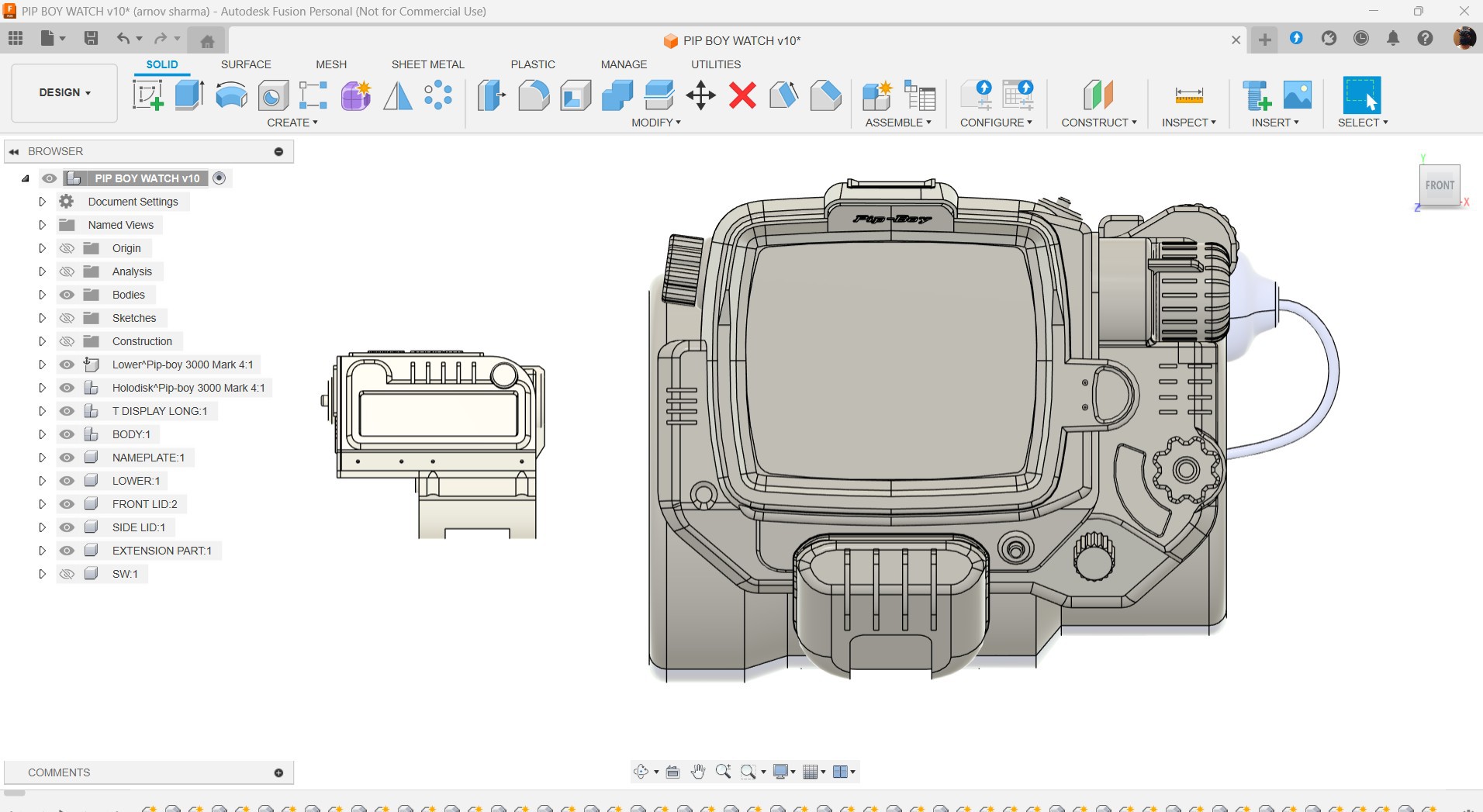
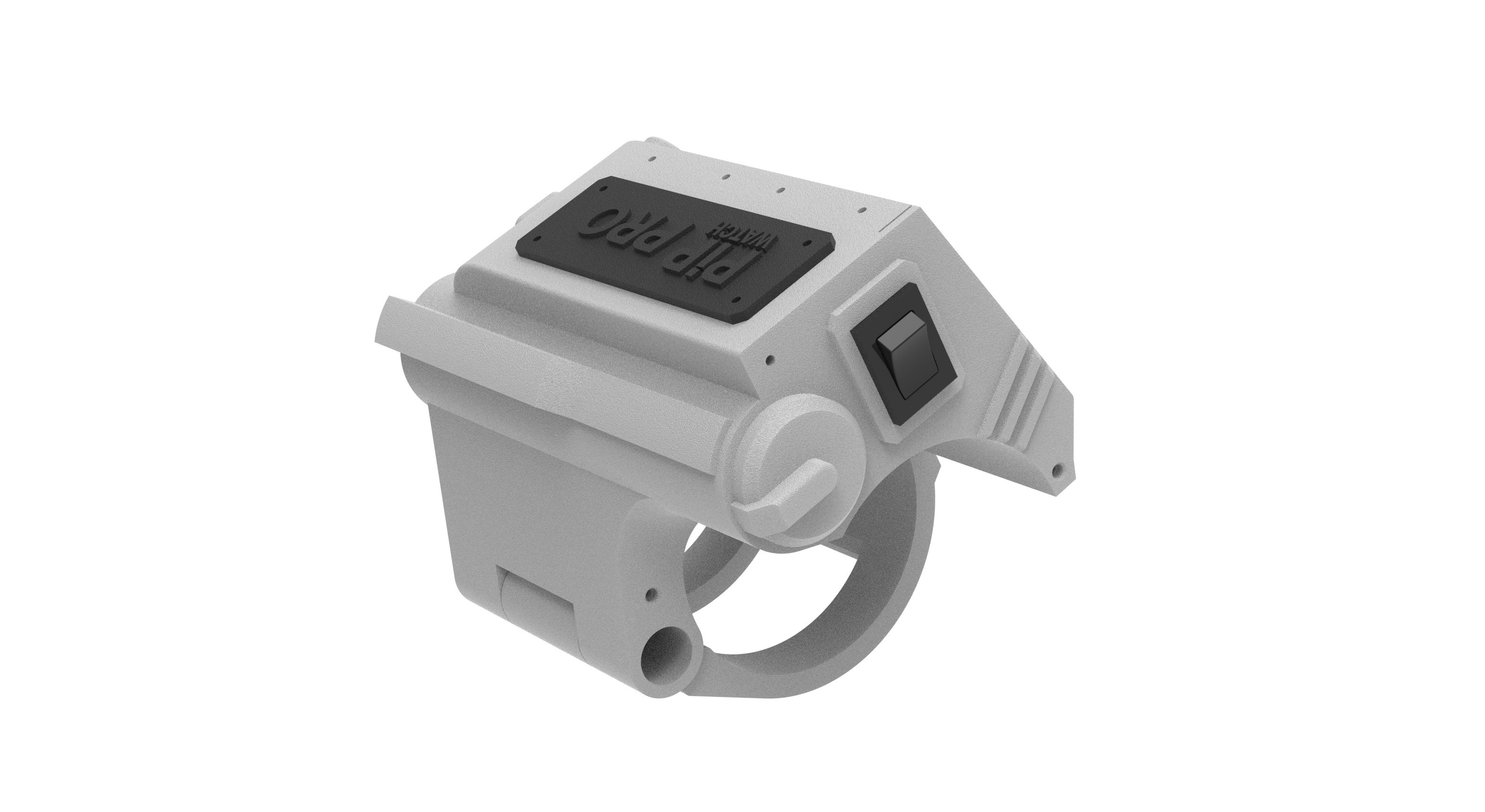
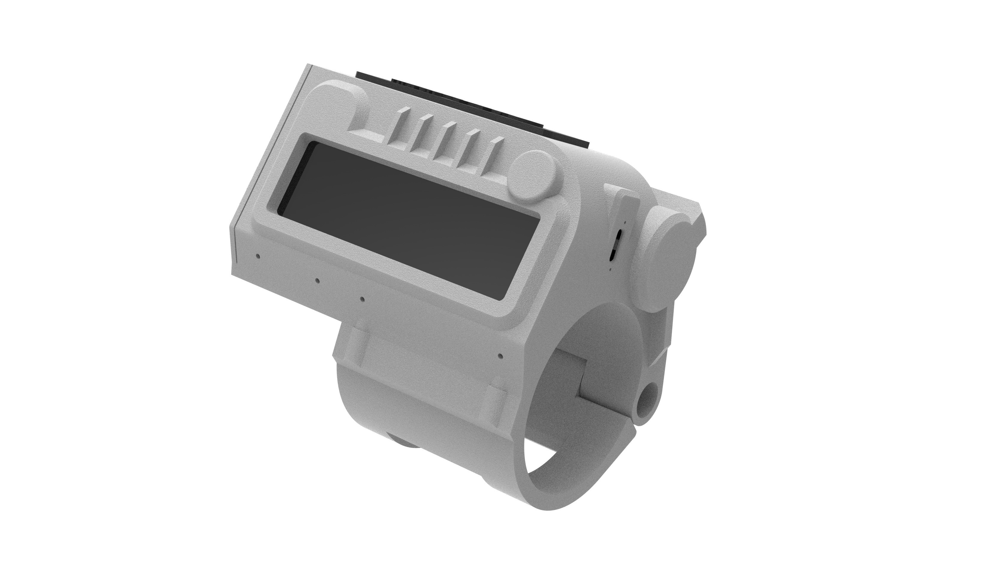
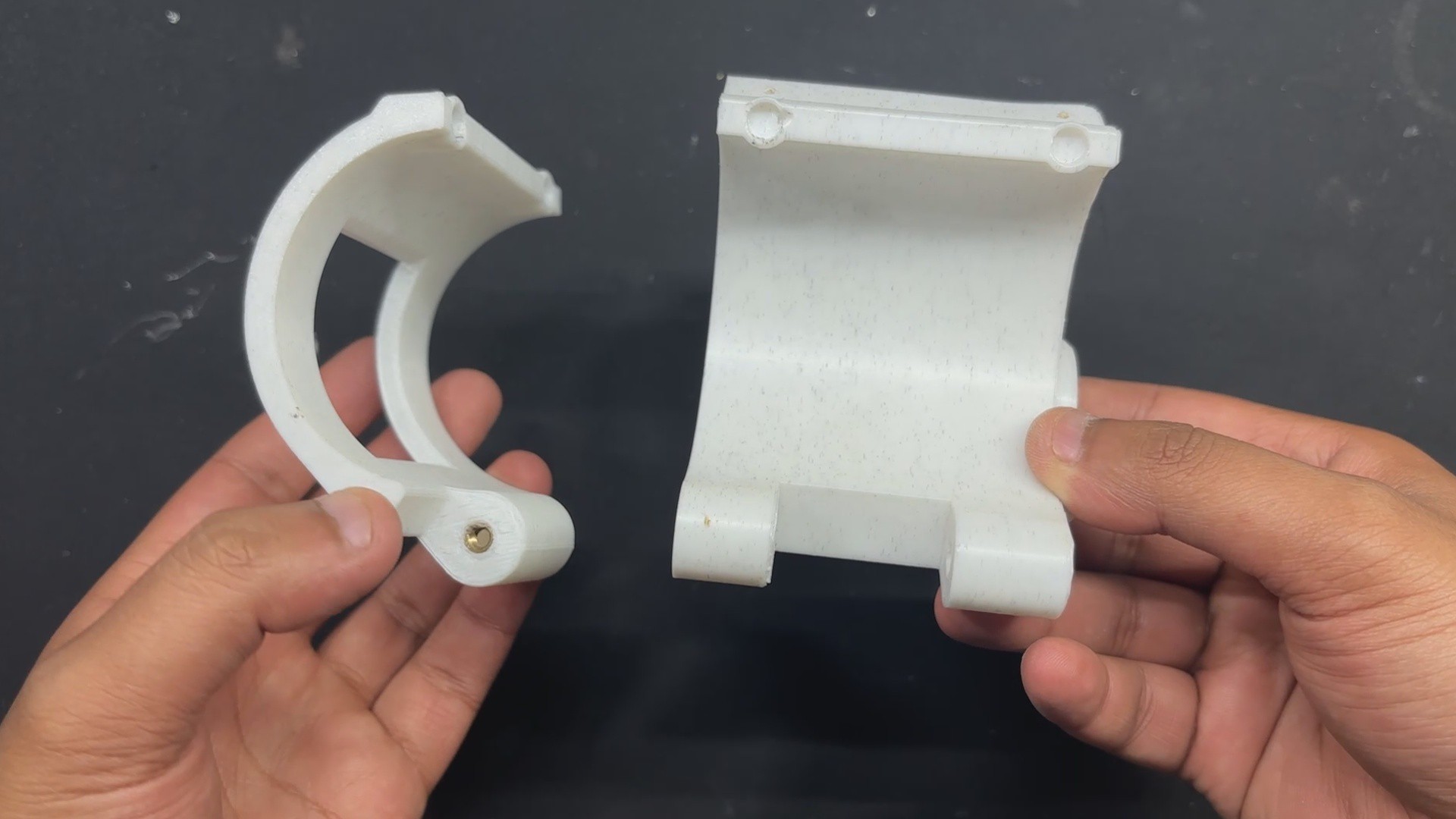
The 3D model was the first step in this project, and our objective was to reuse parts from the previous project.

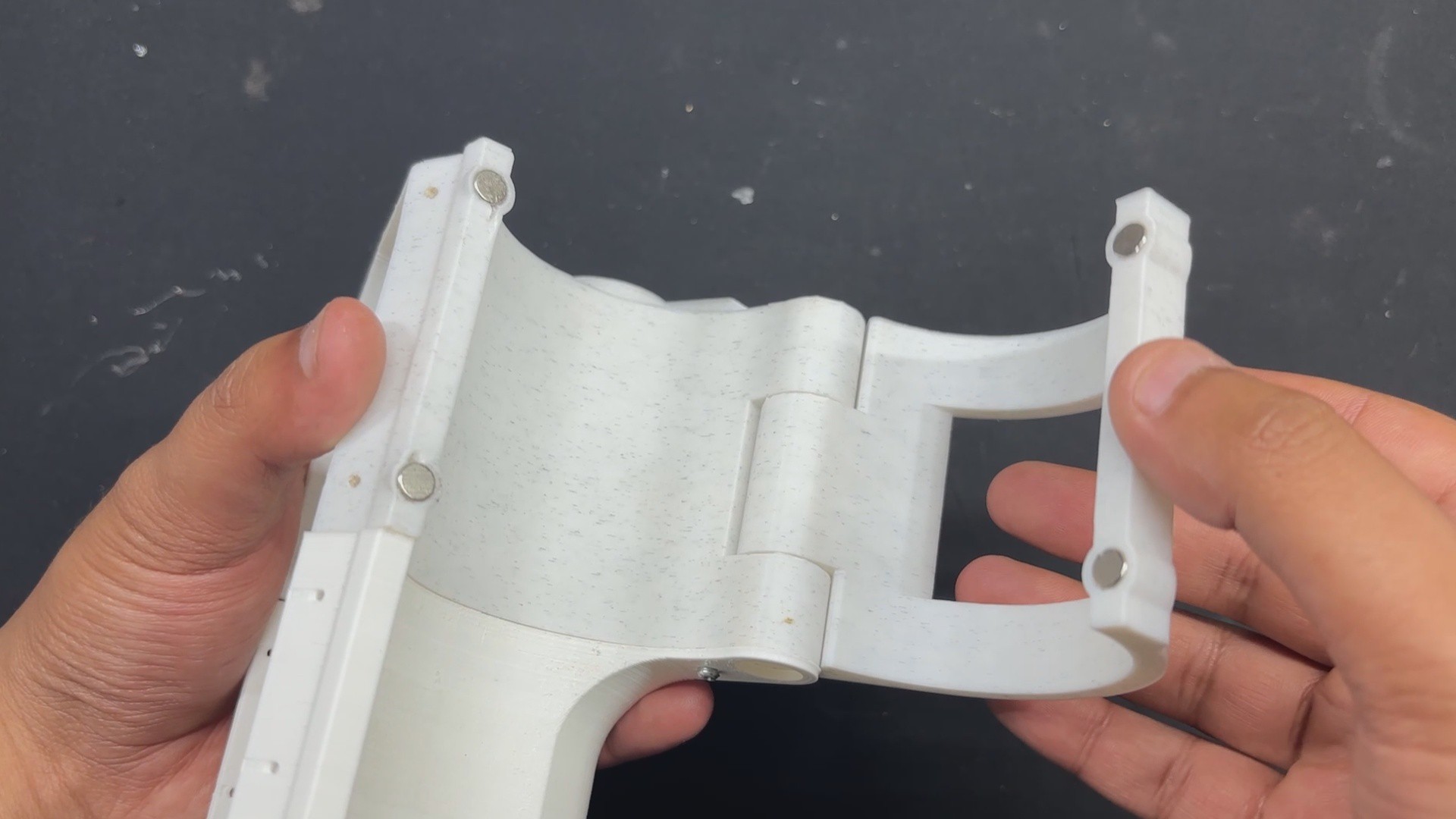
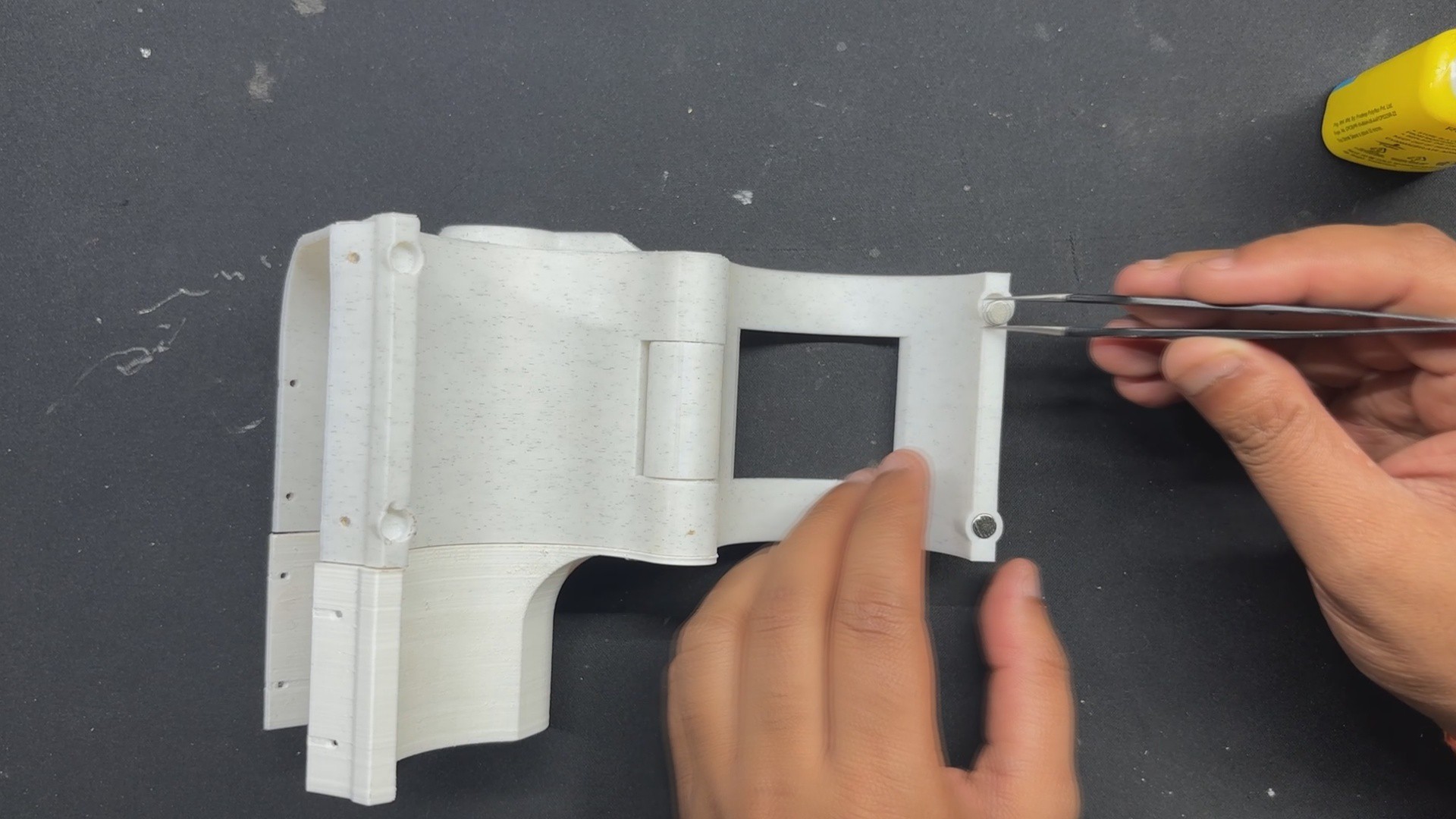
We decide to retain the wrist clamp, which is attached to the main body and pivots on a hinge. In order to keep the hinge clamp part of the watch attached to the body, super magnets are attached to the inside of the clamp and body. The hinge part of the watch is secured in place by these magnets. It can be worn by applying some force to the magnet joints, which will open the clamp and allow the user to put the watch on their wrist.

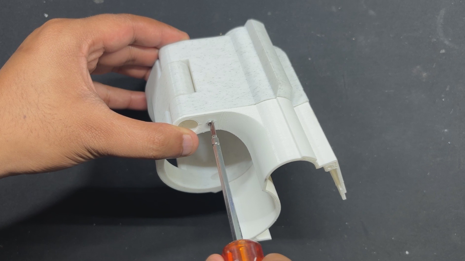
To make it easier to mount the TTGO Display horizontally, we simply modeled a new holder around the main body while maintaining the same structure. Additionally modeled was the new screen holder part that secures the display.

A rocker switch that will be used to turn the setup ON or OFF has been added to the lid part, just like in the previous version.

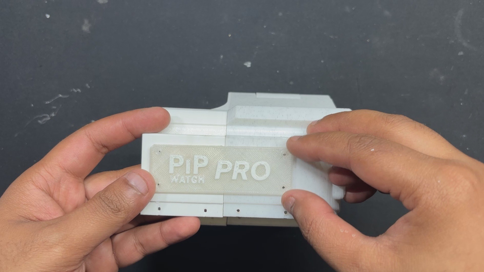
To show that this is a newer version of the PIP WATCH PROJECT SERIES, there is now a nametag that says PIP WATCH PRO.

Once the 3D model was finished, we exported the mesh files and used our ENDER 3...

Read more »

PIP BOY WATCH v10.f3d

fusion - 27.90 MB - 08/19/2025 at 06:15

Download

PIP BOY WATCH v11.step

step - 2.13 MB - 08/19/2025 at 06:14

Download

EXTENSION PART.3mf

3mf - 126.47 kB - 08/19/2025 at 06:14

Download

SIDE LID.3mf

3mf - 68.30 kB - 08/19/2025 at 06:14

Download

FRONT LID.3mf

3mf - 108.41 kB - 08/19/2025 at 06:14

Download

View all 6 files

  • 1
    WIRING PROCESS

    The first step in the entire process is to connect our power source, which is a 14500 3.7V 600mAh Li-ion cell with a PCM.

    The PCM has a DW01 Circuit that gives the cell low and high cut features, which are necessary for charging and discharging the cell correctly without causing a blast.

    • First, we connected the lithium cell's positive and negative terminals to the TTGO Board's positive and negative battery terminals.
    • Next, we attached a switch between the TTGo board and the battery connections. We soldered one end of the positive wire from the battery to the switch's NO terminal, and the switch's NC terminal is linked to the TTGO battery terminal's positive terminal. To break power between the battery and the TTGO board, we installed this switch between them.
  • 2
    MAIN CODE

    This was the code we used in this project, and it’s definitely not the simplest one. First, I want to give a shout-out to the absolute legend nikthefixthanks to the repository he made for this display, we were able to work with it without relying on the code provided by TTGO.

    We mostly followed the code structure from nikthefix’s repo and kept the AXS15231B header and implementation files, which handle communication with the display hardware, including sending pixels, drawing shapes, and initializing the screen.

    #include "AXS15231B.h" #include "pins_config.h" #include <WiFi.h> #include <NTPClient.h> #include <WiFiUdp.h> #define SCREEN_W 640 #define SCREEN_H 180 uint16_t frameBuffer[SCREEN_W * SCREEN_H]; #define RECT_WIDTH (SCREEN_W / 3) #define RECT_HEIGHT SCREEN_H int scale = 6; // bigger numbers #define GREEN 0xE007 #define BLACK 0x0000 const uint8_t font5x7[][5] = { {0x3E,0x51,0x49,0x45,0x3E}, // 0 {0x00,0x42,0x7F,0x40,0x00}, // 1 {0x42,0x61,0x51,0x49,0x46}, // 2 {0x21,0x41,0x45,0x4B,0x31}, // 3 {0x18,0x14,0x12,0x7F,0x10}, // 4 {0x27,0x45,0x45,0x45,0x39}, // 5 {0x3C,0x4A,0x49,0x49,0x30}, // 6 {0x01,0x71,0x09,0x05,0x03}, // 7 {0x36,0x49,0x49,0x49,0x36}, // 8 {0x06,0x49,0x49,0x29,0x1E}, // 9 }; // WiFi credentials const char* ssid = "add your SSID"; const char* password = "add your PASSWORD"; // NTP Client WiFiUDP ntpUDP; NTPClient timeClient(ntpUDP, "pool.ntp.org", 19800); // IST void drawCharScaled(uint16_t *buf, int w, int x, int y, char c, uint16_t color, uint16_t bg, int s){ if(c<'0' || c>'9') return; int idx = c - '0'; for(int col=0; col<5; col++){ uint8_t line = font5x7[idx][col]; for(int row=0; row<7; row++){ uint16_t px_color = (line & (1<<row)) ? color : bg; for(int dx=0; dx<s; dx++){ for(int dy=0; dy<s; dy++){ int px = x + col*s + dx; int py = y + row*s + dy; if(px<w && py<SCREEN_H) buf[py*w + px] = px_color; } } } } } void drawTextScaled(uint16_t *buf, int w, int x, int y, const char* text, uint16_t color, uint16_t bg, int s){ while(*text){ drawCharScaled(buf, w, x, y, *text, color, bg, s); x += (5+1)*s; text++; } } void fillRectBuffer(uint16_t *buf, int w, int x, int y, int rect_w, int rect_h, uint16_t color){ for(int j=0;j<rect_h;j++) for(int i=0;i<rect_w;i++) buf[(y+j)*w + (x+i)] = color; } void drawRectBuffer(uint16_t *buf, int w, int x, int y, int rect_w, int rect_h, uint16_t color){ for(int i=0;i<rect_w;i++){ buf[y*w + x + i] = color; buf[(y+rect_h-1)*w + x + i] = color; } for(int j=0;j<rect_h;j++){ buf[(y+j)*w + x] = color; buf[(y+j)*w + x + rect_w-1] = color; } } void setup() { pinMode(TFT_BL, OUTPUT); digitalWrite(TFT_BL, HIGH); axs15231_init(); Serial.begin(115200); WiFi.begin(ssid, password); Serial.print("Connecting to WiFi"); while(WiFi.status() != WL_CONNECTED){ delay(500); Serial.print("."); } Serial.println("\nWiFi connected"); timeClient.begin(); // Draw static rectangles once fillRectBuffer(frameBuffer, SCREEN_W, 0, 0, SCREEN_W, SCREEN_H, BLACK); drawRectBuffer(frameBuffer, SCREEN_W, 0, 0, RECT_WIDTH, RECT_HEIGHT, GREEN); drawRectBuffer(frameBuffer, SCREEN_W, RECT_WIDTH, 0, RECT_WIDTH, RECT_HEIGHT, GREEN); drawRectBuffer(frameBuffer, SCREEN_W, RECT_WIDTH*2, 0, RECT_WIDTH, RECT_HEIGHT, GREEN); lcd_PushColors_rotated_90(0,0,SCREEN_W,SCREEN_H, frameBuffer); } int prevHours=-1, prevMinutes=-1, prevSeconds=-1; void loop(){ if(timeClient.update()){ int hours = timeClient.getHours(); int minutes = timeClient.getMinutes(); int seconds = timeClient.getSeconds(); char buf[3]; int y_center = (SCREEN_H - 7*scale) / 2; // Only update digits that changed if(hours != prevHours){ sprintf(buf,"%02d", hours); fillRectBuffer(frameBuffer, SCREEN_W, 0, y_center, RECT_WIDTH, 7*scale, BLACK); drawTextScaled(frameBuffer, SCREEN_W, RECT_WIDTH/2 - scale*6, y_center, buf, GREEN, BLACK, scale); prevHours = hours; } if(minutes != prevMinutes){ sprintf(buf,"%02d", minutes); fillRectBuffer(frameBuffer, SCREEN_W, RECT_WIDTH, y_center, RECT_WIDTH, 7*scale, BLACK); drawTextScaled(frameBuffer, SCREEN_W, RECT_WIDTH + RECT_WIDTH/2 - scale*6, y_center, buf, GREEN, BLACK, scale); prevMinutes = minutes; } if(seconds != prevSeconds){ sprintf(buf,"%02d", seconds); fillRectBuffer(frameBuffer, SCREEN_W, RECT_WIDTH*2, y_center, RECT_WIDTH, 7*scale, BLACK); drawTextScaled(frameBuffer, SCREEN_W, RECT_WIDTH*2 + RECT_WIDTH/2 - scale*6, y_center, buf, GREEN, BLACK, scale); prevSeconds = seconds; } lcd_PushColors_rotated_90(0,0,SCREEN_W,SCREEN_H, frameBuffer); } }

    The code begins by adding Libraries and the custom header files that are required for Wi-Fi, NTP Server, pin definitions and Display initialization.

    The AXS15231B library handles the AXS15231 display, including initialization and drawing functions.

    pins_config Contains your pin definitions for the display, backlight, and other hardware connections.

    Wifi.h is the ESP32 Wi-Fi library for connecting to a wireless network.

    NTPClient is used for getting the current time from an NTP server over the internet.

    the WiFiUdp is the UDP protocol library required by NTPClient to fetch time.

    Display and Graphics Setup

     #define SCREEN_W 640#define SCREEN_H 180uint16_t frameBuffer[SCREEN_W * SCREEN_H];#define RECT_WIDTH (SCREEN_W / 3)#define RECT_HEIGHT SCREEN_Hint scale = 6; // scaling factor for bigger digits#define GREEN 0xE007#define BLACK 0x0000

    This section specifies the height and width of the screen, the rectangle width, the pixel buffer, and the digit scaling. Frame Pixel colors are saved in a buffer before being sent to the LCD. The RGB565 16-bit format is used to define colors.

    Font Definition

     const uint8_t font5x7[][5] = { {0x3E,0x51,0x49,0x45,0x3E}, // 0 {0x00,0x42,0x7F,0x40,0x00}, // 1 {0x42,0x61,0x51,0x49,0x46}, // 2 {0x21,0x41,0x45,0x4B,0x31}, // 3 {0x18,0x14,0x12,0x7F,0x10}, // 4 {0x27,0x45,0x45,0x45,0x39}, // 5 {0x3C,0x4A,0x49,0x49,0x30}, // 6 {0x01,0x71,0x09,0x05,0x03}, // 7 {0x36,0x49,0x49,0x49,0x36}, // 8 {0x06,0x49,0x49,0x29,0x1E}, // 9};

    The numbers 0–9 are represented by this 5x7 pixel representation, which was used to manually draw the digits on the framebuffer.

    WiFi & NTP Setup

     const char* ssid = "ADD YOUR SSID";const char* password = "ADD YOUR PASS";WiFiUDP ntpUDP;NTPClient timeClient(ntpUDP, "pool.ntp.org", 19800); // IST (UTC+5:30)

    This part connects to WiFi and sets up an NTP client to fetch time in Indian Standard Time.

    Drawing Functions

     void drawCharScaled(...) {...}void drawTextScaled(...) {...}void fillRectBuffer(...) {...}void drawRectBuffer(...) {...}

    A single character scaled by scale is drawn using the drawCharScaled function.

    A string of characters is drawn using the drawTextScaled method.

    A rectangular region in the framebuffer is filled using the fillRectBuffer function.

    A rectangular border is drawn using the drawRectBuffer function.

    Setup Function

     void setup() { pinMode(TFT_BL, OUTPUT); digitalWrite(TFT_BL, HIGH); // Turn on backlight axs15231_init(); // Initialize LCD Serial.begin(115200); WiFi.begin(ssid, password); // Connect to WiFi while(WiFi.status() != WL_CONNECTED){ delay(500); } timeClient.begin(); // Start NTP client fillRectBuffer(frameBuffer, SCREEN_W, 0, 0, SCREEN_W, SCREEN_H, BLACK); drawRectBuffer(...) // Draw 3 green rectangle borders for HH:MM:SS lcd_PushColors_rotated_90(0,0,SCREEN_W,SCREEN_H, frameBuffer); // Send framebuffer to LCD}

    This section sets up the NTP, WiFi, and display. After that, it sends the first framebuffer to the screen and draws static green rectangular boundaries for the hours, minutes, and seconds.

    Loop Function

     void loop(){ if(timeClient.update()){ // Update time from NTP int hours = timeClient.getHours(); int minutes = timeClient.getMinutes(); int seconds = timeClient.getSeconds(); ... // Only redraw digits if they have changed lcd_PushColors_rotated_90(0,0,SCREEN_W,SCREEN_H, frameBuffer); // Refresh display }}

    This part sends the new framebuffer to the display after continuously updating the time via NTP and verifying that each digit (hours, minutes, and seconds) has changed. It then only redraws the altered digits to minimize flicker.

    The main code file must be saved in a folder and the included header files, such as AXS15231B.h, pins_config.h, and AXS15231B.cpp, must be added to set up the sketch.

  • 3
    BASE FRAME ASSEMBLY PROCESS
    • We now start the project's Body build, which starts with setting up the project's Base. We fasten the main body with the lower clamp part using M2.5 bolts.
    • The extension part is then positioned over one side of the main body, its mounting hole is aligned with the main body, and an M2 screw is used to fasten them together.
    • The nameplate, which essentially holds the main body and extension section together with four screws positioned in corners, is installed in place once the extension part has been placed.
    • Next, we add tiny magnets with a diameter of 5 mm to the main body and clamp part. Our first step is to apply a drop of super glue to the magnet's clamp mounting place. This will ensure that the magnet remains in place permanently.
    • Similar to this, we add magnets to the main body by following the same process, but we make sure to face them in the correct direction since this section employs two magnets to create a magnetic lock, and magnetism is crucial in this situation; utilizing the same poles on the same side will break the entire system.

View all 9 instructions

Enjoy this project?

Share

Discussions

Does this project spark your interest?

Become a member to follow this project and never miss any updates