 CrazyChip
Main features:
- Selectable frequencies of spectrum to display (512 possible frequencies)
- Configurable via serial connection (TTL level)
- Any character LCD will fit - from 16x2 to 80x4
Already have an account? Log in.
To make the experience fit your profile, pick a username and tell us what interests you.
Main features:
You can see the progress in the quarterfinal video:
Works:
Missing:
A check-list of quarterfinal:
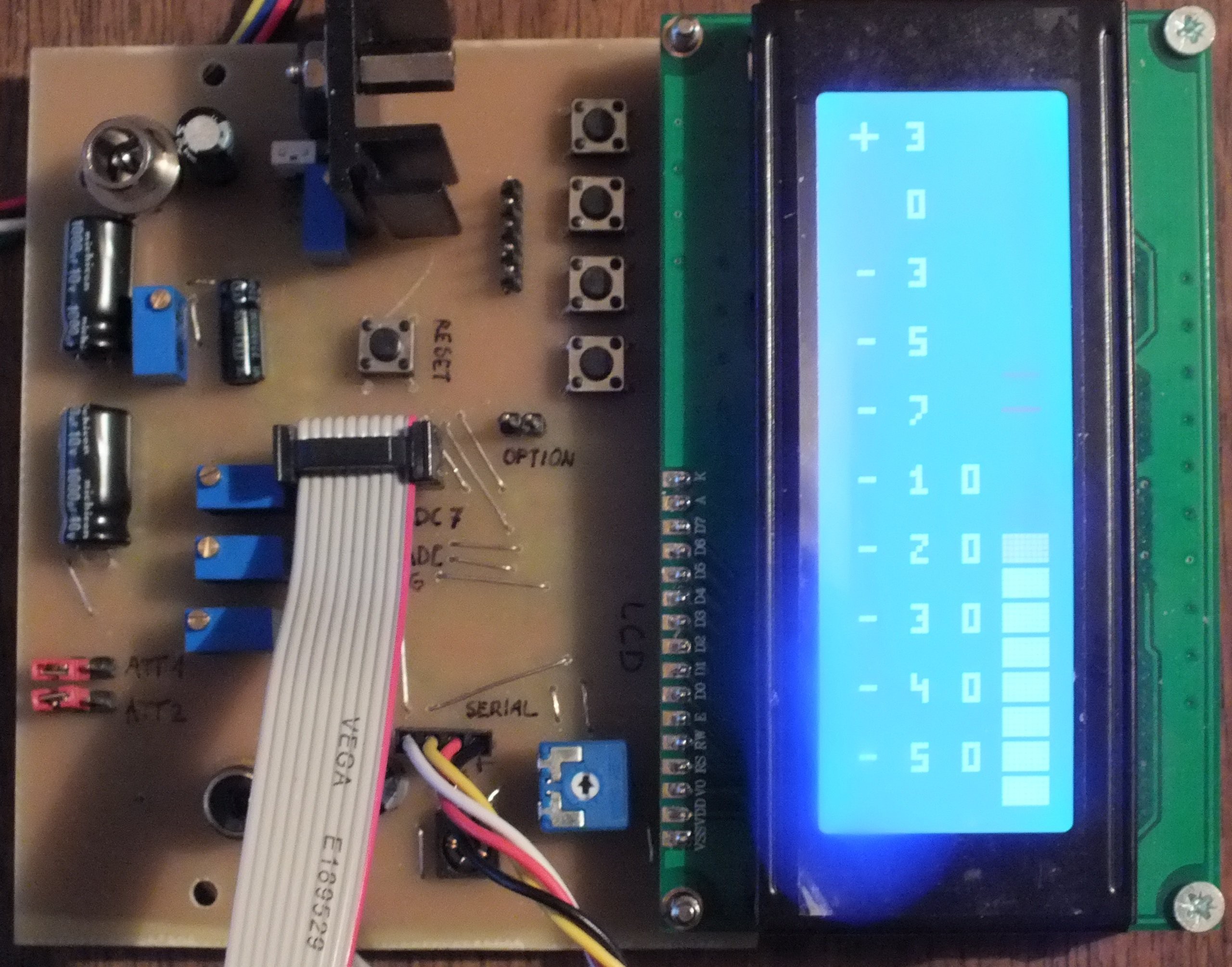
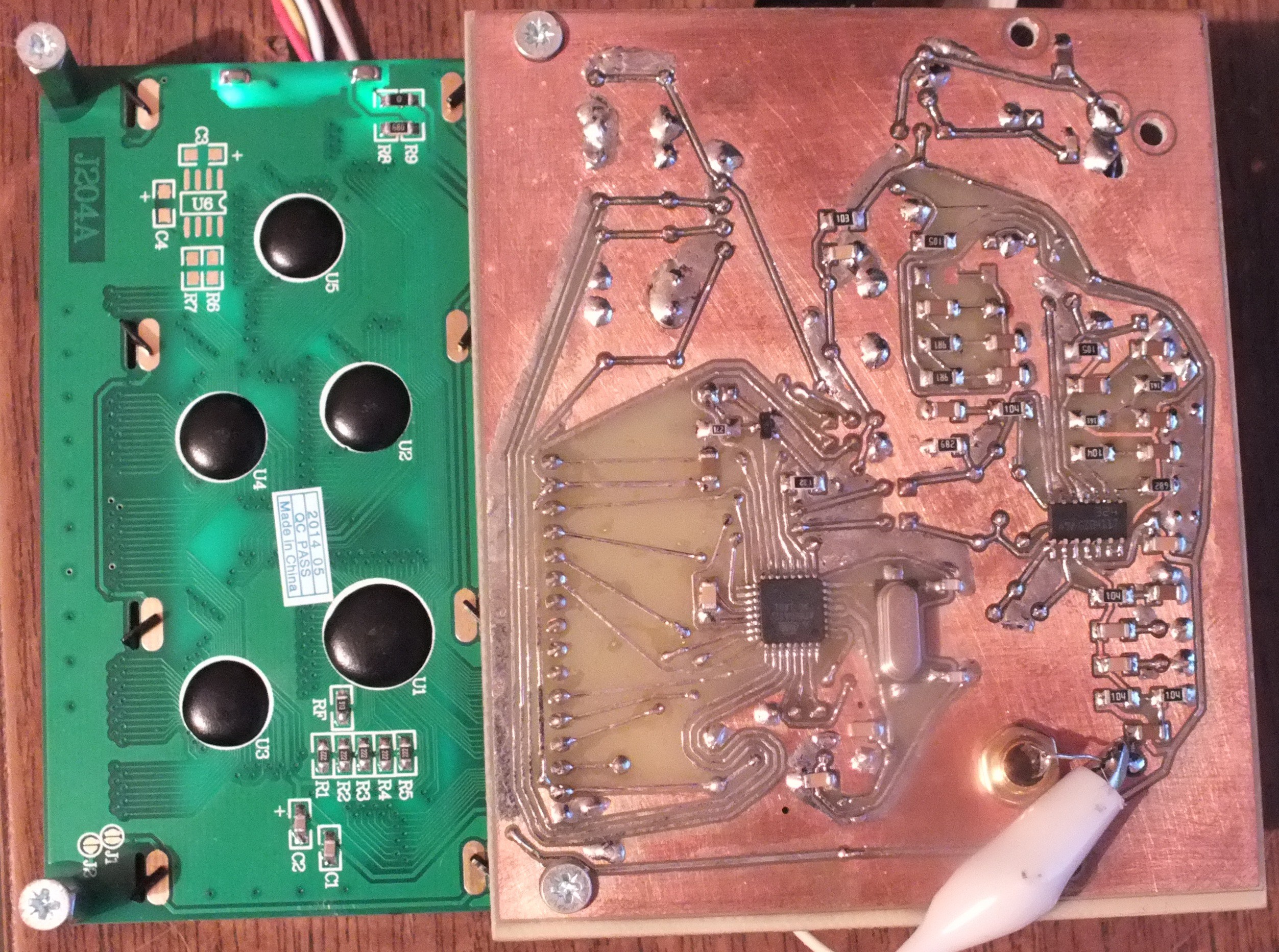
I soldered all the parts. The layout of the board is terrible but it works.
Some notes:
So, looks like a list of several small improvements for the next version of the PCB :)
Block diagram added to show possible connections of the external devices

Kicad files committed to GitHub
https://github.com/CrazyChip/spectrum
Schematic in PDF also included:
https://github.com/CrazyChip/spectrum/blob/master/schematic/sa.pdf
One-sided PCB is traced with Toporouter for prototype only.
A smaller two-sided PCB is planned after testing the prototype.
Youtube video shows a very early prototype implemented on Arduino using 20x4 character LCD.
Test signal is generated with Matlab (background music is not used as a signal).
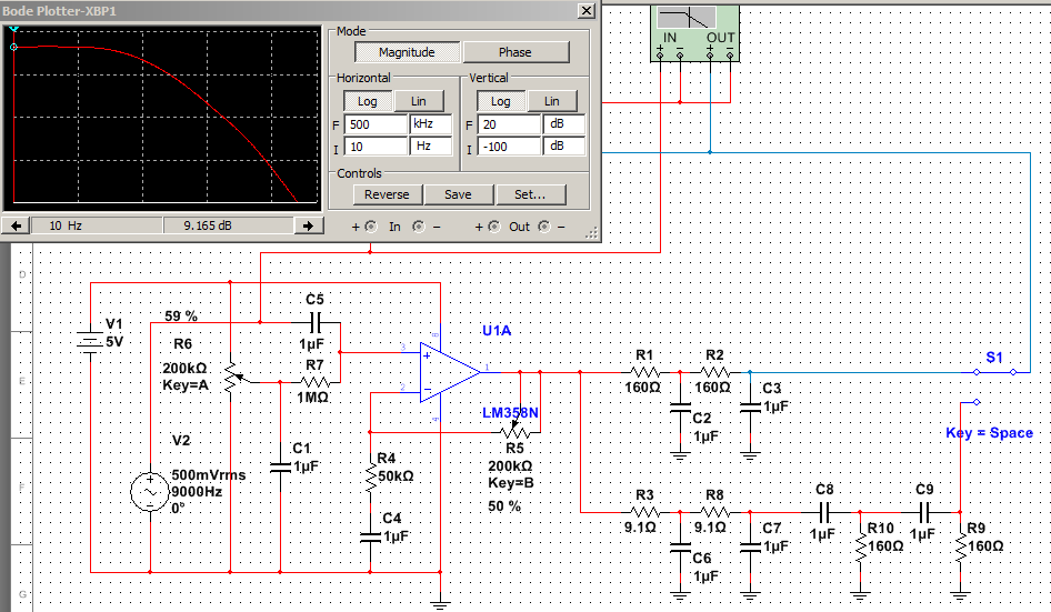
Design stage: two low-pass filters - 1kHz and 16kHz - simulated on Multisim.
[this comment has been deleted]
http://ecx.images-amazon.com/images/I/41gGJ8BjOfL._SY300_.jpg