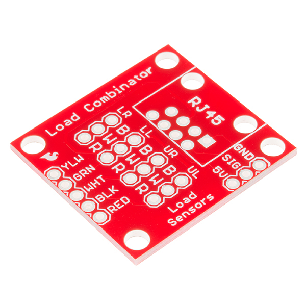
If you open up an electronic bathroom scale you’ll find a large rats nest of wires. The Load Sensor Combinator was created to combine the 12 wires found in a bathroom scale into the standard 4-wires that wheatstone bridge configuration.
This board also works with four of our individual load sensors. If you aren’t mechanically inclined we recommend purchasing an off-the-shelf bathroom scale and hacking the combinator into it rather than trying to design a base to properly mount four load sensors.
This board works great with our Load Cell Amplifier breakout board. The fine pins on the edge of the combinator line directly up to the five pins on the amplifier.
If your amplifier and supporting electronics are more than a few inches away from the scale an RJ45 footprint is provided. The 4 wheatstone pins (E+/E-/S+/S-) as well as the shield pin are connected to twisted pairs within a standard cheap ethernet cable. This allows the amplifier board to be placed many feet away from the scale itself.
The combinator board also includes a footprint for the DS18B20 one wire temperature sensor. This allows the user to gather the temperature of the scale in case there is a large variance between the scale and the amplifier. These three pins are exposed to the RJ45 connection as well allowing remote temperature readings to be gathered over one twisted pair ethernet cable.
If you are using the RJ45 connection please note the following wire colors:
- Combinator Pin -> Ethernet cable wire color
- E+ -> Brown
- E- -> Brown white
- NC -> Green
- A+ -> Blue white
- A- -> Blue
- 5V -> Green white
- TEMP_DAT -> Orange
- GND -> Orange white
The NC pin is intentionally left not connected. For especially long cables the signals should be shielded against EMI. This is done by using the less common shielded twisted pair ethernet cable. The metal shield of the cable creates a telescoping shield by connecting it to ground on the amplifier circuit, not on GND or any other pin on the combinator board.
This code is public domain but you buy me a beer if you use this and we meet someday (Beerware license).